EP3662948B1 - A dispensing device - Google Patents
A dispensing device Download PDFInfo
- Publication number
- EP3662948B1 EP3662948B1 EP19196452.7A EP19196452A EP3662948B1 EP 3662948 B1 EP3662948 B1 EP 3662948B1 EP 19196452 A EP19196452 A EP 19196452A EP 3662948 B1 EP3662948 B1 EP 3662948B1
- Authority
- EP
- European Patent Office
- Prior art keywords
- nozzle
- cap member
- housing
- cap
- extension
- Prior art date
- Legal status (The legal status is an assumption and is not a legal conclusion. Google has not performed a legal analysis and makes no representation as to the accuracy of the status listed.)
- Active
Links
- 239000003814 drug Substances 0.000 claims description 20
- 230000033001 locomotion Effects 0.000 claims description 16
- 239000000126 substance Substances 0.000 claims description 7
- 229940071648 metered dose inhaler Drugs 0.000 claims description 2
- 230000001419 dependent effect Effects 0.000 claims 7
- 239000000428 dust Substances 0.000 description 75
- 239000000203 mixture Substances 0.000 description 22
- 238000009472 formulation Methods 0.000 description 21
- 239000000443 aerosol Substances 0.000 description 9
- 230000000994 depressogenic effect Effects 0.000 description 9
- 239000000463 material Substances 0.000 description 7
- 230000000295 complement effect Effects 0.000 description 5
- 238000010304 firing Methods 0.000 description 5
- 238000012986 modification Methods 0.000 description 4
- 230000004048 modification Effects 0.000 description 4
- 239000004033 plastic Substances 0.000 description 4
- 229920003023 plastic Polymers 0.000 description 4
- 239000003380 propellant Substances 0.000 description 4
- 239000004743 Polypropylene Substances 0.000 description 3
- 229940112141 dry powder inhaler Drugs 0.000 description 3
- 239000012530 fluid Substances 0.000 description 3
- 229920001155 polypropylene Polymers 0.000 description 3
- 239000000843 powder Substances 0.000 description 3
- 238000005728 strengthening Methods 0.000 description 3
- 208000006673 asthma Diseases 0.000 description 2
- 238000004891 communication Methods 0.000 description 2
- 238000010276 construction Methods 0.000 description 2
- 230000003434 inspiratory effect Effects 0.000 description 2
- 238000004519 manufacturing process Methods 0.000 description 2
- -1 polypropylene Polymers 0.000 description 2
- 239000000047 product Substances 0.000 description 2
- 238000013102 re-test Methods 0.000 description 2
- 230000001105 regulatory effect Effects 0.000 description 2
- 239000007921 spray Substances 0.000 description 2
- 230000000007 visual effect Effects 0.000 description 2
- YFMFNYKEUDLDTL-UHFFFAOYSA-N 1,1,1,2,3,3,3-heptafluoropropane Chemical compound FC(F)(F)C(F)C(F)(F)F YFMFNYKEUDLDTL-UHFFFAOYSA-N 0.000 description 1
- LVGUZGTVOIAKKC-UHFFFAOYSA-N 1,1,1,2-tetrafluoroethane Chemical compound FCC(F)(F)F LVGUZGTVOIAKKC-UHFFFAOYSA-N 0.000 description 1
- 208000006545 Chronic Obstructive Pulmonary Disease Diseases 0.000 description 1
- 230000001154 acute effect Effects 0.000 description 1
- 239000002671 adjuvant Substances 0.000 description 1
- 239000004411 aluminium Substances 0.000 description 1
- 229910052782 aluminium Inorganic materials 0.000 description 1
- XAGFODPZIPBFFR-UHFFFAOYSA-N aluminium Chemical compound [Al] XAGFODPZIPBFFR-UHFFFAOYSA-N 0.000 description 1
- 230000002917 arthritic effect Effects 0.000 description 1
- 230000000712 assembly Effects 0.000 description 1
- 238000000429 assembly Methods 0.000 description 1
- 230000000903 blocking effect Effects 0.000 description 1
- 230000001684 chronic effect Effects 0.000 description 1
- 230000001934 delay Effects 0.000 description 1
- 230000008021 deposition Effects 0.000 description 1
- 238000013461 design Methods 0.000 description 1
- 238000011161 development Methods 0.000 description 1
- 230000018109 developmental process Effects 0.000 description 1
- 230000000694 effects Effects 0.000 description 1
- 239000010419 fine particle Substances 0.000 description 1
- 238000001746 injection moulding Methods 0.000 description 1
- 238000009434 installation Methods 0.000 description 1
- 230000007794 irritation Effects 0.000 description 1
- 239000007788 liquid Substances 0.000 description 1
- 235000011475 lollipops Nutrition 0.000 description 1
- 210000004072 lung Anatomy 0.000 description 1
- 230000014759 maintenance of location Effects 0.000 description 1
- 229910052751 metal Inorganic materials 0.000 description 1
- 239000002184 metal Substances 0.000 description 1
- 238000000034 method Methods 0.000 description 1
- 238000000465 moulding Methods 0.000 description 1
- 238000004806 packaging method and process Methods 0.000 description 1
- 239000000546 pharmaceutical excipient Substances 0.000 description 1
- 238000003825 pressing Methods 0.000 description 1
- 238000011321 prophylaxis Methods 0.000 description 1
- 230000003014 reinforcing effect Effects 0.000 description 1
- 230000000241 respiratory effect Effects 0.000 description 1
- 210000002345 respiratory system Anatomy 0.000 description 1
- 208000023504 respiratory system disease Diseases 0.000 description 1
- 206010039083 rhinitis Diseases 0.000 description 1
- 238000000926 separation method Methods 0.000 description 1
- 239000000243 solution Substances 0.000 description 1
- 239000013589 supplement Substances 0.000 description 1
- 239000000725 suspension Substances 0.000 description 1
- 238000010408 sweeping Methods 0.000 description 1
- 208000024891 symptom Diseases 0.000 description 1
- 230000001225 therapeutic effect Effects 0.000 description 1
- 238000011282 treatment Methods 0.000 description 1
Images


Classifications
-
- A—HUMAN NECESSITIES
- A61—MEDICAL OR VETERINARY SCIENCE; HYGIENE
- A61M—DEVICES FOR INTRODUCING MEDIA INTO, OR ONTO, THE BODY; DEVICES FOR TRANSDUCING BODY MEDIA OR FOR TAKING MEDIA FROM THE BODY; DEVICES FOR PRODUCING OR ENDING SLEEP OR STUPOR
- A61M15/00—Inhalators
-
- A—HUMAN NECESSITIES
- A61—MEDICAL OR VETERINARY SCIENCE; HYGIENE
- A61M—DEVICES FOR INTRODUCING MEDIA INTO, OR ONTO, THE BODY; DEVICES FOR TRANSDUCING BODY MEDIA OR FOR TAKING MEDIA FROM THE BODY; DEVICES FOR PRODUCING OR ENDING SLEEP OR STUPOR
- A61M11/00—Sprayers or atomisers specially adapted for therapeutic purposes
- A61M11/04—Sprayers or atomisers specially adapted for therapeutic purposes operated by the vapour pressure of the liquid to be sprayed or atomised
-
- A—HUMAN NECESSITIES
- A61—MEDICAL OR VETERINARY SCIENCE; HYGIENE
- A61M—DEVICES FOR INTRODUCING MEDIA INTO, OR ONTO, THE BODY; DEVICES FOR TRANSDUCING BODY MEDIA OR FOR TAKING MEDIA FROM THE BODY; DEVICES FOR PRODUCING OR ENDING SLEEP OR STUPOR
- A61M15/00—Inhalators
- A61M15/0001—Details of inhalators; Constructional features thereof
- A61M15/0021—Mouthpieces therefor
- A61M15/0023—Mouthpieces therefor retractable
-
- A—HUMAN NECESSITIES
- A61—MEDICAL OR VETERINARY SCIENCE; HYGIENE
- A61M—DEVICES FOR INTRODUCING MEDIA INTO, OR ONTO, THE BODY; DEVICES FOR TRANSDUCING BODY MEDIA OR FOR TAKING MEDIA FROM THE BODY; DEVICES FOR PRODUCING OR ENDING SLEEP OR STUPOR
- A61M15/00—Inhalators
- A61M15/0001—Details of inhalators; Constructional features thereof
- A61M15/0021—Mouthpieces therefor
- A61M15/0025—Mouthpieces therefor with caps
-
- A—HUMAN NECESSITIES
- A61—MEDICAL OR VETERINARY SCIENCE; HYGIENE
- A61M—DEVICES FOR INTRODUCING MEDIA INTO, OR ONTO, THE BODY; DEVICES FOR TRANSDUCING BODY MEDIA OR FOR TAKING MEDIA FROM THE BODY; DEVICES FOR PRODUCING OR ENDING SLEEP OR STUPOR
- A61M15/00—Inhalators
- A61M15/0065—Inhalators with dosage or measuring devices
- A61M15/0068—Indicating or counting the number of dispensed doses or of remaining doses
- A61M15/007—Mechanical counters
- A61M15/0071—Mechanical counters having a display or indicator
- A61M15/0076—Mechanical counters having a display or indicator on a drum
-
- A—HUMAN NECESSITIES
- A61—MEDICAL OR VETERINARY SCIENCE; HYGIENE
- A61M—DEVICES FOR INTRODUCING MEDIA INTO, OR ONTO, THE BODY; DEVICES FOR TRANSDUCING BODY MEDIA OR FOR TAKING MEDIA FROM THE BODY; DEVICES FOR PRODUCING OR ENDING SLEEP OR STUPOR
- A61M15/00—Inhalators
- A61M15/0065—Inhalators with dosage or measuring devices
- A61M15/0068—Indicating or counting the number of dispensed doses or of remaining doses
- A61M15/0081—Locking means
-
- A—HUMAN NECESSITIES
- A61—MEDICAL OR VETERINARY SCIENCE; HYGIENE
- A61M—DEVICES FOR INTRODUCING MEDIA INTO, OR ONTO, THE BODY; DEVICES FOR TRANSDUCING BODY MEDIA OR FOR TAKING MEDIA FROM THE BODY; DEVICES FOR PRODUCING OR ENDING SLEEP OR STUPOR
- A61M15/00—Inhalators
- A61M15/009—Inhalators using medicine packages with incorporated spraying means, e.g. aerosol cans
-
- A—HUMAN NECESSITIES
- A61—MEDICAL OR VETERINARY SCIENCE; HYGIENE
- A61M—DEVICES FOR INTRODUCING MEDIA INTO, OR ONTO, THE BODY; DEVICES FOR TRANSDUCING BODY MEDIA OR FOR TAKING MEDIA FROM THE BODY; DEVICES FOR PRODUCING OR ENDING SLEEP OR STUPOR
- A61M15/00—Inhalators
- A61M15/0091—Inhalators mechanically breath-triggered
- A61M15/0096—Hindering inhalation before activation of the dispenser
-
- A—HUMAN NECESSITIES
- A61—MEDICAL OR VETERINARY SCIENCE; HYGIENE
- A61M—DEVICES FOR INTRODUCING MEDIA INTO, OR ONTO, THE BODY; DEVICES FOR TRANSDUCING BODY MEDIA OR FOR TAKING MEDIA FROM THE BODY; DEVICES FOR PRODUCING OR ENDING SLEEP OR STUPOR
- A61M15/00—Inhalators
- A61M15/0001—Details of inhalators; Constructional features thereof
- A61M15/0021—Mouthpieces therefor
- A61M15/0025—Mouthpieces therefor with caps
- A61M15/0026—Hinged caps
-
- A—HUMAN NECESSITIES
- A61—MEDICAL OR VETERINARY SCIENCE; HYGIENE
- A61M—DEVICES FOR INTRODUCING MEDIA INTO, OR ONTO, THE BODY; DEVICES FOR TRANSDUCING BODY MEDIA OR FOR TAKING MEDIA FROM THE BODY; DEVICES FOR PRODUCING OR ENDING SLEEP OR STUPOR
- A61M15/00—Inhalators
- A61M15/0091—Inhalators mechanically breath-triggered
- A61M15/0095—Preventing manual activation in absence of inhalation
-
- A—HUMAN NECESSITIES
- A61—MEDICAL OR VETERINARY SCIENCE; HYGIENE
- A61M—DEVICES FOR INTRODUCING MEDIA INTO, OR ONTO, THE BODY; DEVICES FOR TRANSDUCING BODY MEDIA OR FOR TAKING MEDIA FROM THE BODY; DEVICES FOR PRODUCING OR ENDING SLEEP OR STUPOR
- A61M2205/00—General characteristics of the apparatus
- A61M2205/27—General characteristics of the apparatus preventing use
- A61M2205/276—General characteristics of the apparatus preventing use preventing unwanted use
-
- A—HUMAN NECESSITIES
- A61—MEDICAL OR VETERINARY SCIENCE; HYGIENE
- A61M—DEVICES FOR INTRODUCING MEDIA INTO, OR ONTO, THE BODY; DEVICES FOR TRANSDUCING BODY MEDIA OR FOR TAKING MEDIA FROM THE BODY; DEVICES FOR PRODUCING OR ENDING SLEEP OR STUPOR
- A61M2205/00—General characteristics of the apparatus
- A61M2205/60—General characteristics of the apparatus with identification means
- A61M2205/6045—General characteristics of the apparatus with identification means having complementary physical shapes for indexing or registration purposes
Definitions
- the present invention relates to a dispensing device for dispensing a substance, and is particularly, but not exclusively, concerned with a medicament dispenser from which a medicament formulation is dispensable.
- the invention also relates to a closure and to an accessory for a dispensing device, for instance a medicament dispenser.
- an inhaler for instance a pressurised metered dose inhaler (hereinafter referred to as a "pMDI").
- pMDI pressurised metered dose inhaler
- the invention does, however, embrace other inhaler types, for example a dry powder inhaler (DPI), as will be appreciated by the reader skilled in the inhaler art.
- DPI dry powder inhaler
- pMDIs are well known in the art of inhalation devices. It is therefore not necessary to describe the construction and operation of a pMDI other than in bare essentials.
- a pMDI comprises a canister unit and a housing.
- the housing is generally tubular, although this is not essential, and generally formed of a plastics material, for instance by moulding.
- the canister unit comprises an open-ended canister, typically made from a metal such as aluminium.
- the open end of the canister is sealingly capped by a metering valve assembly.
- the valve assembly includes a hollow dispensing member or valve stem which projects from the outlet or business end of the canister.
- the dispensing member is mounted for sliding movement relative to the canister between an extended position, to which the dispensing member is biased by a biasing mechanism in the valve assembly, and a depressed position.
- the sealed canister contains a pressurised medicinal aerosol formulation.
- the formulation comprises the medicament and a fluid propellant, and optionally one or more excipients and/or adjuvants.
- the medicament is typically in solution or suspension in the formulation.
- the propellant is typically a CFC-free propellant, suitably a liquid propellant, and may for example be HFA-134a or HFA-227.
- the metering valve assembly is provided with a metering chamber of defined volume.
- the content of the canister is placed in fluid communication with the metering chamber through the dispensing member so that the metering chamber is filled with the aerosol formulation.
- the metering chamber is isolated from the canister inner volume and placed in fluid communication with the external environment through the dispensing member.
- the defined volume of the aerosol formulation in the metering chamber is discharged to the external environment via the dispensing member.
- Such metering valve assemblies are well known in the art and can be obtained from inter alia Bespak Plc (King's Lynn, Norfolk, United Kingdom) and Valois S.A.S. (Le Neubourg, France).
- the housing comprises an internal passageway having an open end.
- the canister unit is slidable into the internal passageway through the open end with the canister unit being inserted valve assembly first into the internal passageway.
- a stem block which receives the dispensing member of the canister when the canister unit is received in the housing in a "rest position", has a passageway with an inlet end for receiving the dispensing member and an outlet end, which faces a dispensing outlet of the housing, typically a mouthpiece or a nasal nozzle.
- the stem block holds the dispensing member stationary whereby depression of the canister unit from its rest position further into the housing to an "actuated position" causes the dispensing member to be displaced from the extended position to the depressed position relative to the canister.
- a metered dose of the aerosol formulation will thereby be dispensed out of the dispensing outlet of the housing via the internal passageway of the stem block.
- a patient in need of a metered dose of the medicinal aerosol formulation concurrently inhales on the dispensing outlet and depresses the canister unit from the rest position to the actuated position.
- the inspiratory airflow produced by the patient entrains the metered dose of the medicinal aerosol formulation into the patient's respiratory tract.
- Inhalers are commonly provided with a dust cap that covers the dispensing outlet when the inhaler is not in use.
- the dust cap when applied, prevents foreign material from entering the housing. This prevents the user from inhaling dust or lint, for example, that might otherwise accumulate in the housing. This is of particular importance where the user suffers from asthma or other respiratory conditions, in which the inhalation of foreign material may cause severe irritation.
- the pMDI canister unit may comprise the dose counter, which is fixably secured on the valve assembly end of the canister and includes a display which denotes the number of metered doses of the medicament formulation dispensed from, or remaining in, the canister.
- the display of the dose counter is visible to the patient through a window provided in the housing.
- the display may be presented by a plurality of indicator wheels rotatably mounted on a common axle, each wheel having numerals from '0' to '9' displayed in series around the circumference.
- pMDI devices are susceptible to unintentional actuation, particularly whilst in transit, for example shipment between the manufacturer and distributor. During such transit, such devices and their packaging are often subjected to impacts and sudden movements. Such forces can actuate the pMDI, causing doses of the formulation to be dispensed.
- the pMDI includes a dose counter
- rough handling in transit can cause the value displayed to the user by the counter to increase or decrease so that it is not consistent with the number of doses that have been dispensed by, or remain in, the pMDI. It is wasteful to dispense unwanted doses of the medicament, and potentially very dangerous for a dose counter to indicate to the user that more doses remain in the canister than are actually present.
- a pMDI that is adapted to prevent unintentional actuation. It is also desirable to provide a pMDI with a dose counter which is adapted to prevent miscounting actuations in the event of an impact.
- a multiple-dose DPI with means of preventing unintentional actuation is marketed under the trademark Easyhaler (RTM), the basic inhaler construction being illustrated in WO-A-01/87391 (Orion Corporation ).
- the Easyhaler (RTM) inhaler dispenses a powdered medicament when a dosing member is moved, relative to the body of the inhaler, towards a metering drum. This movement causes the drum to rotate, dispensing a single metered dose of the powdered medicament from a powder reservoir at an inhaler mouthpiece for entrainment in the inhalation airflow of a user inhaling thereat, and driving a dose counting mechanism.
- the inhaler also comprises a small hole through the body of the inhaler, situated above the mouthpiece.
- a cap is provided, to cover the mouthpiece when not in use, comprising a prong that protrudes through the hole and into the body of the inhaler when the cap is engaged by the mouthpiece.
- the presence of the prong inside the body of the inhaler restricts the motion of the dosing member in the direction of the drum, preventing the user from dispensing powder by pressing down on the dosing member while the cap is engaged.
- Both DPIs and pMDIs mix a medicament with an air stream that is drawn through the device by the user's inhalation and the profile of the inhalation airflow within the housing of the inhaler is therefore important to product performance, for instance the fine particle mass (fpm) or respirable fraction of the emitted dose, as will be well understood by the skilled reader in the inhaler art.
- Providing a hole in the housing, as in the Easyhaler (RTM) device alters the inhalation airflow profile through the device. Therefore, if an existing inhaler design is adapted to include a prong and hole arrangement, it would require re-testing for regulatory approval. This re-testing delays production and involves additional expense.
- RTM Easyhaler
- Prior art inhalers comprise a strap that is used to secure the dust cap to the housing. This is particularly so of inhalers produced for the US market, where dust caps are required to be attached to the housing.
- Prior art straps commonly comprise an otherwise rigid plastic strip that can be flexed only at fold-lines provided close to points of attachment to the back of the housing and the dust cap, located at opposite ends of the strap.
- the roof of the dust cap comprises only a narrow lip and the sides cut away accordingly. In applying the dust cap, the user brings the strap along the bottom of the housing, using the flexibility in the fold lines, and forces the lip over the roof of the dispensing outlet to engage it.
- the lip of the dust cap requires the application of some force to engage it with the housing. Consequently, the dust cap may be difficult for people with weak fingers, for example the arthritic, to apply and remove.
- a second problem is that continual folding weakens the fold lines in the strap, which may break after a large number of folding actions.
- Each aspect of the invention may incorporate one or more of the other aspects of the invention or one or more features from the other aspects of the invention.
- each embodiment is comprised in a pMDI which is hand-held and hand-operable.
- FIGURES 1 and 2 are respectively front, perspective and side views showing a pMDI based on a pMDI known in the prior art, as described in the 'Background of the Invention' section supra.
- the pMDI comprises a canister unit 14 and a housing 1 in which the canister unit 14 is slidable along its longitudinal axis L-L.
- the housing 1 is generally tubular and of L-shape having an axial section 1a and a transverse section 1b configured as a mouthpiece 3.
- the housing 1 is preferably moulded from a plastics material, for example by injection moulding. Conveniently, the housing is of polypropylene.
- the housing 1 has an upper open end 4a in the axial section 1a, through which the canister unit 14 is reversibly slidable into the housing 1, and a lower open end 4b in the mouthpiece 3.
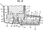
- the canister unit 14 comprises a pressurised canister 14a having a metering valve (see reference numeral 50, FIGURE 4F ) at its leading or business end and a dose counter module (see reference numeral 14b, FIGURE 4 ) mounted on the leading (valve) end of the canister 14a.
- the dose counter module 14b is as described and shown in WO-A-2004/001664 supra.
- the canister 14a contains a pressurised medicinal aerosol formulation, as known in the art and mentioned briefly hereinabove.
- a patient in need of a metered dose of the medicinal aerosol formulation places his or her lips on the mouthpiece 3 of the housing 1 and then concurrently inhales and, with their finger(s), depresses the canister unit 14 into the housing 1 (arrow F, FIGURE 1 ) to cause the metering valve 50 to release a metered dose of the medicinal formulation from the canister unit 14 for entrainment in the inspiratory airflow produced by the patient for deposition in their lungs.
- the depression of the canister unit 14 into the housing 1 also results in the dose counter module 14b recording the release of the dose and showing the number of metered doses left in the canister 14a.
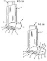
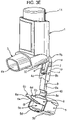
- a dust cap 5 is attached to the housing 1 by a telescopic strap 2 comprising first 7 and second 8 components.
- the first component 7 is attached at one end to the housing 1 by a hinge 9 and has a pin 11 at the opposite end to the housing 1.
- One end of the second component 8 is attached to the dust cap 5 by a second hinge 10.
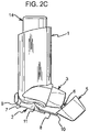
- the second component 8 comprises a linear slot 12, in which the pin 11 of the first component 7 is held captive. As shown in FIGURES 2A-2D , although captive within the slot 12, the pin 11 is free to move along its length and thus the two components 7, 8 are capable of relative sliding motion along the length of the slot 12 between a contracted position, with a maximum overlap of the components 7, 8, and an extended position, with a minimum overlap of the components 7, 8.
- the user pulls it away from the mouthpiece 3 with sufficient force to overcome a snap-fit connection therebetween (not shown), thereby extending the telescopic strap 2 to its extended position. Then, the telescopic strap 2 is pivoted at hinges 9, 10, swinging the dust cap 5 clear of the mouthpiece 3 so that it does not obstruct the mouthpiece 3 so that the pMDI is able to be actuated as described above.
- the user moves the telescopic strap 2 about the hinges 9, 10 so that the dust cap 5 is repositioned in front of the mouthpiece 3 and is then pushed towards it, compressing the telescopic strap 2 towards its contracted position.
- the snap-fit connection reconnects.
- Side walls 4 may be provided to substantially prevent relative rotational movement of the components 7, 8 about the pin 11.
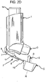
- a restricting member 6 for restricting movement of the canister unit 14 in the housing 1 when the cap 5 is mounted on the mouthpiece 3 such that inadvertent firing and counting cannot take place.
- the restricting member 6 is in the form of an arm or prong structure comprising a pair of spaced apart arms 6a, 6b.
- the arms 6a, 6b extend into the housing 1 through the lower open end 4b to straddle the stem block (see reference numeral 18, FIGURE 4 ) for the valve stem to sit underneath the dose counter module 14b at the leading end of the canister unit 14 (as shown in FIGURES 3F and 4F ).
- the arms 6a, 6b prevent the canister unit 14 being depressed sufficiently in the housing 1 to either (a) cause the dose counter module 14b to record a dose release event, or (b) cause the metering valve 50 to open for release of a metered dose of the medicament formulation.
- the arms 6a, 6b thus prevent inadvertent counting and firing when the dust cap 5 is mounted on the mouthpiece 3, which is nearly all the time as the dust cap 5 is only removed from the mouthpiece 3 when the patient needs a dose of the medicament formulation.
- Such inadvertent counting and firing might occur, for example, if the arms 6a, 6b were not present, during shipping of the pMDI from the manufacturer to the distributor, or when the pMDI is in a patient's pocket or handbag, or even as a result of a person fiddling/playing with the pMDI. Wastage of the medicinal formulation is therefore reduced.
- the dose counter module 14b is adapted to record release of a metered dose from the canister 14a after depression of the canister unit 14 into the housing by a distance which is less than that required for opening of the metering valve 50.
- the dose counter module is set-up for a 'count-not-fire' event, rather than a 'fire-not-count' event, if the pMDI is not used properly. This is because it is preferable for the dose counter display to show that there are less doses left than are actually available than vice-versa. However, it is not easy to depress the canister unit 14 only far enough to cause a 'count-not-fire' event.
- the arms 6a, 6b prevent 'count-not-fire' events occurring while the dust cap 5 is on.
- the dust cap 5 can be used with existing pMDI housings. Moreover, the profile of the inhalation airflow through the housing 1, which flows into the housing 1 through the upper open end 4a and out of the housing 1 through the lower open end 4b, is unaffected by the provision of the restricting member 6, since it requires no change to the housing and is removed from the housing prior to use of the pMDI. Consequently, the pharmaceutical performance of the pMDI is unaffected by the provision of the restricting member 6 avoiding the need to obtain new regulatory approval for an existing pMDI product using the new dust cap 5.
- cap 5 with the telescopic strap 2 provides the cap 5 with the ability to be manoeuvred onto and off the mouthpiece 3 despite it carrying the restricting member 6.
- the dust cap 5 and the strap 2 are moulded from polypropylene (PP), although, of course, other materials, in particular plastics materials, and forming techniques, may be used.
- PP polypropylene
- the hinges 9, 10 are so-called "living hinges”.
- the cap 5 is integrally formed with the restricting member 6 and the second component 8 of the strap.
- the first strap component 7 may be formed separately and then assembled to the second strap component 8.
- the strap 2 may be integrally formed with the first strap component 7.
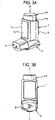
- FIGURES 3A-3J show a pMDI which corresponds to the pMDI described above with reference to FIGURES 1 and 2 in all respects bar some of the structure of the dust cap 5.
- the dust cap 5 has a restricting member 6 in the form of an arm structure comprising a pair of arm members 6a, 6b.
- the free ends of each arm member 6a, 6b are configured as clips 6c, 6d which, when the cap 5 is mounted on the mouthpiece 3, clip to a step 20 (see also FIGURE 4 ) in the base surface of the housing 1 which supports the stem block (reference 18, FIGURE 4 ).
- the clips 6c, 6d are formed by providing the free ends of the arm members 6a, 6b as a lollipop profile.
- the leading end of the canister unit 14 will push down on the upper surfaces 6e, 6f of the arms 6a, 6b which, as shown schematically in FIGURE 3F , have a tapered or ramp profile. More particularly, when the cap 5 is located on the mouthpiece 3, as in FIGURE 3F , the upper surfaces 6e, 6f of the cap arms 6a, 6b taper upwardly in the outward or dispensing direction (arrow B).
- the first component 7 of the telescopic strap 2 has a distal track member 7a with opposed side walls 4. At the distal end of the track member 7a the side walls 4 are bridged by a bridging element 4c. At the proximal end of the first component 7 there is a hinge member 7b which is secured to the housing 1. The track and hinge members 7a, 7b are hinged together by the hinge 9 whereby the track member 7a is hingable about the hinge member 7b.
- this has a proximal slide member 8a which is linearly slidable in the track member 7a and guided in its linear stroke by the side walls 4.
- the slide member 8a has a resilient finger 8m at its proximal end which presents a stop element 8b which engages with the bridging element 4c to demark the extended position of the strap 2 and to keep the slide member 8a captive in the track member 7a.
- a hinge member 8c hinged to the slide member 8a through the hinge 10.
- the hinge member 8c of the second component 8 is carried by the dust cap 5.
- FIGURES 3G and 3H are schematic, fragmentary plan views of the telescopic strap 2 showing in greater detail the strap 2 in its extended and contracted configurations, respectively.
- FIGURE 3G there is shown the engagement of the stop element 8b with the bridging element 4c to demark the extended position.
- FIGURE 31 is a cross-sectional view of the stop element 8b taken on line 31-31 in FIGURE 3H .
- the stop element 8b has a saw-tooth profile and this enables the slide member 8a to be assembled to the track member 7a by sliding of the proximal end of the slide member 8a under the bridging element 4c at the distal end of the track member 7a.
- the resilience of the finger 8m enables the stop member 8b to go under the bridging element 4c when pushed towards the hinge member 7b until it clears the bridging element 4c whereupon the finger 8m biases the stop element 8b upwardly so that it will abut the bridge element 4c when the slide member 8a is moved in the opposite direction.
- FIGURE 3G also shows that the hinge member 7b has an aperture 7c therethrough for receiving therein a stud (not shown) on the rear 1r side of the housing 1 to connect the hinge part 7b to the housing 1, as shown in FIGURES 3A-3E .
- the proximal end of the slide member 8a is configured as a trident with the stop element 8b being on the middle finger 8m thereof.
- the outer fingers 8d, 8e of the trident are resilient fingers and on their outer surface which faces the opposing side wall 4 there is provided an elongate slot 8f, 8g, a schematic side view of which is shown in FIGURE 3J with arrow S indicating the sliding direction of the slide member 8a on the track member 7a.
- the outer surfaces of the side walls 4 facing the slide member 8a are each provided with an elongate rib 7d, 7e of complementary shape and dimension to the slots 8f, 8g in the outer fingers 8d, 8e of the trident.
- the slots 8f, 8g on the outer fingers 8d, 8e snap-fit with the ribs 7d, 7e to securably, releasably fasten the strap 2 in the contracted position.
- This fastening mechanism may be the sole fastening mechanism (other than the clips 6c, 6d) for securing the dust cap 5 on the mouthpiece 3.
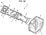
- FIGURES 3K-3M show the dust cap 5 and telescopic strap 2 arrangement of FIGURES 3A-3J , but with the first component 7 of the strap 2 incorporating some modifications thereto.
- the aperture 7c in the hinge member 7b is provided with a slot 7s in its boundary wall.
- the slot 7s provides the aperture 7c with greater flexibility when receiving the stud (not shown) for assembly of the strap 2 to the housing 1. The aperture 7c is therefore unlikely to split.
- the track member 7a is provided with raised features 7t underneath the bridging element 4c. These are added to minimise the flexibility of the slide member 8a of the second component 8 of the strap 2 so as to make it harder for the first and second components 7, 8 of the strap 2 to be disassembled. That is to say, the raised features 7t increase the force needed for disassembly to avoid accidental separation by the user.
- the raised features 7t are disposed so as to be underneath the resilient finger 8m to inhibit downward movement thereof. This therefore makes it more difficult for the stop element 8b to be slid back underneath the bridging element 4c for disassembly of the strap 2.
- the raised features 7t present an inclined lead-in surface 7u.
- the bridging element 4c includes a reinforcing rib 7v to increase robustness.
- the strap for the dust cap 5 is made from an elastic stretchable material, for example knitted elastic.
- the strap can be elastically extended to permit the user to remove or reapply the dust cap 5 and its flexibility allows the dust cap 5 to be easily positioned clear of the mouthpiece 3 whilst the pMDI is in use.
- FIGURE 4 is a schematic view of a pMDI which corresponds closely to the pMDI described with reference to FIGURES 3A-3J .
- a scrap detail of the lower part of the housing 1 is shown to reveal the base surface in which the step 20 is formed and from which the stem block 18 for the valve stem (118, FIGURE 4F ) projects upwardly.
- the stem block 18 has a spray orifice 18a oriented towards the lower open end 4b in the mouthpiece 3 whereby the metered dose fired from the canister unit 14 on depression thereof into the housing 1 is directed out of the mouthpiece 3.
- FIGURE 4 further shows the dose counter module 14b mounted on the leading (valve) end of the canister unit 14.
- the dose counter module 14b has a display window 14c which displays the number of metered doses of the medicament formulation left in the canister 14a, as described in WO-A-2004/001664 supra.
- the housing 1 has a cut-out or window 1c through which the patient can see the dose counter display 14c.
- the dose counter module 14b has a counting mechanism which is driven through a rack-and-pinion mechanism.
- FIGURE 4 shows the rack 30 which also projects upwardly from the housing base surface. The rack is slidingly received in an aperture (not shown) in the leading face of the dose counter module 14b.
- the rack drives a pinion (not shown) in the dose counter module 14b and the rotary movement of the pinion causes the counting mechanism to decrement the number displayed in the dose counter window 14c by dose counter wheels (not shown).
- the pMDI has a dust cap 5 for detachably engaging the mouthpiece 3 which corresponds to that shown in FIGURES 3A-3J other than that it does not include a connector or strap for connecting the cap 5 to the housing 1.
- a dust cap 5 for detachably engaging the mouthpiece 3 which corresponds to that shown in FIGURES 3A-3J other than that it does not include a connector or strap for connecting the cap 5 to the housing 1.
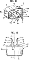
- Different views of the dust cap 5 of the fourth embodiment are shown in FIGURES 4A-4E .
- the arms 6a, 6b forming the restricting member 6 are interconnected along part of their length by a strengthening rib 6h, in order to increase their strength and rigidity.
- a strengthening rib 6h the configuration of the free ends of the arms 6a, 6b as clips 6c, 6d which engage the step 20 is advantageous, since if the canister unit 14 is moved downwards in the housing 1, for instance if the pMDI is dropped, it pushes the arms 6a, 6b towards the step 20, so as to increase the gripping force of the clips 6c, 6d to ensure that the dust cap 5 and restricting member 6 do not eject from the mouthpiece 3.
- FIGURE 4F shows schematically how the restricting member 6 prevents actuation of the pMDI in the same way described for the pMDI with reference to FIGURE 3F .
- the arms 6a, 6b sit underneath the dose counter module 14b to prevent it moving towards the base 32 of the housing 1 the required distance for the valve stem 118 to be depressed into the canister 14a for release of the metered dose nor for the rack 30 to drive the pinion for decrementing the dose counter display 14c.
- a clip 19a is provided on the dust cap 5 to engage a slot 19b on the outer surface of the mouthpiece 3 to provide additional retention of the dust cap 5 on the housing 1.
- none of the clips 6c, 6d, 19a prevent the dust cap 5 from being fairly easily removed from the housing 1 by a user.
- the restricting member 6 is asymmetrically arranged in the dust cap 5, inasmuch as being located closer to the cap bottom than to the cap top ( FIGURES 4A , 4C , 4D , 4F ). If the dust cap 5 is mounted on the mouthpiece 3 in an inverted orientation, then the canister unit 14 may not be able to be inserted properly into the housing 1. Accordingly, the dust cap 5 may be provided with indicia indicating the correct orientation of the cap 5, for example by providing indicia on the cap outer surface, for instance on its front face 5a.
- the restricting member 6 is also provided with lateral alignment ribs (wings) 21 to prevent it from being inserted at more than a prescribed angle to the mouthpiece 3, whereupon one of the arms 6a, 6b might be inserted into a hollow 18b in the stem block 18 or be otherwise obstructed by the components of the pMDI.
- the alignment ribs 21 help to ensure that the dust cap 5 is mounted on the mouthpiece 3 so that the arms 6a, 6b straddle the stem block 18 with the clips 6c, 6d clipping into engagement with the step 20.
- the clips 6c, 6d of the restricting member 6 could be reconfigured such that they clip onto the stem block 18 to retain the cap 5 in place for blocking movement of the canister unit 14 in the housing 1 in the firing direction.
- the clips 6c, 6d of the restricting member 6 could be replaced with laterally extending clips which, when the dust cap 5 is mounted on the mouthpiece 3, clip behind a sidewall 1s ( FIG. 4 ) in the housing 1. Such lateral clips could also be used in conjunction with the clips 6c, 6d.
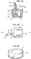
- FIGURES 4G and 4H in addition to the restricting member 6, the dust cap 5 of FIGURES 4-4F is provided with a pair of supplementary clips 100, only the clip end 101 of one of the clips 100 being shown in FIGURES 4G and 4H.
- FIGURE 4G is a plan view of the clip end 101
- FIGURE 4H is an end view on arrow N in FIGURE 4G .
- the clips 100 have resilient legs 103 which extend outwardly from the dust cap 5 on different sides of the central axis R-R ( FIG. 4 ). As will be understood from FIGURE 4G in conjunction with FIGURE 4 , when the dust cap 5 is mounted to the mouthpiece 3, the clips 100 extend through the opening 4b and the resilient legs 103 bias the clip ends 101 outwardly so they clip behind the sidewall 1s of the housing 1.
- the clip ends 101 of the clips 100 are further provided with an extension 105 having an inclined surface 107.
- the extensions 105 are configured and arranged to dispose the inclined surfaces 107 underneath the dose counter module 14b. If the canister unit 14 is moved downwardly in the housing 1 while the dust cap 5 is mounted on the mouthpiece 3, as indicated by arrow O in FIGURE 4H , the leading end of the dose counter module 14b will engage the inclined surfaces 107 and bias the clip ends 101 in the direction of arrow P resulting in the clip ends 101 clipping even more firmly behind the sidewall 1s of the housing 1.
- the clips 100 provide supplementary protection against the dust cap 5 being ejected from the mouthpiece 3 by downward movement of the canister unit 14 in the housing 1, e.g. caused by the user or dropping of the pMDI.
- the clips 100 could be used as a restricting member in their own right, that is to say, in place of the restricting member 6.
- the clips 100 could also be used as a supplement to a restricting member which does not incorporate clips, for instance with the restricting member 6 of FIGURES 4-4F where the restricting member 6 is not provided with the clips 6c, 6d.
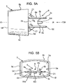
- FIGURES 5A and 5B respectively show plan and front views of a dust cap 5 in accordance with a first embodiment of the invention which corresponds in nearly all respects to the dust cap 5 in the pMDI shown in FIGURES 4-4F .
- the asymmetrically mounted restricting member 6 is further provided with a middle arm 6m projecting from the strengthening rib 6h between the outer arms 6a, 6b, thereby forming a trident configuration.
- the length of the middle arm 6m is shorter than the outer arms 6a, 6b.
- the dust cap 5 of the first embodiment has a hollow body 5b which is of a shell form and a generally rectangular cross-sectional shape.
- the body 5b comprises the front face 5a and a side skirt 5c.
- the rear end of the side skirt 5c presents an annular lip 5d about a mouth 5e to the inner volume of the body 5b.
- the restricting member 6 extends rearwardly from an inner surface 5f of the front face 5a.
- the mouthpiece 3 of the pMDI housing 1 is of complementary shape and size to the cap body 5b whereby the cap body 5b is slidable rectilinearly over the mouthpiece 3 as a push-fit. It will also be appreciated that the mutual shapes of the cap body 5b and the mouthpiece 3 ensure that the cap 5 is non-rotatable on the mouthpiece 3.
- the cap body 5b is able to be push-fit onto the mouthpiece 3 in two different orientations of the cap 5 about its central axis R-R.
- a first, correct orientation in which the restricting member 6 is underneath the central axis R-R, as shown in FIGURES 4 and 4D , for example, the cap 5 is able to be push-fit onto the mouthpiece 3 so that the clips 6c, 6d clip to the step 20, as previously described.
- the annular lip 5d of the side skirt 5c abuts an annular surface 3a of the pMDI housing 1 about the mouthpiece 3 so that there is no gap therebetween. In this position the clips 19a, 19b will also clip together.
- the cap 5 is turned upside-down (i.e. rotated 180° about the central axis R-R) from the first, correct orientation to a second, incorrect orientation, so that the restricting member 6 is disposed above the central axis R-R, the cap 5 is still able to be push-fit onto the mouthpiece 3 so that the annular lip 5d abuts the annular housing surface 3a since the arms 6a, 6b of the restricting member 6 will straddle the stem block 18 and the strengthening rib 6h will be spaced from the stem block 18. Nonetheless, none of the clips 6c, 6d, 19a of the cap 5 will clip to their respective counterparts.
- the cap 5 will not be secured to the mouthpiece 3 as well as if in the first, correct orientation. Moreover, since there would be no gap between the annular lip 5d and the annular housing surface 3a, the user is not given an indication that the cap 5 is not correctly fitted on the mouthpiece 3.
- cap 5 could inadvertently detach from the mouthpiece 3, for instance if a downward pressure is applied to the base of the canister 14a since the leading end of the dose counter module 14b will tend to push the cap 5 outwardly by acting on the upside-down restricting member 6.
- the cap 5 of the first embodiment is adapted to alleviate this possibility through the provision of the middle arm 6m, as will be described in more detail with reference to FIGURES 6A-D .
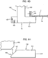
- FIGURE 6A is an enlarged front view of the stem block 18 shown in FIGURES 4 and 4F .
- FIGURE 6B schematically shows that, when the dust cap 5 of the first embodiment is in its correct angular orientation about its central axis R-R, as shown in FIGURE 5B , the middle arm 6m of the restricting member 6 slides into the hollow 18b in the stem block 18 underneath the spray orifice 18a so as not to interfere with the push-fit mounting of the cap 5 on the mouthpiece 3 so that the clips 6c, 6d engage the step 20 and the clips 19a, 19b engage. Moreover, the annular cap body lip 5d will form a flush fit with the annular housing surface 3a.
- FIGURE 6C shows that if an attempt is made to mount the cap 5 on the mouthpiece 3 in the incorrect upside-down orientation, the middle arm 6m will hit the stem block 18 above the hollow 18b. As illustrated in FIGURE 6D , this will occur before the cap 5 has been pushed onto the mouthpiece 3 far enough for the annular cap body lip 5d to meet the annular housing surface 3a so that a gap G is left therebetween. The user is therefore given a tactile and visual indication that the cap 5 is incorrectly orientated, namely:-
- the user will be prompted by these indications to orient the cap 5 into the correct orientation for installation on the mouthpiece 3.
- the cap body 5b may be provided with an extension which is offset to the central cap axis R-R, for instance the same side of the central axis R-R as the restricting member 6, and which does not interfere with mounting of the cap 5 to the mouthpiece 3 in the correct or intended cap orientation, but strikes a surface of the pMDI, e.g. the housing 1, when the cap 5 is attempted to be mounted to the mouthpiece 3 in the incorrect or unintended orientation.
- FIGURES 7A-B and 8A-B illustrate embodiments of the invention provided with such extensions.
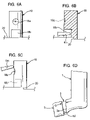
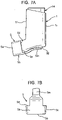
- FIGURES 7A-B show a second embodiment of the invention in which the cap body 5b has a resilient extension 5m which, in this particular embodiment, takes the form of a tongue, as will be understood from the underneath view of the cap 5 in FIGURE 7B .
- the extension 5m projects from the side skirt 5c of the cap body 5b and, in the correct cap orientation, slides underneath the pMDI housing 1, as shown in FIGURE 7A .
- the extension is shaped to conform to the base 32 of the housing 1 and the resilience of the extension 5m biases it towards the housing base 32 so that it does not protrude from the housing 1.
- the positioning and length of the extension 5m is such that, if an attempt is made to slide the dust cap 5 over the mouthpiece 3 in its incorrect orientation, the extension will hit a front face 1f of the housing 1 before the cap 5 is properly mounted on the mouthpiece 3. Again, an indication of this is given by the annular cap body lip 5d being spaced from the annular housing surface 3a when the extension 5m strikes the housing front face 1f.
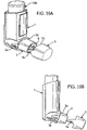
- FIGURES 8A and 8B illustrate a third embodiment of the invention in which the cap 5 corresponds to that shown in FIGURES 7A and 7B other than the resilient extension being in the form of a frame 5n, as shown in the underneath plan view of FIGURE 8B .
- FIGURES 9A and 9B there is shown another dust cap 5 in accordance with a fourth embodiment of the invention which corresponds to that of FIGURES 4-4F , and optionally the first embodiment of FIGURES 5A and 5B , but where the annular cap body lip 5d lies on an inclined plane P-P which extends orthogonally to the central axis R-R - along which the cap 5 is translated onto the mouthpiece 3 as in the other embodiments involving use of a dust cap 5, whether with a strap or not - but which is oriented at an inclined angle ⁇ to the central axis R-R.
- the annular housing surface 3a is of complementary form to the annular lip 5d so that, when the cap 5 is oriented correctly about its central axis R-R, as shown in FIGURE 9A , the cap 5 can be moved along its central axis R-R onto the mouthpiece 3 until the lip 5d forms a flush fit with the annular housing surface 3a so that there is no gap therebetween.
- the clips 6c, 6d of the restricting member 6 engage with the step 20 in the housing, as do the clips 19a, 19b on the cap 5 and housing 1.
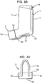
- FIGURES 10A and 10B there is shown a dust cap 5 in accordance with a fifth embodiment of the invention.
- the annular cap body lip 5d includes a tongue section 5s for receipt in a complementary groove section 3s in the annular housing surface 3a about the mouthpiece 3.
- the groove and tongue sections 3s, 5s can only fit together when the cap 5 is pushed over the mouthpiece 3 in the correct orientation for proper placement of the restricting member 6.
- the tongue and groove feature guides the user to place the cap 5 on the mouthpiece 3 correctly.
- the groove and tongue sections 3s, 5s are asymmetric.
- they could be one of a pair of such sections, on diametrically opposed sides of the cap 5 and the mouthpiece 3, since they would still only be able to mate if the cap 5 were correctly oriented due to the asymmetrical nature of these sections.
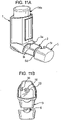
- FIGURES 11A and 11B show a dust cap 5 of an sixth embodiment of the invention in which the annular housing surface 3a is provided with a tongue section 3t, while the cap body lip 5d has a complementary groove section 5t which is only able to receive the tongue section 3t when the cap 5 is pushed onto the mouthpiece 3 in the correct cap orientation.
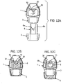
- FIGURE 12A-12C show a dust cap 5 of a seventh embodiment of the invention in which the restricting member 6 is configured and arranged so that it is only insertable through the mouthpiece 3 of the housing 1 to its full extent when the cap 5 is oriented correctly. More particularly, the restricting member is given an asymmetric configuration whereby, in the correct orientation of the cap 5, the arm 6a of the restricting member 6 fits between the stem block 18 and the rack 30, and whereby, in the incorrect (inverted) orientation of the cap 5, the arm 6b of the restricting member 6 cannot fit between the stem block 18 and the rack 30. Consequently, in the incorrect orientation of the cap 5, the cap 5 is placed outwardly from the mouthpiece 3, as shown in FIGURE 12C .
- the present invention is equally applicable where the canister unit 14 does not include the dose counter module 14b. That is to say, the canister unit 14 may simply be the pressurised canister 14a with its valve 50. Alternatively, some other accessory or cap or module may be mounted to the leading end of the canister 14a in place of the dose counter module 14b.
- the medicament contained in the canister unit 14 may for the treatment of mild, moderate or severe acute or chronic symptoms or for prophylactic treatment.
- the medicament is suitably for treating respiratory diseases, e.g. asthma, chronic obstructive pulmonary disease (COPD), although may be for other therapeutic indications, e.g. treating rhinitis.
- respiratory diseases e.g. asthma, chronic obstructive pulmonary disease (COPD)
- COPD chronic obstructive pulmonary disease
- Exemplary medicaments and formulations are disclosed in WO-A-2005/087299 from page 38, last paragraph to page 41, second paragraph (inclusive).
Applications Claiming Priority (4)
| Application Number | Priority Date | Filing Date | Title |
|---|---|---|---|
| GB0405397A GB0405397D0 (en) | 2004-03-10 | 2004-03-10 | An inhaler |
| GB0420538A GB0420538D0 (en) | 2004-09-15 | 2004-09-15 | A dispensing device |
| PCT/GB2005/000926 WO2005087299A1 (en) | 2004-03-10 | 2005-03-10 | A dispensing device |
| EP05717987.1A EP1725285B1 (en) | 2004-03-10 | 2005-03-10 | A dispensing device with restricting member |
Related Parent Applications (2)
| Application Number | Title | Priority Date | Filing Date |
|---|---|---|---|
| EP05717987.1A Division EP1725285B1 (en) | 2004-03-10 | 2005-03-10 | A dispensing device with restricting member |
| PCT/GB2005/000926 Previously-Filed-Application WO2005087299A1 (en) | 2004-03-10 | 2005-03-10 | A dispensing device |
Publications (2)
| Publication Number | Publication Date |
|---|---|
| EP3662948A1 EP3662948A1 (en) | 2020-06-10 |
| EP3662948B1 true EP3662948B1 (en) | 2022-11-09 |
Family
ID=34961413
Family Applications (2)
| Application Number | Title | Priority Date | Filing Date |
|---|---|---|---|
| EP19196452.7A Active EP3662948B1 (en) | 2004-03-10 | 2005-03-10 | A dispensing device |
| EP05717987.1A Active EP1725285B1 (en) | 2004-03-10 | 2005-03-10 | A dispensing device with restricting member |
Family Applications After (1)
| Application Number | Title | Priority Date | Filing Date |
|---|---|---|---|
| EP05717987.1A Active EP1725285B1 (en) | 2004-03-10 | 2005-03-10 | A dispensing device with restricting member |
Country Status (9)
| Country | Link |
|---|---|
| US (2) | US8397714B2 (pt) |
| EP (2) | EP3662948B1 (pt) |
| JP (1) | JP4940127B2 (pt) |
| AU (1) | AU2005221383B2 (pt) |
| BR (1) | BRPI0508578B8 (pt) |
| CA (1) | CA2559080A1 (pt) |
| ES (2) | ES2765048T3 (pt) |
| PL (1) | PL1725285T3 (pt) |
| WO (1) | WO2005087299A1 (pt) |
Families Citing this family (81)
| Publication number | Priority date | Publication date | Assignee | Title |
|---|---|---|---|---|
| SE0303029D0 (sv) | 2003-11-17 | 2003-11-17 | Astrazeneca Ab | Inhaler cap strap |
| AU2005221383B2 (en) | 2004-03-10 | 2010-07-22 | Glaxo Group Limited | A dispensing device |
| FR2871450B1 (fr) * | 2004-06-14 | 2006-09-22 | Valois Sas | Dispositif de distribution de produit fluide |
| GB0518355D0 (en) * | 2005-09-08 | 2005-10-19 | Glaxo Group Ltd | An inhaler |
| GB0518770D0 (en) * | 2005-09-14 | 2005-10-26 | Glaxo Group Ltd | A closure for a dispensing device |
| US20070181119A1 (en) * | 2006-02-08 | 2007-08-09 | Weinstein Robert E | Inhaler Device |
| JP5241714B2 (ja) | 2006-07-07 | 2013-07-17 | プロテウス デジタル ヘルス, インコーポレイテッド | スマートな非経口送達システム |
| US8141550B2 (en) | 2006-08-01 | 2012-03-27 | Trudell Medical International | Dispensing device |
| EP2099514A2 (en) * | 2006-12-22 | 2009-09-16 | Schering Corporation | Dose counter mechanism |
| US9125979B2 (en) | 2007-10-25 | 2015-09-08 | Proteus Digital Health, Inc. | Fluid transfer port information system |
| WO2009067463A1 (en) | 2007-11-19 | 2009-05-28 | Proteus Biomedical, Inc. | Body-associated fluid transport structure evaluation devices |
| EP2230934B8 (en) | 2007-12-14 | 2012-10-24 | AeroDesigns, Inc | Delivering aerosolizable food products |
| EP2077132A1 (en) | 2008-01-02 | 2009-07-08 | Boehringer Ingelheim Pharma GmbH & Co. KG | Dispensing device, storage device and method for dispensing a formulation |
| WO2009112539A2 (en) * | 2008-03-12 | 2009-09-17 | Glaxo Group Limited | A closure |
| WO2009128491A1 (ja) * | 2008-04-17 | 2009-10-22 | 帝人ファーマ株式会社 | 定量噴霧式吸入器用吸入補助器具 |
| DE102008027147A1 (de) * | 2008-06-02 | 2009-12-03 | Ing. Erich Pfeiffer Gmbh | Austragvorrichtung für Medien |
| US20110232636A1 (en) * | 2008-12-18 | 2011-09-29 | Koninklijke Philips Electronics, N.V. | Valved holding chamber and mask therefor |
| WO2010075240A1 (en) * | 2008-12-22 | 2010-07-01 | Novartis Ag | Medical device |
| US10011906B2 (en) | 2009-03-31 | 2018-07-03 | Beohringer Ingelheim International Gmbh | Method for coating a surface of a component |
| EP3508239B1 (de) | 2009-05-18 | 2020-12-23 | Boehringer Ingelheim International GmbH | Adapter, inhalationseinrichtung und zerstäuber |
| US10016568B2 (en) | 2009-11-25 | 2018-07-10 | Boehringer Ingelheim International Gmbh | Nebulizer |
| WO2011064163A1 (en) | 2009-11-25 | 2011-06-03 | Boehringer Ingelheim International Gmbh | Nebulizer |
| UA107097C2 (en) | 2009-11-25 | 2014-11-25 | Бьорінгер Інгельхайм Інтернаціональ Гмбх | Dispenser |
| JP5841951B2 (ja) | 2010-02-01 | 2016-01-13 | プロテウス デジタル ヘルス, インコーポレイテッド | データ収集システム |
| CN102905612A (zh) | 2010-02-01 | 2013-01-30 | 普罗秋斯数字健康公司 | 双腕式数据采集系统 |
| GB201006759D0 (en) * | 2010-04-23 | 2010-06-09 | 3M Innovative Properties Co | An inhaler |
| EP2585151B1 (en) | 2010-06-24 | 2018-04-04 | Boehringer Ingelheim International GmbH | Nebulizer |
| WO2012130757A1 (de) | 2011-04-01 | 2012-10-04 | Boehringer Ingelheim International Gmbh | Medizinisches gerät mit behälter |
| US9827384B2 (en) | 2011-05-23 | 2017-11-28 | Boehringer Ingelheim International Gmbh | Nebulizer |
| WO2013152894A1 (de) | 2012-04-13 | 2013-10-17 | Boehringer Ingelheim International Gmbh | Zerstäuber mit kodiermitteln |
| EP2900778B1 (en) | 2012-09-27 | 2017-05-10 | 3M Innovative Properties Company | A dispensing assembly |
| GB201304784D0 (en) | 2013-03-15 | 2013-05-01 | Euro Celtique Sa | Dispenser |
| WO2015018904A1 (en) | 2013-08-09 | 2015-02-12 | Boehringer Ingelheim International Gmbh | Nebulizer |
| ES2836977T3 (es) | 2013-08-09 | 2021-06-28 | Boehringer Ingelheim Int | Nebulizador |
| USD783807S1 (en) * | 2013-10-07 | 2017-04-11 | Teva Pharmaceutical Industries Limited | Respiratory apparatus |
| AU355051S (en) * | 2013-10-07 | 2014-04-16 | Teva Uk Ltd | Respiratory apparatus |
| AU355166S (en) * | 2013-10-07 | 2014-04-28 | Teva Uk Ltd | Respiratory apparatus |
| USD783159S1 (en) * | 2013-10-07 | 2017-04-04 | Teva Pharmaceutical Industries Limited | Respiratory apparatus |
| AU355177S (en) * | 2013-10-07 | 2014-04-29 | Teva Uk Ltd | Respiratory apparatus |
| TWD174570S (zh) * | 2013-10-07 | 2016-03-21 | 泰瓦英國有限公司 | 呼吸裝置 |
| AU355165S (en) * | 2013-10-07 | 2014-04-28 | Teva Uk Ltd | Respiratory apparatus |
| AU355175S (en) * | 2013-10-07 | 2014-04-29 | Teva Uk Ltd | Respiratory apparatus |
| USD782653S1 (en) * | 2013-10-08 | 2017-03-28 | Teva Pharmaceutical Industries Limited | Respiratory apparatus |
| USD783804S1 (en) * | 2013-10-08 | 2017-04-11 | Teva Pharmaceutical Industries Limited | Respiratory apparatus |
| USD783147S1 (en) * | 2013-10-08 | 2017-04-04 | Teva Pharmaceutical Industries Limited | Respiratory appartus |
| USD783148S1 (en) * | 2013-10-08 | 2017-04-04 | Teva Pharmaceutical Industries Limited | Respiratory apparatus |
| AU355204S (en) * | 2013-10-08 | 2014-05-02 | Teva Uk Ltd | Respiratory apparatus |
| USD783149S1 (en) * | 2013-10-08 | 2017-04-04 | Teva Pharmaceutical Industries Limited | Respiratory apparatus |
| USD782648S1 (en) * | 2013-10-08 | 2017-03-28 | Teva Pharmaceutical Industries Limited | Respiratory apparatus |
| AU355164S (en) * | 2013-10-08 | 2014-04-28 | Teva Uk Ltd | Respiratory apparatus |
| AU355056S (en) * | 2013-10-08 | 2014-04-16 | Teva Uk Ltd | Respiratory apparatus |
| USD783152S1 (en) * | 2013-10-08 | 2017-04-04 | Teva Pharmaceutical Industries Limited | Respiratory apparatus |
| AU355168S (en) * | 2013-10-08 | 2014-04-29 | Teva Uk Ltd | Respiratory apparatus |
| AU355172S (en) * | 2013-10-08 | 2014-04-29 | Teva Uk Ltd | Respiratory Apparatus |
| AU355203S (en) * | 2013-10-08 | 2014-05-01 | Teva Uk Ltd | Respiratory apparatus |
| USD782647S1 (en) * | 2013-10-08 | 2017-03-28 | Teva Pharmaceutical Industries Limited | Respiratory apparatus |
| USD783155S1 (en) * | 2013-10-08 | 2017-04-04 | Teva Pharmaceutical Industries Limited | Respiratory apparatus |
| USD783154S1 (en) * | 2013-10-08 | 2017-04-04 | Teva Pharmaceutical Industries Limited | Respiratory apparatus |
| AU356104S (en) * | 2013-11-29 | 2014-06-24 | Norton Waterford Ltd | Respiratory apparatus |
| AU356105S (en) * | 2013-11-29 | 2014-06-24 | Norton Waterford Ltd | Respiratory apparatus |
| US10238764B2 (en) | 2014-08-19 | 2019-03-26 | Vapium Inc. | Aromatherapy vaporization device |
| US11065402B2 (en) * | 2014-02-04 | 2021-07-20 | Gseh Holistic, Inc. | Aromatherapy vaporization device |
| US10195374B2 (en) * | 2014-05-07 | 2019-02-05 | Boehringer Ingelheim International Gmbh | Container, nebulizer and use |
| WO2015169430A1 (en) | 2014-05-07 | 2015-11-12 | Boehringer Ingelheim International Gmbh | Nebulizer |
| KR102492824B1 (ko) | 2014-05-07 | 2023-01-30 | 베링거 인겔하임 인터내셔날 게엠베하 | 분무기, 표시 디바이스 및 컨테이너 |
| CN106535970A (zh) * | 2014-05-28 | 2017-03-22 | 赛诺菲股份有限公司 | 用于药物输送装置的计数器机构的组件和药物输送装置 |
| US10561806B2 (en) * | 2014-10-02 | 2020-02-18 | Mannkind Corporation | Mouthpiece cover for an inhaler |
| KR101990017B1 (ko) | 2014-11-26 | 2019-06-17 | 벡투라 딜리버리 디바이시스 리미티드 | 건조 분말 흡입기 |
| DE102014118248A1 (de) * | 2014-12-09 | 2016-06-09 | Alfred Von Schuckmann | Handgerät zur Ausgabe einer pharmazeutischen Substanz |
| US10105561B2 (en) * | 2015-06-30 | 2018-10-23 | Kronebusch Industries, Llc | Nozzle cap for fire extinguisher |
| EP3374011B1 (en) | 2015-11-09 | 2023-07-19 | Boehringer Ingelheim International GmbH | System comprising nebulizer and container |
| GB2544477A (en) * | 2015-11-16 | 2017-05-24 | 3M Innovative Properties Co | Improvements in or relating to medical actuators |
| USD837365S1 (en) * | 2016-06-16 | 2019-01-01 | Koninklijke Philips N.V. | Handheld secretion clearance device |
| CA3043593C (en) | 2016-11-15 | 2021-04-20 | Eli Lilly And Company | Medication delivery device with mechanical locking system |
| US11715390B2 (en) | 2016-12-16 | 2023-08-01 | Koninklijke Philips N.V. | Training device for an inhaler, and an inhaler |
| USD833064S1 (en) * | 2017-08-29 | 2018-11-06 | VMR Products, LLC | Cartridge for a vaporizer |
| EP3806939B1 (en) * | 2018-06-13 | 2024-04-10 | Puff-Ah Pty Ltd | Apparatus for use in delivering respiratory drugs |
| EP3650066A1 (en) | 2018-11-12 | 2020-05-13 | Jagotec AG | Inhaler jacket with cap attachment |
| USD995752S1 (en) * | 2020-02-14 | 2023-08-15 | Aptar France Sas | Inhaler |
| USD983961S1 (en) * | 2020-02-14 | 2023-04-18 | Aptar France Sas | Inhaler |
| WO2023126964A1 (en) * | 2021-12-30 | 2023-07-06 | Aerodel Technologies Llp | An enhancer for delivery of aerosol from a pressurized metered dose inhaler (pmdi) |
Family Cites Families (151)
| Publication number | Priority date | Publication date | Assignee | Title |
|---|---|---|---|---|
| US389707A (en) * | 1888-09-18 | Paul kottgen | ||
| US384689A (en) | 1888-06-19 | Chain-grip for cable roads | ||
| US197890A (en) * | 1877-12-04 | Improvement in bottle-stoppers | ||
| US834679A (en) * | 1905-02-11 | 1906-10-30 | Charles Carter Newton | Stopper for bottles, tubes, containers, and the like. |
| US1814343A (en) * | 1929-07-31 | 1931-07-14 | Milton F Smith | Closure fastener |
| US2052260A (en) * | 1935-12-18 | 1936-08-25 | Tomita Rioe | Closure for containers |
| US2627996A (en) | 1950-11-03 | 1953-02-10 | Dorner Katherina | Sanitary container |
| DE1250055B (de) * | 1962-03-02 | 1967-09-14 | Benger I abotatories Limited Hol mes Chapel Cheshire (Großbritannien) | Vornch tung zum Verabreichen eines durch Inhalieren einzunehmenden Medikamentes |
| GB1044627A (en) | 1962-03-02 | 1966-10-05 | Benger Lab Ltd | Improvements in or relating to dispensing heads for pressurised dispensing containers |
| US3255928A (en) | 1963-05-20 | 1966-06-14 | Clark Mfg Co J L | Tamperproof closure for dispensing container |
| US3191867A (en) * | 1963-10-23 | 1965-06-29 | Revlon | Atomizer |
| US3429310A (en) | 1966-05-05 | 1969-02-25 | Sterling Drug Inc | Aerosol inhalating device |
| GB1188003A (en) * | 1967-07-04 | 1970-04-15 | Sterwin Ag | Improvements in or relating to Aerosol Dispensers. |
| US3622053A (en) * | 1969-12-10 | 1971-11-23 | Schering Corp | Aerosol inhaler with flip-up nozzle |
| NO134730L (pt) * | 1971-07-19 | 1900-01-01 | ||
| US3927806A (en) | 1972-09-07 | 1975-12-23 | Philip Meshberg | Applicator for attachment to a spray mist dispenser |
| US3904088A (en) | 1972-10-18 | 1975-09-09 | Sr Benjamin K Milbourne | Safety closure for an aerosol container |
| US3830224A (en) | 1972-12-19 | 1974-08-20 | Vanzetti Infrared Computer Sys | Means for detecting changes in the temperature of the skin |
| US3994421A (en) * | 1975-09-29 | 1976-11-30 | American Cyanamid Company | Unitary therapeutic aerosol dispenser |
| IL58720A (en) | 1979-01-11 | 1984-02-29 | Scherico Ltd | Inhalation device |
| US4429799A (en) * | 1981-01-09 | 1984-02-07 | Monarch Wine Co., Inc. | Bottle with a one-piece corking means |
| SE433443B (sv) | 1981-09-15 | 1984-05-28 | Draco Ab | Aerosolinhalationsanordning |
| SE434458B (sv) | 1981-09-21 | 1984-07-30 | Draco Ab | Aerosolutmatningsanordning |
| US4509515A (en) | 1982-02-23 | 1985-04-09 | Fisons Plc | Inhalation device |
| US4771769A (en) | 1982-12-20 | 1988-09-20 | Schering Corporation | Hand held metered spray dispenser |
| US4576157A (en) | 1983-10-24 | 1986-03-18 | Raghuprasad Puthalath K | Oral inhalation apparatus |
| GB8328808D0 (en) | 1983-10-28 | 1983-11-30 | Riker Laboratories Inc | Inhalation responsive dispensers |
| DE3340869A1 (de) | 1983-11-11 | 1985-05-23 | Ing. Erich Pfeiffer GmbH & Co KG, 7760 Radolfzell | Austragvorrichtung, insbesondere schubkolben-pumpe fuer wirkstoff-gefaesse |
| FI69962C (fi) * | 1983-12-28 | 1986-09-12 | Huhtamaeki Oy | Inhalationsanordning |
| US4644107A (en) | 1984-10-26 | 1987-02-17 | Ttc | Voice-controlled telephone using visual display |
| DE8526339U1 (pt) | 1985-09-14 | 1987-05-07 | Ing. Erich Pfeiffer Gmbh & Co Kg, 7760 Radolfzell, De | |
| FR2589756B1 (fr) | 1985-11-13 | 1988-07-29 | Valois Sa | Dispositif de securite pour vaporisateur |
| FR2605606B1 (fr) | 1986-10-23 | 1989-06-09 | Valois | Dispositif de securite et d'inviolabilite pour pulverisateur du type nasal |
| US5031610A (en) * | 1987-05-12 | 1991-07-16 | Glaxo Inc. | Inhalation device |
| US5119806A (en) | 1987-05-12 | 1992-06-09 | Glaxo Inc. | Inhalation device |
| US4944429A (en) | 1987-08-28 | 1990-07-31 | Schering Corporation | Manually-operable spray dispenser with locking mechanism |
| GB8810898D0 (en) | 1988-05-09 | 1988-06-15 | Bespak Plc | Improvements in dispensing apparatus |
| US4834083A (en) | 1988-05-12 | 1989-05-30 | Minnesota Mining And Manufacturing Company | Aerosol device |
| GB8919131D0 (en) | 1989-08-23 | 1989-10-04 | Riker Laboratories Inc | Inhaler |
| US5007419A (en) | 1989-09-25 | 1991-04-16 | Allan Weinstein | Inhaler device |
| DK544589D0 (da) * | 1989-11-01 | 1989-11-01 | Novo Nordisk As | Manuel betjent apparat til dispensering af en forudbestemt maengde af et pulverformet stof |
| GB8925707D0 (en) | 1989-11-14 | 1990-01-04 | Riker Laboratories Inc | Device |
| GB9026191D0 (en) | 1990-12-01 | 1991-01-16 | Harris Pharma Ltd | Breath actuated dispensing device |
| GB9027255D0 (en) | 1990-12-17 | 1991-02-06 | Minnesota Mining & Mfg | Closure system for inhalers |
| US5243970A (en) | 1991-04-15 | 1993-09-14 | Schering Corporation | Dosing device for administering metered amounts of powdered medicaments to patients |
| US5203323A (en) | 1991-07-02 | 1993-04-20 | Tritle Paul E | Metered dose inhaler spacer device and associated cleaning brush |
| FR2682305B1 (fr) | 1991-10-11 | 1993-12-24 | Valois | Dispositif de pulverisation ou de distribution d'une substance fluide, a actionnement mecanique. |
| GB2263873A (en) | 1992-05-29 | 1993-08-11 | Norton Healthcare Ltd | Medicament dispensing device |
| GB2264238A (en) | 1992-05-29 | 1993-08-25 | Norton Healthcare Ltd | Medicament inhalor device |
| GB9218937D0 (en) | 1992-09-08 | 1992-10-21 | Norton Healthcare Ltd | Medicament dispensing device |
| GB2272162B (en) | 1992-11-06 | 1996-10-09 | Paul Richard Yerbury | Dust proof inhaler |
| CZ287848B6 (en) | 1992-12-18 | 2001-02-14 | Schering Corp | Inhalator of powder substances |
| DE4415462C1 (de) | 1994-05-03 | 1995-08-31 | Transcoject Marketing Gmbh | Inhalator |
| GB2294506B (en) * | 1994-10-25 | 1998-02-18 | Bespak Plc | Dispensing apparatus |
| US6382463B2 (en) * | 1995-04-10 | 2002-05-07 | Dispensing Patents International Llc | Spray dispensing device with nozzle closure |
| US5564583A (en) * | 1995-05-12 | 1996-10-15 | Kelley; David J. | Portable carrier for a beverage container |
| US20040237961A1 (en) | 1995-06-08 | 2004-12-02 | Snow John Medlin | Inhalation actuated device for use with metered dose inhalers (MDIs) |
| US6672304B1 (en) | 1995-06-08 | 2004-01-06 | Innovative Devices, Llc | Inhalation actuated device for use with metered dose inhalers (MDIs) |
| US5826571A (en) | 1995-06-08 | 1998-10-27 | Innovative Devices, Llc | Device for use with metered dose inhalers (MDIS) |
| CA2229666A1 (en) * | 1995-08-18 | 1997-02-27 | Pharmasol Limited | Spray applicator |
| US7131441B1 (en) * | 1995-12-07 | 2006-11-07 | Skyepharma Ag | Inhaler for multiple dosed administration of a pharmacological dry powder |
| FR2743544B1 (fr) * | 1996-01-16 | 1998-02-20 | Valois | Dispositif de distribution de produit fluide pourvu d'une double securite |
| JP3830972B2 (ja) | 1996-02-21 | 2006-10-11 | シェーリング コーポレイション | 粉体薬剤吸入器 |
| GB2312379B (en) | 1996-04-25 | 1999-11-17 | Bespak Plc | Improved inhalers |
| GB2312848B (en) | 1996-04-26 | 1999-11-17 | Bespak Plc | Controlled flow inhalers |
| FR2750406B1 (fr) | 1996-06-28 | 1998-08-28 | Valois | Dispositif d'obturation de l'orifice de distribution d'un distributeur de produits fluides |
| GB2318737B (en) | 1996-10-30 | 2000-06-14 | Bespak Plc | Improved inhalers |
| FR2758479B1 (fr) * | 1997-01-20 | 1999-03-26 | Valois | Dispositif pour distribuer un produit fluide ou pulverulent a une distance predeterminee |
| SE9700948D0 (sv) | 1997-03-14 | 1997-03-14 | Astra Ab | Powder inhaler X |
| TW469832U (en) | 1997-03-14 | 2001-12-21 | Astra Ab | Inhalation device |
| WO1998052634A1 (en) | 1997-05-23 | 1998-11-26 | Pa Knowledge Limited | Inhaler mechanism |
| US6182665B1 (en) | 1997-06-02 | 2001-02-06 | Brigham And Women's Hospital | Maternal immune responsiveness as a predictor of pregnancy outcome |
| TW533865U (en) | 1997-06-10 | 2003-05-21 | Glaxo Group Ltd | Dispenser for dispensing medicament and actuation indicating device |
| SE9702796D0 (sv) | 1997-07-25 | 1997-07-25 | Pharmacia & Upjohn Ab | A device at a pharmaceutical container or inhaler |
| SE9704184D0 (sv) | 1997-11-14 | 1997-11-14 | Astra Ab | Inhalation device |
| DE19753147A1 (de) | 1997-11-29 | 1999-06-02 | Pfeiffer Erich Gmbh & Co Kg | Spender mit manuell betätigbarer Ausbringeinrichtung |
| SK285463B6 (sk) * | 1998-01-30 | 2007-02-01 | Mibe Gmbh Arzneimittel | Inhalačné zariadenie na práškové formy |
| SE9801078D0 (sv) | 1998-03-27 | 1998-03-27 | Shl Medical Ab | Inhalator |
| SE9801077D0 (sv) | 1998-03-27 | 1998-03-27 | Shl Medical Ab | Inhalator |
| US6082358A (en) * | 1998-05-05 | 2000-07-04 | 1263152 Ontario Inc. | Indicating device for aerosol container |
| US6003205A (en) | 1998-05-21 | 1999-12-21 | Dehaven; William J. | Beverage bottle handle attachment |
| DE19831525A1 (de) | 1998-07-14 | 2000-01-20 | Pfeiffer Erich Gmbh & Co Kg | Spender für Medien |
| DE29818662U1 (de) * | 1998-10-20 | 2000-03-02 | Wischerath Josef Gmbh Co Kg | Inhalator |
| GB9825118D0 (en) * | 1998-11-16 | 1999-01-13 | Minnesota Mining & Mfg | Breath-actuated aerosol dispensers |
| GB2344534B (en) | 1998-12-11 | 2000-10-18 | Bespak Plc | Inhalation apparatus |
| GB0121568D0 (en) | 2001-09-06 | 2001-10-24 | Optinose As | Nasal delivery device |
| AU7290800A (en) | 1999-09-17 | 2001-04-24 | Orion Corporation | Moisture protected powder inhaler |
| US6227399B1 (en) * | 1999-11-23 | 2001-05-08 | Bunzl Plastics Inc. | Tamper-evident fastening assembly |
| US6302101B1 (en) | 1999-12-14 | 2001-10-16 | Daniel Py | System and method for application of medicament into the nasal passage |
| US6173868B1 (en) | 2000-03-08 | 2001-01-16 | Calmar Inc. | Nasal sprayer with folding actuator |
| GB2360216A (en) | 2000-03-18 | 2001-09-19 | Astrazeneca Uk Ltd | Inhaler |
| GB2360218A (en) | 2000-03-18 | 2001-09-19 | Astrazeneca Uk Ltd | Inhaler |
| FI20000810A0 (fi) | 2000-04-06 | 2000-04-06 | Orion Yhtymae Oyj | Jauheinhalaattori |
| US6644305B2 (en) | 2000-04-14 | 2003-11-11 | Trudell Medical International | Nasal inhaler |
| US6637432B2 (en) | 2000-05-09 | 2003-10-28 | Iep Pharmaceutical Devices Inc. | Inhalation actuated device |
| GB2364649A (en) | 2000-05-17 | 2002-02-06 | Orion Corp | Inhaler with Dose Counter |
| TWI224513B (en) | 2000-06-23 | 2004-12-01 | Norton Healthcare Ltd | Dose counter for medicament inhaler |
| GB0015801D0 (en) | 2000-06-28 | 2000-08-16 | Innovata Biomed Ltd | Cover |
| US20040089292A1 (en) * | 2000-07-06 | 2004-05-13 | Pollet Hilde Rachel Maria | Dispensing apparatus |
| GB2364320B (en) | 2000-07-06 | 2002-06-12 | Bespak Plc | Dispensing apparatus |
| SE0003665D0 (sv) | 2000-10-11 | 2000-10-11 | Astrazeneca Ab | A delivery device |
| SE0003666D0 (sv) | 2000-10-11 | 2000-10-11 | Astrazeneca Ab | A delivery device |
| DE10050982A1 (de) | 2000-10-16 | 2002-04-18 | Pfeiffer Erich Gmbh & Co Kg | Spender und Verfahren zum Austragen von Medien |
| GB2368098B (en) | 2000-10-20 | 2004-09-15 | Gw Pharmaceuticals Ltd | Secure dispensing of materials |
| SE0004751D0 (sv) | 2000-12-19 | 2000-12-19 | Astrazeneca Ab | A delivery device |
| US6601735B2 (en) | 2001-01-19 | 2003-08-05 | Valois S.A. | Fluid dispenser device |
| EP1357965B1 (en) | 2001-01-25 | 2014-09-24 | Clinical Designs Limited | Dispenser for medicament |
| DE10110742A1 (de) | 2001-02-28 | 2002-09-05 | Pfeiffer Erich Gmbh & Co Kg | Spender für Medien |
| US20020174865A1 (en) | 2001-03-01 | 2002-11-28 | Gatton Brian M. | Nasal spray apparatus and system |
| DE10146815B4 (de) | 2001-09-18 | 2005-05-04 | Ing. Erich Pfeiffer Gmbh | Spender für Medien |
| BR0212718B1 (pt) | 2001-09-21 | 2012-01-10 | dispositivo de dosagem com um reservatório de meios, bem como, com um dispositivo de bombeamento. | |
| CA2460651C (en) | 2001-09-21 | 2011-06-07 | Ing. Erich Pfeiffer Gmbh | Dosing device with a pumping device |
| WO2003026805A1 (de) | 2001-09-21 | 2003-04-03 | Ing. Erich Pfeiffer Gmbh | Dosiervorrichtung mit einem medienspeicher sowie pumpvorrichtung hierfür |
| FR2830519B1 (fr) | 2001-10-04 | 2004-08-27 | Valois Sa | Dispositif de distribution de produit fluide a actionnement lateral |
| FR2832329B1 (fr) | 2001-11-20 | 2004-11-19 | Valois Sa | Dispositif de pulverisation a actionnement lateral |
| DE10159692A1 (de) | 2001-11-29 | 2003-06-12 | Pfeiffer Erich Gmbh & Co Kg | Dosiervorrichtung |
| FR2834920B1 (fr) | 2002-01-22 | 2004-04-09 | Valois Sa | Dispositif de pulverisation a actionnement lateral |
| GB2385846B (en) | 2002-02-22 | 2005-08-31 | G W Pharma Ltd | Dose dispensing apparatus |
| GB2385845B (en) | 2002-02-22 | 2006-03-08 | G W Pharma Ltd | Dose dispensing apparatus |
| GB2385639A (en) | 2002-02-22 | 2003-08-27 | G W Pharma Ltd | A secure dispenser |
| GB0204829D0 (en) | 2002-03-01 | 2002-04-17 | Glaxo Group Ltd | A fluid dispensing device |
| JP4422794B2 (ja) | 2002-03-22 | 2010-02-24 | クリニカル・デザインズ・リミテッド | 投与装置及びその製作方法 |
| US6648158B1 (en) * | 2002-04-29 | 2003-11-18 | Kevin Q. Lawrence | Self-closing cap for a bottle |
| GB0210605D0 (en) | 2002-05-09 | 2002-06-19 | Glaxo Group Ltd | A fluid dispensing device |
| NZ546659A (en) | 2002-05-09 | 2008-02-29 | Glaxo Group Ltd | A fluid dispensing device, including pre-loaded actuating means, for use as a nasal inhaler |
| EP1369139A1 (en) * | 2002-06-03 | 2003-12-10 | 3M Innovative Properties Company | Dose indicators and dispensing canister-indicator assemblies |
| ES2421402T3 (es) * | 2002-06-21 | 2013-09-02 | Glaxo Group Ltd | Indicador de accionamiento para dispositivo de dispensación |
| FR2842511B1 (fr) | 2002-07-17 | 2004-08-27 | Qualipac Sa | Dispositif de distribution de fluide muni de moyens de verrouillage |
| US20050017026A1 (en) | 2002-07-22 | 2005-01-27 | Seaquist Perfect Dispensing Foreign, Inc. | Locking aerosol dispenser |
| GB0222295D0 (en) | 2002-09-25 | 2002-10-30 | 3M Innovative Properties Co | Breath actuated medicament dispensing devices |
| DE60318475T2 (de) | 2002-11-04 | 2008-12-24 | Bang & Olufsen Medicom A/S | Abgabevorrichtung |
| EP1558317A2 (en) | 2002-11-04 | 2005-08-03 | Cambridge Consultants Limited | Pressurised inhalers |
| US6971381B2 (en) | 2003-01-17 | 2005-12-06 | Stanley C. Langford | Actuation inhibitor for metered dose inhalers |
| GB2398252B (en) | 2003-02-11 | 2005-09-21 | Bespak Plc | Dispensing apparatus |
| GB0304000D0 (en) | 2003-02-21 | 2003-03-26 | Clinical Designs Ltd | Dispenser |
| WO2004089782A2 (en) | 2003-03-31 | 2004-10-21 | S. C. Johnson & Son, Inc. | Collar for inhibiting the coupled use of a container and a dispenser |
| DE10318797A1 (de) | 2003-04-25 | 2004-11-11 | Alfred Von Schuckmann | Spender mit einer die Spendeöffnung abdeckenden Schutzkappe |
| US7703454B2 (en) | 2003-07-14 | 2010-04-27 | Vortran Medical Technology | Inhaler with breath actuated dose counter |
| SE0303029D0 (sv) | 2003-11-17 | 2003-11-17 | Astrazeneca Ab | Inhaler cap strap |
| AU2005221383B2 (en) | 2004-03-10 | 2010-07-22 | Glaxo Group Limited | A dispensing device |
| DE102004021670A1 (de) | 2004-05-03 | 2005-12-01 | Saint-Gobain Calmar Gmbh | Manuell betätigbarer Spender mit Schutzkappe |
| DE102004021668A1 (de) | 2004-05-03 | 2005-12-01 | Saint-Gobain Calmar Gmbh | Manuell betätigbarer Spender mit Schutzkappe |
| DE102004023528B4 (de) | 2004-05-13 | 2007-05-31 | Meadwestvaco Calmar Gmbh | Manuell betätigbarer Spender mit Schutzkappe |
| CA109607S (en) | 2004-07-06 | 2006-02-20 | Astrazeneca Ab | Inhalation device |
| USD537936S1 (en) | 2004-09-15 | 2007-03-06 | Glaxo Group Limited | Cap with an extension, particularly for a dust cap of a metered dose inhaler |
| USD537522S1 (en) | 2004-09-15 | 2007-02-27 | Glaxo Group Limited | Telescopic strap, particularly for a dust cap of a metered dose inhaler |
| GB2419292A (en) | 2004-10-22 | 2006-04-26 | Graham Walker | Inhaler with hinged cap |
| FR2882349B1 (fr) | 2005-02-21 | 2007-05-25 | Tebro Sa Luxembourgeoise | Tete de distribution de produit fluide. |
| GB0505543D0 (en) | 2005-03-17 | 2005-04-27 | Glaxo Group Ltd | Inhalation devices |
| GB0518355D0 (en) | 2005-09-08 | 2005-10-19 | Glaxo Group Ltd | An inhaler |
| US8443993B1 (en) * | 2009-09-09 | 2013-05-21 | Michael C. Desselle | Bottle cap assembly with means to retain a detached cap portion |
-
2005
- 2005-03-10 AU AU2005221383A patent/AU2005221383B2/en active Active
- 2005-03-10 WO PCT/GB2005/000926 patent/WO2005087299A1/en active Application Filing
- 2005-03-10 BR BRPI0508578A patent/BRPI0508578B8/pt active IP Right Grant
- 2005-03-10 ES ES05717987T patent/ES2765048T3/es active Active
- 2005-03-10 JP JP2007502401A patent/JP4940127B2/ja active Active
- 2005-03-10 CA CA002559080A patent/CA2559080A1/en not_active Abandoned
- 2005-03-10 PL PL05717987T patent/PL1725285T3/pl unknown
- 2005-03-10 ES ES19196452T patent/ES2936138T3/es active Active
- 2005-03-10 EP EP19196452.7A patent/EP3662948B1/en active Active
- 2005-03-10 EP EP05717987.1A patent/EP1725285B1/en active Active
- 2005-03-10 US US10/598,697 patent/US8397714B2/en active Active
-
2013
- 2013-03-18 US US13/845,844 patent/US9327087B2/en active Active
Also Published As
| Publication number | Publication date |
|---|---|
| BRPI0508578B1 (pt) | 2020-09-24 |
| EP3662948A1 (en) | 2020-06-10 |
| BRPI0508578A (pt) | 2007-08-14 |
| US9327087B2 (en) | 2016-05-03 |
| WO2005087299A1 (en) | 2005-09-22 |
| US20080105253A1 (en) | 2008-05-08 |
| ES2765048T3 (es) | 2020-06-05 |
| EP1725285A1 (en) | 2006-11-29 |
| US20130213394A1 (en) | 2013-08-22 |
| JP2007528247A (ja) | 2007-10-11 |
| ES2936138T3 (es) | 2023-03-14 |
| BRPI0508578B8 (pt) | 2021-05-25 |
| AU2005221383A1 (en) | 2005-09-22 |
| CA2559080A1 (en) | 2005-09-22 |
| AU2005221383B2 (en) | 2010-07-22 |
| US8397714B2 (en) | 2013-03-19 |
| EP1725285B1 (en) | 2019-09-11 |
| PL1725285T3 (pl) | 2020-03-31 |
| JP4940127B2 (ja) | 2012-05-30 |
Similar Documents
| Publication | Publication Date | Title |
|---|---|---|
| EP3662948B1 (en) | A dispensing device | |
| US10994082B2 (en) | Inhaler counter | |
| US20080283553A1 (en) | Closure for a Dispensing Device | |
| JP5308157B2 (ja) | 吸入器 | |
| US20080210230A1 (en) | Inhalation Devices | |
| US20080168984A1 (en) | Inhalation Device | |
| CN104136062A (zh) | 药物输送装置 | |
| EP1603807B1 (en) | Container with a hinge | |
| ZA200607135B (en) | A dispensing device | |
| WO2011133744A1 (en) | An inhaler | |
| US20060107949A1 (en) | Holder for a dispensing container system | |
| MXPA06010048A (en) | A dispensing device | |
| US20160184533A1 (en) | Mechanism for a drug delivery device |
Legal Events
| Date | Code | Title | Description |
|---|---|---|---|
| PUAI | Public reference made under article 153(3) epc to a published international application that has entered the european phase |
Free format text: ORIGINAL CODE: 0009012 |
|
| STAA | Information on the status of an ep patent application or granted ep patent |
Free format text: STATUS: REQUEST FOR EXAMINATION WAS MADE |
|
| 17P | Request for examination filed |
Effective date: 20190910 |
|
| AC | Divisional application: reference to earlier application |
Ref document number: 1725285 Country of ref document: EP Kind code of ref document: P |
|
| AK | Designated contracting states |
Kind code of ref document: A1 Designated state(s): AT BE BG CH CY CZ DE DK EE ES FI FR GB GR HU IE IS IT LI LT LU MC NL PL PT RO SE SI SK TR |
|
| AX | Request for extension of the european patent |
Extension state: HR LV |
|
| GRAP | Despatch of communication of intention to grant a patent |
Free format text: ORIGINAL CODE: EPIDOSNIGR1 |
|
| STAA | Information on the status of an ep patent application or granted ep patent |
Free format text: STATUS: GRANT OF PATENT IS INTENDED |
|
| INTG | Intention to grant announced |
Effective date: 20220211 |
|
| GRAJ | Information related to disapproval of communication of intention to grant by the applicant or resumption of examination proceedings by the epo deleted |
Free format text: ORIGINAL CODE: EPIDOSDIGR1 |
|
| STAA | Information on the status of an ep patent application or granted ep patent |
Free format text: STATUS: REQUEST FOR EXAMINATION WAS MADE |
|
| INTC | Intention to grant announced (deleted) | ||
| GRAP | Despatch of communication of intention to grant a patent |
Free format text: ORIGINAL CODE: EPIDOSNIGR1 |
|
| STAA | Information on the status of an ep patent application or granted ep patent |
Free format text: STATUS: GRANT OF PATENT IS INTENDED |
|
| INTG | Intention to grant announced |
Effective date: 20220729 |
|
| GRAS | Grant fee paid |
Free format text: ORIGINAL CODE: EPIDOSNIGR3 |
|
| GRAA | (expected) grant |
Free format text: ORIGINAL CODE: 0009210 |
|
| STAA | Information on the status of an ep patent application or granted ep patent |
Free format text: STATUS: THE PATENT HAS BEEN GRANTED |
|
| AC | Divisional application: reference to earlier application |
Ref document number: 1725285 Country of ref document: EP Kind code of ref document: P |
|
| AK | Designated contracting states |
Kind code of ref document: B1 Designated state(s): AT BE BG CH CY CZ DE DK EE ES FI FR GB GR HU IE IS IT LI LT LU MC NL PL PT RO SE SI SK TR |
|
| REG | Reference to a national code |
Ref country code: GB Ref legal event code: FG4D |
|
| REG | Reference to a national code |
Ref country code: CH Ref legal event code: EP Ref country code: AT Ref legal event code: REF Ref document number: 1529938 Country of ref document: AT Kind code of ref document: T Effective date: 20221115 |
|
| REG | Reference to a national code |
Ref country code: DE Ref legal event code: R096 Ref document number: 602005057464 Country of ref document: DE |
|
| REG | Reference to a national code |
Ref country code: IE Ref legal event code: FG4D |
|
| REG | Reference to a national code |
Ref country code: LT Ref legal event code: MG9D |
|
| REG | Reference to a national code |
Ref country code: ES Ref legal event code: FG2A Ref document number: 2936138 Country of ref document: ES Kind code of ref document: T3 Effective date: 20230314 |
|
| REG | Reference to a national code |
Ref country code: NL Ref legal event code: MP Effective date: 20221109 |
|
| REG | Reference to a national code |
Ref country code: AT Ref legal event code: MK05 Ref document number: 1529938 Country of ref document: AT Kind code of ref document: T Effective date: 20221109 |
|
| PG25 | Lapsed in a contracting state [announced via postgrant information from national office to epo] |
Ref country code: SE Free format text: LAPSE BECAUSE OF FAILURE TO SUBMIT A TRANSLATION OF THE DESCRIPTION OR TO PAY THE FEE WITHIN THE PRESCRIBED TIME-LIMIT Effective date: 20221109 Ref country code: PT Free format text: LAPSE BECAUSE OF FAILURE TO SUBMIT A TRANSLATION OF THE DESCRIPTION OR TO PAY THE FEE WITHIN THE PRESCRIBED TIME-LIMIT Effective date: 20230309 Ref country code: LT Free format text: LAPSE BECAUSE OF FAILURE TO SUBMIT A TRANSLATION OF THE DESCRIPTION OR TO PAY THE FEE WITHIN THE PRESCRIBED TIME-LIMIT Effective date: 20221109 Ref country code: FI Free format text: LAPSE BECAUSE OF FAILURE TO SUBMIT A TRANSLATION OF THE DESCRIPTION OR TO PAY THE FEE WITHIN THE PRESCRIBED TIME-LIMIT Effective date: 20221109 Ref country code: AT Free format text: LAPSE BECAUSE OF FAILURE TO SUBMIT A TRANSLATION OF THE DESCRIPTION OR TO PAY THE FEE WITHIN THE PRESCRIBED TIME-LIMIT Effective date: 20221109 |
|
| PGFP | Annual fee paid to national office [announced via postgrant information from national office to epo] |
Ref country code: FR Payment date: 20230222 Year of fee payment: 19 |
|
| PG25 | Lapsed in a contracting state [announced via postgrant information from national office to epo] |
Ref country code: PL Free format text: LAPSE BECAUSE OF FAILURE TO SUBMIT A TRANSLATION OF THE DESCRIPTION OR TO PAY THE FEE WITHIN THE PRESCRIBED TIME-LIMIT Effective date: 20221109 Ref country code: IS Free format text: LAPSE BECAUSE OF FAILURE TO SUBMIT A TRANSLATION OF THE DESCRIPTION OR TO PAY THE FEE WITHIN THE PRESCRIBED TIME-LIMIT Effective date: 20230309 Ref country code: GR Free format text: LAPSE BECAUSE OF FAILURE TO SUBMIT A TRANSLATION OF THE DESCRIPTION OR TO PAY THE FEE WITHIN THE PRESCRIBED TIME-LIMIT Effective date: 20230210 |
|
| PGFP | Annual fee paid to national office [announced via postgrant information from national office to epo] |
Ref country code: IT Payment date: 20230221 Year of fee payment: 19 Ref country code: GB Payment date: 20230222 Year of fee payment: 19 Ref country code: DE Payment date: 20230221 Year of fee payment: 19 |
|
| P01 | Opt-out of the competence of the unified patent court (upc) registered |
Effective date: 20230331 |
|
| PG25 | Lapsed in a contracting state [announced via postgrant information from national office to epo] |
Ref country code: NL Free format text: LAPSE BECAUSE OF FAILURE TO SUBMIT A TRANSLATION OF THE DESCRIPTION OR TO PAY THE FEE WITHIN THE PRESCRIBED TIME-LIMIT Effective date: 20221109 |
|
| PG25 | Lapsed in a contracting state [announced via postgrant information from national office to epo] |
Ref country code: RO Free format text: LAPSE BECAUSE OF FAILURE TO SUBMIT A TRANSLATION OF THE DESCRIPTION OR TO PAY THE FEE WITHIN THE PRESCRIBED TIME-LIMIT Effective date: 20221109 Ref country code: EE Free format text: LAPSE BECAUSE OF FAILURE TO SUBMIT A TRANSLATION OF THE DESCRIPTION OR TO PAY THE FEE WITHIN THE PRESCRIBED TIME-LIMIT Effective date: 20221109 Ref country code: DK Free format text: LAPSE BECAUSE OF FAILURE TO SUBMIT A TRANSLATION OF THE DESCRIPTION OR TO PAY THE FEE WITHIN THE PRESCRIBED TIME-LIMIT Effective date: 20221109 Ref country code: CZ Free format text: LAPSE BECAUSE OF FAILURE TO SUBMIT A TRANSLATION OF THE DESCRIPTION OR TO PAY THE FEE WITHIN THE PRESCRIBED TIME-LIMIT Effective date: 20221109 |
|
| PGFP | Annual fee paid to national office [announced via postgrant information from national office to epo] |
Ref country code: ES Payment date: 20230403 Year of fee payment: 19 |
|
| REG | Reference to a national code |
Ref country code: DE Ref legal event code: R097 Ref document number: 602005057464 Country of ref document: DE |
|
| PG25 | Lapsed in a contracting state [announced via postgrant information from national office to epo] |
Ref country code: SK Free format text: LAPSE BECAUSE OF FAILURE TO SUBMIT A TRANSLATION OF THE DESCRIPTION OR TO PAY THE FEE WITHIN THE PRESCRIBED TIME-LIMIT Effective date: 20221109 |
|
| PLBE | No opposition filed within time limit |
Free format text: ORIGINAL CODE: 0009261 |
|
| STAA | Information on the status of an ep patent application or granted ep patent |
Free format text: STATUS: NO OPPOSITION FILED WITHIN TIME LIMIT |
|
| 26N | No opposition filed |
Effective date: 20230810 |
|
| PG25 | Lapsed in a contracting state [announced via postgrant information from national office to epo] |
Ref country code: MC Free format text: LAPSE BECAUSE OF FAILURE TO SUBMIT A TRANSLATION OF THE DESCRIPTION OR TO PAY THE FEE WITHIN THE PRESCRIBED TIME-LIMIT Effective date: 20221109 |
|
| REG | Reference to a national code |
Ref country code: CH Ref legal event code: PL |
|
| PG25 | Lapsed in a contracting state [announced via postgrant information from national office to epo] |
Ref country code: SI Free format text: LAPSE BECAUSE OF FAILURE TO SUBMIT A TRANSLATION OF THE DESCRIPTION OR TO PAY THE FEE WITHIN THE PRESCRIBED TIME-LIMIT Effective date: 20221109 |
|
| REG | Reference to a national code |
Ref country code: BE Ref legal event code: MM Effective date: 20230331 |
|
| PG25 | Lapsed in a contracting state [announced via postgrant information from national office to epo] |
Ref country code: LU Free format text: LAPSE BECAUSE OF NON-PAYMENT OF DUE FEES Effective date: 20230310 |
|
| REG | Reference to a national code |
Ref country code: IE Ref legal event code: MM4A |
|
| PG25 | Lapsed in a contracting state [announced via postgrant information from national office to epo] |
Ref country code: LI Free format text: LAPSE BECAUSE OF NON-PAYMENT OF DUE FEES Effective date: 20230331 Ref country code: IE Free format text: LAPSE BECAUSE OF NON-PAYMENT OF DUE FEES Effective date: 20230310 Ref country code: CH Free format text: LAPSE BECAUSE OF NON-PAYMENT OF DUE FEES Effective date: 20230331 |
|
| PG25 | Lapsed in a contracting state [announced via postgrant information from national office to epo] |
Ref country code: BE Free format text: LAPSE BECAUSE OF NON-PAYMENT OF DUE FEES Effective date: 20230331 |