EP3661236A1 - Elektronischer zaun und elektronisches zaunsystem - Google Patents
Elektronischer zaun und elektronisches zaunsystem Download PDFInfo
- Publication number
- EP3661236A1 EP3661236A1 EP19211150.8A EP19211150A EP3661236A1 EP 3661236 A1 EP3661236 A1 EP 3661236A1 EP 19211150 A EP19211150 A EP 19211150A EP 3661236 A1 EP3661236 A1 EP 3661236A1
- Authority
- EP
- European Patent Office
- Prior art keywords
- electronic
- bicycle
- vehicle identification
- fence
- signal
- Prior art date
- Legal status (The legal status is an assumption and is not a legal conclusion. Google has not performed a legal analysis and makes no representation as to the accuracy of the status listed.)
- Withdrawn
Links
Images


Classifications
-
- G—PHYSICS
- G08—SIGNALLING
- G08G—TRAFFIC CONTROL SYSTEMS
- G08G1/00—Traffic control systems for road vehicles
- G08G1/20—Monitoring the location of vehicles belonging to a group, e.g. fleet of vehicles, countable or determined number of vehicles
- G08G1/205—Indicating the location of the monitored vehicles as destination, e.g. accidents, stolen, rental
-
- G—PHYSICS
- G07—CHECKING-DEVICES
- G07F—COIN-FREED OR LIKE APPARATUS
- G07F17/00—Coin-freed apparatus for hiring articles; Coin-freed facilities or services
- G07F17/0042—Coin-freed apparatus for hiring articles; Coin-freed facilities or services for hiring of objects
- G07F17/0057—Coin-freed apparatus for hiring articles; Coin-freed facilities or services for hiring of objects for the hiring or rent of vehicles, e.g. cars, bicycles or wheelchairs
-
- G—PHYSICS
- G08—SIGNALLING
- G08G—TRAFFIC CONTROL SYSTEMS
- G08G1/00—Traffic control systems for road vehicles
- G08G1/16—Anti-collision systems
- G08G1/168—Driving aids for parking, e.g. acoustic or visual feedback on parking space
-
- G—PHYSICS
- G08—SIGNALLING
- G08G—TRAFFIC CONTROL SYSTEMS
- G08G1/00—Traffic control systems for road vehicles
- G08G1/20—Monitoring the location of vehicles belonging to a group, e.g. fleet of vehicles, countable or determined number of vehicles
- G08G1/207—Monitoring the location of vehicles belonging to a group, e.g. fleet of vehicles, countable or determined number of vehicles with respect to certain areas, e.g. forbidden or allowed areas with possible alerting when inside or outside boundaries
-
- H—ELECTRICITY
- H04—ELECTRIC COMMUNICATION TECHNIQUE
- H04B—TRANSMISSION
- H04B17/00—Monitoring; Testing
- H04B17/30—Monitoring; Testing of propagation channels
- H04B17/309—Measuring or estimating channel quality parameters
- H04B17/318—Received signal strength
-
- H—ELECTRICITY
- H04—ELECTRIC COMMUNICATION TECHNIQUE
- H04L—TRANSMISSION OF DIGITAL INFORMATION, e.g. TELEGRAPHIC COMMUNICATION
- H04L67/00—Network arrangements or protocols for supporting network services or applications
- H04L67/50—Network services
- H04L67/52—Network services specially adapted for the location of the user terminal
-
- H—ELECTRICITY
- H04—ELECTRIC COMMUNICATION TECHNIQUE
- H04W—WIRELESS COMMUNICATION NETWORKS
- H04W4/00—Services specially adapted for wireless communication networks; Facilities therefor
- H04W4/02—Services making use of location information
- H04W4/021—Services related to particular areas, e.g. point of interest [POI] services, venue services or geofences
-
- H—ELECTRICITY
- H04—ELECTRIC COMMUNICATION TECHNIQUE
- H04W—WIRELESS COMMUNICATION NETWORKS
- H04W4/00—Services specially adapted for wireless communication networks; Facilities therefor
- H04W4/80—Services using short range communication, e.g. near-field communication [NFC], radio-frequency identification [RFID] or low energy communication
Definitions
- the present invention generally relates to the field of shared vehicle technologies; in particular, it relates to an electronic fence and an electronic fence system.
- the currently available electronic fence systems may also apply ultrasonic or infrared light technologies to identify whether the shared vehicle is still located in a prescribed area, but, for such approaches, ultrasonic waves or infrared rays need to be bundled thereby forming a limiting plane, which means rows of emitters and receivers are required, and precise alignments are needed as well; hence, difficulties in installation operations become inevitable, and it is also challenging for subsequent maintenance tasks and costs are undesirably elevated.
- the present invention aims to solve at least one of the aforementioned technical problems in the prior art technologies to a certain extent. To this end, it is an objective of the present invention to provide an electronic fence system that defines a fence area having a boundary by providing a plurality of signal transmitters on the ground. Accordingly, it is possible to determine whether the vehicle is in the fence area by using RSSI (Received Signal Strength Indication) information, which not only enables high recognition accuracy, but also is simple to install and easy to maintain, and allows reduced costs.
- RSSI Receiveived Signal Strength Indication
- the second objective of the present invention is to provide an electronic fence system.
- the first embodiment of the present invention provides an electronic fence system, comprising: a plurality of signal transmitters, disposed on the ground to define a fence area having a boundary; a signal receiver, disposed on a vehicle, and the signal receiver is configured to receive transmission signals sent by each of the signal transmitters; a processor, connected to the signal receiver and configured to determine whether the vehicle is in the fence area according to the transmitted signal strength of each of the signal transmitters received by the signal receiver.
- an alarm system in the electronic fence system comprising: the aforementioned electronic fence system and the vehicle, wherein the vehicle is installed with an electronic vehicle identification and an alarm component, and the electronic vehicle identification, including electronic license plate is connected to the alarm component, and wherein, after the vehicle is parked in the fence area, the signal transmitters (signal transmitters are disposed around the fence area in the form of road studs or ground lamps) maintains a connection state with the electronic vehicle identification, such that, in case it is determined that the vehicle has been illegally dragged away from the fence area, the alarm component can be controlled by the electronic vehicle identification in order to issue an alarm prompt.
- the signal transmitters of the electronic fence system can be kept in a connection state with the electronic vehicle identification, and in case it is determined that the vehicle has been illegally dragged away from the fence area, the alarm component can be controlled by the electronic vehicle identification to order to issue an alarm prompt, such that it is possible to enable effective monitoring of the vehicle parked in the electronic fence system so as to prevent theft events, thus offering greatly improved security.
- the processor can determine whether the vehicle is in the fence area based on the signal strength of each signal transmitter received by the receiver. Therefore, not only the recognition accuracy can be enhanced, but also the installation operations can be simple, the maintenance processes can be easy, and the costs can be reduced, thus offering great convenience to the user for returning the borrowed vehicle.
- each of the plurality of signal transmitters is disposed in the form of a road stud around the fence area.
- a directional antenna is configured in the road stud so as to transmit a positioning signal into the fence area.
- the vehicle is a shared transportation tool.
- the above-said shared transportation tool is a shared bicycle installed with an electronic vehicle identification, and the signal receiver and the processor are both integrated in the electronic vehicle identification, such that, when the intensity of each transmitted signal received by the electronic vehicle identification exceeds a preset threshold, it is determined that the shared bicycle is in the fence area and the shared bicycle is allowed to be locked and returned.
- the electronic vehicle identification further wirelessly communicates with a mobile device so that, after the shared bicycle has been successfully locked and returned, it can send a bicycle-return-success-information to the mobile device.
- the mobile device further wirelessly communicates with a cloud server so as to send a shared bicycle information indicating a successful bicycle return to the cloud server, in which the shared bicycle information indicating a successful bicycle return includes the positioning information of the shared bicycle.
- one of the plurality of signal transmitters can be configured in the form of ground lamp (e.g., underground lamp, or in-ground lamp), and the ground lamp wirelessly communicate with the electronic vehicle identification in order to receive the bicycle-return-success-information sent by the electronic vehicle identification, and then, by means of the wireless communication with the cloud server, a shared bicycle information indicating a successful bicycle return can be transmitted to the cloud server, wherein the shared bicycle information indicating a successful bicycle return includes the positioning information of the shared bicycle.
- ground lamp e.g., underground lamp, or in-ground lamp
- the above-said ground lamp can further record the number of shared bicycles that have been parked in the fence area, and in case that the number of shared bicycles that have been parked in the fence area reaches a preset maximum parking number, it is possible, through the electronic vehicle identification, to prohibit the shared bicycle from being locked and returned in the fence area.
- an embodiment according to the third aspect of the present invention also provides an electronic fence system including the aforementioned electronic fence system and the vehicle.
- the electronic fence system can accurately determine whether the vehicle is located in the fence area, thereby enabling high recognition accuracy, simple installation operations, easy maintenance tasks, and effectively reduced costs. In this way, it is possible to provide great convenience to users for returning the borrowed vehicle.
- the processor can determine whether the vehicle is in the fence area based on the signal strength of each signal transmitter received by the receiver. Therefore, not only the recognition accuracy can be enhanced, but also the installation operations can be simple, the maintenance processes can be easy, and the costs can be reduced, thus offering great convenience to the user for returning the borrowed vehicle.
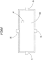
- FIG. 1 a block schematic diagram of an electronic fence system in accordance with an embodiment of the present invention is shown.
- the illustrated electronic fence system comprises a plurality of signal transmitters 10, a signal receiver 301 and a processor 302.
- the signal receiver 301 is set up on the vehicle, and the signal receiver 301 can be configured to receive transmission signals from each of the plurality of signal transmitters; in addition, the processor 302 can be connected to the signal receiver 301 and determine whether the vehicle is in the fence area 100 based on the transmission signal strength from each of the signal transmitters 10 received by the signal receiver 301.
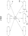
- each of the plurality of signal transmitters 10 is disposed in the form of the road stud or a ground lamp around the fence area 100, and such signal transmitters 10, 20 can be components that simply transmit signals or that can transmit and receive signals.
- the road stud is used as a component that simply transmits signals
- the ground lamp is used as an element capable of transmitting and receiving signals; however, the ground lamp can also be used as a component that simply transmits signals, or the road stud is used as an element capable of transmitting and receiving signals.
- signal transmitters 10 may be installed respectively around the fence area 100.
- road studs such as Bluetooth road studs
- a signal transmitter 10 (a road stud, such as a Bluetooth road stud) is taken as an example, and a directional antenna 101 can be set up in the signal transmitter 10 thereby transmitting positioning signals into the fence area 100.
- the specification of the installed directional antenna may be a grounded antenna that transmits and receives in a range of at least 10 meters, a field type of 180 degrees, and of a relatively small volume.
- the vehicle can be a shared vehicle.
- the shared vehicle can be, e.g., an electric or non-electric bicycle, a locomotive, a wheelchair, a scooter, or the like.
- the present invention will be described by taking only a shared bicycle as an example, but is not limited thereto.
- the shared bicycle is installed with an electronic vehicle identification, and the signal receiver 301 and the processor 302 are both integrated in the electronic vehicle identification, such that, when the intensity of each transmitted signal received by the electronic vehicle identification exceeds a preset threshold, it is determined that the shared bicycle is in the fence area 100 and the shared bicycle is allowed to be locked and returned.
- four signal transmitters 10 (road studs, such as Bluetooth road studs) with directional antennas all transmit positioning signals to the electronic vehicle identification 30 located in the fence area 100.
- the electronic vehicle identification 30 can receive the broadcast signals coming from the four signal transmitters 10, and all of the RSSI thereof exceed the preset threshold so as to allow the vehicle to be returned. Then, the electronic vehicle identification 30 can transmit the packet information of the parked bicycle to the Bluetooth bicycle lock of the shared bicycle, and the rider may lock and return the shared bicycle.
- the Bluetooth bicycle lock can also send the locking-success-information to the electronic vehicle identification such that the electronic vehicle identification can know the bicycle-return-success-information.
- the electronic vehicle identification further can wirelessly communicate with a mobile device so that, after the shared bicycle has been successfully locked and returned, it can send a bicycle-return-success-information to the mobile device.
- the mobile device can further wirelessly communicate with a cloud server so as to send a shared bicycle information indicating a successful bicycle return to the cloud server, in which the shared bicycle information indicating a successful bicycle return includes the positioning information of the shared bicycle.
- the electronic vehicle identification sends a bicycle-return-success-information to the mobile device, such as the user's mobile phone, to inform that it has been locked, indicating that the shared bicycle has been parked in the fence area of the electronic fence system, and the mobile phone can transmit the shared bicycle information to the cloud server in order to complete shared bicycle return process and to provide the positioning information of the returned bicycle to the cloud server.
- the mobile device such as the user's mobile phone
- the electronic vehicle identification if the electronic vehicle identification is outside the fence area, the electronic vehicle identification can be determined to be at least unable to receive the broadcast signal from one of the road studs, or among the received broadcast signals, at least one signal has a small RSSI. In this case, the electronic vehicle identification will not send the packet information of the bicycle-parking-success to the Bluetooth bicycle lock, nor can it send the bicycle-return-success-information to the mobile phone, so that the bicycle-returning process on the cloud side cannot be completed.
- the electronic vehicle identification can be combined with the Bluetooth bicycle lock to share the Bluetooth module, the battery, etc., so as to reduce the cost and avoid the wireless transmissions between the two.
- one of the plurality of signal transmitters 10 can be configured in the form of signal transmitter 20 (i.e., a ground lamp), and the signal transmitter 20 (ground lamp) can wirelessly communicate with the electronic vehicle identification 30 in order to receive the bicycle-return-success-information sent by the electronic vehicle identification 30, and then, by means of the wireless communication with the cloud server, a shared bicycle information indicating a successful bicycle return can be transmitted to the cloud server, wherein the shared bicycle information indicating a successful bicycle return includes the positioning information of the shared bicycle.
- signal transmitter 20 i.e., a ground lamp
- three signal transmitters 10 may be respectively installed around the fence area 100, and one of such signal transmitters 20 may be provided in the form of a ground lamp.
- the signal transmitter 20 (ground lamp, e.g., a Bluetooth ground lamp) can receive the bicycle return information from the electronic vehicle identification 30, and then the signal transmitter 20 (ground lamp) can transmit the shared bicycle information indicating success bicycle return to a cloud server.
- the signal transmitter 20 (ground lamp) can adopt the dual Bluetooth communication mode, and applies the Internet of Things 3G/4G/5G or WIFI or Low Power Wide Area Network (LPWAN), such as LORA or NBIOT, in order to communicate with the cloud server.
- LPWAN Low Power Wide Area Network
- three signal transmitters 10 e.g., road studs, such as Bluetooth road studs
- a signal transmitter 20 e.g., a ground lamp, such as a Bluetooth ground lamp
- a preset threshold if the intensity of each transmitted signal received by the electronic vehicle identification exceeds a preset threshold, it is determined that the shared bicycle is in the fence area and the shared bicycle is allowed to be locked and returned.
- the electronic vehicle identification 30 is outside the fence area 100, it can be determined that the electronic vehicle identification 30 cannot receive at least one broadcast signal coming from one of the directional antennas 101; for example, the electronic vehicle identification 30 may be located on the right side outside the fence area, and the broadcast signals coming from the directional antenna of the signal transmitter 10 (a road stud, such as a Bluetooth road stud) cannot be obtained, or its RSSI will be below a preset threshold.
- the electronic vehicle identification 30 will not send the packet information of the bicycle-parking-success to the Bluetooth bicycle lock, nor can it send the bicycle-return-success-information to the mobile phone, so that the bicycle-returning process on the cloud side cannot be completed. Therefore, the user needs to park the shared bicycle in the fence area to return the vehicle.
- the above-said ground lamp can further record the number of shared bicycles that have been parked in the fence area, and in case that the number of shared bicycles that have been parked in the fence area reaches a preset maximum parking number, it is possible, through the electronic vehicle identification, to prohibit the shared bicycle from being locked and returned in the fence area.
- the electronic vehicle identification is required to inform the ground lamp that the ground lamp needs to operate for recording such that the ground lamp can know the number of shared bicycles that have been parked in the fence area, thereby determining whether the maximum number of parking has been exceeded.
- the cloud server may be notified by the cloud server whether the maximum number of parkings has been exceeded, and then the mobile phone is informed whether it is allowed to park the borrowed bicycle. Or else, before the bicycle can be parked, the cloud server can inform the fence area of the electronic fence system that it is not allowed to park into the shared bicycle, and it is necessary to find another adjacent electronic fence system or wait for someone to borrow a bicycle in order to create an available space for parking.
- the information of the bicycle parking can be transmitted to the Bluetooth lock of the shared bicycle, and the user can lock the shared bicycle, and finally the Bluetooth lock can also send the lock-success-information to the electronic vehicle identification so the electronic vehicle identification to receive the bicycle-return-success-information.
- the electronic vehicle identification sends the bicycle-return-success-information to the ground lamp, and the ground lamp transmits the information to the cloud server, thereby completing the bicycle return process and providing the positioning information of the returned bicycle location to the cloud server.
- the electronic vehicle identification sends the bicycle-return-success-information to the mobile phone, and the mobile phone transmits the information to the cloud server, thereby completing the bicycle return process and providing the positioning information of the returned bicycle location to the cloud server.
- the processor can determine whether the vehicle is in the fence area based on the signal strength of each signal transmitter received by the receiver. Therefore, not only the recognition accuracy can be enhanced, but also the installation operations can be simple, the maintenance processes can be easy, and the costs can be reduced, thus offering great convenience to the user for returning the borrowed vehicle.
- an embodiment of the present invention also provides an electronic fence system comprising the aforementioned electronic fence system and the vehicle.
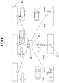
- a plurality of electronic fence systems may be provided for places where stations, docks, school gates, markets, parks, and the like are required to share a high amount of bicycles.
- a complete set of broadcast messages of the road studs provided by the fence area 1001 and the fence area 1002 can be simultaneously received.
- the shared bicycle 51 as long as there is a complete road stud RSSI, it can be sent to the corresponding ground lamp to calculate, and then so long as one of the ground lamps responds in the fence area to which it belongs, the return process is allowed to operate.
- the shared bicycle 51 is unable to obtain the return permit offered by the fence area 1001 or the fence area 1002.
- the shared bicycle 52 can obtain the return permission given by the fence area 1001, but the return permission granted by the fence area 1002 cannot be obtained
- the shared bicycle 53 can obtain the return permission given by the fence area 1002, but the return permission granted by the fence area 1001 cannot be obtained.
- the units of the electronic fence system can be expanded laterally, as small as one unit, e.g., an area of 10m ⁇ 2m, and then several units may be connected in series.
- the fence area of the electronic fence system has an area of 10m (Length) ⁇ 2m (Width) as a unit, and 4-6 Bluetooth road studs are installed at the boundary of the fence area, one of which has a function of a router such as a road stud, thereby communicating with the electronic vehicle identification on the shared bicycle and also communicating with the cloud server via LORA or NBIOT or WIFI, or otherwise 3G/4G/5G telecommunications in order to implement cloud payment or reservation services.
- the electronic fence system can accurately determine whether the vehicle is located in the fence area, thereby enabling high recognition accuracy, simple installation operations, easy maintenance tasks, and effectively reduced costs. In this way, it is possible to provide great convenience to users for returning the borrowed vehicle.
- An embodiment according to another feature of the present invention further provides an electronic fence system, comprising a plurality of signal transmitters and a signal receiver, wherein the plurality of signal transmitters are disposed on the ground to define a fence area having a boundary, and one of the plurality of signal transmitters is configured in the form of a ground lamp which stores a hyperplane model for determining the inside and the outside of the fence area; in addition, the signal receiver is set up on a vehicle and configured to receive the transmission signals coming from each of the plurality of signal transmitters, and sends the signals of each signal transmitter to the electronic vehicle identification on the vehicle, the electronic vehicle identification can wirelessly communication with the ground lamp to transmit the transmission signals of each signal transmitter to the ground lamp, and the ground lamp determines whether the vehicle is within the fence area according to the received signals of signal transmitters and the hyperplane model.
- the rest signal transmitters of the plurality of signal transmitters are configured in the form of a road stud and installed around the fence area along with the ground lamp.
- the number of such a plurality of signal transmitters 10 may be four, and three of the four signal transmitters are provided in the form of road studs such as Bluetooth road studs, and the remained one is provided in the form of a ground lamp.
- the electronic vehicle identification receives the transmission signals of the four signal transmitters RSSI-1, RSSI-2, RSSI-3 and RSSI-4, and transmits to the ground lamp which determines, based on the hyperplane model stored in its memory, whether the shared bicycle is located inside the fence area or outside the fence area;
- the applied determination method may be SVM (Support Vector Machine) algorithm, or other classifier algorithms, such as linear classifiers (Fisher's linear discriminant, Logistic Regression, Naive Bayes classifier, Perceptron); Support Vector Machines (Least squares support vector machines); Quadratic classifiers; Kernel estimation (k-nearest neighbor); Boosting (meta-algorithm); Decision trees (Random forests); Learning vector quantization; Neural Networks; Deep Learning ... etc.
- SVM Serial Vector Machine
- classifier algorithms such as linear classifiers (Fisher's linear discriminant, Logistic Regression, Naive Bayes classifier, Perceptron); Support Vector Machines (Least squares support
- the decision function is as follows:
- the core function ⁇ i is the Lagrange Multiplier
- y i a classification made by using a hyperplane and indicating inside or outside the fence area
- b is a constant.
- the decision function of the SVM algorithm is represented by a matrix besides, although the above-mentioned decision function uses 200 training data items as an example, it is possible to adjust the number in practice based on classification accuracy, computation load, memory capacity, or the like.
- the in-field actual corrections can be performed based on the road studs and the ground lamps installed around the fence areas. For example, ten shared bicycles may be parked inside the fence area, and at least two shared bicycles may be randomly placed outside the fence area; for example, two bicycles are placed outside and "above” (as shown in the Figure) the fence area, two bicycles are placed outside and "under” the fence area, three bicycles are placed outside and on right side of the fence area, and three bicycles are placed outside and on left side of the fence area.
- the RSSI-1, RSSI-2, RSSI-3, RSSI-4 received by each bicycle's electronic vehicle identification are transmitted to the ground lamp, received by the ground lamp, thereby establishing the four-dimensional space of the RSSI-1, RSSI-2, RSSI-3 and RSSI-4; then, based on the SVM algorithm, training the hyperplane model for determining the outside and inside of the fence area.
- the acquired hyperplane model is stored in the ground lamp so as to complete the construction of the electronic fence system.
- test data set includes the following materials:
- the data for the ten bicycles parked in the fence area may include B1 (R1, R2, R3, R4), B2 (R1, R2, R3, R4), B3 (R1, R2, R3, R4), B4 (R1, R2), R3, R4), B5 (R1, R2, R3, R4), B6 (R1, R2, R3, R4), B7 (R1, R2, R3, R4), B8 (R1, R2, R3, R4), B9 (R1, R2, R3, R4) and B10 (R1, R2, R3, R4);
- Data for the two bicycles parked "above” and outside the fence area include BU1 (R1, R2, R3, R4) and BU2 (R1, R2, R3, R4);
- Data for the two bicycles parked "under” and outside the fence area include BD3 (R1, R2, R3, R4) and BD4 (R1, R2, R3, R4);
- Data for the three bicycles parked on the right side of and outside the fence area include BR5 (R1, R2, R3, R4), BR6 (R1, R2, R3, R4), BR7 (R1, R2, R3, R4); and
- Data for the three bicycles parked on the left side of and outside the fence area include BL8 (R1, R2, R3, R4), BL9 (R1, R2, R3, R4) and BL10 (R1, R2, R3, R4).
- the signal receiver can be integrated in the electronic vehicle identification, and the electronic vehicle identification is further installed with an accelerometer, such that the electronic vehicle identification is monitored by the accelerometer to turn on the signal receiver when the vehicle stops its movement in order to scan the signals coming from each road stud and ground lamp, and then the scanned signals can be broadcasted to the ground lamp.
- the electronic vehicle identification includes an accelerometer
- the accelerometer detects that the speed of the shared bicycle is zero, and the electronic vehicle identification can turn on the signal receiver, e.g., the Bluetooth receiving function, and start to scan RSSI-1, RSSI-2, RSSI-3, RSSI-4, and then broadcast to the ground lamp.
- the ground lamp determines whether the bicycle is currently outside the fence area or inside the fence area according to the hyperplane model about the inside of the fence area and the outside of the fence area, and then informs the electronic vehicle identification to allow the return of the shared bicycle.
- the ground lamp can operate in the dual mode, the three road studs all work in the broadcast mode, while the electronic vehicle identification works in the Master mode.
- the remained three road studs can be also designed as ground lamps in order to become scanners, and the three ground lamps can be of oriented Bluetooth dual-mode (not dual Bluetooth); in addition, and the ground lamp that interacts with the electronic vehicle identification needs to apply dual Bluetooth and LORA/NBIOT communication methods.
- the signal transmitter 20 (a ground lamp, e.g., a Bluetooth ground lamp) is further provided with a battery 201 and a charging control circuit 202, in which the charging control circuit 202 converts solar energy into electrical energy by means of a solar panel 203 so as to charge the battery 201.
- a ground lamp e.g., a Bluetooth ground lamp
- the battery 201 can supply electric power respectively to the main Bluetooth module 204, the slave Bluetooth module 205 and the LORA module 206, in which the main Bluetooth module 204, the slave Bluetooth module 205 and the LORA module 206 mutually communicate by means of a UART (Universal Asynchronous Receiver/Transmitter) method.
- UART Universal Asynchronous Receiver/Transmitter
- the battery 201 can supply power respectively to the main Bluetooth module 204 and the slave Bluetooth module 205, and the main Bluetooth module 204 and the slave Bluetooth module 205 mutually communicate via the UART method.
- the ground lamp when the signal transmitter is arranged in the form of a ground lamp, the ground lamp is to be installed under the ground, which can reduce the interference of secondary reflection and enhance the stability of the RSSI.
- the electronic vehicle identification can be configured to use a single broadcast channel, so as to make the broadcast channel of each electronic vehicle identification interlaced as much as possible, thereby that the ground lamp can quickly receive the broadcast from each electronic vehicle identification multiple times; additionally, because the individual electronic vehicle identification has a fixed channel frequency and a fixed wavelength, the broadcast packet of the same electronic vehicle identification received multiple times can exhibit a stable RSSI.
- each ground lamp can be installed with a directional antenna and an omnidirectional antenna; that is, a directional antenna can be installed in each ground lamp.
- a directional antenna can be installed in each ground lamp.
- the A ground lamp is attached with a directional antenna toward the fence area; similarly, the directional antenna attached to the B ground lamp is also towards the inside of the fence area.
- the omnidirectional antenna of the ground lamp A will get a very strong RSSI, but the installed directional antenna should achieve a very low RSSI, because the electronic vehicle identification is located on the rear side of the directional antenna, while the B ground lamp can read the electronic vehicle identification, but at a great distance. In this way, the electronic vehicle identification outside the fence area can be accurately identified, which greatly reduces the misjudgment.
- the directional antenna needs to be properly designed so as to reduce false positives by adjusting the field type and gain thereof.
- the omnidirectional antenna installed in the ground lamp covers a communication connection range of more than ten meters
- the directional antenna set up in the ground lamp covers a range of about six meters
- the gain in the zero direction is the highest, up to six meters, deviated from the zero direction, and its gain is symmetrically reduced.
- the directional antenna may not detect, but the omnidirectional antenna still can.
- the RSSI is still five meters away from the omnidirectional antenna of the electronic vehicle identification, and there is still +/-1 meter error, so the calculation may misjudge the electronic vehicle identification locating outside the fence area in a possibility of 50%.
- the directional antenna in the A ground lamp or the B ground lamp detects the electronic vehicle identification, it can be confirmed that the electronic vehicle identification is in the fence area, and in case neither the directional antenna of the A ground lamp nor the directional antenna of the B ground lamp detects it, then the possibility of the electronic vehicle identification locating within the fence area can be excluded.
- the A and B ground lamps can be respectively installed in the middle locations on the left and right sides of the electronic fence system, and these two ground lamps installed on the two sides of the omnidirectional antenna can communicate the detected electronic vehicle identification data with each other, so that the possible location of the electronic vehicle identification can be derived via comprehensive calculations, and then narrowing the range and eliminating impossible positions through the directional antenna, thereby improving the recognition accuracy of the electronic fence system.
- this additional plurality of directional antennas can also compare their RSSI with the RSSI of the omnidirectional antenna, thus conjunctively making decisions and greatly reducing wrong determination results.
- An electronic fence system defines a fence area having a boundary by providing a plurality of signal transmitters on the ground, and one of the plurality of signal transmitters is configured in the form of a ground lamp which stores a hyperplane model for determining the inside and the outside of the fence area; in addition, the signal receiver is set up on a vehicle and configured to receive the transmission signals coming from each of the plurality of signal transmitters, and sends the signals of each signal transmitter to the electronic vehicle identification on the vehicle, the electronic vehicle identification can wirelessly communication with the ground lamp to transmit the transmission signals of each signal transmitter to the ground lamp, and the ground lamp determines whether the vehicle is within the fence area according to the received signals of signal transmitters and the hyperplane model. Therefore, the recognition accuracy can be improved, the installation is simple, easy to maintain, and the costs can be greatly reduced, which brings great convenience to the user for returning the borrowed vehicle.
- an electronic fence system alarm system as shown in Figure 8 , wherein the electronic fence system alarm system comprises the above-described signal transmitter 20 and the vehicle 3.
- the vehicle 3 is provided with an electronic vehicle identification 30 and an alarm component 31, and the electronic vehicle identification 30 is connected to the alarm component 31, wherein, after the vehicle 3 has been parked in the fence area, the signal transmitter 20 (a ground lamp, for example, a Bluetooth ground lamp) is kept in a connection state with the electronic vehicle identification 30, and an alarm prompt can be issued by the electronic vehicle identification 30 controlling the alarm component 31 when it is judged that the vehicle 3 is illegally dragged away from the fence area.
- the signal transmitter 20 a ground lamp, for example, a Bluetooth ground lamp
- an accelerometer can be installed in the electronic vehicle identification 30, and the electronic vehicle identification 30 can detect that the vehicle 3 is moved by means of the accelerometer when the vehicle is not unlocked, and can inform the ground lamp that the vehicle 3 has been illegally moved by wirelessly communicating with the ground lamp, such that the ground lamp can correctly determine whether the vehicle 3 is illegally dragged out of the fence area.
- the electronic vehicle identification can read the value of the accelerometer every 0.5 seconds in order to determine whether the change exceeds a range, or the value exceeds the prescribed value, and the calculation method may be, e.g., the sum of three-axis absolute values, or the square root of the sum of squares, and in case it exceeds the predetermined threshold, the Bluetooth broadcast function will be activated to establish communications with the ground lamp, which is mainly for saving power consumption. So the electronic vehicle identification can apply an accelerometer to detect whether the vehicle, such as a shared bicycle, is moved.
- the electronic vehicle identification on the shared bicycle parked in the fence area is continuously connected with the ground lamp, and once the bicycle is illegally dragged off the fence area, indicating the connection is not maintained, but becoming offline, the ground lamp will control the alarm component installed on the bicycle via the electronic vehicle identification thereby automatically activating the alarm component, e.g., a buzzer, to issue an alarming sound.
- the alarm component e.g., a buzzer
- the accelerometer on the shared bicycle is used to detect whether the bicycle is moved after the bicycle has been parked.
- the electronic vehicle identification will be notified to trigger the Bluetooth license plate to establish a connection with the ground lamp in order to notify the ground lamp that the bicycle of this electronic vehicle identification has been illegally moved.
- the buzzer on the bicycle will automatically sound a beep as long as it leaves the connection range.
- the electronic vehicle identification after the vehicle is parked in the fence area, the electronic vehicle identification broadcasts the scanned transmission signal to the ground lamp every first preset time period; and when the vehicle is borrowed from the fence area and operates in the running status, the electronic vehicle identification broadcasts the scanned transmission signal to the ground lamp installed on the roadside every second preset time period.
- the second preset time period may be greater than the first preset time period, for example, the second preset time period may be 10 seconds.
- the ground lamp can record the location information of the borrowed vehicle according to the received transmission signal, and wirelessly communicate with the cloud server to send the location information of the borrowed vehicle to the cloud server so that the cloud server can track the borrowed vehicle.
- the electronic vehicle identification may be scanned at regular intervals during riding.
- the transmitted signal can be broadcasted to the ground lamp 61 of the roadside gateway 6 such that the ground lamp can upload the location of the borrowed bicycle to the cloud which can record the whereabouts of the borrowed bicycle.
- position tracking process can be performed when the bicycle slows down (the accelerometer can detect this) and approaches an electronic fence system.
- the electronic vehicle identification further monitors its own power and extends the first preset time period or the second preset time period to reduce the broadcast frequency when the power is lower than a preset value.
- the power can be measured every hour, and if the power is lower than a first preset power, the fixed duration of the first preset time period or the second preset time period be doubled; If the power is lower than a second preset power, the fixed duration of the first preset time period or the second preset time period can be extended by four times, wherein the second preset power is smaller than the first preset power.
- the electronic vehicle identification can also send a broadcast signal to the mobile phone or the ground lamp, thereby notifying the current state of the power and requesting appropriate processes.
- the electronic vehicle identification and the alarm component are installed on the vehicle, when the vehicle is parked in the fence area, the ground lamps of the electronic fence system can be kept in a connection state with the electronic vehicle identification, and in case it is determined that the vehicle has been illegally dragged away from the fence area, the alarm component can be controlled by the electronic vehicle identification to order to issue an alarm prompt, such that it is possible to enable effective monitoring of the vehicle parked in the electronic fence system so as to prevent theft events, thus offering greatly improved security.
- the Bluetooth road stud can broadcast 5 times or 2 times per second, which can be determined according to the actual time period, such as busy commute time (5 times per second), non-working time (2 times per second), in which the communication protocol of the road stud can be shown in Table 1 below.
- the broadcast data packet of the road stud provided in the form of a ground lamp can be described as Table 2 below.
- Table 2 - Road stud (included in the ground lamp) Broadcast Data Packet byte[0-5] Road stud (Included in Ground lamp) Broadcase Data byte[2-20] Mode Person Time Place Object Master (6 bytes) (6 bytes) (1 byte) (6 bytes) (3 bytes) ID Code: $% MAC address Second Longitude: x 1 x 2 x 3 x 4 x 5 x 6 x 3 x 4 y 3 y 4 -4 MAC address btag Latitude: y 1 y 2 y 3 y 4 y 5 y 6 (Ground lamp) Binary btag Identifier 4 bytes HEX BCD Longitude and Latitude: x 3 x 4 y 3 y 4 First two codes of ground lamp's longitude and latitude -4 Under (Ground lamp) HEX BCD Road stud Installation Location
- the shared bicycle scans at a regular interval (scanning for 1 second per 5 seconds) or does not scan. Or otherwise, the vehicle number can be broadcasted so the roadside ground lamp can receive it, thus confirming the bicycle has been borrowed in order to follow the shared bicycle.
- each road stud of each electronic fence system must collect at least 5 data, having them averaged and rounded up, and then sending them to the mater Bluetooth module in the ground lamp.
- the electronic vehicle identification can know the MAC address of the master Bluetooth module in the ground lamp from the aforementioned Table 2.
- the communication protocol of the connection is shown in Table 3 below.
- Table 3 Data Packet of Electronic vehicle identification Connecting Ground lamp byte[0-5] Electronic vehicle identification Connection Information byte[2-19] Mode Person Time Object (6 bytes) (6 bytes) (1 byte) (4 bytes) ID Code: MAC address Second RSSI -1 $% RSSI -2 "rssi" RSSI -3 RSSI -4 Binary rssi Identifier 4 bytes HEX BCD Each RSSI needs one byte
- the data packet of the connected Bluetooth bicycle lock is as shown in Table 4 hereunder.
- Table 5 Data Packet of Electronic vehicle identification Connecting Ground lamp byte[0-5] Electronic vehicle identification Connection Information byte[2-19] Mode Person Time Place Object (6 bytes) (6 bytes) (1 byte) (6 bytes) (1 bytes) ID Code: $% safe MAC address Second Longitude: x 1 x 2 x 3 x 4 x 5 x 6 Illegal theft Latitude: y 1 y 2 y 3 y 4 y 5 y 6 Binary safe Identifier 4 bytes HEX BCD Longitude and Latitude: 1 Illegal theft 0 Safe BCD Ground lamp Installation Location
- the electronic vehicle identification after the electronic vehicle identification sends out the RSSIs collected from the four road studs to the ground lamp, it switches to the slave mode, and waits for the connection of the ground lamp to notify whether the bicycle can be returned; meanwhile, the ground lamp uses the SVM algorithm to determine whether the electronic vehicle identification is located at the inside of the fence area or the outside of the fence area, and uses the connection to inform the electronic vehicle identification of the information.
- the communication protocol is shown in Table 6 below.
- Table 6 Data Packet of Ground lamp Pushed to Electronic vehicle identification byte[0-5] Connection Data byte[2-19] Mode Person Time Place Object (6 bytes) (6 bytes) (1 byte) (6 bytes) (1 byte) ID code: $# inin MAC address Second Inside or outside fence area Binary inin Identifier 4 bytes HEX BCD Inside fence area value 1 Outside fence area value 0
- the ground lamp When the ground lamp uploads the data to the cloud, it mainly uses the NBIOT method to upload thereto, which should include: the report of safety and bicycle passing (sent out once after 10-seconds accumulation), the report of bicycle parking (sent out within 1 second), the report of bicycle lending (sent out within 1 second), and the report of bicycle theft (sent out within 1 second).
- the communication protocol thereof is shown in Tables 7 - 10 as below.
- Table 7 Data Packet of Ground lamp Uploading to Cloud (Bicycle Lending) byte[0-1] NBIOT byte[2-40] Mode (6 bytes) Person (6 bytes) Time (1 byte) Place (6 bytes) Borrow (6 bytes) Borrow (6 bytes) ID Code: $% rent MAC address Second Longitude: x 1 x 2 x 3 x 4 x 5 x 6 MAC address MAC address Latitude: y 1 y 2 y 3 y 4 y 5 y 6 Binary rent Identifier 4 bytes HEX BCD Longitude and latitude: BCD Ground lamp Installaton Location HEX HEX Table 8 - Data Packet of Ground lamp Uploading to Cloud (Bicycle Parking) byte[0-1] NBIOT byte[2-40] Mode (6 bytes) Person (6 bytes) Time (1 byte) Place (6 bytes) Return (6 bytes) Return (6 bytes) ID Code: $% retu MAC address Second Longtude: x 1 x 2 x 3 x 4
- the Bluetooth road stud can take the specifications of Table 11 shown below.
- Table 11 - Specification Table of Bluetooth Road stud Method of Use Mounted on the ground Bluetooth Module Bluetooth 4.2/5.0, connection distance of at least 20m Bluetooth Antenna Highly directional antenna OAD YES Input Voltage 4.5V, convertible to 3.3V DC to provide power to Bluetooth module Output Signal -- Size (including housing) Diameter 100 mm x 80 mm Weight 100g Solar Panel 12 cm x 12 cm Battery Capacity 5000 mAh (optional)
- the ground lamp can adopt the specification shown in Table 12 as below.
- Table 12 Specification Table of Ground lamp Method of Use Mounted on the ground Bluetooth Module Bluetooth 4.2/5.0, connection distance of at least 20m Bluetooth Antenna Highly directional antenna LORA or NBIOT Power 1 W, communication distance of at least 1 kilometer OAD YES Input Voltage 4.5V, convertible to 3.3V DC to provide power to Bluetooth module Output Signal -- Size (including housing) Diameter 200 mm x 80 mm Weight 100g I/O Scalability UART and 4 I/P pins for optional external sensors Solar Panel 12 cm x 12 cm Battery Capacity 5000 mAh (optional) Built-in Positioning SDK YES PetaCom MESH YES, requiring conjunctive bwRouter and cloud
- the electronic vehicle identification can apply the specification shown in Table 13 as below.
- the electronic fence system of the embodiments according to the present invention can define a fence area having a boundary by means of installing a plurality of signal transmitters on the ground, such that it is possible to determine whether a vehicle, e.g., a shared bicycle, is located in the fence area by using RSSI information, which not only enables high recognition accuracy, but also is simple to install and easy to maintain, and allows reduced costs.
- a vehicle e.g., a shared bicycle
- the embodiments of the present invention can be provided as methods, systems, or computer program products. Accordingly, the present invention may take the form of a fully hardware embodiment, a fully software embodiment, or an embodiment combining both soft and hardware features. Moreover, the present invention may adopt the form of one or more computer program products implemented on the computer usable storage media (including, but not limited to, disk memory, CD-ROM, optical memory, etc.) containing computer executable program codes.
- the computer usable storage media including, but not limited to, disk memory, CD-ROM, optical memory, etc.
- Such computer program instructions can be provided to a processor of a general purpose computer, a special purpose computer, an embedded processor or other programmable data processing device in order to produce a machine so that, through the instructions executed by the processor in a computer or other programmable data processing device, it is possible to generate a device capable of implementing the functions specified in one or more processes of the flowcharts and/or one or more blocks of the block diagrams as previously described.
- these computer program instructions can be stored in a computer readable memory which can boot a computer or other programmable data processing device in order to operate in a particular approach, such that the instructions stored in the computer readable memory can generate a manufacture product having the instruction means capable of implementing the functions specified in one or more processes of the flowcharts and/or one or more blocks of the block diagrams as previously described.
- these computer program instructions can be also loaded onto a computer or other programmable data processing device so as to perform a series of operational steps on a computer or other programmable device to produce computer-implemented processes on a computer or other programmable device.
- instructions executed on a computer or other programmable device provide steps for implementing the functions specified in one or more processes of the flowcharts and/or one or more blocks of the block diagrams as previously described.
- any reference signs placed between parentheses should not be construed as limitations.
- the word “comprising” does not exclude the presence of the components or steps that are not listed in the Claims.
- the word “a” or “an” preceding a component does not exclude the presence of a plurality of such components.
- the present invention can be effectively embodied by means of a hardware comprising a number of different components and by means of an appropriately programmed computer. In the Claims where several means are enumerated, some or all of these means can be embodied by the same hardware item.
- the use of the words “first”, “second”, and “third”, etc. does not denote any order. These words can be interpreted as names.
- first and second are used merely for descriptive purposes and are not to be considered as concerning the quantity of the indicated or implied relative importance or implicitly indicated technical features.
- the features defining “first” and “second” may either explicitly or implicitly include one or more of the features.
- the meaning of “plurality” is two or more in the descriptions of the present invention.
- a first feature is “on” or “below” a second feature may indicate the direct contact of the first and second features, or the first and second features may be in indirect contact by way of an intermediary media.
- a first feature is “above”, “on” and “over” a second feature may be that the first feature is directly above or slantingly above the second feature, or merely indicates that the level of the first feature is higher than the one of the second feature.
- a first feature is “below”, “under” and “beneath” a second feature may be that the first feature is directly under or slantingly under the second feature, or merely indicates that the level of the first feature is lower than the one of the second feature.
Landscapes
- Engineering & Computer Science (AREA)
- Computer Networks & Wireless Communication (AREA)
- Signal Processing (AREA)
- Physics & Mathematics (AREA)
- General Physics & Mathematics (AREA)
- Quality & Reliability (AREA)
- Electromagnetism (AREA)
- Train Traffic Observation, Control, And Security (AREA)
- Traffic Control Systems (AREA)
Applications Claiming Priority (1)
| Application Number | Priority Date | Filing Date | Title |
|---|---|---|---|
| TW107142257A TW202020473A (zh) | 2018-11-27 | 2018-11-27 | 電子圍欄以及電子圍欄系統 |
Publications (1)
| Publication Number | Publication Date |
|---|---|
| EP3661236A1 true EP3661236A1 (de) | 2020-06-03 |
Family
ID=66074803
Family Applications (1)
| Application Number | Title | Priority Date | Filing Date |
|---|---|---|---|
| EP19211150.8A Withdrawn EP3661236A1 (de) | 2018-11-27 | 2019-11-25 | Elektronischer zaun und elektronisches zaunsystem |
Country Status (4)
| Country | Link |
|---|---|
| US (1) | US20200168101A1 (de) |
| EP (1) | EP3661236A1 (de) |
| CN (4) | CN109637116A (de) |
| TW (1) | TW202020473A (de) |
Families Citing this family (42)
| Publication number | Priority date | Publication date | Assignee | Title |
|---|---|---|---|---|
| TW202020473A (zh) * | 2018-11-27 | 2020-06-01 | 奇異平台股份有限公司 | 電子圍欄以及電子圍欄系統 |
| CN110058563B (zh) * | 2019-01-18 | 2020-05-05 | 丰疆智能科技研究院(常州)有限公司 | 作业监控系统及其监控方法 |
| CN110398240B (zh) * | 2019-06-12 | 2021-07-20 | 北京邮电大学 | 一种基于电子围栏的位置判定方法、装置与电子设备 |
| CN111833486A (zh) * | 2019-08-23 | 2020-10-27 | 北京骑胜科技有限公司 | 控制共享单车停车位置的方法和装置 |
| CN110675636A (zh) * | 2019-10-09 | 2020-01-10 | 上海图丽信息技术有限公司 | 一种电子车牌闯禁令应用系统 |
| CN110761701B (zh) * | 2019-10-18 | 2020-10-30 | 中大永新信息科技有限公司 | 一种带有报警功能的电子围栏防护装置 |
| CN110809237A (zh) * | 2019-11-06 | 2020-02-18 | 山东高速信联科技有限公司 | 一种基于5.8ghz频段的电子围栏以及搭建方法 |
| CN111861829B (zh) * | 2019-12-31 | 2024-10-15 | 北京骑胜科技有限公司 | 基于共享设备的提示方法、装置、电子设备及存储介质 |
| WO2021136147A1 (zh) * | 2019-12-31 | 2021-07-08 | 北京骑胜科技有限公司 | 一种共享设备的预设区域定位方法和系统 |
| CN111260914B (zh) * | 2020-01-17 | 2021-07-06 | 上海钧正网络科技有限公司 | 车辆动态电子围栏的形成方法和车辆停靠方法 |
| CN111461500B (zh) * | 2020-03-12 | 2022-04-05 | 北京航空航天大学 | 一种基于动态电子围栏和强化学习的共享单车系统潮汐现象控制方法 |
| US10783784B1 (en) * | 2020-03-31 | 2020-09-22 | Lyft, Inc. | Free lock detection of a micromobility transit vehicle systems and methods |
| CN111862581A (zh) * | 2020-06-22 | 2020-10-30 | 上海钧正网络科技有限公司 | 车辆锁控制方法、装置、车辆停车系统和存储介质 |
| CN111915886B (zh) * | 2020-07-02 | 2022-07-08 | 杭州金通科技集团股份有限公司 | 一种通过车扫地桩统计站点车辆的系统及方法 |
| CN111951541A (zh) * | 2020-07-14 | 2020-11-17 | 上海明略人工智能(集团)有限公司 | 一种共享交通工具的停放控制方法、存储介质和设备 |
| CN111988738A (zh) * | 2020-07-31 | 2020-11-24 | 北京骑胜科技有限公司 | 交通工具控制方法、装置、交通工具和存储介质 |
| CN112073898A (zh) * | 2020-08-10 | 2020-12-11 | 杭州金通科技集团股份有限公司 | 一种基于改进蓝牙天线的定位地桩 |
| TWI748718B (zh) * | 2020-10-30 | 2021-12-01 | 拓連科技股份有限公司 | 移動式電動車充電裝置之管理系統及其管理方法 |
| CN112270825B (zh) * | 2020-11-03 | 2022-08-02 | 宁波小遛共享信息科技有限公司 | 一种停车判定方法、装置、电子设备及存储介质 |
| CN112637766A (zh) * | 2020-12-23 | 2021-04-09 | 浙江泺平信息技术有限公司 | 一种共享电单车的还车方法和系统 |
| CN112820030B (zh) * | 2020-12-26 | 2023-02-17 | 北京骑胜科技有限公司 | 交通工具归还方法、装置、计算机设备和存储介质 |
| CN113207083B (zh) * | 2021-04-16 | 2023-04-07 | 南京大鱼半导体有限公司 | 检测终端位置的方法、装置、存储介质及终端 |
| CN113271545B (zh) * | 2021-05-20 | 2022-11-15 | 北京智慧图科技有限责任公司 | 一种基于蓝牙信标的解决共享单车乱停放的方法及系统 |
| CN114928809B (zh) * | 2021-06-11 | 2023-04-07 | 荣耀终端有限公司 | 一种地理围栏的使用方法及电子设备 |
| CN217100315U (zh) * | 2021-06-17 | 2022-08-02 | 刘军 | 一种折叠共享车辆 |
| CN113507688A (zh) * | 2021-07-21 | 2021-10-15 | 广西盖德科技有限公司 | 定位数据与地理围栏构建的动态虚拟停车场方法及系统 |
| CN113453154A (zh) * | 2021-07-26 | 2021-09-28 | 刘养明 | 关于共享单车停放管理的相关技术 |
| CN113593131B (zh) * | 2021-07-28 | 2025-02-11 | 厦门市思芯微科技有限公司 | 一种共享蓝牙耳机管理装置以及租借和归还方法 |
| CN113867244A (zh) * | 2021-08-27 | 2021-12-31 | 山东大学 | 一种基于北斗的电子围栏非道路车辆监控平台系统及其工作方法 |
| CN113794990B (zh) * | 2021-09-24 | 2024-06-25 | 深圳市泰比特科技有限公司 | 一种基于电子围栏的共享单车控制方法及系统 |
| CN116206434A (zh) * | 2021-11-30 | 2023-06-02 | 北京骑胜科技有限公司 | 停车控制方法、设备、系统、存储介质和程序产品 |
| CN114666772A (zh) * | 2022-02-07 | 2022-06-24 | 摩拜(北京)信息技术有限公司 | 车辆定位方法、装置及服务器 |
| CN114567854B (zh) * | 2022-02-25 | 2023-01-24 | 北京骑胜科技有限公司 | 基于蓝牙的停车点车辆检测方法、装置、电子设备及介质 |
| CN114446075B (zh) * | 2022-04-07 | 2022-07-01 | 北京阿帕科蓝科技有限公司 | 一种召回车辆的方法 |
| CN114842581B (zh) * | 2022-05-14 | 2024-04-30 | 上海协同数字化科技创新研究院 | 基于蓝牙的城市共享单车落锁控制系统及管理控制方法 |
| CN114979202B (zh) * | 2022-05-20 | 2023-06-27 | 重庆长安汽车股份有限公司 | 一种基于电子围栏的停车主动解锁方法和系统 |
| CN117014811B (zh) * | 2022-12-27 | 2024-10-01 | 慧之安信息技术股份有限公司 | 基于视觉识别和无线控制的共享自行车管理方法 |
| CN116208912B (zh) * | 2022-12-30 | 2025-10-17 | 永安行科技股份有限公司 | 一种基于电子围栏的车辆定位方法及定位装置 |
| CN117275145A (zh) * | 2023-09-20 | 2023-12-22 | 中国银行股份有限公司 | 共享车辆的归还方法、装置、电子设备及计算机存储介质 |
| CN118605528A (zh) * | 2024-06-14 | 2024-09-06 | 武汉客车制造股份有限公司 | 一种基于超宽带定位的无人驾驶方法及装置 |
| CN118711313A (zh) * | 2024-08-30 | 2024-09-27 | 西安超嗨网络科技有限公司 | 基于定向天线电子围栏的智能购物车多层防盗方法及装置 |
| CN121352422A (zh) * | 2025-12-18 | 2026-01-16 | 北京工业大学 | 基于电子围栏的共享单车投放方法和装置 |
Citations (2)
| Publication number | Priority date | Publication date | Assignee | Title |
|---|---|---|---|---|
| US20150369618A1 (en) * | 2014-06-18 | 2015-12-24 | Chris Barnard | Interactive applications using data from light sensory networks |
| US20170101110A1 (en) * | 2015-10-08 | 2017-04-13 | Lg Electronics Inc. | Convenience Apparatus For Vehicle And Vehicle |
Family Cites Families (27)
| Publication number | Priority date | Publication date | Assignee | Title |
|---|---|---|---|---|
| US5917407A (en) * | 1997-05-15 | 1999-06-29 | Squire; Joshua H. M. | Unattended automated bicycle rental station |
| JP5245392B2 (ja) * | 2007-12-21 | 2013-07-24 | 株式会社Jvcケンウッド | 車載器、情報の出力方法および情報提供システム |
| CN102855764A (zh) * | 2011-06-30 | 2013-01-02 | 国际商业机器公司 | 交通信号广播系统、再现系统及广播方法、再现方法 |
| US9414193B2 (en) * | 2013-07-17 | 2016-08-09 | Qualcomm Incorporated | Communicating RF fingerprint-based geofences |
| US9194955B1 (en) * | 2014-01-16 | 2015-11-24 | WI-MM Corporation | Cloud based activity monitor for bicycles with fleet management and rider analytics system |
| DE102014212505A1 (de) * | 2014-06-27 | 2015-12-31 | Continental Automotive Gmbh | Diversifiziertes Antennensystem zur Fahrzeug-zu-Fahrzeug oder Fahrzeug-zu-Infrastruktur Kommunikation |
| US9380421B1 (en) * | 2014-11-07 | 2016-06-28 | Wells Fargo Bank, N.A. | Multi-channel geo-fencing systems and methods |
| JP6500517B2 (ja) * | 2015-03-10 | 2019-04-17 | 住友電気工業株式会社 | 路側通信装置、データ中継方法、中央装置、コンピュータプログラム、及びデータ処理方法 |
| KR101922055B1 (ko) * | 2016-08-31 | 2018-11-27 | 주식회사 바이시큐 | 자전거 잠금 장치 및 잠금 방법 |
| CN106851529A (zh) * | 2016-12-01 | 2017-06-13 | 致富电子科技有限公司 | 用于交通工具定位的信标系统及交通工具定位方法 |
| DE102017102116A1 (de) * | 2017-02-03 | 2018-08-09 | Jungheinrich Aktiengesellschaft | Verfahren und System zur Positionsbestimmung von mindestens einem Flurförderzeug |
| CN106971610B (zh) * | 2017-04-28 | 2018-03-23 | 北京摩拜科技有限公司 | 确定物体处于目标区域的方法、停车管理设备和系统 |
| US10562580B2 (en) * | 2017-04-29 | 2020-02-18 | HangZhou HaiCun Information Technology Co., Ltd. | Shared infrared (IR) bicycle and methods |
| US10523759B2 (en) * | 2017-05-26 | 2019-12-31 | Ford Global Technologies | Determining infrastructure lamp status using a vehicle |
| CN107371134B (zh) * | 2017-06-22 | 2020-09-15 | 深圳市鼎芯无限科技有限公司 | 一种共享单车的电子围栏定点停车系统 |
| CN107424324B (zh) * | 2017-06-23 | 2021-04-06 | 浙江工业大学 | 共享单车停放管理系统及其还车方法 |
| CN111213393B (zh) * | 2017-08-17 | 2022-01-11 | 苹果公司 | 基于地理位置信息选择用于侧行链路通信的资源 |
| CN107808515B (zh) * | 2017-10-20 | 2023-12-26 | 北京智汇空间科技有限公司 | 共享单车的停放管理方法及系统 |
| CN107895476B (zh) * | 2017-11-07 | 2020-06-09 | 厦门华方软件科技有限公司 | 车辆共享管理系统及方法 |
| KR101896032B1 (ko) * | 2018-02-02 | 2018-09-06 | (주)바이콕 | 전자울타리를 활용한 특정지역 공공이동수단 대여 관리 시스템 |
| CN108280988A (zh) * | 2018-02-19 | 2018-07-13 | 深圳乐测物联网科技有限公司 | 一种共享单车停放方法和一种共享单车停放系统 |
| CN208128533U (zh) * | 2018-03-30 | 2018-11-20 | 成都恒高科技有限公司 | 一种基于电子围栏的共享车辆管理系统 |
| CN108520625A (zh) * | 2018-04-16 | 2018-09-11 | 浙江右边数字科技有限公司 | 基于电子围栏的车辆及电子围栏结构 |
| US10990109B2 (en) * | 2018-05-22 | 2021-04-27 | Bank Of America Corporation | Integrated connectivity of devices for resource transmission |
| EP3844690B1 (de) * | 2018-08-27 | 2025-04-09 | BASF Corporation | Verfahren und system zum digitalen verfolgen und überwachen eines reparaturprozesses für die kraftfahrzeugreparaturlackierung |
| WO2020105759A1 (ko) * | 2018-11-23 | 2020-05-28 | 엘지전자 주식회사 | 통신 장치, 그것의 제어 방법 및 그것을 포함하는 통신 시스템 |
| TW202020473A (zh) * | 2018-11-27 | 2020-06-01 | 奇異平台股份有限公司 | 電子圍欄以及電子圍欄系統 |
-
2018
- 2018-11-27 TW TW107142257A patent/TW202020473A/zh unknown
- 2018-12-17 CN CN201811545642.4A patent/CN109637116A/zh active Pending
- 2018-12-17 CN CN201822118464.9U patent/CN209199329U/zh active Active
- 2018-12-17 CN CN201822118625.4U patent/CN209496472U/zh active Active
- 2018-12-17 CN CN201811545611.9A patent/CN109637115A/zh active Pending
-
2019
- 2019-11-25 EP EP19211150.8A patent/EP3661236A1/de not_active Withdrawn
- 2019-11-26 US US16/695,180 patent/US20200168101A1/en not_active Abandoned
Patent Citations (2)
| Publication number | Priority date | Publication date | Assignee | Title |
|---|---|---|---|---|
| US20150369618A1 (en) * | 2014-06-18 | 2015-12-24 | Chris Barnard | Interactive applications using data from light sensory networks |
| US20170101110A1 (en) * | 2015-10-08 | 2017-04-13 | Lg Electronics Inc. | Convenience Apparatus For Vehicle And Vehicle |
Also Published As
| Publication number | Publication date |
|---|---|
| TW202020473A (zh) | 2020-06-01 |
| CN109637115A (zh) | 2019-04-16 |
| CN109637116A (zh) | 2019-04-16 |
| US20200168101A1 (en) | 2020-05-28 |
| CN209496472U (zh) | 2019-10-15 |
| CN209199329U (zh) | 2019-08-02 |
Similar Documents
| Publication | Publication Date | Title |
|---|---|---|
| EP3661236A1 (de) | Elektronischer zaun und elektronisches zaunsystem | |
| ES2921886T3 (es) | Sistema de comunicación bidireccional para el seguimiento de la ubicación y el estado de los vehículos sobre ruedas | |
| US8988222B2 (en) | Stolen bicycle (missing chattel) identification, tracking and location; a system and method | |
| US10005458B2 (en) | Automatic driving system for automatically driven vehicle | |
| RU2511526C9 (ru) | Коммуникационное устройство для автомобиля для беспроводной передачи релевантных для автомобиля данных на другой автомобиль или инфраструктуру, система помощи водителю и автомобиль, включающие указанное коммуникационное устройство и способ передачи релевантных для автомобиля данных на другой автомобиль или инфраструктуру | |
| US20120143397A1 (en) | Asset tracking system and method | |
| EP2549452A1 (de) | Standortbasierte Verfolgung | |
| CN107209847A (zh) | 使用射频识别(rfid)设备监控轮式车的系统和方法 | |
| AU2012329628B2 (en) | Monitoring an object | |
| CN205486859U (zh) | 一种用于车辆运行状态监测的车载无线信号收发装置 | |
| US12106653B2 (en) | Modular tracking device | |
| US12280687B2 (en) | Method of configuring lateral wireless charging chain for electric vehicle and apparatus and system therefor | |
| US20050012591A1 (en) | Anti-theft system and method | |
| CN111391784A (zh) | 信息提示方法、装置、存储介质及相关设备 | |
| CN119078725A (zh) | 用于连接的车辆的自动化制造模式的车辆系统和控制逻辑 | |
| US20150002311A1 (en) | Active beacon for vulnerable road users | |
| PT1929451E (pt) | Dispositivo para verificação da presença de objectos | |
| CN213342695U (zh) | 一种基于北斗定位技术的电子车牌装置 | |
| JP6373905B2 (ja) | 個体の位置追跡システム | |
| CN111679694A (zh) | 一种自跟随小车及其跟随方法 | |
| Jain et al. | Blind Vision and Theft Protection Device in Vehicles using Embedded Systems | |
| CN219658224U (zh) | 基于云计算的智能化交通监管系统 | |
| CN213831659U (zh) | 一种基于车联网的自动驾驶系统 | |
| KR102517113B1 (ko) | 지오-펜스 기반 차량의 음원 제어 시스템 및 방법 | |
| TW202546791A (zh) | 載具據位偵測裝置 |
Legal Events
| Date | Code | Title | Description |
|---|---|---|---|
| PUAI | Public reference made under article 153(3) epc to a published international application that has entered the european phase |
Free format text: ORIGINAL CODE: 0009012 |
|
| STAA | Information on the status of an ep patent application or granted ep patent |
Free format text: STATUS: THE APPLICATION HAS BEEN PUBLISHED |
|
| AK | Designated contracting states |
Kind code of ref document: A1 Designated state(s): AL AT BE BG CH CY CZ DE DK EE ES FI FR GB GR HR HU IE IS IT LI LT LU LV MC MK MT NL NO PL PT RO RS SE SI SK SM TR |
|
| AX | Request for extension of the european patent |
Extension state: BA ME |
|
| STAA | Information on the status of an ep patent application or granted ep patent |
Free format text: STATUS: THE APPLICATION IS DEEMED TO BE WITHDRAWN |
|
| 18D | Application deemed to be withdrawn |
Effective date: 20201204 |