EP3658401B1 - Getriebe für ein kraftfahrzeug - Google Patents
Getriebe für ein kraftfahrzeug Download PDFInfo
- Publication number
- EP3658401B1 EP3658401B1 EP18737851.8A EP18737851A EP3658401B1 EP 3658401 B1 EP3658401 B1 EP 3658401B1 EP 18737851 A EP18737851 A EP 18737851A EP 3658401 B1 EP3658401 B1 EP 3658401B1
- Authority
- EP
- European Patent Office
- Prior art keywords
- transmission
- housing
- electronics module
- power
- carrier element
- Prior art date
- Legal status (The legal status is an assumption and is not a legal conclusion. Google has not performed a legal analysis and makes no representation as to the accuracy of the status listed.)
- Active
Links
Images



Classifications
-
- B—PERFORMING OPERATIONS; TRANSPORTING
- B60—VEHICLES IN GENERAL
- B60K—ARRANGEMENT OR MOUNTING OF PROPULSION UNITS OR OF TRANSMISSIONS IN VEHICLES; ARRANGEMENT OR MOUNTING OF PLURAL DIVERSE PRIME-MOVERS IN VEHICLES; AUXILIARY DRIVES FOR VEHICLES; INSTRUMENTATION OR DASHBOARDS FOR VEHICLES; ARRANGEMENTS IN CONNECTION WITH COOLING, AIR INTAKE, GAS EXHAUST OR FUEL SUPPLY OF PROPULSION UNITS IN VEHICLES
- B60K1/00—Arrangement or mounting of electrical propulsion units
-
- B—PERFORMING OPERATIONS; TRANSPORTING
- B60—VEHICLES IN GENERAL
- B60K—ARRANGEMENT OR MOUNTING OF PROPULSION UNITS OR OF TRANSMISSIONS IN VEHICLES; ARRANGEMENT OR MOUNTING OF PLURAL DIVERSE PRIME-MOVERS IN VEHICLES; AUXILIARY DRIVES FOR VEHICLES; INSTRUMENTATION OR DASHBOARDS FOR VEHICLES; ARRANGEMENTS IN CONNECTION WITH COOLING, AIR INTAKE, GAS EXHAUST OR FUEL SUPPLY OF PROPULSION UNITS IN VEHICLES
- B60K17/00—Arrangement or mounting of transmissions in vehicles
- B60K17/04—Arrangement or mounting of transmissions in vehicles characterised by arrangement, location or kind of gearing
- B60K17/06—Arrangement or mounting of transmissions in vehicles characterised by arrangement, location or kind of gearing of change-speed gearing
- B60K17/08—Arrangement or mounting of transmissions in vehicles characterised by arrangement, location or kind of gearing of change-speed gearing of mechanical type
-
- B—PERFORMING OPERATIONS; TRANSPORTING
- B60—VEHICLES IN GENERAL
- B60K—ARRANGEMENT OR MOUNTING OF PROPULSION UNITS OR OF TRANSMISSIONS IN VEHICLES; ARRANGEMENT OR MOUNTING OF PLURAL DIVERSE PRIME-MOVERS IN VEHICLES; AUXILIARY DRIVES FOR VEHICLES; INSTRUMENTATION OR DASHBOARDS FOR VEHICLES; ARRANGEMENTS IN CONNECTION WITH COOLING, AIR INTAKE, GAS EXHAUST OR FUEL SUPPLY OF PROPULSION UNITS IN VEHICLES
- B60K6/00—Arrangement or mounting of plural diverse prime-movers for mutual or common propulsion, e.g. hybrid propulsion systems comprising electric motors and internal combustion engines
- B60K6/20—Arrangement or mounting of plural diverse prime-movers for mutual or common propulsion, e.g. hybrid propulsion systems comprising electric motors and internal combustion engines the prime-movers consisting of electric motors and internal combustion engines, e.g. HEVs
- B60K6/22—Arrangement or mounting of plural diverse prime-movers for mutual or common propulsion, e.g. hybrid propulsion systems comprising electric motors and internal combustion engines the prime-movers consisting of electric motors and internal combustion engines, e.g. HEVs characterised by apparatus, components or means specially adapted for HEVs
- B60K6/40—Arrangement or mounting of plural diverse prime-movers for mutual or common propulsion, e.g. hybrid propulsion systems comprising electric motors and internal combustion engines the prime-movers consisting of electric motors and internal combustion engines, e.g. HEVs characterised by apparatus, components or means specially adapted for HEVs characterised by the assembly or relative disposition of components
-
- B—PERFORMING OPERATIONS; TRANSPORTING
- B60—VEHICLES IN GENERAL
- B60K—ARRANGEMENT OR MOUNTING OF PROPULSION UNITS OR OF TRANSMISSIONS IN VEHICLES; ARRANGEMENT OR MOUNTING OF PLURAL DIVERSE PRIME-MOVERS IN VEHICLES; AUXILIARY DRIVES FOR VEHICLES; INSTRUMENTATION OR DASHBOARDS FOR VEHICLES; ARRANGEMENTS IN CONNECTION WITH COOLING, AIR INTAKE, GAS EXHAUST OR FUEL SUPPLY OF PROPULSION UNITS IN VEHICLES
- B60K6/00—Arrangement or mounting of plural diverse prime-movers for mutual or common propulsion, e.g. hybrid propulsion systems comprising electric motors and internal combustion engines
- B60K6/20—Arrangement or mounting of plural diverse prime-movers for mutual or common propulsion, e.g. hybrid propulsion systems comprising electric motors and internal combustion engines the prime-movers consisting of electric motors and internal combustion engines, e.g. HEVs
- B60K6/22—Arrangement or mounting of plural diverse prime-movers for mutual or common propulsion, e.g. hybrid propulsion systems comprising electric motors and internal combustion engines the prime-movers consisting of electric motors and internal combustion engines, e.g. HEVs characterised by apparatus, components or means specially adapted for HEVs
- B60K6/40—Arrangement or mounting of plural diverse prime-movers for mutual or common propulsion, e.g. hybrid propulsion systems comprising electric motors and internal combustion engines the prime-movers consisting of electric motors and internal combustion engines, e.g. HEVs characterised by apparatus, components or means specially adapted for HEVs characterised by the assembly or relative disposition of components
- B60K6/405—Housings
-
- B—PERFORMING OPERATIONS; TRANSPORTING
- B60—VEHICLES IN GENERAL
- B60K—ARRANGEMENT OR MOUNTING OF PROPULSION UNITS OR OF TRANSMISSIONS IN VEHICLES; ARRANGEMENT OR MOUNTING OF PLURAL DIVERSE PRIME-MOVERS IN VEHICLES; AUXILIARY DRIVES FOR VEHICLES; INSTRUMENTATION OR DASHBOARDS FOR VEHICLES; ARRANGEMENTS IN CONNECTION WITH COOLING, AIR INTAKE, GAS EXHAUST OR FUEL SUPPLY OF PROPULSION UNITS IN VEHICLES
- B60K6/00—Arrangement or mounting of plural diverse prime-movers for mutual or common propulsion, e.g. hybrid propulsion systems comprising electric motors and internal combustion engines
- B60K6/20—Arrangement or mounting of plural diverse prime-movers for mutual or common propulsion, e.g. hybrid propulsion systems comprising electric motors and internal combustion engines the prime-movers consisting of electric motors and internal combustion engines, e.g. HEVs
- B60K6/42—Arrangement or mounting of plural diverse prime-movers for mutual or common propulsion, e.g. hybrid propulsion systems comprising electric motors and internal combustion engines the prime-movers consisting of electric motors and internal combustion engines, e.g. HEVs characterised by the architecture of the hybrid electric vehicle
- B60K6/48—Parallel type
-
- B—PERFORMING OPERATIONS; TRANSPORTING
- B60—VEHICLES IN GENERAL
- B60K—ARRANGEMENT OR MOUNTING OF PROPULSION UNITS OR OF TRANSMISSIONS IN VEHICLES; ARRANGEMENT OR MOUNTING OF PLURAL DIVERSE PRIME-MOVERS IN VEHICLES; AUXILIARY DRIVES FOR VEHICLES; INSTRUMENTATION OR DASHBOARDS FOR VEHICLES; ARRANGEMENTS IN CONNECTION WITH COOLING, AIR INTAKE, GAS EXHAUST OR FUEL SUPPLY OF PROPULSION UNITS IN VEHICLES
- B60K6/00—Arrangement or mounting of plural diverse prime-movers for mutual or common propulsion, e.g. hybrid propulsion systems comprising electric motors and internal combustion engines
- B60K6/20—Arrangement or mounting of plural diverse prime-movers for mutual or common propulsion, e.g. hybrid propulsion systems comprising electric motors and internal combustion engines the prime-movers consisting of electric motors and internal combustion engines, e.g. HEVs
- B60K6/50—Architecture of the driveline characterised by arrangement or kind of transmission units
- B60K6/54—Transmission for changing ratio
- B60K6/547—Transmission for changing ratio the transmission being a stepped gearing
-
- B—PERFORMING OPERATIONS; TRANSPORTING
- B60—VEHICLES IN GENERAL
- B60L—PROPULSION OF ELECTRICALLY-PROPELLED VEHICLES; SUPPLYING ELECTRIC POWER FOR AUXILIARY EQUIPMENT OF ELECTRICALLY-PROPELLED VEHICLES; ELECTRODYNAMIC BRAKE SYSTEMS FOR VEHICLES IN GENERAL; MAGNETIC SUSPENSION OR LEVITATION FOR VEHICLES; MONITORING OPERATING VARIABLES OF ELECTRICALLY-PROPELLED VEHICLES; ELECTRIC SAFETY DEVICES FOR ELECTRICALLY-PROPELLED VEHICLES
- B60L15/00—Methods, circuits, or devices for controlling the traction-motor speed of electrically-propelled vehicles
- B60L15/007—Physical arrangements or structures of drive train converters specially adapted for the propulsion motors of electric vehicles
-
- B—PERFORMING OPERATIONS; TRANSPORTING
- B60—VEHICLES IN GENERAL
- B60L—PROPULSION OF ELECTRICALLY-PROPELLED VEHICLES; SUPPLYING ELECTRIC POWER FOR AUXILIARY EQUIPMENT OF ELECTRICALLY-PROPELLED VEHICLES; ELECTRODYNAMIC BRAKE SYSTEMS FOR VEHICLES IN GENERAL; MAGNETIC SUSPENSION OR LEVITATION FOR VEHICLES; MONITORING OPERATING VARIABLES OF ELECTRICALLY-PROPELLED VEHICLES; ELECTRIC SAFETY DEVICES FOR ELECTRICALLY-PROPELLED VEHICLES
- B60L50/00—Electric propulsion with power supplied within the vehicle
- B60L50/10—Electric propulsion with power supplied within the vehicle using propulsion power supplied by engine-driven generators, e.g. generators driven by combustion engines
- B60L50/16—Electric propulsion with power supplied within the vehicle using propulsion power supplied by engine-driven generators, e.g. generators driven by combustion engines with provision for separate direct mechanical propulsion
-
- F—MECHANICAL ENGINEERING; LIGHTING; HEATING; WEAPONS; BLASTING
- F16—ENGINEERING ELEMENTS AND UNITS; GENERAL MEASURES FOR PRODUCING AND MAINTAINING EFFECTIVE FUNCTIONING OF MACHINES OR INSTALLATIONS; THERMAL INSULATION IN GENERAL
- F16H—GEARING
- F16H57/00—General details of gearing
- F16H57/02—Gearboxes; Mounting gearing therein
-
- F—MECHANICAL ENGINEERING; LIGHTING; HEATING; WEAPONS; BLASTING
- F16—ENGINEERING ELEMENTS AND UNITS; GENERAL MEASURES FOR PRODUCING AND MAINTAINING EFFECTIVE FUNCTIONING OF MACHINES OR INSTALLATIONS; THERMAL INSULATION IN GENERAL
- F16H—GEARING
- F16H57/00—General details of gearing
- F16H57/04—Features relating to lubrication or cooling or heating
- F16H57/0467—Elements of gearings to be lubricated, cooled or heated
-
- F—MECHANICAL ENGINEERING; LIGHTING; HEATING; WEAPONS; BLASTING
- F16—ENGINEERING ELEMENTS AND UNITS; GENERAL MEASURES FOR PRODUCING AND MAINTAINING EFFECTIVE FUNCTIONING OF MACHINES OR INSTALLATIONS; THERMAL INSULATION IN GENERAL
- F16H—GEARING
- F16H61/00—Control functions within control units of change-speed- or reversing-gearings for conveying rotary motion ; Control of exclusively fluid gearing, friction gearing, gearings with endless flexible members or other particular types of gearing
- F16H61/0003—Arrangement or mounting of elements of the control apparatus, e.g. valve assemblies or snapfittings of valves; Arrangements of the control unit on or in the transmission gearbox
- F16H61/0006—Electronic control units for transmission control, e.g. connectors, casings or circuit boards
-
- B—PERFORMING OPERATIONS; TRANSPORTING
- B60—VEHICLES IN GENERAL
- B60K—ARRANGEMENT OR MOUNTING OF PROPULSION UNITS OR OF TRANSMISSIONS IN VEHICLES; ARRANGEMENT OR MOUNTING OF PLURAL DIVERSE PRIME-MOVERS IN VEHICLES; AUXILIARY DRIVES FOR VEHICLES; INSTRUMENTATION OR DASHBOARDS FOR VEHICLES; ARRANGEMENTS IN CONNECTION WITH COOLING, AIR INTAKE, GAS EXHAUST OR FUEL SUPPLY OF PROPULSION UNITS IN VEHICLES
- B60K1/00—Arrangement or mounting of electrical propulsion units
- B60K2001/001—Arrangement or mounting of electrical propulsion units one motor mounted on a propulsion axle for rotating right and left wheels of this axle
-
- B—PERFORMING OPERATIONS; TRANSPORTING
- B60—VEHICLES IN GENERAL
- B60K—ARRANGEMENT OR MOUNTING OF PROPULSION UNITS OR OF TRANSMISSIONS IN VEHICLES; ARRANGEMENT OR MOUNTING OF PLURAL DIVERSE PRIME-MOVERS IN VEHICLES; AUXILIARY DRIVES FOR VEHICLES; INSTRUMENTATION OR DASHBOARDS FOR VEHICLES; ARRANGEMENTS IN CONNECTION WITH COOLING, AIR INTAKE, GAS EXHAUST OR FUEL SUPPLY OF PROPULSION UNITS IN VEHICLES
- B60K6/00—Arrangement or mounting of plural diverse prime-movers for mutual or common propulsion, e.g. hybrid propulsion systems comprising electric motors and internal combustion engines
- B60K6/20—Arrangement or mounting of plural diverse prime-movers for mutual or common propulsion, e.g. hybrid propulsion systems comprising electric motors and internal combustion engines the prime-movers consisting of electric motors and internal combustion engines, e.g. HEVs
- B60K6/50—Architecture of the driveline characterised by arrangement or kind of transmission units
- B60K6/54—Transmission for changing ratio
-
- B—PERFORMING OPERATIONS; TRANSPORTING
- B60—VEHICLES IN GENERAL
- B60Y—INDEXING SCHEME RELATING TO ASPECTS CROSS-CUTTING VEHICLE TECHNOLOGY
- B60Y2200/00—Type of vehicle
- B60Y2200/90—Vehicles comprising electric prime movers
- B60Y2200/92—Hybrid vehicles
-
- B—PERFORMING OPERATIONS; TRANSPORTING
- B60—VEHICLES IN GENERAL
- B60Y—INDEXING SCHEME RELATING TO ASPECTS CROSS-CUTTING VEHICLE TECHNOLOGY
- B60Y2400/00—Special features of vehicle units
- B60Y2400/61—Arrangements of controllers for electric machines, e.g. inverters
-
- F—MECHANICAL ENGINEERING; LIGHTING; HEATING; WEAPONS; BLASTING
- F16—ENGINEERING ELEMENTS AND UNITS; GENERAL MEASURES FOR PRODUCING AND MAINTAINING EFFECTIVE FUNCTIONING OF MACHINES OR INSTALLATIONS; THERMAL INSULATION IN GENERAL
- F16H—GEARING
- F16H57/00—General details of gearing
- F16H57/02—Gearboxes; Mounting gearing therein
- F16H2057/02026—Connection of auxiliaries with a gear case; Mounting of auxiliaries on the gearbox
-
- F—MECHANICAL ENGINEERING; LIGHTING; HEATING; WEAPONS; BLASTING
- F16—ENGINEERING ELEMENTS AND UNITS; GENERAL MEASURES FOR PRODUCING AND MAINTAINING EFFECTIVE FUNCTIONING OF MACHINES OR INSTALLATIONS; THERMAL INSULATION IN GENERAL
- F16H—GEARING
- F16H57/00—General details of gearing
- F16H57/02—Gearboxes; Mounting gearing therein
- F16H2057/02034—Gearboxes combined or connected with electric machines
-
- F—MECHANICAL ENGINEERING; LIGHTING; HEATING; WEAPONS; BLASTING
- F16—ENGINEERING ELEMENTS AND UNITS; GENERAL MEASURES FOR PRODUCING AND MAINTAINING EFFECTIVE FUNCTIONING OF MACHINES OR INSTALLATIONS; THERMAL INSULATION IN GENERAL
- F16H—GEARING
- F16H57/00—General details of gearing
- F16H57/02—Gearboxes; Mounting gearing therein
- F16H2057/02039—Gearboxes for particular applications
- F16H2057/02043—Gearboxes for particular applications for vehicle transmissions
-
- Y—GENERAL TAGGING OF NEW TECHNOLOGICAL DEVELOPMENTS; GENERAL TAGGING OF CROSS-SECTIONAL TECHNOLOGIES SPANNING OVER SEVERAL SECTIONS OF THE IPC; TECHNICAL SUBJECTS COVERED BY FORMER USPC CROSS-REFERENCE ART COLLECTIONS [XRACs] AND DIGESTS
- Y02—TECHNOLOGIES OR APPLICATIONS FOR MITIGATION OR ADAPTATION AGAINST CLIMATE CHANGE
- Y02T—CLIMATE CHANGE MITIGATION TECHNOLOGIES RELATED TO TRANSPORTATION
- Y02T10/00—Road transport of goods or passengers
- Y02T10/60—Other road transportation technologies with climate change mitigation effect
- Y02T10/62—Hybrid vehicles
-
- Y—GENERAL TAGGING OF NEW TECHNOLOGICAL DEVELOPMENTS; GENERAL TAGGING OF CROSS-SECTIONAL TECHNOLOGIES SPANNING OVER SEVERAL SECTIONS OF THE IPC; TECHNICAL SUBJECTS COVERED BY FORMER USPC CROSS-REFERENCE ART COLLECTIONS [XRACs] AND DIGESTS
- Y02—TECHNOLOGIES OR APPLICATIONS FOR MITIGATION OR ADAPTATION AGAINST CLIMATE CHANGE
- Y02T—CLIMATE CHANGE MITIGATION TECHNOLOGIES RELATED TO TRANSPORTATION
- Y02T10/00—Road transport of goods or passengers
- Y02T10/60—Other road transportation technologies with climate change mitigation effect
- Y02T10/64—Electric machine technologies in electromobility
-
- Y—GENERAL TAGGING OF NEW TECHNOLOGICAL DEVELOPMENTS; GENERAL TAGGING OF CROSS-SECTIONAL TECHNOLOGIES SPANNING OVER SEVERAL SECTIONS OF THE IPC; TECHNICAL SUBJECTS COVERED BY FORMER USPC CROSS-REFERENCE ART COLLECTIONS [XRACs] AND DIGESTS
- Y02—TECHNOLOGIES OR APPLICATIONS FOR MITIGATION OR ADAPTATION AGAINST CLIMATE CHANGE
- Y02T—CLIMATE CHANGE MITIGATION TECHNOLOGIES RELATED TO TRANSPORTATION
- Y02T10/00—Road transport of goods or passengers
- Y02T10/60—Other road transportation technologies with climate change mitigation effect
- Y02T10/70—Energy storage systems for electromobility, e.g. batteries
-
- Y—GENERAL TAGGING OF NEW TECHNOLOGICAL DEVELOPMENTS; GENERAL TAGGING OF CROSS-SECTIONAL TECHNOLOGIES SPANNING OVER SEVERAL SECTIONS OF THE IPC; TECHNICAL SUBJECTS COVERED BY FORMER USPC CROSS-REFERENCE ART COLLECTIONS [XRACs] AND DIGESTS
- Y02—TECHNOLOGIES OR APPLICATIONS FOR MITIGATION OR ADAPTATION AGAINST CLIMATE CHANGE
- Y02T—CLIMATE CHANGE MITIGATION TECHNOLOGIES RELATED TO TRANSPORTATION
- Y02T10/00—Road transport of goods or passengers
- Y02T10/60—Other road transportation technologies with climate change mitigation effect
- Y02T10/7072—Electromobility specific charging systems or methods for batteries, ultracapacitors, supercapacitors or double-layer capacitors
-
- Y—GENERAL TAGGING OF NEW TECHNOLOGICAL DEVELOPMENTS; GENERAL TAGGING OF CROSS-SECTIONAL TECHNOLOGIES SPANNING OVER SEVERAL SECTIONS OF THE IPC; TECHNICAL SUBJECTS COVERED BY FORMER USPC CROSS-REFERENCE ART COLLECTIONS [XRACs] AND DIGESTS
- Y02—TECHNOLOGIES OR APPLICATIONS FOR MITIGATION OR ADAPTATION AGAINST CLIMATE CHANGE
- Y02T—CLIMATE CHANGE MITIGATION TECHNOLOGIES RELATED TO TRANSPORTATION
- Y02T10/00—Road transport of goods or passengers
- Y02T10/60—Other road transportation technologies with climate change mitigation effect
- Y02T10/72—Electric energy management in electromobility
Definitions
- the invention relates to a transmission for a motor vehicle, as well as a motor vehicle with such a transmission.
- a transmission here refers in particular to a multi-speed transmission in which a large number of gears, i.e. fixed transmission ratios between a drive shaft and an output shaft of the transmission, can be switched preferably automatically by switching elements.
- the switching elements here are, for example, clutches or brakes.
- Such transmissions are used primarily in motor vehicles in order to adapt the speed and torque output characteristics of the drive unit to the driving resistance of the vehicle in a suitable manner.
- the disclosure DE 10 2010 002 746 A1 The applicant describes such a transmission, which has an electric machine arranged within a transmission bell housing of the transmission housing.
- the electric machine is coupled to an associated power electronics unit, wherein the power electronics are provided in a cover structure of the transmission housing and are connected to the electric machine via a phase interface.
- the cover structure is detachably attached to the transmission housing in the area of the transmission bell housing, radially below the electric machine.
- the DE 11 2015 004 417 T5 describes a vehicle drive device that has an electric machine and an inverter.
- the inverter is arranged on an inverter housing, which is closed by a housing cover.
- the inverter housing is connected to a base body housing.
- the JP 2015-220830A describes an arrangement of a converter unit on a gearbox.
- the converter is arranged on the inside of a converter housing, which is connected to the gearbox housing.
- a cover is arranged between the converter and the gearbox housing, which covers the converter.
- the DE 11 2009 000 022 T5 describes a hybrid drive unit comprising a main body case having a connection portion connected to a brake motor and accommodating therein a rotating electric machine, and an inverter case integrally formed with the main body case and accommodating therein an inverter that controls the rotating electric machine.
- the transmission has a housing, a gear set arranged within the housing to form several gears between a drive shaft and an output shaft of the transmission, an electric machine and a power electronics module.
- the electric machine is operatively connected to the drive shaft, to the output shaft or to an element of the gear set.
- the power electronics module has a carrier element with an inner side and an outer side, a direct current connection, an inverter and an alternating current connection.
- the alternating current connection is connected to a phase interface of the electrical machine, preferably detachably connected.
- the housing has an area on an outer wall for accommodating the power electronics module. This area can be closed by the support element of the power electronics module.
- the outer wall of the housing and the inside of the support element form a dry space in which the inverter is accommodated.
- the inverter is attached to the support element.
- the area of the housing in which the power electronics module is accommodated separates at least the gear set of the gearbox from the drying room of the inverter.
- the interaction between the gearbox housing and the support element of the power electronics module means that a separate housing for the power electronics module is no longer required.
- the available installation space can be used particularly efficiently. This is because the wheel set often has a round, or at least rounded, cross-section that is smaller than the cross-section of the electric machine.
- the overall cross-section of the gearbox only increases slightly.
- the power electronics module is arranged on the side of the transmission.
- “Sideways” here means an arrangement in which the power electronics are not arranged above or below the transmission housing, but on the outside of the transmission housing. In a transmission for a motor vehicle drive train aligned parallel to the direction of travel, the power electronics module is thus aligned towards one side of the vehicle.
- the transmission has a drive shaft interface and an output shaft interface.
- Power can be transferred from a drive unit external to the transmission to the drive shaft of the transmission via the drive shaft interface, if necessary by closing a separating clutch or a starting clutch.
- Power can be transferred from the output shaft to drive wheels of a motor vehicle equipped with the transmission via the output shaft interface.
- the power path between the output shaft and drive wheels can include one or more differential gears and other drive train shafts.
- the drive interface and the output interface are arranged at opposite ends of the transmission.
- the power electronics module is arranged between the drive interface and the output interface and extends at least in sections to above the lowest third of the overall height of the transmission housing. "Overall height” is understood here to mean the vertical dimension of the transmission housing in the installed position in the motor vehicle.
- the housing area for accommodating the power electronics module is located between a lower edge of the transmission housing and half the height of the transmission housing. At least in sections, the housing area extends above the lowest third of the height of the transmission housing. In such a configuration, at least part of the AC voltage connection can be arranged in that section of the power electronics module which extends above the lowest third of the height of the transmission housing.
- the power electronics module has a lower overall height than a third of the overall height of the transmission housing in sections.
- the DC voltage connection can be arranged in that section of the power electronics module which has a lower overall height than a third of the overall height of the transmission housing.
- the power electronics module extends predominantly along the lowest third of the height of the transmission housing. In other words, a large part of the power electronics module is arranged along the lowest third of the transmission housing. This means that the interior of a motor vehicle with such a transmission is not reduced in size.
- the carrier element preferably has openings that can be closed by means of one or more covers.
- the openings enable assembly and/or maintenance work on the transmission without detaching the power electronics module from the transmission.
- the AC voltage connection can be arranged on the inside of the carrier element, with the AC voltage connection being accessible through the openings from an outside of the carrier element. This enables the AC voltage connection to be contacted with the phase interface of the electrical machine after the power electronics module has been attached to the transmission housing.
- the DC voltage connection is arranged on the outside of the carrier element. This facilitates the establishment of an electrically conductive connection between a battery of the motor vehicle and the DC voltage connection when installing the transmission in the motor vehicle.
- the power electronics module preferably has a cooling water supply connection and a cooling water discharge connection, which are arranged on the outside of the carrier element. Cooling water can be supplied to the power electronics module via the cooling water supply connection, in particular for cooling the power semiconductors of the inverter. The cooling water can be led out of the power electronics module again via the cooling water discharge connection.
- the power electronics module preferably has a signal connector which is arranged on the outside of the carrier element.
- the signal connector is designed for signal transmission between an element of the power electronics module and a control unit external to the transmission.
- the power electronics module By providing the various interfaces of the power electronics module on its carrier element, the power electronics module can be fully tested and pre-assembled and attached to the gearbox housing.
- the carrier element has a pressure compensation element by means of which the drying chamber is connected to the environment. This can prevent moisture from accumulating in the drying chamber, caused by a pressure difference between the environment and the drying chamber.
- the carrier element can have a connection for a ventilation line by means of which the drying chamber is connected to the environment. The free end of the ventilation line can be arranged in a high and water-protected area in the motor vehicle which is equipped with such a transmission.
- the drying chamber can be connected to the environment via at least one hole in the housing. The free end of this hole is preferably in a high and water-protected area. area of the gearbox. With such a design, the ventilation of the dry space takes place via this hole.
- the transmission can be part of a motor vehicle.
- the motor vehicle also has an internal combustion engine, which is or can be connected in a torsionally flexible manner to the drive shaft of the transmission via a torsional vibration damper.
- the output shaft of the transmission is drive-connected to a differential gear inside or outside the transmission, which is drive-connected to the wheels of the motor vehicle.
- the motor vehicle with the transmission enables several drive modes of the motor vehicle. In an electric driving mode, the motor vehicle is driven by the electric machine of the transmission. In an internal combustion engine mode, the motor vehicle is driven by the internal combustion engine. In a hybrid mode, the motor vehicle is driven by both the internal combustion engine and the electric machine of the transmission.
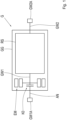
- Fig. 1 shows a schematic view of a transmission G for a motor vehicle.
- the transmission G has a housing GG, a Wheel set RS as well as a drive shaft GW1 and an output shaft GW2.
- the wheel set RS is used to form several gears between the drive shaft GW1 and the output shaft GW2.
- the gearbox G also has an electric machine EM, the rotor of which is operatively connected to the drive shaft GW1.
- the drive shaft GW1 is connected to a connecting shaft AN of the gearbox G via a clutch K0.
- a drive interface GW1A is formed on the connecting shaft AN.
- An output interface GW2A is formed on the output shaft GW2.
- the drive interface GW1A and the output interface GW2A are arranged at opposite ends of the gearbox G.
- the housing GG encloses not only the wheel set RS but also the separating clutch K0 and the electric machine EM.
- Fig. 2 shows a schematic view of a transmission G, which essentially corresponds to the one in Fig.1 corresponds to the gearbox G shown.
- the rotor of the electric machine EM is now operatively connected to the output shaft GW2.
- the connecting shaft AN and the separating clutch K0 are omitted, so that the drive interface GW1A is formed on the drive shaft GW1.
- Fig. 3 shows a schematic view of a transmission G, which essentially corresponds to the one in Fig.1 shown gearbox G.
- the rotor of the electric machine EM is now operatively connected to an element RSx of the gear set RS.
- the connecting shaft AN and the separating clutch K0 are omitted, so that the drive interface GW1A is formed on the drive shaft GW1.
- the in Fig. 1 to Fig. 3 The gearboxes G shown are only examples.
- a separating clutch K0 and a connecting shaft AN can also be provided.
- Each of the transmissions shown as examples could have a torque converter which is arranged between the connecting shaft AN and the gear set RS.
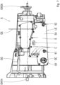
- Fig. 4 shows a side view of a gearbox G.
- the structure of the gearbox G can be exemplary based on one of the Fig. 1 to Fig. 3
- the gear G has an electric machine EM, which is arranged inside the housing GG and therefore in Fig. 4 is not visible.
- the housing GG has an area GGE on an outer wall GGA, which is connected by means of a Fig. 4 not shown power electronics module LE.
- the area GGE is limited by a flange surface FF, which forms the mechanical interface between the housing GG and the power electronics module LE.
- a phase interface AC2 is arranged, which is assigned to the electrical machine EM arranged inside the housing GG.
- the GGE area is located between a lower edge UK of the gearbox housing GG and half the overall height GH2 of the gearbox housing GG.
- the GGE area extends in sections above the lowest third GH3 of the overall height GH of the gearbox housing GG.
- the phase interface AC2 is partially located in a section of the GGE area that extends above the lowest third GH3 of the overall height GH of the gearbox housing GG.
- Fig. 5 shows a sectional view of the transmission G according to the invention, wherein the power electronics module LE is mounted on the transmission housing GG.
- the Fig. 4 The specified cutting plane A passes through the wheelset RS, so that the wheelset RS is in Fig. 5 is partially visible.
- the power electronics module LE has a carrier element S with an inner side SI and an outer side SA, a direct current connection DC, an inverter INV and an alternating current connection AC connected to the phase interface AC2.
- the inverter INV is attached to the inner side SI of the carrier element S.
- the area GGE of the housing GG and the inner side SI of the carrier element S form a dry space TR to accommodate the inverter INV.
- the area GGE of the housing GG separates the wheel set RS from the dry space TR,
- the alternating voltage connection AC is arranged inside the dry space TR and is only partially visible in the given sectional view.
- a section of the alternating voltage connection AC is located above the lowest third GH3 of the overall height GH of the gear housing GG.
- the direct voltage connection DC is arranged on the outside SA of the support element S and is located inside the lowest third GH3 of the overall height GH of the gear housing GG.
- Fig. 6 shows a side view of the transmission G according to the invention, in which, in contrast to the illustration in Fig. 4 the power electronics module LE is mounted on the housing GG. It can be clearly seen that the power electronics module LE extends predominantly along the lowest third GH3 of the overall height GH of the gearbox housing GG.
- the carrier element S has several openings which are closed by covers C. If the covers C are removed, the AC voltage connection AC arranged on the inside SI of the carrier element S is accessible from the outside SA.
- the power electronics module LE has a cooling water supply connection K1 and a cooling water discharge connection K2, which are arranged on the outside SA of the carrier element S. Cooling water can be supplied to a heat exchanger of the power electronics module LE via the cooling water supply connection K1.
- the heat exchanger is in thermal contact with power semiconductors of the inverter INV, so that the power semiconductors can release thermal energy to the heat exchanger.
- the supplied cooling water is heated in the heat exchanger and is led out of the power electronics module LE via the cooling water discharge connection K2.
- the cooling water heated in this way can be fed to another heat exchanger, preferably outside the gearbox.
- the power electronics module LE has a signal connector I on the outside SA of the carrier element S.
- the signal connector I is used for signal transmission between an element of the power electronics module LE, in particular a control of the inverter INV, and a Fig. 6 not shown, the transmission-external control unit ECU is installed.
- the power electronics module LE also has a pressure compensation element D, by means of which the dry chamber TR is connected to the environment. This can prevent moisture from accumulating in the dry chamber TR, caused by a pressure difference between the environment and the dry chamber TR.
- Fig. 7 shows a side view of a variant of the transmission G according to the invention, which essentially corresponds to the Fig. 6 shown gearbox G.
- the carrier element S now has a connection for a vent line DS.
- the drying chamber TR is connected to the environment by means of the vent line DS.
- the free end of the vent line DS can be arranged in a high and water-protected area in the motor vehicle which is equipped with such a transmission G.
- Fig. 8 shows a schematic view of a motor vehicle with the transmission G according to the invention.
- the transmission G is connected to an internal combustion engine VM via the drive interface GW1A.
- the transmission G is connected to a differential gear (not shown) via the output interface GW2A, via which the power applied to the output shaft GW2 is distributed to drive wheels DW of the motor vehicle.
- the motor vehicle has a control unit ECU, which is designed to control hybrid drive functions of the motor vehicle.
- the control unit ECU is connected to the combustion engine VM and via the signal connector I to the power electronics module LE of the transmission G for signal transmission.
- the control unit ECU can be connected to other components of the motor vehicle, for example to a battery.
Landscapes
- Engineering & Computer Science (AREA)
- Mechanical Engineering (AREA)
- Transportation (AREA)
- Chemical & Material Sciences (AREA)
- Combustion & Propulsion (AREA)
- General Engineering & Computer Science (AREA)
- Power Engineering (AREA)
- Electric Propulsion And Braking For Vehicles (AREA)
- Hybrid Electric Vehicles (AREA)
- General Details Of Gearings (AREA)
- Arrangement Of Transmissions (AREA)
Description
- Die Erfindung betrifft ein Getriebe für ein Kraftfahrzeug, sowie ein Kraftfahrzeug mit einem solchen Getriebe. Ein Getriebe bezeichnet hier insbesondere ein mehrgängiges Getriebe, bei dem eine Vielzahl von Gängen, also feste Übersetzungsverhältnisse zwischen einer Antriebswelle und einer Abtriebswelle des Getriebes, durch Schaltelemente vorzugsweise automatisch schaltbar sind. Bei den Schaltelementen handelt es sich hier beispielsweise um Kupplungen oder Bremsen. Derartige Getriebe finden vor allem in Kraftfahrzeugen Anwendung, um die Drehzahl- und Drehmomentabgabecharakteristik der Antriebseinheit den Fahrwiderständen des Fahrzeugs in geeigneter Weise anzupassen.
- Die Offenlegung
DE 10 2010 002 746 A1 der Anmelderin beschreibt ein solches Getriebe, welches eine innerhalb einer Getriebeglocke des Getriebegehäuses angeordnete elektrische Maschine aufweist. Die elektrische Maschine ist mit einer zugeordneten Leistungselektronik gekoppelt, wobei die Leistungselektronik in einer Deckelkonstruktion des Getriebegehäuses vorgesehen ist und über eine Phasenschnittstelle mit der elektrischen Maschine verbunden ist. Die Deckelkonstruktion ist im Bereich der Getriebeglocke radial unterhalb der elektrischen Maschine an dem Getriebegehäuse lösbar befestigt. Durch eine derartige Anbindung der Leistungselektronik wird die Bodenfreiheit eines Kraftfahrzeugs mit einem solchen Getriebe reduziert. - Die
DE 11 2015 004 417 T5 beschreibt eine Fahrzeugantriebs-Vorrichtung, die eine elektrische Maschine und einen Wechselrichter aufweist. Der Wechselrichter ist auf einem Wechselrichter-Gehäuse angeordnet, welcher durch einen Gehäusedeckel verschlossen ist. Das Wechselrichter-Gehäuse ist mit einem Grundkörper-Gehäuse verbunden. - Die
JP 2015-220830A - Die
DE 11 2009 000 022 T5 beschreibt eine Hybridantriebseinheit mit einem Hauptkörpergehäuse, das einen mit einer Bremskraftmaschine verbundenen Verbindungsbereich aufweist und in sich eine drehende Elektromaschine aufnimmt, und einem Wechselrichtergehäuse, das integral mit dem Hauptkörpergehäuse ausgebildet ist und in sich einen Wechselrichter aufnimmt, der die drehende Elektromaschine steuert. - Es ist daher Aufgabe der Erfindung das im Stand der Technik bekannte Getriebe derart weiterzuentwickeln, sodass das Getriebe eine kompakte Bauhöhe aufweist ohne die Außenabmessungen des Getriebes wesentlich zu vergrößern.
- Die Aufgabe wird gelöst durch die Merkmale des Patentanspruchs 1. Vorteilhafte Ausgestaltungen ergeben sich aus den Unteransprüchen, der Beschreibung sowie aus den Figuren.
- Das Getriebe weist ein Gehäuse, einen innerhalb des Gehäuses angeordneten Radsatz zur Bildung mehrerer Gänge zwischen einer Antriebswelle und einer Abtriebswelle des Getriebes, eine elektrische Maschine sowie ein Leistungselektronikmodul auf. Die elektrische Maschine ist mit der Antriebswelle, mit der Abtriebswelle oder mit einem Element des Radsatzes wirkverbunden.
- Das Leistungselektronikmodul weist ein Trägerelement mit einer Innenseite und mit einer Außenseite, einen Gleichspannungsanschluss, einen Wechselrichter sowie einen Wechselspannungsanschluss auf. Der Wechselspannungsanschluss ist mit einer Phasenschnittstelle der elektrischen Maschine verbunden, bevorzugt lösbar verbunden.
- Das Gehäuse weist an einer Außenwand einen Bereich zur Aufnahme des Leistungselektronikmoduls auf. Dieser Bereich ist durch das Trägerelement des Leistungselektronikmoduls verschließbar. Die Außenwand des Gehäuses und die Innenseite des Trägerelements bilden einen Trockenraum, in dem der Wechselrichter aufgenommen ist. Der Wechselrichter ist an dem Trägerelement befestigt. Der Bereich des Gehäuses, an dem das Leistungselektronikmodul aufgenommen ist, trennt zumindest abschnittsweise den Radsatz des Getriebes vom Trockenraum des Wechselrichters.
- Durch das Zusammenwirken von Getriebegehäuse und Trägerelement des Leistungselektronikmoduls kann ein separates Gehäuse des Leistungselektronikmoduls entfallen. Durch die Ausbildung des Trockenraums im Bereich des Radsatzes kann der zur Verfügung stehende Bauraum besonders effizient genutzt werden. Denn der Radsatz weist häufig einen runden, oder zumindest abgerundeten Querschnitt auf, welcher kleiner ist als der Querschnitt der elektrischen Maschine. Durch Ausnutzung des Bauraums im Bereich des Radsatzes für das Leistungselektronikmodul vergrößert sich der gesamte Querschnitt des Getriebes daher nur geringfügig.
- Die Leistungselektronikmodul ist seitlich am Getriebe angeordnet. Unter "seitlich" wird hierbei eine Anordnung verstanden, bei der die Leistungselektronik nicht oberhalb oder unterhalb des Getriebegehäuses angeordnet ist, sondern an einer Außenseite des Getriebegehäuses. Bei einem Getriebe für einen parallel zur Fahrtrichtung ausgerichteten Kraftfahrzeug-Antriebsstrang ist das Leistungselektronikmodul somit zu einer Fahrzeugseite hin ausgerichtet.
- Gemäß einer bevorzugten Ausgestaltung weist das Getriebe eine Antriebswellenschnittstelle und eine Abtriebswellenschnittstelle auf. Über die Antriebswellenschnittstelle ist Leistung von einer getriebe-externen Antriebseinheit auf die Antriebswelle des Getriebes übertragbar, gegebenenfalls durch Schließen einer Trennkupplung oder einer Anfahrkupplung. Über die Abtriebswellenschnittstelle ist Leistung von der Abtriebswelle zu Antriebsrädern eines mit dem Getriebe ausgestatteten Kraftfahrzeugs übertragbar. Der Leistungspfad zwischen Abtriebswelle und Antriebsrädern kann ein oder mehrere Differentialgetriebe sowie weitere Antriebsstrangwellen umfassen. Die Antriebsschnittstelle und die Abtriebsschnittstelle sind an gegenüberliegenden Enden des Getriebes angeordnet. Das Leistungselektronikmodul ist zwischen der Antriebsschnittstelle und der Abtriebsschnittstelle angeordnet, und erstreckt sich zumindest abschnittsweise bis oberhalb des untersten Drittels der Bauhöhe des Getriebegehäuses. Unter "Bauhöhe" wird hierbei die vertikale Abmessung des Getriebegehäuses in der Einbaulage im Kraftfahrzeug verstanden.
- Vorzugsweise befindet sich der Gehäusebereich zur Aufnahme des Leistungselektronikmoduls zwischen einer Unterkante des Getriebegehäuses und der halben Bauhöhe des Getriebegehäuses. Zumindest abschnittsweise erstreckt sich der Gehäusebereich oberhalb des untersten Drittels der Bauhöhe des Getriebegehäuses. Bei einer solchen Ausgestaltung kann zumindest ein Teil des Wechselspannungsanschlusses in jenem Abschnitt des Leistungselektronikmoduls angeordnet sein, welcher sich oberhalb des untersten Drittels der Bauhöhe des Getriebegehäuses erstreckt.
- Vorzugsweise weist das Leistungselektronikmodul abschnittsweise eine geringere Bauhöhe als das Drittel der Bauhöhe des Getriebegehäuses auf. Bei einer solchen Ausgestaltung kann der Gleichspannungsanschluss in jenem Abschnitt des Leistungselektronikmoduls angeordnet sein, welcher eine geringere Bauhöhe als das Drittel der Bauhöhe des Getriebegehäuses aufweist.
- Das Leistungselektronikmodul erstreckt sich zu einem überwiegenden Anteil entlang des untersten Drittels der Bauhöhe des Getriebegehäuses. In anderen Worten ist ein Großteil des Leistungselektronikmoduls entlang des untersten Drittels des Getriebegehäuses angeordnet. Dadurch wird ein Innenraum des Kraftfahrzeugs mit einem solchen Getriebe nicht verkleinert.
- Vorzugsweise weist das Trägerelement Öffnungen auf, welche mittels einem oder mehreren Deckeln verschließbar sind. Durch die Öffnungen können Montage und/oder Wartungstätigkeiten am Getriebe ermöglicht werden, ohne das Leistungselektronikmodul vom Getriebe zu lösen. Beispielsweise kann der Wechselspannungsanschluss an der Innenseite des Trägerelements angeordnet sein, wobei der Wechselspannungsanschluss durch die Öffnungen hindurch ausgehend von einer Außenseite des Trägerelements zugänglich ist. Dies ermöglicht eine Kontaktierung des Wechselspannungsanschlusses mit der Phasenschnittstelle der elektrischen Maschine nach einer Befestigung des Leistungselektronikmoduls am Getriebegehäuse.
- Gemäß einer bevorzugten Ausgestaltung ist der Gleichspannungsanschluss an der Außenseite des Trägerelements angeordnet. Dies erleichtert das Herstellen einer elektrisch leitenden Verbindung zwischen einer Batterie des Kraftfahrzeugs und dem Gleichspannungsanschluss bei der Montage des Getriebes in das Kraftfahrzeug.
- Vorzugsweise weist das Leistungselektronikmodul einen Kühlwasser-Zufuhr-Anschluss und einen Kühlwasser-Abfuhr-Anschluss auf, welche an der Außenseite des Trägerelements angeordnet sind. Über den Kühlwasser-Zufuhr-Anschluss kann dem Leistungselektronikmodul Kühlwasser zugeführt werden, insbesondere zum Kühlen der Leistungshalbleiter des Wechselrichters. Über den Kühlwasser-Abfuhr-Anschluss kann das Kühlwasser aus dem Leistungselektronikmodul wieder herausgeführt werden.
- Vorzugsweise weist das Leistungselektronikmodul einen Signalstecker auf, welcher an der Außenseite des Trägerelements angeordnet ist. Der Signalstecker ist zur Signalübertragung zwischen einem Element des Leistungselektronikmoduls und einer getriebe-externen Steuereinheit eingerichtet.
- Durch Vorsehen der verschiedenen Schnittstellen des Leistungselektronikmoduls an dessen Trägerelement kann das Leistungselektronikmodul fertig geprüft und vormontiert am Getriebegehäuse befestigt werden.
- Gemäß einer bevorzugten Ausgestaltung weist das Trägerelement ein Druckausgleichselement auf, mittels dem der Trockenraum mit der Umgebung verbunden ist. Dadurch kann ein Ansammeln von Feuchtigkeit im Trockenraum, hervorgerufen durch einen Druckunterschied zwischen Umgebung und Trockenraum, vermieden werden. Alternativ dazu kann das Trägerelement einen Anschluss für eine Entlüftungsleitung aufweisen, mittels dem der Trockenraum mit der Umgebung verbunden ist. Das freie Ende der Entlüftungsleitung kann an einem im Kraftfahrzeug, welches mit einem solchen Getriebe ausgestattet ist, hoch gelegenen und wassergeschützten Bereich angeordnet sein. Gemäß einer weiteren Alternative kann der Trockenraum über zumindest eine Bohrung im Gehäuse mit der Umgebung verbunden sein. Das freie Ende dieser Bohrung ist vorzugsweise an einem hoch gelegenen und wassergeschützten Bereich des Getriebes angeordnet. Die Entlüftung des Trockenraums erfolgt bei einer solchen Ausgestaltung über diese Bohrung.
- Das Getriebe kann Bestandteil eines Kraftfahrzeugs sein. Das Kraftfahrzeug weist neben dem Getriebe auch einen Verbrennungsmotor auf, welche über einen Torsionsschwingungsdämpfer mit der Antriebswelle des Getriebes drehelastisch verbunden, bzw. verbindbar sein kann. Die Abtriebswelle des Getriebes ist mit einem getriebe-internen oder getriebe-externen Differentialgetriebe antriebswirkverbunden, welches mit Rädern des Kraftfahrzeugs wirkverbunden ist. Das Kraftfahrzeug mit dem Getriebe ermöglicht mehrere Antriebsmodi des Kraftfahrzeugs. In einem elektrischen Fahrbetrieb wird das Kraftfahrzeug von der elektrischen Maschine des Getriebes angetrieben. In einem verbrennungsmotorischen Betrieb wird das Kraftfahrzeug vom Verbrennungsmotor angetrieben. In einem hybridischen Betrieb wird das Kraftfahrzeug sowohl vom Verbrennungsmotor als auch von der elektrischen Maschine des Getriebes angetrieben.
- Ausführungsbeispiele der Erfindung sind nachfolgend anhand der beigefügten Figuren detailliert beschrieben. Es zeigen:
-
Fig. 1 bis Fig.3 je eine schematische Ansicht eines Getriebes für ein Kraftfahrzeug; -
Fig. 4 eine Seitenansicht eines erfindungsgemäßen Getriebes mit demontiertem Leistungselektronikmodul; -
Fig. 5 eine Schnittansicht des erfindungsgemäßen Getriebes mit montiertem Leistungselektronikmodul; -
Fig. 6 eine Seitenansicht des erfindungsgemäßen Getriebes mit montiertem Leistungselektronikmodul; -
Fig. 7 eine Seitenansicht einer Variante des erfindungsgemäßen Getriebes mit montiertem Leistungselektronikmodul; und -
Fig. 8 eine schematische Ansicht eines Kraftfahrzeugs mit dem erfindungsgemäßen Getriebe. -
Fig. 1 zeigt eine schematische Ansicht eines Getriebes G für ein Kraftfahrzeug. Das Getriebe G weist ein Gehäuse GG, einen innerhalb des Gehäuses GG angeordneten Radsatz RS sowie eine Antriebswelle GW1 und eine Abtriebswelle GW2 auf. Der Radsatz RS dient zur Bildung mehrerer Gänge zwischen der Antriebswelle GW1 und der Abtriebswelle GW2. Das Getriebe G weist ferner eine elektrische Maschine EM auf, deren Rotor mit der Antriebswelle GW1 wirkverbunden ist. Die Antriebswelle GW1 ist über eine Kupplung K0 mit einer Anschlusswelle AN des Getriebes G verbunden. An der Anschlusswelle AN ist eine Antriebsschnittstelle GW1A ausgebildet. An der Abtriebswelle GW2 ist eine Abtriebsschnittstelle GW2A ausgebildet. Antriebsschnittstelle GW1A und Abtriebsschnittstelle GW2A sind an gegenüberliegenden Enden des Getriebes G angeordnet. Das Gehäuse GG umschließt neben dem Radsatz RS auch die Trennkupplung K0 und die elektrische Maschine EM. -
Fig. 2 zeigt eine schematische Ansicht eines Getriebes G, welches im Wesentlichen dem inFig.1 dargestellten Getriebe G entspricht. Der Rotor der elektrischen Maschine EM ist nun mit Abtriebswelle GW2 wirkverbunden. Die Anschlusswelle AN und die Trennkupplung K0 entfallen, sodass die Antriebsschnittstelle GW1A an der Antriebswelle GW1 ausgebildet ist. -
Fig. 3 zeigt eine schematische Ansicht eines Getriebes G, welches im Wesentlichen dem inFig.1 dargestellten Getriebe G entspricht. Der Rotor der elektrischen Maschine EM ist nun einem Element RSx des Radsatzes RS wirkverbunden. Die Anschlusswelle AN und die Trennkupplung K0 entfallen, sodass die Antriebsschnittstelle GW1A an der Antriebswelle GW1 ausgebildet ist. - Die in
Fig. 1 bis Fig. 3 dargestellten Getriebe G sind lediglich beispielhaft anzusehen. So könnte bei Ausführungen gemäßFig. 2 undFig. 3 ebenso eine Trennkupplung K0 und eine Anschlusswelle AN vorgesehen sein. Jedes der beispielhaft gezeigten Getriebe könnte einen Drehmomentwandler aufweisen, welcher zwischen der Anschlusswelle AN und dem Radsatz RS angeordnet ist. -
Fig. 4 zeigt eine Seitenansicht eines Getriebes G. Der Aufbau des Getriebes G kann beispielhaft einem der inFig. 1 bis Fig. 3 dargestellten Ausführungen entsprechen. Das Getriebe G weist jedenfalls eine elektrische Maschine EM auf, welche im Inneren des Gehäuses GG angeordnet, und daher inFig. 4 nicht sichtbar ist. Das Gehäuse GG weist an einer Außenwand GGA einen Bereich GGE auf, welcher mittels eines inFig. 4 nicht dargestellten Leistungselektronikmoduls LE verschließbar ist. Der Bereich GGE wird durch eine Flanschfläche FF begrenzt, welche die mechanische Schnittstelle zwischen dem Gehäuse GG und dem Leistungselektronikmodul LE bildet. Im Bereich GGE ist eine Phasenschnittstelle AC2 angeordnet, welche der innerhalb des Gehäuses GG angeordneten elektrischen Maschine EM zugeordnet ist. - Der Bereich GGE befindet sich zwischen einer Unterkante UK des Getriebegehäuses GG und der halben Bauhöhe GH2 des Getriebegehäuses GG. Abschnittsweise erstreckt sich der Bereich GGE oberhalb des untersten Drittels GH3 der Bauhöhe GH des Getriebegehäuses GG. Die Phasenschnittstelle AC2 befindet sich teilweise in einem Abschnitt des Bereichs GGE, welcher sich oberhalb des untersten Drittels GH3 der Bauhöhe GH des Getriebegehäuses GG erstreckt.
-
Fig. 5 zeigt eine Schnittansicht des erfindungsgemäßen Getriebes G, wobei das Leistungselektronikmodul LE am Getriebegehäuse GG montiert ist. Die inFig. 4 angegebene Schnittebene A verläuft durch den Radsatz RS hindurch, sodass der Radsatz RS inFig. 5 teilweise sichtbar ist. Das Leistungselektronikmodul LE weist ein Trägerelement S mit einer Innenseite SI und mit einer Außenseite SA, einen Gleichspannungsanschluss DC, einen Wechselrichter INV sowie einen mit der Phasenschnittstelle AC2 verbundenen Wechselspannungsanschluss AC auf. Der Wechselrichter INV ist an der Innenseite SI des Trägerelement S befestigt. Der Bereich GGE des Gehäuses GG und die Innenseite SI des Trägerelements S bilden einen Trockenraum TR zur Aufnahme des Wechselrichters INV. In der Schnittebene A trennt den Bereich GGE des Gehäuse GG den Radsatz RS vom Trockenraum TR, - Der Wechselspannungsanschluss AC ist innerhalb des Trockenraums TR angeordnet, und in der gegebenen Schnittansicht nur teilweise sichtbar. Ein Abschnitt des Wechselspannungsanschlusses AC befindet sich oberhalb des untersten Drittels GH3 der Bauhöhe GH des Getriebegehäuses GG. Der Gleichspannungsanschluss DC ist an der Außenseite SA des Trägerelements S angeordnet und befindet innerhalb des untersten Drittels GH3 der Bauhöhe GH des Getriebegehäuses GG.
-
Fig. 6 zeigt eine Seitenansicht des erfindungsgemäßen Getriebes G, wobei im Unterschied zur Darstellung inFig. 4 das Leistungselektronikmodul LE am Gehäuse GG montiert ist. Darin ist gut zu erkennen, dass sich das Leistungselektronikmodul LE zu einem überwiegenden Anteil entlang des untersten Drittels GH3 der Bauhöhe GH des Getriebegehäuses GG erstreckt. Das Trägerelement S weist mehrere Öffnungen auf, welche mittels Deckeln C verschlossen sind. Werden die Deckel C entfernt, so ist der an der Innenseite SI des Trägerelements S angeordnete Wechselspannungsanschluss AC von der Außenseite SA zugänglich. - Das Leistungselektronikmodul LE weist einen Kühlwasser-Zufuhr-Anschluss K1 und einen Kühlwasser-Abfuhr-Anschluss K2 auf, welche an der Außenseite SA des Trägerelements S angeordnet sind. Über den Kühlwasser-Zufuhr-Anschluss K1 kann einem Wärmetauscher des Leistungselektronikmoduls LE Kühlwasser zugeführt werden. Der Wärmetauscher ist in thermischem Kontakt mit Leistungshalbleitern des Wechselrichters INV, sodass die Leistungshalbleiter an den Wärmetauscher Wärmeenergie abgeben können. Im Wärmetauscher erwärmt sich das zugeführte Kühlwasser, welches über den Kühlwasser-Abfuhr-Anschluss K2 aus dem Leistungselektronikmodul LE herausgeleitet wird. Das derart erwärmte Kühlwasser kann einem bevorzugt getriebe-externen weiteren Wärmetauscher zugeführt werden.
- Das Leistungselektronikmodul LE weist an der Außenseite SA des Trägerelements S einen Signalstecker I auf. Der Signalstecker I ist zur Signalübertragung zwischen einem Element des Leistungselektronikmoduls LE, insbesondere einer Steuerung des Wechselrichters INV, und einer in
Fig. 6 nicht dargestellten getriebe-externen Steuereinheit ECU eingerichtet. Das Leistungselektronikmodul LE weist ferner ein Druckausgleichselement D auf, mittels dem der Trockenraum TR mit der Umgebung verbunden ist. Dadurch kann ein Ansammeln von Feuchtigkeit im Trockenraum TR, hervorgerufen durch einen Druckunterschied zwischen Umgebung und Trockenraum TR, vermieden werden. -
Fig. 7 zeigt eine Seitenansicht einer Variante des erfindungsgemäßen Getriebes G, welches im Wesentlichen dem inFig. 6 dargestellten Getriebe G entspricht. Anstatt dem Druckausgleichselement D weist das Trägerelement S nun einen Anschluss für eine Entlüftungsleitung DS auf. Mittels der Entlüftungsleitung DS ist der Trockenraum TR mit der Umgebung verbunden. Das freie Ende der Entlüftungsleitung DS kann an einem im Kraftfahrzeug, welches mit einem solchen Getriebe G ausgestattet ist, hoch gelegenen und wassergeschützten Bereich angeordnet sein. -
Fig. 8 zeigt eine schematische Ansicht eines Kraftfahrzeugs mit dem erfindungsgemäßen Getriebe G. Das Getriebe G ist über die Antriebsschnittstelle GW1A mit einem Verbrennungsmotor VM verbunden. Über die Abtriebsschnittstelle GW2A ist das Getriebe G mit einem nicht dargestellten Differentialgetriebe verbunden, über welches die an der Abtriebswelle GW2 anliegende Leistung auf Antriebsräder DW des Kraftfahrzeugs verteilt wird. - Das Kraftfahrzeug weist eine Steuereinheit ECU auf, welche zur Steuerung von Hybridantriebsfunktionen des Kraftfahrzeugs eingerichtet ist. Die Steuereinheit ECU ist dazu mit dem Verbrennungsmotor VM und über den Signalstecker I mit dem Leistungselektronikmodul LE des Getriebes G zur Signalübertragung verbunden. Die Steuereinheit ECU kann mit weiteren Komponenten des Kraftfahrzeugs verbunden sein, beispielsweise mit einer Batterie.
-
- G
- Getriebe
- GW1
- Antriebswelle
- GW2
- Abtriebswelle
- GW1A
- Antriebsschnittstelle
- GW2A
- Abtriebsschnittstelle
- RS
- Radsatz
- RSx
- Radsatzelement
- EM
- Elektrische Maschine
- AC2
- Phasenschnittstelle der elektrischen Maschine
- GG
- Gehäuse
- GGE
- Bereich des Gehäuses
- GGA
- Außenwand des Gehäuses
- FF
- Flanschfläche
- UK
- Unterkante des Gehäuses
- GH
- Bauhöhe des Gehäuses
- GH2
- Halbe Bauhöhe des Gehäuses
- GH3
- Drittel der Bauhöhe des Gehäuses
- LE
- Leistungselektronikmodul
- S
- Trägerelement
- SI
- Innenseite des Trägerelements
- SA
- Außenseite des Trägerelements
- DC
- Gleichspannungsanschluss
- AC
- Wechselspannungsanschluss
- INV
- Wechselrichter
- A
- Schnittebene
- TR
- Trockenraum
- C
- Deckel
- K1
- Kühlwasser-Zufuhr-Anschluss
- K2
- Kühlwasser-Abfuhr-Anschluss
- I
- Signalstecker
- ECU
- Steuereinheit
- D
- Druckausgleichselement
- DS
- Entlüftungsleitung
- VM
- Verbrennungsmotor
- K0
- Trennkupplung
- AN
- Anschlusswelle
- DW
- Antriebsrad
Claims (15)
- Getriebe (G) für ein Kraftfahrzeug, wobei das Getriebe (G) ein Gehäuse (GG), einen innerhalb des Gehäuses (GG) angeordneten Radsatz (RS) zur Bildung mehrerer Gänge zwischen einer Antriebswelle (GW1) und einer Abtriebswelle (GW2) des Getriebes (G), eine mit der Antriebswelle (GW1), der Abtriebswelle (GW2) oder einem Element (RSx) des Radsatzes (RS) wirkverbundene elektrische Maschine (EM) sowie ein Leistungselektronikmodul (LE) aufweist,- wobei das Leistungselektronikmodul (LE) ein Trägerelement (S) mit einer Innenseite (SI) und mit einer Außenseite (SA), einen Gleichspannungsanschluss (DC), einen Wechselrichter (INV) sowie einen mit einer Phasenschnittstelle (AC2) der elektrischen Maschine (EM) verbundenen Wechselspannungsanschluss (AC) aufweist,- wobei das Gehäuse (GG) an einer Außenwand (GGA) einen Bereich (GGE) zur Aufnahme des Leistungselektronikmoduls (LE) aufweist, welcher durch das Trägerelement (S) des Leistungselektronikmoduls (LE) verschließbar ist,- wobei der Bereich (GGE) des Gehäuses (GG) und die Innenseite (SI) des Trägerelements (S) einen Trockenraum (TR) zur Aufnahme des Wechselrichters (INV) bilden, welcher an dem Trägerelement (S) befestigt ist, und- wobei der Bereich (GGE) des Gehäuses (GG) zumindest abschnittsweise den Radsatz (RS) vom Trockenraum (TR) trennt,- wobei das Leistungselektronikmodul (LE) seitlich am Gehäuse (GG) angeordnet ist, und sich zu einem überwiegenden Anteil entlang eines untersten Drittels (GH3) einer Bauhöhe (GH) des Gehäuses (GG) erstreckt.
- Getriebe (G) nach Anspruch 1, dadurch gekennzeichnet, dass das Getriebe (G) eine Antriebsschnittstelle (GW1A) und eine Abtriebsschnittstelle (GW2A) aufweist, wobei die Antriebsschnittstelle (GW1A) und die Abtriebsschnittstelle (GW2A) an gegenüberliegenden Enden des Getriebes (G) angeordnet sind, wobei das Leistungselektronikmodul (LE) zwischen der Antriebsschnittstelle (GW1A) und
der Abtriebsschnittstelle (GW2A) angeordnet ist und sich zumindest abschnittsweise bis oberhalb des untersten Drittels (GH3) der Bauhöhe (GH) des Gehäuses (GG) erstreckt. - Getriebe (G) nach Anspruch 1 oder Anspruch 2, dadurch gekennzeichnet, dass sich der Bereich (GGE) zur Aufnahme des Leistungselektronikmoduls (LE) zwischen einer Unterkante (UK) des Gehäuses (GG) und einer halben Bauhöhe (GH2) des Gehäuses (GG) befindet, wobei sich der Bereich (GGE) zumindest abschnittsweise oberhalb des untersten Drittels (GH3) der Bauhöhe (GH) des Gehäuses (GG) erstreckt.
- Getriebe (G) nach Anspruch 3, dadurch gekennzeichnet, dass zumindest ein Teil des Wechselspannungsanschlusses (AC) in jenem Abschnitt des Leistungselektronikmoduls (LE) angeordnet ist, welcher sich oberhalb des untersten Drittels (GH3) der Bauhöhe (GH) des Gehäuses (GG) erstreckt.
- Getriebe (G) nach Anspruch 3 oder Anspruch 4, dadurch gekennzeichnet, dass das Leistungselektronikmodul (LE) abschnittsweise eine geringere Bauhöhe aufweist als das Drittel (GH3) der Bauhöhe (GH) des Gehäuses (GG).
- Getriebe (G) nach Anspruch 5, dadurch gekennzeichnet, dass der Gleichspannungsanschluss (DC) in jenem Abschnitt des Leistungselektronikmoduls (LE) angeordnet ist, welcher eine geringere Bauhöhe (LEH) aufweist als das Drittel (GH3) der Bauhöhe (GH) des Gehäuses (GG).
- Getriebe (G) nach einem der vorangehenden Ansprüche, dadurch gekennzeichnet, dass das Trägerelement (S) Öffnungen aufweist, welche mittels einem oder mehreren Deckeln (C) verschließbar sind.
- Getriebe (G) nach Anspruch 7, dadurch gekennzeichnet, dass der Wechselspannungsanschluss (AC) an der Innenseite (SI) des Trägerelements (S) angeordnet ist, und ausgehend von einer Außenseite (SA) des Trägerelements (S) durch die Öffnungen zugänglich ist.
- Getriebe (G) nach einem der vorangehenden Ansprüche, dadurch gekennzeichnet, dass der Gleichspannungsanschluss (DC) an der Außenseite (SA) des Trägerelements (S) angeordnet ist.
- Getriebe (G) nach einem der vorangehenden Ansprüche, dadurch gekennzeichnet, dass das Leistungselektronikmodul (LE) einen Kühlwasser-Zufuhr-Anschluss (K1) und einen Kühlwasser-Abfuhr-Anschluss (K2) aufweist, welche an der Außenseite (SA) des Trägerelements (S) angeordnet sind.
- Getriebe (G) nach einem der vorangehenden Ansprüche, dadurch gekennzeichnet, dass das Leistungselektronikmodul (LE) an der Außenseite (SA) des Trägerelements (S) einen Signalstecker (I) aufweist, der zur Signalübertragung zwischen einem Element des Leistungselektronikmoduls (LE) und einer getriebe-externen Steuereinheit (ECU) eingerichtet ist.
- Getriebe (G) nach einem der vorangehenden Ansprüche, dadurch gekennzeichnet, dass das Trägerelement (S) ein Druckausgleichselement (D) aufweist, mittels dem der Trockenraum (TR) mit der Umgebung verbunden ist.
- Getriebe (G) nach einem der Ansprüche 1 bis 11, dadurch gekennzeichnet, dass das Trägerelement (S) einen Anschluss für eine Entlüftungsleitung (DS) aufweist.
- Getriebe (G) nach einem der Ansprüche 1 bis 11, dadurch gekennzeichnet, dass der Trockenraum (TR) über zumindest eine Bohrung im Gehäuse (GG) mit der Umgebung verbunden ist.
- Kraftfahrzeug mit einem Getriebe (G) nach zumindest einem der Ansprüche 1 bis 14.
Applications Claiming Priority (2)
| Application Number | Priority Date | Filing Date | Title |
|---|---|---|---|
| DE102017212677.9A DE102017212677B4 (de) | 2017-07-24 | 2017-07-24 | Getriebe für ein Kraftfahrzeug |
| PCT/EP2018/067579 WO2019020314A1 (de) | 2017-07-24 | 2018-06-29 | Getriebe für ein kraftfahrzeug |
Publications (2)
| Publication Number | Publication Date |
|---|---|
| EP3658401A1 EP3658401A1 (de) | 2020-06-03 |
| EP3658401B1 true EP3658401B1 (de) | 2024-11-13 |
Family
ID=62842087
Family Applications (1)
| Application Number | Title | Priority Date | Filing Date |
|---|---|---|---|
| EP18737851.8A Active EP3658401B1 (de) | 2017-07-24 | 2018-06-29 | Getriebe für ein kraftfahrzeug |
Country Status (8)
| Country | Link |
|---|---|
| US (1) | US11325458B2 (de) |
| EP (1) | EP3658401B1 (de) |
| JP (1) | JP7457643B2 (de) |
| KR (2) | KR20200030062A (de) |
| CN (1) | CN110944868B (de) |
| CA (1) | CA3071036A1 (de) |
| DE (1) | DE102017212677B4 (de) |
| WO (1) | WO2019020314A1 (de) |
Families Citing this family (2)
| Publication number | Priority date | Publication date | Assignee | Title |
|---|---|---|---|---|
| DE102019206525A1 (de) * | 2019-05-07 | 2020-11-12 | Zf Friedrichshafen Ag | Getriebe mit Leistungselektronikmodul |
| DE102021204121A1 (de) * | 2021-04-26 | 2022-10-27 | Robert Bosch Gesellschaft mit beschränkter Haftung | Montagesequenz fuer elektrische Achsen (eAchse System) |
Citations (11)
| Publication number | Priority date | Publication date | Assignee | Title |
|---|---|---|---|---|
| DE102006005095A1 (de) * | 2006-02-04 | 2007-08-09 | Bayerische Motoren Werke Ag | Hybridgetriebe insbesondere für Fahrzeuge |
| DE112009000022T5 (de) * | 2008-02-20 | 2010-07-08 | Aisin AW Co., Ltd., Anjo | Hybridantriebseinheit |
| US8545367B2 (en) * | 2010-09-10 | 2013-10-01 | Allison Transmission, Inc. | Hybrid system |
| JP2014069755A (ja) * | 2012-09-28 | 2014-04-21 | Aisin Aw Co Ltd | 車両用駆動装置 |
| DE112013002854T5 (de) * | 2012-07-27 | 2015-02-26 | Aisin Aw Co., Ltd. | Fahrzeugantriebsvorrichtung |
| JP2015220830A (ja) * | 2014-05-16 | 2015-12-07 | 三菱電機株式会社 | 車載用電力変換装置 |
| DE112014001863T5 (de) * | 2013-05-31 | 2015-12-31 | Aisin Aw Co., Ltd. | Fahrzeugantriebsvorrichtung |
| US9441725B2 (en) * | 2014-12-02 | 2016-09-13 | Ford Global Technologies, Llc | Transmission fluid warm-up system and method |
| EP3112197A1 (de) * | 2014-04-25 | 2017-01-04 | Aisin Aw Co., Ltd. | Fahrzeugfahrvorrichtung |
| DE112015001689T5 (de) * | 2014-05-28 | 2017-01-05 | Aisin Aw Co., Ltd. | Fahrzeugantriebsvorrichtung |
| DE112015004417T5 (de) * | 2014-12-15 | 2017-07-13 | Aisin Aw Co., Ltd. | Fahrzeugantriebs-Vorrichtung |
Family Cites Families (23)
| Publication number | Priority date | Publication date | Assignee | Title |
|---|---|---|---|---|
| JPS60157563A (ja) * | 1984-12-14 | 1985-08-17 | Toyota Motor Corp | 自動変速機 |
| JPH01312252A (ja) * | 1988-06-08 | 1989-12-18 | Jatco Corp | 電子制御式自動変速機 |
| JP3545195B2 (ja) * | 1998-03-10 | 2004-07-21 | 株式会社日立ユニシアオートモティブ | 車両用自動変速機のコントロールユニット取付け構造 |
| DE19950967A1 (de) * | 1999-10-22 | 2001-05-10 | Voith Turbo Kg | Getriebebaueinheit und Steuerplattform für den Einsatz in einer Getriebebaueinheit |
| DE102007032535B4 (de) * | 2007-07-12 | 2009-09-24 | Continental Automotive Gmbh | Elektronisches Modul für eine integrierte mechatronische Getriebesteuerung |
| US8276694B2 (en) | 2008-02-26 | 2012-10-02 | Volvo Lastvagnar Ab | Arrangement for a power electronics unit in a hybrid vehicle |
| JP2009247119A (ja) * | 2008-03-31 | 2009-10-22 | Aisin Aw Co Ltd | 駆動装置 |
| JP5062484B2 (ja) | 2008-04-07 | 2012-10-31 | アイシン・エィ・ダブリュ株式会社 | 駆動装置 |
| JP4708459B2 (ja) * | 2008-07-29 | 2011-06-22 | 日立オートモティブシステムズ株式会社 | 電力変換装置 |
| DE102010002746A1 (de) | 2010-03-11 | 2011-09-15 | Zf Friedrichshafen Ag | Hybridgetriebe |
| DE102011003263A1 (de) * | 2011-01-27 | 2012-08-02 | Zf Friedrichshafen Ag | Modulares Gehäuse mit einer ersten Gehäuseeinrichtung zur Aufnahme wenigstens eines Hauptgetriebes |
| DE102012012327B4 (de) * | 2012-06-20 | 2026-02-26 | Volkswagen Aktiengesellschaft | Anordnung einer Elektromotoreinheit im Motorraum eines Kraftfahrzeuges |
| JP6079190B2 (ja) * | 2012-12-10 | 2017-02-15 | アイシン・エィ・ダブリュ株式会社 | 車両用駆動装置 |
| US9452682B2 (en) | 2013-01-18 | 2016-09-27 | GM Global Technology Operations LLC | Transmission for a vehicle |
| DE102013204784B4 (de) * | 2013-03-19 | 2018-01-11 | Robert Bosch Gmbh | Elektrische Fahrzeugachsenvorrichtung |
| JP6173763B2 (ja) * | 2013-04-26 | 2017-08-02 | 三菱重工オートモーティブサーマルシステムズ株式会社 | インバータ一体型電動圧縮機 |
| DE102015101024A1 (de) * | 2014-02-18 | 2015-08-20 | Sma Solar Technology Ag | Elektrisches und/oder elektronisches Gerät und Verfahren zum Entfeuchten eines Gehäuseinnenraums eines elektrischen und/oder elektronischen Geräts |
| DE102014208799A1 (de) * | 2014-05-09 | 2015-11-12 | Zf Friedrichshafen Ag | Getriebe mit einem Elektromotor |
| US10208853B2 (en) * | 2015-02-27 | 2019-02-19 | Brose Fahrzeugteile Gmbh & Co. Kommanditgesellschaft, Wuerzburg | Motor assembly |
| US10476341B2 (en) * | 2015-02-27 | 2019-11-12 | Brose Fahrzeugteile Gmbh & Co. Kommanditgesellschaft, Wuerzburg | Motor assembly |
| DE102015012223A1 (de) | 2015-09-18 | 2016-04-14 | Daimler Ag | Antriebsaggregat für einen Kraftwagen |
| JP6304270B2 (ja) * | 2016-01-29 | 2018-04-04 | トヨタ自動車株式会社 | 制御ユニット取付構造 |
| CN106655647A (zh) * | 2016-11-28 | 2017-05-10 | 中国第汽车股份有限公司 | 一种集成于电机的逆变器 |
-
2017
- 2017-07-24 DE DE102017212677.9A patent/DE102017212677B4/de active Active
-
2018
- 2018-06-29 EP EP18737851.8A patent/EP3658401B1/de active Active
- 2018-06-29 CN CN201880049260.4A patent/CN110944868B/zh active Active
- 2018-06-29 WO PCT/EP2018/067579 patent/WO2019020314A1/de not_active Ceased
- 2018-06-29 US US16/633,220 patent/US11325458B2/en active Active
- 2018-06-29 CA CA3071036A patent/CA3071036A1/en active Pending
- 2018-06-29 KR KR1020207001620A patent/KR20200030062A/ko not_active Ceased
- 2018-06-29 JP JP2020503767A patent/JP7457643B2/ja active Active
- 2018-06-29 KR KR1020247017708A patent/KR102680135B1/ko active Active
Patent Citations (11)
| Publication number | Priority date | Publication date | Assignee | Title |
|---|---|---|---|---|
| DE102006005095A1 (de) * | 2006-02-04 | 2007-08-09 | Bayerische Motoren Werke Ag | Hybridgetriebe insbesondere für Fahrzeuge |
| DE112009000022T5 (de) * | 2008-02-20 | 2010-07-08 | Aisin AW Co., Ltd., Anjo | Hybridantriebseinheit |
| US8545367B2 (en) * | 2010-09-10 | 2013-10-01 | Allison Transmission, Inc. | Hybrid system |
| DE112013002854T5 (de) * | 2012-07-27 | 2015-02-26 | Aisin Aw Co., Ltd. | Fahrzeugantriebsvorrichtung |
| JP2014069755A (ja) * | 2012-09-28 | 2014-04-21 | Aisin Aw Co Ltd | 車両用駆動装置 |
| DE112014001863T5 (de) * | 2013-05-31 | 2015-12-31 | Aisin Aw Co., Ltd. | Fahrzeugantriebsvorrichtung |
| EP3112197A1 (de) * | 2014-04-25 | 2017-01-04 | Aisin Aw Co., Ltd. | Fahrzeugfahrvorrichtung |
| JP2015220830A (ja) * | 2014-05-16 | 2015-12-07 | 三菱電機株式会社 | 車載用電力変換装置 |
| DE112015001689T5 (de) * | 2014-05-28 | 2017-01-05 | Aisin Aw Co., Ltd. | Fahrzeugantriebsvorrichtung |
| US9441725B2 (en) * | 2014-12-02 | 2016-09-13 | Ford Global Technologies, Llc | Transmission fluid warm-up system and method |
| DE112015004417T5 (de) * | 2014-12-15 | 2017-07-13 | Aisin Aw Co., Ltd. | Fahrzeugantriebs-Vorrichtung |
Also Published As
| Publication number | Publication date |
|---|---|
| CN110944868A (zh) | 2020-03-31 |
| JP7457643B2 (ja) | 2024-03-28 |
| EP3658401A1 (de) | 2020-06-03 |
| WO2019020314A1 (de) | 2019-01-31 |
| JP2020528528A (ja) | 2020-09-24 |
| DE102017212677B4 (de) | 2026-03-05 |
| KR20200030062A (ko) | 2020-03-19 |
| KR20240091082A (ko) | 2024-06-21 |
| CN110944868B (zh) | 2023-04-18 |
| DE102017212677A1 (de) | 2019-01-24 |
| US11325458B2 (en) | 2022-05-10 |
| KR102680135B1 (ko) | 2024-07-03 |
| US20200180423A1 (en) | 2020-06-11 |
| CA3071036A1 (en) | 2019-01-31 |
Similar Documents
| Publication | Publication Date | Title |
|---|---|---|
| EP3448706B1 (de) | Hybridmodul und antriebsanordnung für ein kraftfahrzeug | |
| DE102019132941B4 (de) | Antriebseinheit und Antriebsanordnung | |
| EP3154807B1 (de) | Modulares gehäuse für ein hybridmodul | |
| EP3478523B2 (de) | Hybridantriebsmodul für einen kraftfahrzeugantriebsstrang und kraftfahrzeugantriebsstrang | |
| DE102015217875A1 (de) | Antriebssystem mit einer elektrischen Maschine und einem Getriebe | |
| DE102008043290A1 (de) | Hybridmodul für den Hybridantriebsstrang eines Kraftfahrzeugs | |
| DE102011056431A1 (de) | Hybridantriebsstrang für Kraftfahrzeuge | |
| DE102019132942A1 (de) | Antriebseinheit und Antriebsanordnung | |
| WO2021037303A1 (de) | Elektrische antriebseinrichtung, antriebseinheit und antriebsanordnung | |
| DE102010002746A1 (de) | Hybridgetriebe | |
| EP3658401B1 (de) | Getriebe für ein kraftfahrzeug | |
| DE102013215465B4 (de) | Elektromechanische antriebseinheit | |
| EP4115500A1 (de) | Systemgehäuse für ein antriebssystem | |
| WO2015172914A1 (de) | Integration einer elektromotoreneinheit in ein getriebegehäuse | |
| EP2646713B1 (de) | Wellenadaptereinheit mit seinem entsprechenden getriebe und seiner entsprechenden antriebseinheit. | |
| DE102017109767A1 (de) | Hybridmodulgehäuse zum Beherbergen einer Elektromaschine und einer Trennkupplung sowie Hybridantriebsstrang und Montageverfahren | |
| DE102015012223A1 (de) | Antriebsaggregat für einen Kraftwagen | |
| DE102008021685B4 (de) | Kupplungssystem eines Hybrid-Antriebstranges | |
| DE102016211942A1 (de) | Hybridantriebsmodul für einen Kraftfahrzeugantriebsstrang, sowie Kraftfahrzeugantriebsstrang | |
| DE102018131680B4 (de) | Antriebsanordnung mit an Motorgehäuserückwand befestigtem Nehmerzylinder | |
| DE10109093B4 (de) | Antriebsverbindung zur Drehmomentübertragung im Antriebsstrang eines Kraftfahrzeugs | |
| DE102021206680A1 (de) | Antriebseinrichtung mit einer elektrischen Maschine | |
| WO2020052922A1 (de) | E-motorgehäuse für einen hybridantriebsstrang | |
| DE102024206401A1 (de) | Gehäuseanordnung für eine Antriebsvorrichtung | |
| EP2946960A1 (de) | Antriebsstrangmodul für ein Kraftfahrzeug |
Legal Events
| Date | Code | Title | Description |
|---|---|---|---|
| STAA | Information on the status of an ep patent application or granted ep patent |
Free format text: STATUS: UNKNOWN |
|
| STAA | Information on the status of an ep patent application or granted ep patent |
Free format text: STATUS: THE INTERNATIONAL PUBLICATION HAS BEEN MADE |
|
| PUAI | Public reference made under article 153(3) epc to a published international application that has entered the european phase |
Free format text: ORIGINAL CODE: 0009012 |
|
| STAA | Information on the status of an ep patent application or granted ep patent |
Free format text: STATUS: REQUEST FOR EXAMINATION WAS MADE |
|
| 17P | Request for examination filed |
Effective date: 20200123 |
|
| AK | Designated contracting states |
Kind code of ref document: A1 Designated state(s): AL AT BE BG CH CY CZ DE DK EE ES FI FR GB GR HR HU IE IS IT LI LT LU LV MC MK MT NL NO PL PT RO RS SE SI SK SM TR |
|
| AX | Request for extension of the european patent |
Extension state: BA ME |
|
| DAV | Request for validation of the european patent (deleted) | ||
| DAX | Request for extension of the european patent (deleted) | ||
| STAA | Information on the status of an ep patent application or granted ep patent |
Free format text: STATUS: EXAMINATION IS IN PROGRESS |
|
| 17Q | First examination report despatched |
Effective date: 20210503 |
|
| REG | Reference to a national code |
Ref country code: DE Ref legal event code: R079 Ref country code: DE Ref legal event code: R079 Ref document number: 502018015322 Country of ref document: DE Free format text: PREVIOUS MAIN CLASS: B60K0026000000 Ipc: B60K0006405000 |
|
| GRAP | Despatch of communication of intention to grant a patent |
Free format text: ORIGINAL CODE: EPIDOSNIGR1 |
|
| STAA | Information on the status of an ep patent application or granted ep patent |
Free format text: STATUS: GRANT OF PATENT IS INTENDED |
|
| RIC1 | Information provided on ipc code assigned before grant |
Ipc: B60L 15/00 20060101ALI20240523BHEP Ipc: B60K 6/547 20071001ALI20240523BHEP Ipc: B60K 17/08 20060101ALI20240523BHEP Ipc: B60K 1/00 20060101ALI20240523BHEP Ipc: B60K 6/48 20071001ALI20240523BHEP Ipc: B60K 6/40 20071001ALI20240523BHEP Ipc: H02K 11/33 20160101ALI20240523BHEP Ipc: H02K 9/19 20060101ALI20240523BHEP Ipc: H02K 7/00 20060101ALI20240523BHEP Ipc: H02K 5/00 20060101ALI20240523BHEP Ipc: B60L 50/16 20190101ALI20240523BHEP Ipc: B60L 50/13 20190101ALI20240523BHEP Ipc: B60K 6/54 20071001ALI20240523BHEP Ipc: B60K 6/405 20071001AFI20240523BHEP |
|
| INTG | Intention to grant announced |
Effective date: 20240619 |
|
| GRAS | Grant fee paid |
Free format text: ORIGINAL CODE: EPIDOSNIGR3 |
|
| GRAA | (expected) grant |
Free format text: ORIGINAL CODE: 0009210 |
|
| STAA | Information on the status of an ep patent application or granted ep patent |
Free format text: STATUS: THE PATENT HAS BEEN GRANTED |
|
| AK | Designated contracting states |
Kind code of ref document: B1 Designated state(s): AL AT BE BG CH CY CZ DE DK EE ES FI FR GB GR HR HU IE IS IT LI LT LU LV MC MK MT NL NO PL PT RO RS SE SI SK SM TR |
|
| REG | Reference to a national code |
Ref country code: GB Ref legal event code: FG4D Free format text: NOT ENGLISH |
|
| REG | Reference to a national code |
Ref country code: CH Ref legal event code: EP |
|
| REG | Reference to a national code |
Ref country code: DE Ref legal event code: R096 Ref document number: 502018015322 Country of ref document: DE |
|
| REG | Reference to a national code |
Ref country code: IE Ref legal event code: FG4D Free format text: LANGUAGE OF EP DOCUMENT: GERMAN |
|
| REG | Reference to a national code |
Ref country code: LT Ref legal event code: MG9D |
|
| REG | Reference to a national code |
Ref country code: NL Ref legal event code: MP Effective date: 20241113 |
|
| PG25 | Lapsed in a contracting state [announced via postgrant information from national office to epo] |
Ref country code: IS Free format text: LAPSE BECAUSE OF FAILURE TO SUBMIT A TRANSLATION OF THE DESCRIPTION OR TO PAY THE FEE WITHIN THE PRESCRIBED TIME-LIMIT Effective date: 20250313 Ref country code: HR Free format text: LAPSE BECAUSE OF FAILURE TO SUBMIT A TRANSLATION OF THE DESCRIPTION OR TO PAY THE FEE WITHIN THE PRESCRIBED TIME-LIMIT Effective date: 20241113 Ref country code: PT Free format text: LAPSE BECAUSE OF FAILURE TO SUBMIT A TRANSLATION OF THE DESCRIPTION OR TO PAY THE FEE WITHIN THE PRESCRIBED TIME-LIMIT Effective date: 20250313 |
|
| PG25 | Lapsed in a contracting state [announced via postgrant information from national office to epo] |
Ref country code: FI Free format text: LAPSE BECAUSE OF FAILURE TO SUBMIT A TRANSLATION OF THE DESCRIPTION OR TO PAY THE FEE WITHIN THE PRESCRIBED TIME-LIMIT Effective date: 20241113 Ref country code: NL Free format text: LAPSE BECAUSE OF FAILURE TO SUBMIT A TRANSLATION OF THE DESCRIPTION OR TO PAY THE FEE WITHIN THE PRESCRIBED TIME-LIMIT Effective date: 20241113 |
|
| PG25 | Lapsed in a contracting state [announced via postgrant information from national office to epo] |
Ref country code: BG Free format text: LAPSE BECAUSE OF FAILURE TO SUBMIT A TRANSLATION OF THE DESCRIPTION OR TO PAY THE FEE WITHIN THE PRESCRIBED TIME-LIMIT Effective date: 20241113 |
|
| PG25 | Lapsed in a contracting state [announced via postgrant information from national office to epo] |
Ref country code: ES Free format text: LAPSE BECAUSE OF FAILURE TO SUBMIT A TRANSLATION OF THE DESCRIPTION OR TO PAY THE FEE WITHIN THE PRESCRIBED TIME-LIMIT Effective date: 20241113 |
|
| PG25 | Lapsed in a contracting state [announced via postgrant information from national office to epo] |
Ref country code: NO Free format text: LAPSE BECAUSE OF FAILURE TO SUBMIT A TRANSLATION OF THE DESCRIPTION OR TO PAY THE FEE WITHIN THE PRESCRIBED TIME-LIMIT Effective date: 20250213 |
|
| PG25 | Lapsed in a contracting state [announced via postgrant information from national office to epo] |
Ref country code: GR Free format text: LAPSE BECAUSE OF FAILURE TO SUBMIT A TRANSLATION OF THE DESCRIPTION OR TO PAY THE FEE WITHIN THE PRESCRIBED TIME-LIMIT Effective date: 20250214 Ref country code: LV Free format text: LAPSE BECAUSE OF FAILURE TO SUBMIT A TRANSLATION OF THE DESCRIPTION OR TO PAY THE FEE WITHIN THE PRESCRIBED TIME-LIMIT Effective date: 20241113 |
|
| PG25 | Lapsed in a contracting state [announced via postgrant information from national office to epo] |
Ref country code: PL Free format text: LAPSE BECAUSE OF FAILURE TO SUBMIT A TRANSLATION OF THE DESCRIPTION OR TO PAY THE FEE WITHIN THE PRESCRIBED TIME-LIMIT Effective date: 20241113 |
|
| PG25 | Lapsed in a contracting state [announced via postgrant information from national office to epo] |
Ref country code: RS Free format text: LAPSE BECAUSE OF FAILURE TO SUBMIT A TRANSLATION OF THE DESCRIPTION OR TO PAY THE FEE WITHIN THE PRESCRIBED TIME-LIMIT Effective date: 20250213 |
|
| PG25 | Lapsed in a contracting state [announced via postgrant information from national office to epo] |
Ref country code: SM Free format text: LAPSE BECAUSE OF FAILURE TO SUBMIT A TRANSLATION OF THE DESCRIPTION OR TO PAY THE FEE WITHIN THE PRESCRIBED TIME-LIMIT Effective date: 20241113 |
|
| PGFP | Annual fee paid to national office [announced via postgrant information from national office to epo] |
Ref country code: DE Payment date: 20250402 Year of fee payment: 8 |
|
| PG25 | Lapsed in a contracting state [announced via postgrant information from national office to epo] |
Ref country code: DK Free format text: LAPSE BECAUSE OF FAILURE TO SUBMIT A TRANSLATION OF THE DESCRIPTION OR TO PAY THE FEE WITHIN THE PRESCRIBED TIME-LIMIT Effective date: 20241113 |
|
| PG25 | Lapsed in a contracting state [announced via postgrant information from national office to epo] |
Ref country code: EE Free format text: LAPSE BECAUSE OF FAILURE TO SUBMIT A TRANSLATION OF THE DESCRIPTION OR TO PAY THE FEE WITHIN THE PRESCRIBED TIME-LIMIT Effective date: 20241113 |
|
| PG25 | Lapsed in a contracting state [announced via postgrant information from national office to epo] |
Ref country code: RO Free format text: LAPSE BECAUSE OF FAILURE TO SUBMIT A TRANSLATION OF THE DESCRIPTION OR TO PAY THE FEE WITHIN THE PRESCRIBED TIME-LIMIT Effective date: 20241113 |
|
| PG25 | Lapsed in a contracting state [announced via postgrant information from national office to epo] |
Ref country code: SK Free format text: LAPSE BECAUSE OF FAILURE TO SUBMIT A TRANSLATION OF THE DESCRIPTION OR TO PAY THE FEE WITHIN THE PRESCRIBED TIME-LIMIT Effective date: 20241113 |
|
| PG25 | Lapsed in a contracting state [announced via postgrant information from national office to epo] |
Ref country code: CZ Free format text: LAPSE BECAUSE OF FAILURE TO SUBMIT A TRANSLATION OF THE DESCRIPTION OR TO PAY THE FEE WITHIN THE PRESCRIBED TIME-LIMIT Effective date: 20241113 |
|
| REG | Reference to a national code |
Ref country code: DE Ref legal event code: R097 Ref document number: 502018015322 Country of ref document: DE |
|
| PG25 | Lapsed in a contracting state [announced via postgrant information from national office to epo] |
Ref country code: SE Free format text: LAPSE BECAUSE OF FAILURE TO SUBMIT A TRANSLATION OF THE DESCRIPTION OR TO PAY THE FEE WITHIN THE PRESCRIBED TIME-LIMIT Effective date: 20241113 |
|
| PLBE | No opposition filed within time limit |
Free format text: ORIGINAL CODE: 0009261 |
|
| STAA | Information on the status of an ep patent application or granted ep patent |
Free format text: STATUS: NO OPPOSITION FILED WITHIN TIME LIMIT |
|
| 26N | No opposition filed |
Effective date: 20250814 |
|
| REG | Reference to a national code |
Ref country code: CH Ref legal event code: H13 Free format text: ST27 STATUS EVENT CODE: U-0-0-H10-H13 (AS PROVIDED BY THE NATIONAL OFFICE) Effective date: 20260127 |
|
| PG25 | Lapsed in a contracting state [announced via postgrant information from national office to epo] |
Ref country code: MC Free format text: LAPSE BECAUSE OF FAILURE TO SUBMIT A TRANSLATION OF THE DESCRIPTION OR TO PAY THE FEE WITHIN THE PRESCRIBED TIME-LIMIT Effective date: 20241113 |
|
| PG25 | Lapsed in a contracting state [announced via postgrant information from national office to epo] |
Ref country code: LU Free format text: LAPSE BECAUSE OF NON-PAYMENT OF DUE FEES Effective date: 20250629 |
|
| GBPC | Gb: european patent ceased through non-payment of renewal fee |
Effective date: 20250629 |
|
| REG | Reference to a national code |
Ref country code: BE Ref legal event code: MM Effective date: 20250630 |
|
| PG25 | Lapsed in a contracting state [announced via postgrant information from national office to epo] |
Ref country code: GB Free format text: LAPSE BECAUSE OF NON-PAYMENT OF DUE FEES Effective date: 20250629 |
|
| PG25 | Lapsed in a contracting state [announced via postgrant information from national office to epo] |
Ref country code: IE Free format text: LAPSE BECAUSE OF NON-PAYMENT OF DUE FEES Effective date: 20250629 |
|
| PG25 | Lapsed in a contracting state [announced via postgrant information from national office to epo] |
Ref country code: BE Free format text: LAPSE BECAUSE OF NON-PAYMENT OF DUE FEES Effective date: 20250630 Ref country code: IT Free format text: LAPSE BECAUSE OF NON-PAYMENT OF DUE FEES Effective date: 20250629 |
|
| PG25 | Lapsed in a contracting state [announced via postgrant information from national office to epo] |
Ref country code: FR Free format text: LAPSE BECAUSE OF NON-PAYMENT OF DUE FEES Effective date: 20250630 |
|
| PG25 | Lapsed in a contracting state [announced via postgrant information from national office to epo] |
Ref country code: CH Free format text: LAPSE BECAUSE OF NON-PAYMENT OF DUE FEES Effective date: 20250630 |