EP3651283B1 - Vehicle electrical connector - Google Patents
Vehicle electrical connector Download PDFInfo
- Publication number
- EP3651283B1 EP3651283B1 EP19207834.3A EP19207834A EP3651283B1 EP 3651283 B1 EP3651283 B1 EP 3651283B1 EP 19207834 A EP19207834 A EP 19207834A EP 3651283 B1 EP3651283 B1 EP 3651283B1
- Authority
- EP
- European Patent Office
- Prior art keywords
- terminal
- connector
- rear case
- chamber
- power terminal
- Prior art date
- Legal status (The legal status is an assumption and is not a legal conclusion. Google has not performed a legal analysis and makes no representation as to the accuracy of the status listed.)
- Active
Links
- XLYOFNOQVPJJNP-UHFFFAOYSA-N water Substances O XLYOFNOQVPJJNP-UHFFFAOYSA-N 0.000 claims description 33
- 230000002093 peripheral effect Effects 0.000 claims description 14
- 238000003780 insertion Methods 0.000 claims description 11
- 230000037431 insertion Effects 0.000 claims description 11
- 230000013011 mating Effects 0.000 claims description 10
- 238000012856 packing Methods 0.000 description 4
- 230000002542 deteriorative effect Effects 0.000 description 3
- 238000009434 installation Methods 0.000 description 2
- 239000000463 material Substances 0.000 description 2
- 238000005452 bending Methods 0.000 description 1
- 239000011347 resin Substances 0.000 description 1
- 229920005989 resin Polymers 0.000 description 1
Images


Classifications
-
- H—ELECTRICITY
- H01—ELECTRIC ELEMENTS
- H01R—ELECTRICALLY-CONDUCTIVE CONNECTIONS; STRUCTURAL ASSOCIATIONS OF A PLURALITY OF MUTUALLY-INSULATED ELECTRICAL CONNECTING ELEMENTS; COUPLING DEVICES; CURRENT COLLECTORS
- H01R13/00—Details of coupling devices of the kinds covered by groups H01R12/70 or H01R24/00 - H01R33/00
- H01R13/46—Bases; Cases
- H01R13/502—Bases; Cases composed of different pieces
-
- H—ELECTRICITY
- H01—ELECTRIC ELEMENTS
- H01R—ELECTRICALLY-CONDUCTIVE CONNECTIONS; STRUCTURAL ASSOCIATIONS OF A PLURALITY OF MUTUALLY-INSULATED ELECTRICAL CONNECTING ELEMENTS; COUPLING DEVICES; CURRENT COLLECTORS
- H01R13/00—Details of coupling devices of the kinds covered by groups H01R12/70 or H01R24/00 - H01R33/00
- H01R13/46—Bases; Cases
- H01R13/52—Dustproof, splashproof, drip-proof, waterproof, or flameproof cases
- H01R13/5227—Dustproof, splashproof, drip-proof, waterproof, or flameproof cases with evacuation of penetrating liquids
-
- B—PERFORMING OPERATIONS; TRANSPORTING
- B60—VEHICLES IN GENERAL
- B60L—PROPULSION OF ELECTRICALLY-PROPELLED VEHICLES; SUPPLYING ELECTRIC POWER FOR AUXILIARY EQUIPMENT OF ELECTRICALLY-PROPELLED VEHICLES; ELECTRODYNAMIC BRAKE SYSTEMS FOR VEHICLES IN GENERAL; MAGNETIC SUSPENSION OR LEVITATION FOR VEHICLES; MONITORING OPERATING VARIABLES OF ELECTRICALLY-PROPELLED VEHICLES; ELECTRIC SAFETY DEVICES FOR ELECTRICALLY-PROPELLED VEHICLES
- B60L53/00—Methods of charging batteries, specially adapted for electric vehicles; Charging stations or on-board charging equipment therefor; Exchange of energy storage elements in electric vehicles
- B60L53/10—Methods of charging batteries, specially adapted for electric vehicles; Charging stations or on-board charging equipment therefor; Exchange of energy storage elements in electric vehicles characterised by the energy transfer between the charging station and the vehicle
- B60L53/14—Conductive energy transfer
- B60L53/16—Connectors, e.g. plugs or sockets, specially adapted for charging electric vehicles
-
- H—ELECTRICITY
- H01—ELECTRIC ELEMENTS
- H01R—ELECTRICALLY-CONDUCTIVE CONNECTIONS; STRUCTURAL ASSOCIATIONS OF A PLURALITY OF MUTUALLY-INSULATED ELECTRICAL CONNECTING ELEMENTS; COUPLING DEVICES; CURRENT COLLECTORS
- H01R13/00—Details of coupling devices of the kinds covered by groups H01R12/70 or H01R24/00 - H01R33/00
- H01R13/40—Securing contact members in or to a base or case; Insulating of contact members
-
- H—ELECTRICITY
- H01—ELECTRIC ELEMENTS
- H01R—ELECTRICALLY-CONDUCTIVE CONNECTIONS; STRUCTURAL ASSOCIATIONS OF A PLURALITY OF MUTUALLY-INSULATED ELECTRICAL CONNECTING ELEMENTS; COUPLING DEVICES; CURRENT COLLECTORS
- H01R13/00—Details of coupling devices of the kinds covered by groups H01R12/70 or H01R24/00 - H01R33/00
- H01R13/46—Bases; Cases
- H01R13/502—Bases; Cases composed of different pieces
- H01R13/506—Bases; Cases composed of different pieces assembled by snap action of the parts
-
- H—ELECTRICITY
- H01—ELECTRIC ELEMENTS
- H01R—ELECTRICALLY-CONDUCTIVE CONNECTIONS; STRUCTURAL ASSOCIATIONS OF A PLURALITY OF MUTUALLY-INSULATED ELECTRICAL CONNECTING ELEMENTS; COUPLING DEVICES; CURRENT COLLECTORS
- H01R13/00—Details of coupling devices of the kinds covered by groups H01R12/70 or H01R24/00 - H01R33/00
- H01R13/46—Bases; Cases
- H01R13/52—Dustproof, splashproof, drip-proof, waterproof, or flameproof cases
- H01R13/5202—Sealing means between parts of housing or between housing part and a wall, e.g. sealing rings
-
- H—ELECTRICITY
- H01—ELECTRIC ELEMENTS
- H01R—ELECTRICALLY-CONDUCTIVE CONNECTIONS; STRUCTURAL ASSOCIATIONS OF A PLURALITY OF MUTUALLY-INSULATED ELECTRICAL CONNECTING ELEMENTS; COUPLING DEVICES; CURRENT COLLECTORS
- H01R13/00—Details of coupling devices of the kinds covered by groups H01R12/70 or H01R24/00 - H01R33/00
- H01R13/46—Bases; Cases
- H01R13/52—Dustproof, splashproof, drip-proof, waterproof, or flameproof cases
- H01R13/5205—Sealing means between cable and housing, e.g. grommet
-
- H—ELECTRICITY
- H01—ELECTRIC ELEMENTS
- H01R—ELECTRICALLY-CONDUCTIVE CONNECTIONS; STRUCTURAL ASSOCIATIONS OF A PLURALITY OF MUTUALLY-INSULATED ELECTRICAL CONNECTING ELEMENTS; COUPLING DEVICES; CURRENT COLLECTORS
- H01R13/00—Details of coupling devices of the kinds covered by groups H01R12/70 or H01R24/00 - H01R33/00
- H01R13/46—Bases; Cases
- H01R13/52—Dustproof, splashproof, drip-proof, waterproof, or flameproof cases
- H01R13/521—Sealing between contact members and housing, e.g. sealing insert
-
- H—ELECTRICITY
- H01—ELECTRIC ELEMENTS
- H01R—ELECTRICALLY-CONDUCTIVE CONNECTIONS; STRUCTURAL ASSOCIATIONS OF A PLURALITY OF MUTUALLY-INSULATED ELECTRICAL CONNECTING ELEMENTS; COUPLING DEVICES; CURRENT COLLECTORS
- H01R13/00—Details of coupling devices of the kinds covered by groups H01R12/70 or H01R24/00 - H01R33/00
- H01R13/40—Securing contact members in or to a base or case; Insulating of contact members
- H01R13/42—Securing in a demountable manner
- H01R13/426—Securing by a separate resilient retaining piece supported by base or case, e.g. collar or metal contact-retention clip
-
- H—ELECTRICITY
- H01—ELECTRIC ELEMENTS
- H01R—ELECTRICALLY-CONDUCTIVE CONNECTIONS; STRUCTURAL ASSOCIATIONS OF A PLURALITY OF MUTUALLY-INSULATED ELECTRICAL CONNECTING ELEMENTS; COUPLING DEVICES; CURRENT COLLECTORS
- H01R13/00—Details of coupling devices of the kinds covered by groups H01R12/70 or H01R24/00 - H01R33/00
- H01R13/73—Means for mounting coupling parts to apparatus or structures, e.g. to a wall
- H01R13/74—Means for mounting coupling parts in openings of a panel
- H01R13/748—Means for mounting coupling parts in openings of a panel using one or more screws
-
- H—ELECTRICITY
- H01—ELECTRIC ELEMENTS
- H01R—ELECTRICALLY-CONDUCTIVE CONNECTIONS; STRUCTURAL ASSOCIATIONS OF A PLURALITY OF MUTUALLY-INSULATED ELECTRICAL CONNECTING ELEMENTS; COUPLING DEVICES; CURRENT COLLECTORS
- H01R2201/00—Connectors or connections adapted for particular applications
- H01R2201/26—Connectors or connections adapted for particular applications for vehicles
-
- Y—GENERAL TAGGING OF NEW TECHNOLOGICAL DEVELOPMENTS; GENERAL TAGGING OF CROSS-SECTIONAL TECHNOLOGIES SPANNING OVER SEVERAL SECTIONS OF THE IPC; TECHNICAL SUBJECTS COVERED BY FORMER USPC CROSS-REFERENCE ART COLLECTIONS [XRACs] AND DIGESTS
- Y02—TECHNOLOGIES OR APPLICATIONS FOR MITIGATION OR ADAPTATION AGAINST CLIMATE CHANGE
- Y02T—CLIMATE CHANGE MITIGATION TECHNOLOGIES RELATED TO TRANSPORTATION
- Y02T10/00—Road transport of goods or passengers
- Y02T10/60—Other road transportation technologies with climate change mitigation effect
- Y02T10/70—Energy storage systems for electromobility, e.g. batteries
-
- Y—GENERAL TAGGING OF NEW TECHNOLOGICAL DEVELOPMENTS; GENERAL TAGGING OF CROSS-SECTIONAL TECHNOLOGIES SPANNING OVER SEVERAL SECTIONS OF THE IPC; TECHNICAL SUBJECTS COVERED BY FORMER USPC CROSS-REFERENCE ART COLLECTIONS [XRACs] AND DIGESTS
- Y02—TECHNOLOGIES OR APPLICATIONS FOR MITIGATION OR ADAPTATION AGAINST CLIMATE CHANGE
- Y02T—CLIMATE CHANGE MITIGATION TECHNOLOGIES RELATED TO TRANSPORTATION
- Y02T10/00—Road transport of goods or passengers
- Y02T10/60—Other road transportation technologies with climate change mitigation effect
- Y02T10/7072—Electromobility specific charging systems or methods for batteries, ultracapacitors, supercapacitors or double-layer capacitors
-
- Y—GENERAL TAGGING OF NEW TECHNOLOGICAL DEVELOPMENTS; GENERAL TAGGING OF CROSS-SECTIONAL TECHNOLOGIES SPANNING OVER SEVERAL SECTIONS OF THE IPC; TECHNICAL SUBJECTS COVERED BY FORMER USPC CROSS-REFERENCE ART COLLECTIONS [XRACs] AND DIGESTS
- Y02—TECHNOLOGIES OR APPLICATIONS FOR MITIGATION OR ADAPTATION AGAINST CLIMATE CHANGE
- Y02T—CLIMATE CHANGE MITIGATION TECHNOLOGIES RELATED TO TRANSPORTATION
- Y02T90/00—Enabling technologies or technologies with a potential or indirect contribution to GHG emissions mitigation
- Y02T90/10—Technologies relating to charging of electric vehicles
- Y02T90/14—Plug-in electric vehicles
Definitions
- the present disclosure relates to a connector used in a vehicle.
- Document JP 2013 062 055 A shows a waterproof connector wherein a female terminal is inserted from a rear side into an introduction hole of a holder.
- the holder holds a rubber plug from behind.
- a connector is provided to a vehicle such as an electric car or a hybrid car to charge a battery to be mounted ( JP 2011-175764 A ).
- the charging connector includes a vehicle-body mounting portion, a connector housing fixed to the vehicle-body mounting portion, and a grommet arranged on the back side of the connector housing.
- the connector housing includes a housing base portion fixed to the vehicle-body mounting portion, a bottom wall portion fixed to the housing base portion, a hood portion protruding from the bottom wall portion, and an inner housing portion fixed to the housing base portion.
- a connector fitting chamber (inlet opening portion) surrounded by the hood portion and the bottom wall portion is opened on the front side of the connector housing.
- the inner housing portion is arranged such that the distal end side thereof projects into the connector fitting chamber.
- the inner housing portion is provided with a plurality of terminal accommodating portions.
- a terminal is accommodated in each of the terminal accommodating portions. Each terminal is arranged in a state in which the distal end projects from the connector fitting chamber (inlet opening portion).
- water drainage passages communicating between the side of the connector fitting chamber and the back side thereof are provided at a plurality of places.
- the grommet is formed of a rubber material or the like likely to be elastically deformed.
- the grommet is assembled so as to cover the entire back side of the connector housing.
- a drainage passage is formed at the lowermost position of the grommet. Cable insertion holes are provided in the back surface portion of the grommet. Cables connected to the terminals are drawn out from the cable insertion holes.
- the terminals with a cable are passed through the cable insertion holes of the grommet, and the terminals passed through the grommet are accommodated in the terminal accommodating portions of the connector housing by insertion. Thereafter, the grommet is assembled to the connector housing. That is, before the grommet is assembled to the connector housing, it is necessary to cause the terminals with the cable to pass through the grommet in advance. For this reason, there is a problem that assembly workability is bad.
- an object of this disclosure is to provide a connector which can prevent the back side of a connector from getting wet with water without deteriorating assembly workability.
- the water that has entered the inside of the side of the connector housing on which the mating connector is fitted is collected to the inside of the rear case through the plurality of water drainage passages and is drained to the outside through the drainage port of the rear case.
- the gap between the connector housing and the rear case is water-stopped by the first waterproof member, and the gap between the inside of the terminal holding portion of the rear case and the terminal is water-stopped by the second waterproof member.
- the water does not leak from those gaps to the outside of the rear case.
- the outside of the back side of the connector can be prevented from getting wet with water.
- the terminal Since the terminal is accommodated in the terminal accommodating portion from the opening portion of the terminal accommodating portion of the rear case assembled to the connector housing, the terminal can be attached to the rear case without causing the terminal to pass through the rear case in advance. With this, the back side of the connector can be prevented from getting wet with water without deteriorating assembly workability.
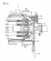
- FIGS. 1 to 5 illustrate an embodiment of the present disclosure.
- a connector 1 includes a vehicle-body mounting housing 2, a connector housing 10 fixed to the vehicle-body mounting housing 2, and a rear case 20 assembled to the back side of the connector housing 10.
- the vehicle-body mounting housing 2 includes a flange portion 3 and a cylindrical body 4 projecting forward from the center of the flange portion 3.
- the vehicle-body mounting housing 2 is fixed with bolts to a vehicle body (not illustrated) using holes 3a of the flange portion 3.
- the connector housing 10 includes a bottom wall portion 11 and a hood portion 12 erected from the bottom wall portion 11.
- the hood portion 12 is arranged in the cylindrical body 4 of the vehicle-body mounting housing 2 without a gap and is fixed to the cylindrical body 4.
- a connector fitting chamber 13 is formed surrounded by the hood portion 12 and the bottom wall portion 11.
- the connector fitting chamber 13 is open on the front side of the connector housing 10. For example, a mating connector (not illustrated) on the charging stand side is fitted to the connector fitting chamber 13.
- the bottom wall portion 11 is provided with, for example, ten terminal protection walls 15 and 16 projecting into the connector fitting chamber 13.
- Terminal insertion holes 15a and 16a into which mating terminals (not illustrated) are inserted, are formed at the distal end portions of the terminal protection walls 15 and 16, respectively.
- Two terminal protection walls 15 protect portions of power terminals 25 projecting to the connector fitting chamber 13 described below.
- Eight terminal protection walls 16 (four of which are illustrated in FIG. 2 ) protect portions of signal terminals 26 projecting into the connector fitting chamber 13 described below.
- the bottom wall portion 11 is provided with a water drainage passage 18 at the lowermost position of the connector fitting chamber 13 in the vehicle installation state.
- the water drainage passage 18 communicates the front side and the back side of the bottom wall portion 11.
- the rear case 20 is formed of a resin material.
- the rear case 20 is assembled so as to cover the entire back side of the connector housing 10.
- a packing 28 which is a first waterproof member, is interposed over the entire circumference. A space between the rear case 20 and the connector housing 10 is water-stopped by the packing 28.
- a drainage port 29 is formed at the lowermost position of the rear case 20.
- the drainage port 29 is open on the outer periphery of the rear case 20.
- a drain hose 30 is connected to the drainage port 29.
- the distal end of the drain hose 30 is, for example, led outside the vehicle.
- a cable opening 31 is provided at the uppermost position in the vehicle installation state. Cables W connected to the respective signal terminals 26 are respectively drawn out from the cable opening 31. A mat seal 32 is attached to the cable opening 31 in a compressed state. The cable opening 31 is waterproofed by the mat seal 32.
- the rear case 20 is provided with two terminal holding walls 21.
- the respective terminal holding walls 21 are arranged coaxially with the respective terminal protection walls 15 of the connector housing 10, and are in communication with the respective terminal insertion holes 15a.
- a pair of the terminal protection wall 15 and the terminal holding wall 21 coaxially arranged constitutes a terminal accommodating portion 14A.
- the two large-diameter terminal accommodating portions 14A are for the power terminals 25.
- the power terminals 25 each include a female contact portion 25a circumferentially arranged and a cable connection portion 25b crimped to the cable W.
- the signal terminals 26 each include a female contact portion arranged apart from each other and a cable connection portion connected to the cable W.
- Each terminal holding wall 21 of the large-diameter terminal accommodating portion 14A has an opening portion 20a on the back side of the rear case 20.
- Each terminal holding wall 21 extends from the front side to the back side of the rear case 20, and includes an accommodating chamber 21a having diameters in which the power terminal 25 is accommodated without a gap, a taper chamber 21b gradually expanding from the accommodating chamber 21a, and a large-diameter chamber 21c having diameters in which the power terminal 25 is inserted with a gap.
- the back surface end of the large-diameter chamber 21c is the opening portion 20a.
- the power terminal 25 is held (fixed) by a C-ring 22 on the terminal holding wall 21.
- An O-ring 23 which is a second waterproof member is attached to the outer periphery of the power terminal 25.
- the outer periphery of the power terminal 25 and the inner peripheral surface of the terminal holding wall 21 are waterproofed by the O-ring 23.
- the cable W connected to the power terminal 25 is waterproofed by a seal rubber 27 which is a third waterproof member interposed between the cable W and the inner peripheral surface of the terminal holding wall 21.
- the seal rubber 27 is held by a seal rubber holding member 40 attached to the outside of the back surface of the rear case 20.
- each of the small-diameter terminal protection walls 16 of the connector housing 10 is open in the rear case 20.
- a terminal locking member 24a and a cover 24b are mounted on the back side of each of the small-diameter terminal protection walls 16 opened in the rear case 20.
- a small-diameter terminal accommodating portion 14B is configured by each of the terminal protection walls 16, the terminal locking member 24a, and the cover 24b.
- the eight small-diameter terminal accommodating portions 14B are for the signal terminals 26.
- Each signal terminal 26 is held (fixed) by the terminal locking member 24a.
- a waterproof member is not interposed between the terminal protection wall 16, the terminal locking member 24a, and the cover 24b, and the signal terminal 26.
- a gap is formed between these members 16, 24a, 24b, 26 instead of a waterproof member. This gap constitutes a water drainage passage 19.
- the rear case 20 is assembled to the connector housing 10. After the rear case 20 is assembled, the power terminals 25 are assembled.
- the power terminals 25 are each connected to the cable W, and the C-ring 22 and the O-ring 23 are attached.
- the power terminals 25 are inserted from the opening portions 20a of the terminal holding walls 21 of the rear case 20.
- the C-ring 22 attached to the power terminal 25 is contracted when passing through the taper chamber 21b, and insertion is permitted.
- the C-ring 22 expands and enters a recess 21d (illustrated in FIG. 4 ) of the terminal holding wall 21.
- the power terminal 25 is positioned and fixed to the terminal accommodating portion 14A.
- the O-ring 23 attached to the outer periphery of the power terminal 25 is in close contact with the inner peripheral surface of the terminal holding wall 21 in a compressed state.
- the terminal accommodating portion 14A in which the power terminal 25 is accommodated is water-stopped.
- the water that has entered the terminal accommodating portion 14A from the side of the connector fitting chamber 13 is water-stopped at the position of the O-ring 23.
- the seal rubber 27 is in close contact with the outer periphery of the cable W and the inner peripheral surface of the terminal holding wall 21 in a compressed state.
- the terminal accommodating portion 14A in which the cable W is accommodated is water-stopped.
- the seal rubber 27 also prevents water entering the rear case 20 along the outer periphery of the cable W from the back side of the rear case 20.
- the connector 1 includes: the connector housing 10 including the connector fitting chamber 13 to which the mating connector is fitted, in which the power terminals 25 are arranged in a projecting state in the connector fitting chamber 13; the rear case 20 that covers the back side of the connector housing 10 opposite to the side on which the mating connector is fitted, and is assembled to the connector housing 10 through intermediation of the packing 28; the plurality of water drainage passages 18 and 19 provided in the connector housing 10, which allows water that has entered the side of the connector housing 10 on which the mating connector is fitted to flow into an inside of the rear case 20; the drainage port 29 provided in the rear case 20, which drains water inside the rear case 20 to the outside; the terminal accommodating portions 14A that hold the power terminals 25 in the projecting state in the connector fitting chamber 13 and has the opening portion 20a on the back side of the rear case 20; and the O-rings 23 each interposed between the inner peripheral surface of the terminal accommodating portion 14A on a side of the rear case 20 and the outer peripheral surface of the power terminal 25.
- the water which has entered the inside of the side of the connector housing 10 on which the mating connector is fitted enters the inside of the rear case 20 through the plurality of water drainage passages 18 and 19, and the water that has entered the inside of the rear case 20 is drained to the outside from the drainage port 29 of the rear case 20.
- the gap between the connector housing 10 and the rear case 20 is water-stopped by the packing 28, and the gap between the inside of the terminal holding wall 21 of the rear case 20 and the power terminal 25 is water-stopped by the O-ring 23.
- the water does not leak from those gaps to the outside of the rear case 20.
- the outside of the back side of the connector 1 can be prevented from getting wet with water.
- the power terminal 25 Since the power terminal 25 is accommodated in the terminal accommodating portion 14A from the opening portion 20a of the terminal accommodating portion 14A of the rear case 20 assembled to the connector housing 10, the power terminal 25 can be attached to the rear case 20 without causing the power terminal 25 to pass through the rear case 20 in advance. As described above, the back side of the connector 1 can be prevented from getting wet with water without deteriorating assembly workability.
- the drain hose 30 is connected to the drainage port 29. Therefore, water can be drained to a predetermined place by the drain hose 30.
- the terminal accommodating portion 14A includes the terminal protection wall 15 provided in the connector housing 10 and projecting to the connector fitting chamber 13, and the terminal holding wall 21 provided in the rear case 20 and holding the power terminal 25.
- the seal rubber 27 is interposed between the inner peripheral surface of the terminal holding wall 21 and the outer peripheral surface of the cable W connected to the power terminal 25.
- the O-ring 23 and the seal rubber 27 form a double water-stop structure, and water can be reliably prevented from leaking from the inside of the rear case 20 through the terminal holding wall 21 to the back side of the connector 1.
- the gap due to the bending of the cable W can be effectively prevented.
- the opening portion 20a is provided on the back side of the rear case 20 in the terminal accommodating portion 14A of the power terminal 25.
- the opening portion 20a may be provided on the back side of the rear case 20 also in the terminal accommodating portion 14B of the signal terminal 26.
- the terminal holding wall 21 of the terminal accommodating portion 14A of the power terminal 25 is provided in the rear case 20, but the terminal holding wall 21 may be provided across the connector housing 10 and the rear case 20.
Applications Claiming Priority (1)
| Application Number | Priority Date | Filing Date | Title |
|---|---|---|---|
| JP2018211348A JP6923500B2 (ja) | 2018-11-09 | 2018-11-09 | コネクタ |
Publications (2)
| Publication Number | Publication Date |
|---|---|
| EP3651283A1 EP3651283A1 (en) | 2020-05-13 |
| EP3651283B1 true EP3651283B1 (en) | 2024-01-03 |
Family
ID=68502988
Family Applications (1)
| Application Number | Title | Priority Date | Filing Date |
|---|---|---|---|
| EP19207834.3A Active EP3651283B1 (en) | 2018-11-09 | 2019-11-07 | Vehicle electrical connector |
Country Status (4)
| Country | Link |
|---|---|
| US (1) | US10985494B2 (ja) |
| EP (1) | EP3651283B1 (ja) |
| JP (1) | JP6923500B2 (ja) |
| CN (1) | CN111180930B (ja) |
Families Citing this family (7)
| Publication number | Priority date | Publication date | Assignee | Title |
|---|---|---|---|---|
| JP7156167B2 (ja) * | 2019-05-14 | 2022-10-19 | 住友電装株式会社 | コネクタ |
| CN111976513B (zh) * | 2020-08-22 | 2021-10-12 | 山东鹏耀智佳精密工业有限公司 | 一种新能源汽车充电枪 |
| CN112054352B (zh) * | 2020-08-31 | 2022-12-09 | 顺科新能源技术股份有限公司 | 集成面板 |
| JP7435511B2 (ja) * | 2021-03-15 | 2024-02-21 | 住友電装株式会社 | グロメットユニット及びワイヤハーネス |
| DE102022200056A1 (de) * | 2022-01-05 | 2023-07-06 | Robert Bosch Gesellschaft mit beschränkter Haftung | Steckverbindungseinrichtung |
| JP2023127151A (ja) * | 2022-03-01 | 2023-09-13 | 住友電装株式会社 | 電線付きコネクタ |
| WO2024012687A1 (de) | 2022-07-14 | 2024-01-18 | Pierburg Gmbh | Ladebuchse für eine ladevorrichtung für elektrisch antreibbare fahrzeuge |
Citations (1)
| Publication number | Priority date | Publication date | Assignee | Title |
|---|---|---|---|---|
| JP2013062055A (ja) * | 2011-09-12 | 2013-04-04 | Sumitomo Wiring Syst Ltd | 防水コネクタ |
Family Cites Families (16)
| Publication number | Priority date | Publication date | Assignee | Title |
|---|---|---|---|---|
| JP2005229740A (ja) * | 2004-02-13 | 2005-08-25 | Sumitomo Wiring Syst Ltd | 自動車用電気接続箱 |
| JP2008021467A (ja) * | 2006-07-11 | 2008-01-31 | Ngk Spark Plug Co Ltd | 防水コネクタ及びガスセンサユニット |
| US7465192B2 (en) * | 2006-09-11 | 2008-12-16 | J.S.T. Corporation | In-line sealed electrical connector apparatus |
| JP5312370B2 (ja) | 2010-02-23 | 2013-10-09 | トヨタ自動車株式会社 | インレット組立体 |
| JP5370778B2 (ja) * | 2010-05-24 | 2013-12-18 | 住友電装株式会社 | 車両側コネクタ |
| CN102263344B (zh) * | 2010-05-24 | 2013-06-05 | 凡甲电子(苏州)有限公司 | 插座电源连接器、插头电源连接器及其组件 |
| JP5679191B2 (ja) * | 2011-04-05 | 2015-03-04 | 住友電装株式会社 | 車両側コネクタ |
| JP5582093B2 (ja) * | 2011-05-17 | 2014-09-03 | 住友電装株式会社 | 車両側コネクタ |
| JP5939927B2 (ja) * | 2012-08-06 | 2016-06-22 | 矢崎総業株式会社 | 充電コネクタ |
| JP2015213029A (ja) * | 2014-05-07 | 2015-11-26 | 住友電装株式会社 | 防水コネクタ |
| JP6547678B2 (ja) | 2016-05-18 | 2019-07-24 | 住友電装株式会社 | 車両側コネクタ |
| JP6547679B2 (ja) | 2016-05-19 | 2019-07-24 | 住友電装株式会社 | 車両側コネクタ |
| JP6551300B2 (ja) * | 2016-05-19 | 2019-07-31 | 住友電装株式会社 | コネクタ |
| JP6561916B2 (ja) | 2016-05-27 | 2019-08-21 | 住友電装株式会社 | コネクタ |
| JP2018133278A (ja) * | 2017-02-17 | 2018-08-23 | 住友電装株式会社 | 充電インレット |
| CN107380094B (zh) * | 2017-06-30 | 2023-06-02 | 深圳市沃尔新能源电气科技股份有限公司 | 电连接器及新能源汽车 |
-
2018
- 2018-11-09 JP JP2018211348A patent/JP6923500B2/ja active Active
-
2019
- 2019-11-05 US US16/674,073 patent/US10985494B2/en active Active
- 2019-11-07 EP EP19207834.3A patent/EP3651283B1/en active Active
- 2019-11-08 CN CN201911088709.0A patent/CN111180930B/zh active Active
Patent Citations (1)
| Publication number | Priority date | Publication date | Assignee | Title |
|---|---|---|---|---|
| JP2013062055A (ja) * | 2011-09-12 | 2013-04-04 | Sumitomo Wiring Syst Ltd | 防水コネクタ |
Also Published As
| Publication number | Publication date |
|---|---|
| EP3651283A1 (en) | 2020-05-13 |
| JP2020077573A (ja) | 2020-05-21 |
| US10985494B2 (en) | 2021-04-20 |
| CN111180930A (zh) | 2020-05-19 |
| US20200153157A1 (en) | 2020-05-14 |
| CN111180930B (zh) | 2021-11-30 |
| JP6923500B2 (ja) | 2021-08-18 |
Similar Documents
| Publication | Publication Date | Title |
|---|---|---|
| EP3651283B1 (en) | Vehicle electrical connector | |
| KR101699576B1 (ko) | 전기 커넥터 조립체 | |
| EP2509169B1 (en) | Vehicle-side connector | |
| EP2525443B1 (en) | Vehicle-side connector and mounting method therefor | |
| EP2390959A1 (en) | Vehicle-side connector | |
| EP2475049B1 (en) | Connector | |
| EP3082201B1 (en) | Connector | |
| CN103094874A (zh) | 密封构件及其安装方法及设置有密封构件的充电连接器 | |
| EP2400600A1 (en) | Waterproof connector | |
| US6368130B1 (en) | Connector adapted to absorb a positional misalignment | |
| US10320115B2 (en) | Receptacle housing and receptacle | |
| US10594071B2 (en) | Charging inlet with a drainage port in a peripheral wall | |
| EP2839551B1 (en) | Jumper cable plug with moisture resistant seal | |
| CN105981234A (zh) | 连接器 | |
| JP4491294B2 (ja) | 機器用シールドコネクタ | |
| US20210194172A1 (en) | Connector | |
| JP2016201520A (ja) | 電子制御ユニットの防水構造 | |
| JP2019186022A (ja) | 防水カバー及びこれを備えた充電コネクタ | |
| WO2023166929A1 (ja) | 電線付きコネクタ | |
| JP4065164B2 (ja) | 電気コネクタの防水構造 | |
| JP2017191643A (ja) | 車両側コネクタ | |
| WO2022244465A1 (ja) | 端子台ユニット | |
| WO2021177225A1 (ja) | 端子モジュール | |
| WO2009008222A1 (en) | Packing and connector having the same | |
| JPH08236193A (ja) | 防水コネクタ |
Legal Events
| Date | Code | Title | Description |
|---|---|---|---|
| PUAI | Public reference made under article 153(3) epc to a published international application that has entered the european phase |
Free format text: ORIGINAL CODE: 0009012 |
|
| STAA | Information on the status of an ep patent application or granted ep patent |
Free format text: STATUS: REQUEST FOR EXAMINATION WAS MADE |
|
| 17P | Request for examination filed |
Effective date: 20191107 |
|
| AK | Designated contracting states |
Kind code of ref document: A1 Designated state(s): AL AT BE BG CH CY CZ DE DK EE ES FI FR GB GR HR HU IE IS IT LI LT LU LV MC MK MT NL NO PL PT RO RS SE SI SK SM TR |
|
| AX | Request for extension of the european patent |
Extension state: BA ME |
|
| RBV | Designated contracting states (corrected) |
Designated state(s): AL AT BE BG CH CY CZ DE DK EE ES FI FR GB GR HR HU IE IS IT LI LT LU LV MC MK MT NL NO PL PT RO RS SE SI SK SM TR |
|
| STAA | Information on the status of an ep patent application or granted ep patent |
Free format text: STATUS: EXAMINATION IS IN PROGRESS |
|
| 17Q | First examination report despatched |
Effective date: 20210304 |
|
| RAP3 | Party data changed (applicant data changed or rights of an application transferred) |
Owner name: YAZAKI CORPORATION |
|
| RIC1 | Information provided on ipc code assigned before grant |
Ipc: H01R 13/74 20060101ALN20230821BHEP Ipc: H01R 13/426 20060101ALN20230821BHEP Ipc: H01R 13/506 20060101ALI20230821BHEP Ipc: H01R 13/52 20060101AFI20230821BHEP |
|
| GRAP | Despatch of communication of intention to grant a patent |
Free format text: ORIGINAL CODE: EPIDOSNIGR1 |
|
| STAA | Information on the status of an ep patent application or granted ep patent |
Free format text: STATUS: GRANT OF PATENT IS INTENDED |
|
| RIC1 | Information provided on ipc code assigned before grant |
Ipc: H01R 13/74 20060101ALN20230908BHEP Ipc: H01R 13/426 20060101ALN20230908BHEP Ipc: H01R 13/506 20060101ALI20230908BHEP Ipc: H01R 13/52 20060101AFI20230908BHEP |
|
| INTG | Intention to grant announced |
Effective date: 20231004 |
|
| GRAS | Grant fee paid |
Free format text: ORIGINAL CODE: EPIDOSNIGR3 |
|
| GRAA | (expected) grant |
Free format text: ORIGINAL CODE: 0009210 |
|
| STAA | Information on the status of an ep patent application or granted ep patent |
Free format text: STATUS: THE PATENT HAS BEEN GRANTED |
|
| AK | Designated contracting states |
Kind code of ref document: B1 Designated state(s): AL AT BE BG CH CY CZ DE DK EE ES FI FR GB GR HR HU IE IS IT LI LT LU LV MC MK MT NL NO PL PT RO RS SE SI SK SM TR |
|
| REG | Reference to a national code |
Ref country code: GB Ref legal event code: FG4D |
|
| REG | Reference to a national code |
Ref country code: DE Ref legal event code: R096 Ref document number: 602019044364 Country of ref document: DE |
|
| REG | Reference to a national code |
Ref country code: CH Ref legal event code: EP |
|
| REG | Reference to a national code |
Ref country code: IE Ref legal event code: FG4D |
|
| REG | Reference to a national code |
Ref country code: LT Ref legal event code: MG9D |
|
| PG25 | Lapsed in a contracting state [announced via postgrant information from national office to epo] |
Ref country code: ES Free format text: LAPSE BECAUSE OF FAILURE TO SUBMIT A TRANSLATION OF THE DESCRIPTION OR TO PAY THE FEE WITHIN THE PRESCRIBED TIME-LIMIT Effective date: 20240103 |
|
| PG25 | Lapsed in a contracting state [announced via postgrant information from national office to epo] |
Ref country code: ES Free format text: LAPSE BECAUSE OF FAILURE TO SUBMIT A TRANSLATION OF THE DESCRIPTION OR TO PAY THE FEE WITHIN THE PRESCRIBED TIME-LIMIT Effective date: 20240103 |