EP3648450B1 - Appareil d'imagerie - Google Patents
Appareil d'imagerie Download PDFInfo
- Publication number
- EP3648450B1 EP3648450B1 EP19205835.2A EP19205835A EP3648450B1 EP 3648450 B1 EP3648450 B1 EP 3648450B1 EP 19205835 A EP19205835 A EP 19205835A EP 3648450 B1 EP3648450 B1 EP 3648450B1
- Authority
- EP
- European Patent Office
- Prior art keywords
- tilt
- area
- areas
- value
- tilt angle
- Prior art date
- Legal status (The legal status is an assumption and is not a legal conclusion. Google has not performed a legal analysis and makes no representation as to the accuracy of the status listed.)
- Active
Links
- 238000003384 imaging method Methods 0.000 title claims description 64
- 238000011156 evaluation Methods 0.000 claims description 134
- 230000003287 optical effect Effects 0.000 claims description 25
- 238000000034 method Methods 0.000 description 25
- 238000001514 detection method Methods 0.000 description 11
- 238000010586 diagram Methods 0.000 description 4
- 230000000694 effects Effects 0.000 description 2
- 238000004891 communication Methods 0.000 description 1
Images


Classifications
-
- H—ELECTRICITY
- H04—ELECTRIC COMMUNICATION TECHNIQUE
- H04N—PICTORIAL COMMUNICATION, e.g. TELEVISION
- H04N23/00—Cameras or camera modules comprising electronic image sensors; Control thereof
- H04N23/60—Control of cameras or camera modules
- H04N23/695—Control of camera direction for changing a field of view, e.g. pan, tilt or based on tracking of objects
-
- H—ELECTRICITY
- H04—ELECTRIC COMMUNICATION TECHNIQUE
- H04N—PICTORIAL COMMUNICATION, e.g. TELEVISION
- H04N23/00—Cameras or camera modules comprising electronic image sensors; Control thereof
- H04N23/58—Means for changing the camera field of view without moving the camera body, e.g. nutating or panning of optics or image sensors
-
- H—ELECTRICITY
- H04—ELECTRIC COMMUNICATION TECHNIQUE
- H04N—PICTORIAL COMMUNICATION, e.g. TELEVISION
- H04N23/00—Cameras or camera modules comprising electronic image sensors; Control thereof
- H04N23/60—Control of cameras or camera modules
- H04N23/67—Focus control based on electronic image sensor signals
-
- H—ELECTRICITY
- H04—ELECTRIC COMMUNICATION TECHNIQUE
- H04N—PICTORIAL COMMUNICATION, e.g. TELEVISION
- H04N17/00—Diagnosis, testing or measuring for television systems or their details
- H04N17/002—Diagnosis, testing or measuring for television systems or their details for television cameras
-
- H—ELECTRICITY
- H04—ELECTRIC COMMUNICATION TECHNIQUE
- H04N—PICTORIAL COMMUNICATION, e.g. TELEVISION
- H04N23/00—Cameras or camera modules comprising electronic image sensors; Control thereof
- H04N23/50—Constructional details
- H04N23/54—Mounting of pick-up tubes, electronic image sensors, deviation or focusing coils
-
- H—ELECTRICITY
- H04—ELECTRIC COMMUNICATION TECHNIQUE
- H04N—PICTORIAL COMMUNICATION, e.g. TELEVISION
- H04N23/00—Cameras or camera modules comprising electronic image sensors; Control thereof
- H04N23/60—Control of cameras or camera modules
- H04N23/67—Focus control based on electronic image sensor signals
- H04N23/673—Focus control based on electronic image sensor signals based on contrast or high frequency components of image signals, e.g. hill climbing method
-
- H—ELECTRICITY
- H04—ELECTRIC COMMUNICATION TECHNIQUE
- H04N—PICTORIAL COMMUNICATION, e.g. TELEVISION
- H04N23/00—Cameras or camera modules comprising electronic image sensors; Control thereof
- H04N23/60—Control of cameras or camera modules
- H04N23/67—Focus control based on electronic image sensor signals
- H04N23/675—Focus control based on electronic image sensor signals comprising setting of focusing regions
-
- H—ELECTRICITY
- H04—ELECTRIC COMMUNICATION TECHNIQUE
- H04N—PICTORIAL COMMUNICATION, e.g. TELEVISION
- H04N23/00—Cameras or camera modules comprising electronic image sensors; Control thereof
- H04N23/80—Camera processing pipelines; Components thereof
- H04N23/81—Camera processing pipelines; Components thereof for suppressing or minimising disturbance in the image signal generation
Definitions
- the present invention relates to an imaging apparatus configured to provide a tilt control.
- One conventional surveillance camera is installed at a high location, such as a ceiling, while its optical axis is directed obliquely downwardly to monitor a person passing on a road or to capture a car or its license plate (number plate). Since the optical axis of the camera is obliquely downwardly directed and a focal plane that is focused in imaging is orthogonal to the optical axis, the focal plane does not coincide with an imaging plane of an object to be actually captured. Hence, an in-focus area becomes part of the image, and the other area is out of focus.
- a tilt control One solution for this problem is a generally known technique called the Scheimpflug principle that expands the depth of field by tilting the optical system or the image sensor (referred to as a tilt control hereinafter).
- a position of an evaluation frame used to acquire the evaluation value in the captured image becomes important.
- the evaluation frame should be provided in an in-focus area in the tilt control, but the area suitable to obtain the evaluation value differs depending on the imaging scene. Hence, it is necessary for an automatic tilt control to detect the in-focus area in the tilt control and to determine the tilt angle based on the evaluation value acquired in the in-focus area.
- JP 11-242152 discloses an imaging apparatus that provides a tilt control using a tilt angle calculated based on focus information obtained in a plurality of predetermined areas in an imaging area.
- JP 2017-173802 discloses an imaging apparatus that provides a tilt control using a tilt angle calculated based on a focus shift amount of each of a plurality of focus detection areas.
- the imaging apparatus disclosed in JP 11-242152 prohibits the tilt control, if the mutual coincidence of the plurality of obtained tilt angles is lower than a predetermined value. Thus, even in an imaging scene in which a depth of an object becomes deeper due to the tilt imaging, the control may be prohibited depending on the area for acquiring the focus information.
- the user can individually specify a target to be focused among the plurality of focus detection areas, or the area is determined based on a mode selection for each preset group in a horizontal direction, a vertical direction, or a diagonal direction. Thus, the in-focus area cannot be specified without the user designation or the mode selection.
- a method for realizing tilt-shift photography and three-dimensional multi-area auto-focus via a touch screen operation comprising the following steps: A) utilizing a camera lens to acquire the image of a target, converting the image into an electrical signal via an image sensor, and displaying on a touch display screen; B) an operator selects a focus point via the touch screen; C) the camera lens automatically selects an offset direction, or the operator swipes on the touch screen to indicate the offset direction of the camera lens; D) conducting auto-focus on the Z axis; E) conducting auto-focus on the Rx axis and the Ry axis.
- An operation on a touch panel controls a camera lens to move according to a selected target area of interest, thus realizing three-dimensional auto-focus in areas with different depths of field selected by an operator on the touch screen, and realizing auto-focus of the target area of interest via selection on the touch screen.
- an electronic camera having a lens, an image pickup element for converting an object image formed on an image pickup surface into an electrical signal, a focus detection means for dividing the object image formed on the image pickup surface into a plurality of areas, and performing focus detection on the respective areas, a drive circuit for adjusting the lens on the basis of an output from the focus detection means, and a display circuit for displaying simultaneously focus detection information of the plurality of areas of the focus detection circuit on its display screen.
- an imaging apparatus which includes imaging means, display means for displaying an image acquired through the imaging means, means for calculating an AF evaluation value indicating a contrast from a signal inputted from an imaging part, means for dividing an image inputted from the imaging part and setting a multipoint contrast AF frame, and autofocus means for performing focusing control so as to focus on a position set from a multipoint frame.
- the imaging apparatus further includes means for performing focusing on the basis of the evaluation value of a latter AF frame, when an AF frame by which an evaluation value higher than the evaluation value of an AF frame including a closest subject in a depth is obtained is present.
- the present invention provides an imaging apparatus configured to provide a tilt control with a tilt angle suitable for an imaging scene.
- the present invention in its first aspect includes an imaging apparatus as specified in claims 1 to 13.
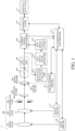
- FIG. 1 is a block diagram of an imaging apparatus 1 according to one embodiment of the present invention.
- An optical system 100 includes a zoom lens 101 that moves in an optical axis direction to change a focal length, a focus lens 102 that moves in the optical axis direction for focusing, and a diaphragm unit 103 that adjusts a light amount.
- the optical system 100 does not necessarily include the zoom lens 101, the focus lens 102, or the aperture unit 103, and may include another optical element.
- the light that has passed through the optical system 100 forms an object image as an optical image on an image sensor 106 via a band-pass filter (BPF hereinafter) 104 and a color filter 105.
- BPF band-pass filter
- the BPF 104 may be inserted into and ejected from the optical path of the optical system 100.
- the object image is photoelectrically converted by the image sensor 106.
- An analog electric signal (imaging signal) output from the image sensor 106 is gain-controlled by an AGC 107, converted into a digital signal by an A/D converter 108, and then input into a camera signal processor 109.
- the camera signal processor 109 performs various types of image processing for the digital imaging signal to generate an image signal.
- the image signal is output to a surveillance unit 111 connected to the imaging apparatus 1 via a communicator 110 by a wired or wireless communication.
- An evaluation value calculator 112 receives RGB pixel values or luminance values from the A/D converter 108 or the camera signal processor 109 for each evaluation frame set in the image, and calculates an evaluation value relating to a contrast at a specific frequency used for the tilt control and AF control.
- a tilt focal plane detector 113 detects an in-focus area (tilt focal plane hereinafter) in the tilt control based on the evaluation value of each evaluation frame calculated by the evaluation value calculator 112.
- a tilt angle calculator 114 calculates the tilt angle based on the evaluation value of the evaluation frame existing on the tilt focal plane detected by the tilt focal plane detector 113.
- a tilt/zoom/focus controller 115 controls an image sensor driver 116, a focus driver 117, and a zoom driver 118 based on an instruction from a communicator 110 corresponding to an external command and the tilt angle calculated by the tilt angle calculator 114. More specifically, a tilt angle set position, a focus set position, and a zoom set position are instructed to each of the image sensor driver 116, the focus driver 117, and the zoom driver 118.
- the image sensor driver 116 tilts the image sensor 106 around an image sensor rotational axis based on the tilt angle set position instructed from the tilt/zoom/focus controller 115.
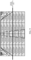
- This embodiment provides the image sensor rotational axis for tilting the image sensor 106 at the center of the image as illustrated in FIG. 9 .
- the focus driver 117 controls the position of the focus lens 102 based on the focus set position instructed from the tilt/zoom/focus controller 115.
- the zoom drive unit 118 controls the position of the zoom lens 101 based on the zoom set position instructed from the tilt/zoom/focus controller 115.
- the tilt control is a control that tilts the optical system 100 or the image sensor 106 and adjusts the tilt focal plane to a plane such as the ground.
- FIG. 2 explains the tilt control, and illustrates the tilted image sensor 106.
- the tilt control enables a short-distance object to a long-distance object to be located in a depth of field for a predetermined plane and maintains an in-focus state.
- a tilt angle b is calculated by the following expression (1) based on the Scheimpflug principle.
- the focal plane when the principal surface of the optical system and the imaging plane of the image sensor intersect with a single straight line, the focal plane also intersects on the same straight line.
- the evaluation frame for the tilt control may be set within a single plane area that is the tilt focus plane.
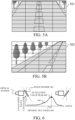
- FIGs. 3A and 3B illustrate two imaging scenes having different angles of view.
- a tilt focus plane 301-2 occupies a wide area, and an area excluding the left and right upper corners is suitable to obtain the evaluation value.
- a tilt focal plane 302-2 is about half of the focal plane 301-2, and if the evaluation value is acquired at the upper left portion, the tilt control cannot be performed well.
- the tilt focus plane thus differs depending on each imaging scene. In order to perform a tilt control according to the imaging scene, it is necessary to detect the tilt focus plane for each imaging scene, and to determine the tilt angle based on the evaluation value acquired on the detected tilt focus plane.
- detecting a tilt focal plane for each imaging scene There are multiple methods for detecting a tilt focal plane for each imaging scene. For example, one of them is to detect the tilt focal plane based on the evaluation value acquired for each of a plurality of areas on an image. This embodiment acquires the contrast as an evaluation value, and detects the tilt focal plane based on the acquired evaluation value. Then, a tilt angle suitable for the detected tilt focal plane is determined.
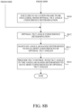
- FIG. 4 is a flowchart illustrating processing executed by the imaging apparatus 1.
- the tilt/zoom/focus controller 115 drives the focus lens 102 via the focus drive unit 117 to focus on the center of the image. Focusing may be performed by autofocusing (AF hereinafter) or manual focusing (MF hereinafter).
- the tilt/zoom/focus controller 115 sets a plurality of evaluation frames on the image.
- FIGs. 5A and 5B illustrate the evaluation frames set in the image.
- FIG. 5A illustrates an evaluation frame 501 set in the image 301-1 in FIG. 3A .
- FIG. 5B illustrates an evaluation frame 502 set in the image 302-1 in FIG. 3B .
- each captured image is divided into four rows and eight columns, but the division method is not limited to this example.
- the evaluation frame may be divided down to the pixel unit. In other words, each evaluation frame may include one or more pixels.
- FIG. 6 is a schematic diagram of the tilt scanning.
- the tilt scanning is a control for obtaining an evaluation value relating to the contrast for each evaluation frame set in the step S402 while changing the tilt angle of the image sensor 106.
- the evaluation value 601 is an evaluation value relating to the contrast obtained in a predetermined evaluation frame in a predetermined imaging scene.
- An evaluation value peak 602 is the maximum (or highest) value among the evaluation values 601. In the evaluation frame in which the evaluation value 601 is obtained, the tilt angle that provides the evaluation value peak 602 is an in-focus tilt angle (optimal tilt angle hereinafter) 603.
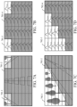
- FIGs. 7A to 7D illustrate the tilt focal plane detection result and the tilt scanning result for each evaluation frame.
- a tilt scanning result 701-3 in FIG. 7B is obtained when the tilt scanning is performed for an image 701-1 in FIG. 7A in each evaluation frame.
- a tilt scanning result 702-3 in FIG. 7D is obtained when the tilt scanning is performed for an image 702-1 in FIG. 7C in each evaluation frame.
- the same optimal tilt angle 603 is acquired in the evaluation frames on the tilt focus plane.
- the optimal tilt angle 603 different from that for the tilt focal plane area is acquired in an evaluation frame having a tall object.
- the tilt focal plane detector 113 maintains the optimal tilt angle 603 in each evaluation frame obtained in the step S403.
- the tilt focal plane detector 113 detects the tilt focal plane based on the optimal tilt angle 603 in each evaluation frame maintained in the step S404.
- the tilt focal plane detector 113 uses the fact that the optimal tilt angles coincide with each other on the same plane, and determines whether or not the optimal tilt angles in the respective evaluation frames coincide with each other (optimal tilt angle coincidence determination hereinafter).
- the area having the most coincidences of the optimal tilt angles is detected as the tilt focus plane.
- the result of performing the optimal tilt angle coincidence determination based on the tilt scanning result 701-3 in FIG. 7B is an evaluation frame 701-4 having the most coincidences of the optimal tilt angles.
- the optimal tilt angle coincidence determination enables only the evaluation frame that has the tilt focus plane to be detected. It is possible to remove an evaluation frame area having a tall object and thus an evaluation value unsuitable for the tilt angle calculation.
- the optimal tilt angle coincidence determination covers the perfect coincidence of the optimal tilt angle, but also the substantial coincidence in which the optimal tilt angle exists within a predetermined angular range.
- an angular range containing the most optimal tilt angles of the same type is obtained by the optimal tilt angle coincidence determination.
- the angular range may be determined based on the depth of focus calculated using at least one of the focal length, the object distance, the sensor size, the temperature, the humidity, and the light source.
- the tilt angle calculator 114 maintains the angular range having the most coincidences obtained in the step S405.
- the tilt/zoom/focus controller 115 performs the tilt control for driving the image sensor 106 so that the tilt angle is located within the angular range having the most coincidences maintained in the step S406.
- the tilt/zoom/focus controller 115 determines the tilt angle for the tilt control based on at least one of the minimum value, the maximum value, the average value of the optimal tilt angle included in the angular range having the most coincidences, and the optimal tilt angle having a large absolute value of the evaluation value peak. The value is determined based on at least one of the optimal tilt angles having a large value.
- the average value may be calculated based on the maximum value and the minimum value of the evaluation values obtained in each evaluation frame, and a weighted value such that an optima tilt angle of an evaluation frame with a larger difference can be more advantageous.
- the average value may be calculated by a weighted value based on the peak shape of the evaluation value acquired in each evaluation frame such that an optimal tilt angle of an evaluation frame having a steeper peak can be more advantageous.
- this embodiment acquires the tilt angle suitable for the tilt focal plane even in an imaging scene with a different composition by detecting the tilt focal plane and by determining the tilt angle used for tilt control. Therefore, the automatic tilt control suitable for the focal plane can be performed.
- the present invention tilts the image sensor 106, but the present invention is not limited to this embodiment.
- the effect of the present invention can also be obtained by tilting the optical system through a controller (not shown) configured to control the tilt of the optical system 100 or by tilting both the image sensor 106 and the optical system 100.
- This embodiment performs a tilt control while excluding an evaluation frame which has a difficulty in obtaining an accurate optimal tilt angle (or which yields an optimal tilt angle with a low reliability) and causes a noise in the optimal tilt angle coincidence determination.
- FIGs. 8A and 8B illustrate a flowchart illustrating processing executed by the imaging apparatus 1. A detailed description of the processing common to the flowchart in FIG. 4 in the first embodiment will be omitted.
- the tilt/zoom/focus controller 115 drives the focus lens 102 via the focus drive unit 117 to focus on the center of the image.
- the tilt/zoom/focus controller 115 sets a plurality of evaluation frames on the image.
- the evaluation value calculator 112 performs tilt scanning.
- the tilt focal plane detector 113 maintains the optimal tilt angle 603 in each evaluation frame obtained in the step S803.
- the tilt/zoom/focus controller 115 determines whether or not the evaluation frame set in the step S802 is an evaluation frame near the image sensor rotational axis. If the evaluation frame set in the step S802 is the evaluation frame near the image sensor rotational axis, the flow proceeds to the step S809. If the evaluation frame is not near the image sensor rotational axis, the flow proceeds to the step S806.
- FIG. 9 illustrates the image sensor rotational axis and evaluation frames on the image sensor 106.
- a change in the evaluation value is more significant by tilting the image sensor 106 as the area (evaluation frames 1-4 and 29-32) is more distant from the image sensor rotational axis.
- This embodiment excludes the evaluation frame determined to be close to the image sensor rotational axis from the target of the optimal tilt angle coincidence determination (the evaluation frame determined by the tilt focal plane detector 113).
- the tilt/zoom/focus controller 115 determines whether the evaluation frame set in the step S802 is an evaluation frame set in a low contrast area, based on the tilt scanning result acquired in the step S803. More specifically, the tilt/zoom/focus controller 115 determines whether or not a difference value between the maximum value and the minimum value of the evaluation value acquired in the step S803 is smaller than a predetermined value. When the difference value is smaller than the predetermined value, the flow proceeds to the step S809, and when larger than the predetermined value, the flow proceeds to the step S807. When the difference value is equal to the predetermined value, whichever can be arbitrarily set.
- the evaluation frame in which it is determined that the difference value between the maximum value and the minimum value of the evaluation value acquired in the step S803 is less than the predetermined value is excluded from the target of the optimal tilt angle coincidence determination.
- the tilt/zoom/focus controller 115 determines whether or not the evaluation frame set in the step S802 has a plurality of evaluation value peaks, based on the result of the tilt scanning acquired in the step S803. If the evaluation frame set in the step S802 has a plurality of evaluation value peaks, the flow proceeds to the step S809. If the evaluation frame does not have the plurality of evaluation value peaks or there is only one evaluation value peak, the flow proceeds to step S808.
- the tilt angle at which the evaluation value peak 602 is obtained may be different from the accurate optimal tilt angle 603 due to the influence of disturbance.
- the evaluation frames having a plurality of evaluation value peaks are excluded from the target of the optimal tilt angle coincidence determination.
- the tilt/zoom/focus controller 115 determines whether or not the evaluation frame set in the step S802 has an object whose luminance value is equal to or larger than a predetermined value, based on the image information obtained in each evaluation frame. If the evaluation frame set in the step S802 has the object with the luminance value equal to or larger than the predetermined value, the flow proceeds to the step S809, and if the evaluation frame does not have the object with the luminance value equal to or larger than the predetermined value, the flow proceeds to the step S812.
- a higher evaluation value may be obtained in a blurred state in the in-focus determination using the contrast for the evaluation value. If there is an object with a high luminance value such as a point light source in the evaluation frame, it is difficult to obtain an accurate optimal tilt angle in the step S804. Hence, the evaluation frame determined to have the object with the luminance value equal to or larger than the predetermined value is excluded from the target of the optimal tilt angle coincidence determination.
- the tilt/zoom/focus controller 115 determines whether or not there is a remaining evaluation frame not to be excluded in the step S805 to S808. If there is a remaining evaluation frame not to be excluded, the flow proceeds to the step S810, and if there is no remaining evaluation frame not to be excluded, the flow proceeds to step S811.
- the tilt/zoom/focus controller 115 excludes the evaluation frame to be excluded from the target of the optimal tilt angle coincidence determination in the step S812, which will be described later.
- the tilt/zoom/focus controller 115 changes settings of various types of predetermined values used for the step S S806 and S808.
- the predetermined values used for the steps S806 and S808 are set to be smaller than the predetermined value set last time.
- the tilt focal plane detector 113 performs the optimal tilt angle coincidence determination using the evaluation frames other than the evaluation frames excluded in the step S810.
- the tilt angle calculator 114 maintains the angular range having the most coincidences obtained in the step S812.
- the tilt/zoom/focus controller 115 performs the tilt control for driving the image sensor 106 such that the tilt angle is located within the angular range having the most coincidences maintained in the step S406.
- this embodiment performs the optimal tilt angle coincidence determination after excluding the evaluation frame that has difficulties in providing an accurate tilt angle, thereby obtaining a tilt angle suitable for the focal plane with higher accuracy.
- first and second embodiments discuss only one tilt focus plane in the imaging scene, in practice, there may be two or more areas detected as the tilt focus plane. However, where there are a plurality of areas detected as the tilt focal plane, all areas cannot be focused. This embodiment provides a control where there are a plurality of areas in the imaging scene that are detected as the focus plane.
- FIG. 10 illustrates an illustrative scene having two areas detected as the tilt focus plane.
- areas of a passage and an escalator correspond to the areas detected as the tilt focal plane.
- FIG. 11 illustrates two areas detected as the tilt focus plane as a result of performing the optimal tilt angle coincidence determination illustrated in the steps S405 and S812 in the first and second embodiments for the scene of FIG. 10 .
- Two areas 1101-1 and 1101-2 detected as the tilt focus plane correspond to the passage area and the escalator area, respectively, and both have the same optimal tilt angle corresponding to eight evaluation frames.
- this scene has a plurality of areas detected as the tilt focus plane.
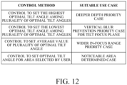
- FIG. 12 is a table that shows a correspondence between four control methods and use cases suitable for the control methods when there are a plurality of areas detected as the tilt focus plane.
- a first control method is a control to set the highest optimal tilt angle among a plurality of optimal tilt angles determined to coincide with each other by the same number of evaluation frames.
- the passage area 1101-1 can be focused in the illustrative scene in FIG. 10 through the control that sets the largest optimal tilt angle.
- the reason why the higher optimal tilt angle is used is that the control with the higher optimal tilt angle can provide a deeper depth than the control with the smaller optimal tilt angle, and thus a higher tilt control effect. Therefore, this control method is suitable for the imaging scene that always gives priority to a deeper depth.
- a second control method is a control to set the lowest optimal tilt angle among a plurality of optimal tilt angles determined to coincide with each other by the same number of evaluation frames.
- the escalator area 1101-2 can be focused in the illustrative scene in FIG. 10 .
- the reason why the lower optimal tilt angle is used is to suppress blurs caused by the tilt control in the direction vertical to the tilt focal plane.
- the focal plane and the blurring direction are always orthogonal to each other, and when the focal plane is a horizontal plane to the ground, the blurring direction is orthogonal to the ground. In other words, as the tilt angle is higher in the tilt control to make the tilt focal plane closer to the horizontal plane, the blur is increased for a vertically long object. Therefore, this control method is suitable for the imaging scene that gives priority to suppressing vertical blurs for the tilt focal plane, such as an imaging scene having a vertically long object.
- a third control method is a control to calculate an average value of a plurality of optimal tilt angles determined to coincide with each other by the same number of evaluation frames, and to set the calculated tilt angle.
- the calculation of the average value may use a value obtained by weighting the acquired optimal tilt angle.
- both the passage area 1101-1 and the escalator area 1101-2 can have properly increased depths.
- the first and second control methods may generate a large blur amount in an area that is not finally detected as a tilt focus plane among the areas detected as a tilt focus plane, whereas this control method can restrain a large blur amount in any area detected as the tilt focal plane. Therefore, this control method is suitable for an imaging scene that gives priority to a wider in-focus range.
- a fourth control method is a control that allows a user to select an area to be focused among a plurality of areas detected as the tilt focal plane, and sets the tilt angle of the selected area.
- a plurality of areas detected as the tilt focus plane are displayed on an image viewable by the user, and a UI is provided to enable the user to select one of the plurality of areas.
- the escalator area 1101-2 can be focused if the area that the user wants to view is the escalator area 1101-2.
- the first, second, and third control methods may not focus on the area intended by the user, whereas this control method guarantees focusing on the area intended by the user.
- this control method is suitable when the area that the user wants to view is determined.
- Which control method to follow among the above four control methods may be determined by user settings, or may be automatically determined by the imaging apparatus.
- this embodiment can provide a variety of tilt controls suitable for the use case, such as the deeper depth priority case, the case that gives priority to suppressing vertical blurs for the tilt focus plane, the wider in-focus range priority case, and the noticeable area determined case.
Claims (13)
- Appareil de formation d'image (1), comprenant :un capteur d'image (106) ;un système optique (100) ;une unité de commande (115) configuréepour modifier un angle d'inclinaison entre le capteur d'image (106) et un plan orthogonal à un axe optique du système optique (100) par une inclinaison d'au moins l'un du capteur d'image (106) et du système optique (100), etpour définir une pluralité de zones (501, 502) dans une image (301-1, 302-1, 701-1, 702-1) capturée par le capteur d'image (106) ;une unité d'acquisition de valeurs d'évaluation (112) configurée
pour acquérir, pour chaque zone (501, 502), une pluralité de valeurs d'évaluation de contraste de zone (601) par une modification de l'angle d'inclinaison par l'intermédiaire de l'unité de commande (115) ;une unité de détermination de zone d'évaluation (113) configuréepour acquérir, pour chaque zone de la pluralité de zones (501, 502), un angle d'inclinaison de zone optimal (603) correspondant à une valeur d'évaluation de contraste de zone maximale (602) dans la zone, etpour déterminer une zone d'évaluation (701-4, 702-4, 1101-1, 1101-2) comprenant le plus de zones ayant des angles d'inclinaison de zone optimaux coïncidents ; etune unité de détermination d'angle d'inclinaison (114) configurée pour déterminer un angle d'inclinaison cible sur la base des angles d'inclinaison de zone optimaux coïncidents de la zone d'évaluation (701-4, 702-4, 1101-1, 1101-2) ;dans lequel l'unité de commande (115) est en outre configurée pour modifier l'angle d'inclinaison sur la base de l'angle d'inclinaison cible. - Appareil de formation d'image selon la revendication 1, dans lequel chaque zone de la pluralité de zones (501, 502) comprend au moins un pixel.
- Appareil de formation d'image selon la revendication 1 ou 2, dans lequel l'unité de détermination de zone d'évaluation (113) est configurée
pour déterminer la zone d'évaluation (701-4, 702-4, 1101-1, 1101-2) comprenant le plus de zones ayant des angles d'inclinaison de zone optimaux (603) sur une plage angulaire prédéterminée. - Appareil de formation d'image selon la revendication 3, dans lequel la plage angulaire prédéterminée est déterminée sur la base d'une profondeur de mise au point calculée au moyen d'au moins l'une d'une distance focale, d'une distance objet, d'une taille du capteur d'image (106), d'une source de lumière, d'une température et d'une humidité.
- Appareil de formation d'image selon la revendication 3 ou 4, dans lequel l'unité de détermination d'angle d'inclinaison (114) est configurée pour déterminer l'angle d'inclinaison cible en tant qu'angle appartenant à la plage angulaire prédéterminée.
- Appareil de formation d'image selon la revendication 5, dans lequel l'unité de détermination d'angle d'inclinaison (114) est configurée pour calculer l'angle d'inclinaison cible sur la base d'au moins l'und'une valeur minimale des angles d'inclinaison de zone optimaux (603) compris dans la plage angulaire prédéterminée,d'une valeur maximale des angles d'inclinaison de zone optimaux (603) compris dans la plage angulaire prédéterminée,d'une valeur moyenne des angles d'inclinaison de zone optimaux (603) compris dans la plage angulaire prédéterminée, etd'angles d'inclinaison de zone optimaux (603) compris dans la plage angulaire prédéterminée et correspondant à des valeurs d'évaluation de contraste de zone maximales (602) ayant une valeur absolue supérieure à une valeur prédéterminée.
- Appareil de formation d'image selon la revendication 6, dans lequel la valeur moyenne des angles d'inclinaison de zone optimaux (603) est calculée sur la base de la valeur d'évaluation de contraste de zone maximale (602) et d'une valeur d'évaluation de contraste de zone minimale obtenues dans chaque zone de la pluralité de zones (501, 502) et d'une valeur pondérée.
- Appareil de formation d'image selon la revendication 7, dans lequel la valeur moyenne des angles d'inclinaison de zone optimaux (603) est calculée par une valeur pondérée sur la base d'une forme de pic des valeurs d'évaluation de contraste de zone (601) acquises dans chacune des zones de la pluralité de zones (501, 502).
- Appareil de formation d'image selon l'une quelconque des revendications 1 à 8, dans lequel l'unité de commande (115) est en outre configurée pour exclure, des zones de la pluralité de zones (501, 502) pour lesquelles ont été acquis des angles d'inclinaison de zone optimaux (603), des zones ayant des angles d'inclinaison optimaux (603) obtenus avec une fiabilité inférieure ou égale à une première fiabilité.
- Appareil de formation d'image selon la revendication 9, dans lequel l'unité de commande (115) est configurée pour déterminer des zones situées près d'un axe de rotation du capteur d'image (106), en tant que zones ayant les angles d'inclinaison de zone optimaux (603) obtenus avec la fiabilité inférieure ou égale à la première fiabilité.
- Appareil de formation d'image selon la revendication 9 ou 10, dans lequel l'unité de commande (115) est configurée pour déterminer des zones pour lesquelles une valeur de différence entre une valeur maximale et une valeur minimale des valeurs d'évaluation de contraste de zone (601) est inférieure à une valeur prédéterminée, en tant que zones ayant les angles d'inclinaison de zone optimaux (603) obtenus avec la fiabilité inférieure ou égale à la première fiabilité.
- Appareil de formation d'image selon l'une quelconque des revendications 9 à 11, dans lequel l'unité de commande (115) est configurée pour déterminer des zones ayant une pluralité de pics de valeur d'évaluation de contraste de zone (601), en tant que zones ayant les angles d'inclinaison de zone optimaux (603) obtenus avec la fiabilité inférieure ou égale à la première fiabilité.
- Appareil de formation d'image selon la revendication 9, dans lequel l'unité de commande (115) est configurée pour déterminer des zones comportant un objet ayant une valeur de luminance supérieure ou égale à une valeur prédéterminée, en tant que zones ayant les angles d'inclinaison de zone optimaux (603) obtenus avec la fiabilité inférieure ou égale à la première fiabilité.
Applications Claiming Priority (2)
| Application Number | Priority Date | Filing Date | Title |
|---|---|---|---|
| JP2018203640 | 2018-10-30 | ||
| JP2019173150A JP7383436B2 (ja) | 2018-10-30 | 2019-09-24 | 撮像装置 |
Publications (2)
| Publication Number | Publication Date |
|---|---|
| EP3648450A1 EP3648450A1 (fr) | 2020-05-06 |
| EP3648450B1 true EP3648450B1 (fr) | 2023-12-27 |
Family
ID=68387223
Family Applications (1)
| Application Number | Title | Priority Date | Filing Date |
|---|---|---|---|
| EP19205835.2A Active EP3648450B1 (fr) | 2018-10-30 | 2019-10-29 | Appareil d'imagerie |
Country Status (4)
| Country | Link |
|---|---|
| US (1) | US11343432B2 (fr) |
| EP (1) | EP3648450B1 (fr) |
| KR (1) | KR102510704B1 (fr) |
| CN (1) | CN111200706B (fr) |
Families Citing this family (11)
| Publication number | Priority date | Publication date | Assignee | Title |
|---|---|---|---|---|
| KR102510704B1 (ko) * | 2018-10-30 | 2023-03-16 | 캐논 가부시끼가이샤 | 촬상 장치 |
| JP7271159B2 (ja) * | 2018-12-14 | 2023-05-11 | キヤノン株式会社 | 制御装置、撮像装置、レンズ装置、プログラム、および制御装置の制御方法 |
| US11381731B2 (en) | 2019-03-15 | 2022-07-05 | Canon Kabushiki Kaisha | Imaging apparatus, imaging control method, and storage medium |
| JP7305485B2 (ja) | 2019-08-29 | 2023-07-10 | キヤノン株式会社 | 制御装置、撮像装置、レンズ装置、制御方法、および、プログラム |
| JP7362360B2 (ja) | 2019-08-29 | 2023-10-17 | キヤノン株式会社 | 制御装置、撮像装置、レンズ装置、および、プログラム |
| JP7471799B2 (ja) * | 2019-11-12 | 2024-04-22 | キヤノン株式会社 | 制御装置、撮像装置、制御方法、および、プログラム |
| CN112055155B (zh) * | 2020-09-10 | 2022-03-11 | 中科微至智能制造科技江苏股份有限公司 | 基于自学习式的工业相机自动调焦方法、装置及系统 |
| EP3968624B1 (fr) * | 2020-09-14 | 2023-11-15 | Canon Kabushiki Kaisha | Appareil de traitement d'informations, procédé de traitement d'informations et programme |
| JP2022128941A (ja) * | 2021-02-24 | 2022-09-05 | キヤノン株式会社 | 撮像装置、コンピュータプログラム、記憶媒体及び撮像装置の制御方法 |
| JP2022166384A (ja) * | 2021-04-21 | 2022-11-02 | キヤノン株式会社 | 制御装置、撮像装置、制御方法、およびプログラム |
| US11722775B2 (en) * | 2021-08-17 | 2023-08-08 | Canon Kabushiki Kaisha | Image pickup apparatus and controlling method thereof |
Family Cites Families (49)
| Publication number | Priority date | Publication date | Assignee | Title |
|---|---|---|---|---|
| US5453784A (en) * | 1993-02-10 | 1995-09-26 | Krishnan; Arun | Imaging apparatus and method for determining range and determining focus information |
| US5432331A (en) * | 1994-06-07 | 1995-07-11 | Eastman Kodak Company | Method and apparatus for detecting focus of moving images with tilted plane detector and time delay means |
| JPH08186757A (ja) * | 1994-12-28 | 1996-07-16 | Canon Inc | 電子カメラ |
| DE19637629A1 (de) * | 1996-09-16 | 1998-03-19 | Eastman Kodak Co | Elektronische Kamera zur Realisierung der Abbildungseigenschaften einer Studio-Balgenkamera |
| JP3733228B2 (ja) * | 1997-12-25 | 2006-01-11 | キヤノン株式会社 | アオリ機構付き撮像装置、方法、及び記憶媒体 |
| US6023056A (en) * | 1998-05-04 | 2000-02-08 | Eastman Kodak Company | Scene-based autofocus method |
| DE69820871T2 (de) * | 1998-07-08 | 2004-12-16 | Hewlett-Packard Co. (N.D.Ges.D.Staates Delaware), Palo Alto | Kamera mit Vorrichtung zur Korrektur des Trapezoidalbildfehlers |
| JP3207166B2 (ja) | 1998-12-09 | 2001-09-10 | オリンパス光学工業株式会社 | 撮像装置 |
| JP4297630B2 (ja) * | 2001-04-25 | 2009-07-15 | 株式会社リコー | 電子撮像装置 |
| DE10359193A1 (de) * | 2003-12-17 | 2005-07-28 | Hella Kgaa Hueck & Co. | Kameraanordnung und Verfahren zur Justierung einer Kameraanordnung |
| US7183530B2 (en) * | 2004-01-07 | 2007-02-27 | Pentax Corporation | Imaging device and electronic apparatus with the same |
| JP4007986B2 (ja) * | 2004-09-21 | 2007-11-14 | オリンパス株式会社 | 撮像装置 |
| US20060082657A1 (en) * | 2004-10-19 | 2006-04-20 | Raymond Meier | Digital camera improvements |
| DE102005041431B4 (de) * | 2005-08-31 | 2011-04-28 | WÖHLER, Christian | Digitale Kamera mit verschwenkbarem Bildsensor |
| JP4944498B2 (ja) * | 2006-05-26 | 2012-05-30 | キヤノン株式会社 | 撮像光学系 |
| JP2008205569A (ja) * | 2007-02-16 | 2008-09-04 | Fujifilm Corp | 撮像装置及び方法 |
| JP2008309998A (ja) * | 2007-06-14 | 2008-12-25 | Sony Corp | ティルトレンズ系及び撮像装置 |
| JP2009124314A (ja) * | 2007-11-13 | 2009-06-04 | Nikon Corp | カメラ、および画像処理プログラム |
| WO2009155926A1 (fr) | 2008-06-27 | 2009-12-30 | Hasselblad A/S | Adaptateur d’inclinaison et de décalage, caméra et procédé de correction d’images |
| GB2482290A (en) * | 2010-07-26 | 2012-02-01 | St Microelectronics Res & Dev | Autofocus method using tilted focal plane |
| JP2012128021A (ja) * | 2010-12-13 | 2012-07-05 | Canon Inc | 焦点調節装置、撮像装置、及び制御方法 |
| CN103782214A (zh) * | 2011-09-13 | 2014-05-07 | 株式会社日立制作所 | 摄像装置 |
| US9366839B2 (en) * | 2012-11-01 | 2016-06-14 | Sharp Kabushiki Kaisha | Position adjustment device and position adjustment method |
| CN103246131B (zh) * | 2013-05-20 | 2016-06-01 | 爱佩仪光电技术(深圳)有限公司 | 利用可控制镜头倾斜的对焦马达实现3维多区自动对焦的方法 |
| JP6415140B2 (ja) * | 2014-07-04 | 2018-10-31 | キヤノン株式会社 | 撮像装置及びその制御方法 |
| JP2016080738A (ja) | 2014-10-10 | 2016-05-16 | キヤノン株式会社 | 撮像装置、自動合焦方法 |
| CN104853105B (zh) | 2015-06-15 | 2019-04-23 | 爱佩仪光电技术有限公司 | 基于可控制镜头倾斜的摄像装置的三维快速自动对焦方法 |
| CN104902190A (zh) * | 2015-06-24 | 2015-09-09 | 联想(北京)有限公司 | 控制方法、摄像装置及电子设备 |
| JP6788348B2 (ja) * | 2016-01-06 | 2020-11-25 | キヤノン株式会社 | 光学制御装置、光学機器、コンピュータープログラムおよび制御方法 |
| JP2017146328A (ja) * | 2016-02-15 | 2017-08-24 | キヤノン株式会社 | 撮像装置 |
| US10341567B2 (en) * | 2016-03-16 | 2019-07-02 | Ricoh Imaging Company, Ltd. | Photographing apparatus |
| JP6838417B2 (ja) | 2016-03-16 | 2021-03-03 | リコーイメージング株式会社 | 撮影装置 |
| JP6685845B2 (ja) * | 2016-06-09 | 2020-04-22 | キヤノン株式会社 | 撮像装置および撮像プログラム |
| JP7034705B2 (ja) * | 2017-12-22 | 2022-03-14 | キヤノン株式会社 | レンズ装置、撮像装置及びカメラシステム |
| JP7289621B2 (ja) * | 2018-09-21 | 2023-06-12 | キヤノン株式会社 | 制御装置、撮像装置、制御方法、および、プログラム |
| JP7191639B2 (ja) * | 2018-10-22 | 2022-12-19 | キヤノン株式会社 | 制御装置、撮像装置、制御方法、および、プログラム |
| JP7271132B2 (ja) * | 2018-10-26 | 2023-05-11 | キヤノン株式会社 | 撮像装置および監視システム |
| KR102510704B1 (ko) * | 2018-10-30 | 2023-03-16 | 캐논 가부시끼가이샤 | 촬상 장치 |
| JP7204449B2 (ja) * | 2018-11-29 | 2023-01-16 | キヤノン株式会社 | 制御装置、撮像装置、制御方法およびプログラム |
| JP7210246B2 (ja) * | 2018-11-30 | 2023-01-23 | キヤノン株式会社 | 撮像装置、撮像装置の制御方法、情報処理装置、撮像システム、プログラム、および、記憶媒体 |
| JP2020092338A (ja) * | 2018-12-06 | 2020-06-11 | キヤノン株式会社 | 撮像制御装置およびその制御方法 |
| JP7271159B2 (ja) * | 2018-12-14 | 2023-05-11 | キヤノン株式会社 | 制御装置、撮像装置、レンズ装置、プログラム、および制御装置の制御方法 |
| JP7262997B2 (ja) * | 2018-12-27 | 2023-04-24 | キヤノン株式会社 | 制御装置、撮像装置、および、プログラム |
| EP3684046B1 (fr) * | 2019-01-17 | 2022-12-07 | Canon Kabushiki Kaisha | Mise au point automatique dans un dispositif de capture d'images utilisant le principe scheimpflug |
| JP7271220B2 (ja) * | 2019-02-26 | 2023-05-11 | キヤノン株式会社 | 撮像装置、撮像装置の制御方法、プログラム、および、記憶媒体 |
| US11381731B2 (en) * | 2019-03-15 | 2022-07-05 | Canon Kabushiki Kaisha | Imaging apparatus, imaging control method, and storage medium |
| JP7327964B2 (ja) * | 2019-03-20 | 2023-08-16 | キヤノン株式会社 | 制御装置、撮像システム、プログラム、および、記憶媒体 |
| JP7362360B2 (ja) * | 2019-08-29 | 2023-10-17 | キヤノン株式会社 | 制御装置、撮像装置、レンズ装置、および、プログラム |
| JP7305485B2 (ja) * | 2019-08-29 | 2023-07-10 | キヤノン株式会社 | 制御装置、撮像装置、レンズ装置、制御方法、および、プログラム |
-
2019
- 2019-10-24 KR KR1020190132774A patent/KR102510704B1/ko active IP Right Grant
- 2019-10-29 US US16/666,460 patent/US11343432B2/en active Active
- 2019-10-29 EP EP19205835.2A patent/EP3648450B1/fr active Active
- 2019-10-30 CN CN201911043678.7A patent/CN111200706B/zh active Active
Also Published As
| Publication number | Publication date |
|---|---|
| EP3648450A1 (fr) | 2020-05-06 |
| US11343432B2 (en) | 2022-05-24 |
| KR20200049582A (ko) | 2020-05-08 |
| CN111200706A (zh) | 2020-05-26 |
| CN111200706B (zh) | 2021-12-28 |
| KR102510704B1 (ko) | 2023-03-16 |
| US20200137313A1 (en) | 2020-04-30 |
Similar Documents
| Publication | Publication Date | Title |
|---|---|---|
| EP3648450B1 (fr) | Appareil d'imagerie | |
| EP3722871B1 (fr) | Appareil d'imagerie, procédé de commande d'imagerie et support d'enregistrement | |
| CN111447358B (zh) | 摄像设备 | |
| EP3667409B1 (fr) | Appareil de commande, appareil d'imagerie et logiciel | |
| CN112449107B (zh) | 控制设备、控制方法和存储介质 | |
| US11582394B2 (en) | Control apparatus, control method, and storage medium for providing tilt control | |
| JP7336330B2 (ja) | 制御装置、撮像装置、制御方法、および、プログラム | |
| JP5896763B2 (ja) | 光学機器および自動焦点調節を行う方法 | |
| CN111614890B (zh) | 摄像设备、摄像设备的控制方法和存储介质 | |
| JP7433848B2 (ja) | 撮像装置、コンピュータプログラム、記憶媒体および撮像制御方法 | |
| JP7383436B2 (ja) | 撮像装置 | |
| JP2007133301A (ja) | オートフォーカスカメラ | |
| JP2021113909A (ja) | 制御装置、撮像装置、監視カメラシステム、制御方法、および、プログラム | |
| JP2009092747A (ja) | 撮像装置、および撮像方法 | |
| US20200007780A1 (en) | Apparatus and method | |
| JP7463078B2 (ja) | 撮像装置 | |
| JP2022128941A (ja) | 撮像装置、コンピュータプログラム、記憶媒体及び撮像装置の制御方法 | |
| JP2021019214A (ja) | 撮像装置、コンピュータプログラムおよび記憶媒体 | |
| JPH07283996A (ja) | 撮像装置 |
Legal Events
| Date | Code | Title | Description |
|---|---|---|---|
| PUAI | Public reference made under article 153(3) epc to a published international application that has entered the european phase |
Free format text: ORIGINAL CODE: 0009012 |
|
| STAA | Information on the status of an ep patent application or granted ep patent |
Free format text: STATUS: THE APPLICATION HAS BEEN PUBLISHED |
|
| AK | Designated contracting states |
Kind code of ref document: A1 Designated state(s): AL AT BE BG CH CY CZ DE DK EE ES FI FR GB GR HR HU IE IS IT LI LT LU LV MC MK MT NL NO PL PT RO RS SE SI SK SM TR |
|
| AX | Request for extension of the european patent |
Extension state: BA ME |
|
| STAA | Information on the status of an ep patent application or granted ep patent |
Free format text: STATUS: REQUEST FOR EXAMINATION WAS MADE |
|
| 17P | Request for examination filed |
Effective date: 20201106 |
|
| RBV | Designated contracting states (corrected) |
Designated state(s): AL AT BE BG CH CY CZ DE DK EE ES FI FR GB GR HR HU IE IS IT LI LT LU LV MC MK MT NL NO PL PT RO RS SE SI SK SM TR |
|
| STAA | Information on the status of an ep patent application or granted ep patent |
Free format text: STATUS: EXAMINATION IS IN PROGRESS |
|
| 17Q | First examination report despatched |
Effective date: 20211214 |
|
| REG | Reference to a national code |
Ref country code: DE Ref legal event code: R079 Ref document number: 602019043916 Country of ref document: DE Free format text: PREVIOUS MAIN CLASS: H04N0005232000 Ipc: H04N0023580000 Ref country code: DE Free format text: PREVIOUS MAIN CLASS: H04N0005232000 Ipc: H04N0023580000 |
|
| GRAP | Despatch of communication of intention to grant a patent |
Free format text: ORIGINAL CODE: EPIDOSNIGR1 |
|
| RIC1 | Information provided on ipc code assigned before grant |
Ipc: H04N 23/67 20230101ALI20230606BHEP Ipc: H04N 23/58 20230101AFI20230606BHEP |
|
| STAA | Information on the status of an ep patent application or granted ep patent |
Free format text: STATUS: GRANT OF PATENT IS INTENDED |
|
| INTG | Intention to grant announced |
Effective date: 20230713 |
|
| GRAS | Grant fee paid |
Free format text: ORIGINAL CODE: EPIDOSNIGR3 |
|
| GRAA | (expected) grant |
Free format text: ORIGINAL CODE: 0009210 |
|
| STAA | Information on the status of an ep patent application or granted ep patent |
Free format text: STATUS: THE PATENT HAS BEEN GRANTED |
|
| AK | Designated contracting states |
Kind code of ref document: B1 Designated state(s): AL AT BE BG CH CY CZ DE DK EE ES FI FR GB GR HR HU IE IS IT LI LT LU LV MC MK MT NL NO PL PT RO RS SE SI SK SM TR |
|
| REG | Reference to a national code |
Ref country code: GB Ref legal event code: FG4D |
|
| REG | Reference to a national code |
Ref country code: CH Ref legal event code: EP |
|
| REG | Reference to a national code |
Ref country code: DE Ref legal event code: R096 Ref document number: 602019043916 Country of ref document: DE |
|
| REG | Reference to a national code |
Ref country code: IE Ref legal event code: FG4D |
|
| PG25 | Lapsed in a contracting state [announced via postgrant information from national office to epo] |
Ref country code: GR Free format text: LAPSE BECAUSE OF FAILURE TO SUBMIT A TRANSLATION OF THE DESCRIPTION OR TO PAY THE FEE WITHIN THE PRESCRIBED TIME-LIMIT Effective date: 20240328 |
|
| REG | Reference to a national code |
Ref country code: LT Ref legal event code: MG9D |
|
| PG25 | Lapsed in a contracting state [announced via postgrant information from national office to epo] |
Ref country code: LT Free format text: LAPSE BECAUSE OF FAILURE TO SUBMIT A TRANSLATION OF THE DESCRIPTION OR TO PAY THE FEE WITHIN THE PRESCRIBED TIME-LIMIT Effective date: 20231227 |
|
| PG25 | Lapsed in a contracting state [announced via postgrant information from national office to epo] |
Ref country code: ES Free format text: LAPSE BECAUSE OF FAILURE TO SUBMIT A TRANSLATION OF THE DESCRIPTION OR TO PAY THE FEE WITHIN THE PRESCRIBED TIME-LIMIT Effective date: 20231227 |
|
| PG25 | Lapsed in a contracting state [announced via postgrant information from national office to epo] |
Ref country code: LT Free format text: LAPSE BECAUSE OF FAILURE TO SUBMIT A TRANSLATION OF THE DESCRIPTION OR TO PAY THE FEE WITHIN THE PRESCRIBED TIME-LIMIT Effective date: 20231227 Ref country code: GR Free format text: LAPSE BECAUSE OF FAILURE TO SUBMIT A TRANSLATION OF THE DESCRIPTION OR TO PAY THE FEE WITHIN THE PRESCRIBED TIME-LIMIT Effective date: 20240328 Ref country code: FI Free format text: LAPSE BECAUSE OF FAILURE TO SUBMIT A TRANSLATION OF THE DESCRIPTION OR TO PAY THE FEE WITHIN THE PRESCRIBED TIME-LIMIT Effective date: 20231227 Ref country code: ES Free format text: LAPSE BECAUSE OF FAILURE TO SUBMIT A TRANSLATION OF THE DESCRIPTION OR TO PAY THE FEE WITHIN THE PRESCRIBED TIME-LIMIT Effective date: 20231227 Ref country code: BG Free format text: LAPSE BECAUSE OF FAILURE TO SUBMIT A TRANSLATION OF THE DESCRIPTION OR TO PAY THE FEE WITHIN THE PRESCRIBED TIME-LIMIT Effective date: 20240327 |
|
| REG | Reference to a national code |
Ref country code: NL Ref legal event code: MP Effective date: 20231227 |