EP3636356B1 - Substrate cleaning member and substrate cleaning apparatus - Google Patents
Substrate cleaning member and substrate cleaning apparatus Download PDFInfo
- Publication number
- EP3636356B1 EP3636356B1 EP19202831.4A EP19202831A EP3636356B1 EP 3636356 B1 EP3636356 B1 EP 3636356B1 EP 19202831 A EP19202831 A EP 19202831A EP 3636356 B1 EP3636356 B1 EP 3636356B1
- Authority
- EP
- European Patent Office
- Prior art keywords
- substrate
- cleaning member
- cleaning
- roll type
- diameter portions
- Prior art date
- Legal status (The legal status is an assumption and is not a legal conclusion. Google has not performed a legal analysis and makes no representation as to the accuracy of the status listed.)
- Active
Links
Images


Classifications
-
- H—ELECTRICITY
- H01—ELECTRIC ELEMENTS
- H01L—SEMICONDUCTOR DEVICES NOT COVERED BY CLASS H10
- H01L21/00—Processes or apparatus adapted for the manufacture or treatment of semiconductor or solid state devices or of parts thereof
- H01L21/67—Apparatus specially adapted for handling semiconductor or electric solid state devices during manufacture or treatment thereof; Apparatus specially adapted for handling wafers during manufacture or treatment of semiconductor or electric solid state devices or components ; Apparatus not specifically provided for elsewhere
- H01L21/67005—Apparatus not specifically provided for elsewhere
- H01L21/67011—Apparatus for manufacture or treatment
- H01L21/67017—Apparatus for fluid treatment
- H01L21/67028—Apparatus for fluid treatment for cleaning followed by drying, rinsing, stripping, blasting or the like
- H01L21/6704—Apparatus for fluid treatment for cleaning followed by drying, rinsing, stripping, blasting or the like for wet cleaning or washing
- H01L21/67046—Apparatus for fluid treatment for cleaning followed by drying, rinsing, stripping, blasting or the like for wet cleaning or washing using mainly scrubbing means, e.g. brushes
-
- B—PERFORMING OPERATIONS; TRANSPORTING
- B08—CLEANING
- B08B—CLEANING IN GENERAL; PREVENTION OF FOULING IN GENERAL
- B08B1/00—Cleaning by methods involving the use of tools
- B08B1/10—Cleaning by methods involving the use of tools characterised by the type of cleaning tool
- B08B1/14—Wipes; Absorbent members, e.g. swabs or sponges
- B08B1/143—Wipes
-
- B—PERFORMING OPERATIONS; TRANSPORTING
- B08—CLEANING
- B08B—CLEANING IN GENERAL; PREVENTION OF FOULING IN GENERAL
- B08B1/00—Cleaning by methods involving the use of tools
- B08B1/20—Cleaning of moving articles, e.g. of moving webs or of objects on a conveyor
-
- B—PERFORMING OPERATIONS; TRANSPORTING
- B08—CLEANING
- B08B—CLEANING IN GENERAL; PREVENTION OF FOULING IN GENERAL
- B08B1/00—Cleaning by methods involving the use of tools
- B08B1/30—Cleaning by methods involving the use of tools by movement of cleaning members over a surface
- B08B1/32—Cleaning by methods involving the use of tools by movement of cleaning members over a surface using rotary cleaning members
- B08B1/34—Cleaning by methods involving the use of tools by movement of cleaning members over a surface using rotary cleaning members rotating about an axis parallel to the surface
-
- H—ELECTRICITY
- H01—ELECTRIC ELEMENTS
- H01L—SEMICONDUCTOR DEVICES NOT COVERED BY CLASS H10
- H01L21/00—Processes or apparatus adapted for the manufacture or treatment of semiconductor or solid state devices or of parts thereof
- H01L21/02—Manufacture or treatment of semiconductor devices or of parts thereof
- H01L21/02041—Cleaning
- H01L21/02043—Cleaning before device manufacture, i.e. Begin-Of-Line process
- H01L21/02052—Wet cleaning only
-
- H—ELECTRICITY
- H01—ELECTRIC ELEMENTS
- H01L—SEMICONDUCTOR DEVICES NOT COVERED BY CLASS H10
- H01L21/00—Processes or apparatus adapted for the manufacture or treatment of semiconductor or solid state devices or of parts thereof
- H01L21/02—Manufacture or treatment of semiconductor devices or of parts thereof
- H01L21/02041—Cleaning
- H01L21/02096—Cleaning only mechanical cleaning
-
- H—ELECTRICITY
- H01—ELECTRIC ELEMENTS
- H01L—SEMICONDUCTOR DEVICES NOT COVERED BY CLASS H10
- H01L21/00—Processes or apparatus adapted for the manufacture or treatment of semiconductor or solid state devices or of parts thereof
- H01L21/67—Apparatus specially adapted for handling semiconductor or electric solid state devices during manufacture or treatment thereof; Apparatus specially adapted for handling wafers during manufacture or treatment of semiconductor or electric solid state devices or components ; Apparatus not specifically provided for elsewhere
- H01L21/67005—Apparatus not specifically provided for elsewhere
- H01L21/67011—Apparatus for manufacture or treatment
- H01L21/67017—Apparatus for fluid treatment
- H01L21/67028—Apparatus for fluid treatment for cleaning followed by drying, rinsing, stripping, blasting or the like
- H01L21/6704—Apparatus for fluid treatment for cleaning followed by drying, rinsing, stripping, blasting or the like for wet cleaning or washing
- H01L21/67051—Apparatus for fluid treatment for cleaning followed by drying, rinsing, stripping, blasting or the like for wet cleaning or washing using mainly spraying means, e.g. nozzles
-
- H—ELECTRICITY
- H01—ELECTRIC ELEMENTS
- H01L—SEMICONDUCTOR DEVICES NOT COVERED BY CLASS H10
- H01L21/00—Processes or apparatus adapted for the manufacture or treatment of semiconductor or solid state devices or of parts thereof
- H01L21/67—Apparatus specially adapted for handling semiconductor or electric solid state devices during manufacture or treatment thereof; Apparatus specially adapted for handling wafers during manufacture or treatment of semiconductor or electric solid state devices or components ; Apparatus not specifically provided for elsewhere
- H01L21/683—Apparatus specially adapted for handling semiconductor or electric solid state devices during manufacture or treatment thereof; Apparatus specially adapted for handling wafers during manufacture or treatment of semiconductor or electric solid state devices or components ; Apparatus not specifically provided for elsewhere for supporting or gripping
- H01L21/687—Apparatus specially adapted for handling semiconductor or electric solid state devices during manufacture or treatment thereof; Apparatus specially adapted for handling wafers during manufacture or treatment of semiconductor or electric solid state devices or components ; Apparatus not specifically provided for elsewhere for supporting or gripping using mechanical means, e.g. chucks, clamps or pinches
- H01L21/68714—Apparatus specially adapted for handling semiconductor or electric solid state devices during manufacture or treatment thereof; Apparatus specially adapted for handling wafers during manufacture or treatment of semiconductor or electric solid state devices or components ; Apparatus not specifically provided for elsewhere for supporting or gripping using mechanical means, e.g. chucks, clamps or pinches the wafers being placed on a susceptor, stage or support
- H01L21/68764—Apparatus specially adapted for handling semiconductor or electric solid state devices during manufacture or treatment thereof; Apparatus specially adapted for handling wafers during manufacture or treatment of semiconductor or electric solid state devices or components ; Apparatus not specifically provided for elsewhere for supporting or gripping using mechanical means, e.g. chucks, clamps or pinches the wafers being placed on a susceptor, stage or support characterised by a movable susceptor, stage or support, others than those only rotating on their own vertical axis, e.g. susceptors on a rotating caroussel
Definitions
- the present invention relates to a substrate cleaning apparatus.
- Exemplary substrate cleaning apparatuses are disclosed in JP 3933670 B2 and US 7,166,183 .
- these substrate cleaning apparatuses do not necessarily have sufficient cleaning performance.
- cleaning processing is desired to be completed in a short time in order to perform cleaning within a limited amount of time from the viewpoint of throughput.
- US 2008 276 394 A1 is related to a roll sponge assembly for a scrubbing device including a support having a support portion and a rotary shaft provided on two ends of the support portion, and a roll sponge having a hollow hole for holding the support by fitting the support portion of the support into the hollow hole.
- An outer diameter of the roll sponge assembly continuously or in stages increases in a lengthwise direction thereof.
- US 2005 000 652 A1 discloses an apparatus in accordance with the preamble of claim 1 for treating an edge of a semiconductor substrate, which includes an etchant supply nozzle for supplying a first etchant to the edge of the semiconductor substrate.
- the apparatus also includes a device for cleaning the edge of the semiconductor substrate.
- the device for cleaning the edge of the semiconductor substrate has upper and a lower rotatable brushes forming a concave area therebetween into which the bevel edge portion of a wafer can be inserted for cleaning.
- EP 3 608 948 A1 is state of the art pursuant to Article 54(3) EPC. 1
- GB 772 599 A relates to rotary brushes and in particular an arrangement of complementary brushes in a brushing machine having one brush with cylindrical end portions of larger diameter than a cylindrical central portion and another brush of complementary shape.
- a substrate cleaning apparatus as set forth in claim 1 is provided. Further embodiments are inter alia disclosed in the dependent claims.
- a substrate cleaning apparatus inter alia comprising: a substrate support mechanism configured to support a substrate; and a roll-type first cleaning member configured to clean a first surface of the substrate by rotating while being in contact with a bevel and/or an edge of the first surface of the substrate, wherein a rotation axis of the first cleaning member is in parallel with the substrate, and the first cleaning member comprises a large diameter portion and a small diameter portion.
- the substrate cleaning apparatus further comprises: a roll-type second cleaning member facing the first cleaning member and configured to clean a second surface of the substrate by rotating while being in contact with a bevel and/or an edge of the second surface of the substrate, wherein a rotation axis of the second cleaning member is in parallel with the substrate, the second cleaning member comprises a large diameter portion and a small diameter portion, and the small diameter portion of the second cleaning member is located facing the large diameter portion of the first cleaning member, the large diameter portion of the second cleaning member is located facing the small diameter portion of the first cleaning member, and the first cleaning member and the second cleaning member rotate without being in contact with each other.
- the substrate support mechanism is configured to hold the substrate and rotate the substrate.
- a rotation direction of the first cleaning member is a direction from a center of the substrate toward an edge of the substrate at a position where the first cleaning member is in contact with the substrate.
- the substrate cleaning apparatus further comprising: a first nozzle configured to supply liquid to the first surface of the substrate in a direction toward an edge of the substrate.
- the substrate cleaning apparatus further comprises: an actuator that swings the first cleaning member in a tangential direction, a radial direction, and/or a vertical direction of the substrate when the substrate is cleaned.
- the substrate has a polygonal shape, and the substrate support mechanism moves the substrate in a direction along a side of the substrate and the first cleaning member comes into contact with a bevel and/or an edge along a side of the substrate.
- the substrate has a polygonal shape
- the substrate cleaning apparatus further comprises a moving mechanism configured to move the first cleaning member in a direction along a side of the substrate.
- a main object of the present embodiment is to clean a peripheral portion of a substrate (wafer) W.
- the substrate W to be cleaned not only a circular substrate, but also a rectangular substrate can be used.
- the substrate may also be a multi-layered substrate having a metal feature or may be a substrate in which various silicon oxide films having different film qualities are formed.
- the substrate is not limited to a semiconductor substrate, but includes arbitrary substrates such as a plasma display substrate, a liquid crystal display substrate, an organic EL display substrate, a photomask substrate, a magnetic disk substrate, and a magneto-optical disk substrate.
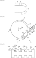
- the shape of the substrate is not particularly limited, and is typically a circle, but may be a polygon such as a quadrangle. In the present specification, as shown in FIG.
- a portion B whose cross-section has a curvature is called a "bevel”
- a region E closer to the bevel than a region D where a device is formed is called an "edge”.
- the bevel and the edge are collectively called a "peripheral portion”.
- FIG. 2 is a top view schematically showing an overview configuration of a substrate cleaning apparatus according to an embodiment.
- the substrate cleaning apparatus includes spindles 1, roll type cleaning members 2a and 2b, motors 3a and 3b, cleaning liquid nozzles 4a and 4b, rinse liquid nozzles 5a and 5b, and an actuator 6 (the cleaning liquid nozzle 4b and the rinse liquid nozzle 5b do not appear in FIG. 2 because they are located below the substrate W).
- the spindles 1 are an example of a substrate support mechanism and hold the peripheral portion of the substrate W with its surface facing up. Further, the spindles 1 in the present embodiment rotate the substrate W in a horizontal plane. More specifically, the substrate W is rotated by positioning the peripheral portion of the substrate W in a holding groove formed on an outer circumferential side surface of a piece provided in an upper portion of the spindle 1, inwardly pressing the peripheral portion of the substrate W, and rotating (auto-rotating) the piece.
- the "piece” can be paraphrased to a "holding portion” for holding the substrate.
- the "spindle” can be paraphrased to a "roller".
- the substrate W may be held and rotated by another method such as applying a spin chuck that sucks a lower surface of the substrate W and rotates the substrate W without using the spindles 1.
- the roll type cleaning member 2a cleans an upper surface of the substrate W and the roll type cleaning member 2b cleans a lower surface of the substrate W.
- the upper surface of the substrate W is a device surface where a device pattern is formed and the lower surface of the substrate W is a non-device surface where the device pattern is not formed.
- the non-device surface can be paraphrased to a back surface.
- the roll type cleaning member 2a cleans the upper surface of the substrate W by rotating while being in contact with the peripheral portion of the upper surface of the substrate W.
- the roll type cleaning member 2b is arranged facing the roll type cleaning member 2a, that is, arranged below the roll type cleaning member 2a.
- the roll type cleaning member 2b cleans the lower surface of the substrate W by rotating while being in contact with the peripheral portion of the lower surface of the substrate W.
- the roll type cleaning members 2a and 2b may be in contact with only one of the edge and the bevel.
- the roll type cleaning member 2a is connected to the motor 3a through a shaft 31a.
- the roll type cleaning member 2a is rotated by rotation of the motor 3a.
- a rotation direction of the roll type cleaning member 2a is a direction from the center to the edge of the substrate W (counterclockwise as seen from an arrow B) at a position where the roll type cleaning member 2a is in contact with the substrate W.
- the roll type cleaning member 2a can be moved in the radial direction of the substrate W by the actuator 6.
- the roll type cleaning member 2a is located at a position away from the position where the substrate W is arranged in a direction perpendicular to an outer circumferential direction. This position is called a "retreat position".
- the roll type cleaning member 2a moves toward the center of the substrate W from the retreat position and comes into contact with the substrate W. This position is called a "cleaning position”.
- the roll type cleaning member 2a moves in the direction perpendicular to the outer circumferential direction of the substrate W toward the retreat position.
- the cleaning liquid nozzle 4b and the rinse liquid nozzle 5b are arranged below the substrate W and supply liquids to the lower surface of the substrate W when the substrate W is cleaned.
- the others are the same as those of the cleaning liquid nozzle 4a and the rinse liquid nozzle 5a.
- FIG. 3 is a front view of the roll type cleaning member 2a (a view seen from an arrow A of FIG. 2 ).
- large diameter portions 21a and small diameter portions 22a are alternately stacked to form recesses and projections.
- the roll type cleaning member 2a can be considered to have a cylindrical shape where a plurality of grooves 23a is formed in a circumferential direction. Alternatively, it can be considered that recesses and projections are formed on the roll type cleaning member 2a in a longitudinal direction (axis direction).
- the groove 23a becomes a ring closed between surfaces perpendicular to a rotation axis of the roll type cleaning member 2a.
- FIG. 3 there are five corner portions 211a in the roll type cleaning member 2a, so that the peripheral portion of the substrate W repeats contact and separation with respect to the corner portion 211a five times during one rotation of the substrate W.
- a particle removal mechanism of the roll type cleaning member 2a it is considered that a great effect is produced by a physical force generated when the corner portions 211a of the roll type cleaning member 2a come into contact with and wipe the substrate W, and further, a physical force can be periodically and repeatedly applied to particles, so that high particle removal performance can be obtained.
- the cleaning liquid nozzles 4a and 4b and the rinse liquid nozzles 5a and 5b supply a cleaning liquid in a direction toward the edge of the substrate W.
- the roll type cleaning members 2a and 2b rotate so that rotation directions of the roll type cleaning members 2a and 2b at positions where the roll type cleaning members 2a and 2b are in contact with the substrate W are directions toward the edge of the substrate W. That is, the cleaning liquid is supplied in a direction where the liquid is flowed into the rotations of the roll type cleaning members 2a and 2b. Thereby, fresh liquid can be smoothly supplied between the substrate and the roll type cleaning members 2a and 2b.
- the cleaning liquid nozzles 4a and 4b and the rinse liquid nozzles 5a and 5b need not necessarily supply the liquid onto the substrate W, but may supply the liquid to a portion where the substrate W and the roll type cleaning members 2a and 2b are in contact with each other (cross each other) or a portion near the contact portion. Alternatively, the liquid may be supplied to two or more of a portion on the substrate W, the contact portion, and the portion near the contact portion. In any case, it is desirable that the cleaning liquid and the rinse liquid are supplied to the substrate W in a direction in which the liquids are discharged to the outside of the substrate W.
- the roll type cleaning members 2a and 2b have cores 24a and 24b which are rotating mechanisms to be rotation axes and which extend in parallel with the substrate W.
- the liquid may be supplied to the insides of the cores 24a and 24b (so-called “inner rinse”).
- the supplied liquid is moved from the insides of the cores 24a and 24b to the surfaces (cleaning surfaces) of the roll type cleaning members 2a and 2b by centrifugal forces generated by the rotations of the roll type cleaning members 2a and 2b and supplied to the substrate W.
- the external supply of the liquid from the cleaning liquid nozzles 4a and 4b and the rinse liquid nozzles 5a and 5b may be combined with the inner rinse.
- the roll type cleaning members 2a and 2b may be combined with or integrated with the cores 24a and 24b in advance before the roll type cleaning members 2a and 2b are used in the substrate cleaning apparatus.
- the roll type cleaning members 2a and 2b may only have holes where the cores 24a and 24b will be inserted, and the roll type cleaning members 2a and 2b may be used by inserting the cores 24a and 24b included in the substrate cleaning apparatus into the holes.
- the roll type cleaning members 2a and 2b have the large diameter portions 21a and 21b and the small diameter portions 22a and 22b. Therefore, the corner portions 211a of the large diameter portions 21a and 21b repeatedly come into contact with the substrate W and thereby physical cleaning performance is increased, and the cleaning liquid is held by the side surfaces 212a used as walls and thereby a cleaning effect by the cleaning liquid is increased and the cleaning performance is improved.
- the centers of the cores 24a and 24b of the roll type cleaning members 2a and 2b are distant from the center in the thickness direction of the substrate W by distances D1 and D2, respectively.
- the distances D1 and D2 may be equal or different from each other.
- the distances D1 and D2 may be arbitrarily set by recipe.
- the roll type cleaning members 2a and 2b may be moved (swung) in the vertical direction so that the distances D1 and D2 vary during cleaning. A portion to be cleaned can be adjusted according to an adhesion situation of particles or the like.
- the roll type cleaning members 2a and 2b may include fine abrasive grains, fluorine-based resin particles, catalyst particles, or the like.
- the cleaning may be performed by holding the substrate W in the vertical direction instead of the horizontal direction.
- the roll type cleaning members 2a and 2b need not necessarily be provided above and below the substrate W, but the substrate cleaning apparatus may include only the roll type cleaning member 2a that cleans the upper surface of the substrate W. In this case, the distance D1 may be 0.
- the substrate cleaning apparatus may include only the roll type cleaning member 2b that cleans the lower surface of the substrate W. In this case, the distance D2 may be 0.
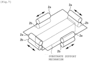
- the roll type cleaning members 2a and 2b can be applied to cleaning of a polygonal (for example, rectangular) substrate.
- a substrate support moving mechanism of the substrate support mechanism moves a rectangular substrate along one side in a horizontal posture
- peripheral portions of the rectangular substrate may be cleaned by causing the roll type cleaning members 2a and 2b to come into contact with the substrate along a moving direction.
- FIG. 7 it is allowed that the substrate is fixed and the roll type cleaning members 2a and 2b are moved along the sides.
Landscapes
- Engineering & Computer Science (AREA)
- Physics & Mathematics (AREA)
- Condensed Matter Physics & Semiconductors (AREA)
- General Physics & Mathematics (AREA)
- Manufacturing & Machinery (AREA)
- Computer Hardware Design (AREA)
- Microelectronics & Electronic Packaging (AREA)
- Power Engineering (AREA)
- Cleaning Or Drying Semiconductors (AREA)
- Cleaning In General (AREA)
- Cleaning By Liquid Or Steam (AREA)
- Manufacturing Of Printed Wiring (AREA)
Applications Claiming Priority (1)
| Application Number | Priority Date | Filing Date | Title |
|---|---|---|---|
| JP2018193312A JP7166132B2 (ja) | 2018-10-12 | 2018-10-12 | 基板洗浄部材および基板洗浄装置 |
Publications (2)
| Publication Number | Publication Date |
|---|---|
| EP3636356A1 EP3636356A1 (en) | 2020-04-15 |
| EP3636356B1 true EP3636356B1 (en) | 2024-12-18 |
Family
ID=68280895
Family Applications (1)
| Application Number | Title | Priority Date | Filing Date |
|---|---|---|---|
| EP19202831.4A Active EP3636356B1 (en) | 2018-10-12 | 2019-10-11 | Substrate cleaning member and substrate cleaning apparatus |
Country Status (7)
Families Citing this family (2)
| Publication number | Priority date | Publication date | Assignee | Title |
|---|---|---|---|---|
| KR20210124087A (ko) | 2020-04-06 | 2021-10-14 | 주식회사 엘지화학 | 전기화학소자용 분리막 및 이를 제조하는 방법 |
| JP6892176B1 (ja) * | 2020-11-19 | 2021-06-23 | 不二越機械工業株式会社 | ワーク洗浄装置 |
Citations (1)
| Publication number | Priority date | Publication date | Assignee | Title |
|---|---|---|---|---|
| EP3608948A1 (en) * | 2018-08-09 | 2020-02-12 | Ebara Corporation | Substrate cleaning tool, substrate cleaning apparatus, substrate processing apparatus, substrate processing method, and method of manufacturing substrate cleaning tool |
Family Cites Families (17)
| Publication number | Priority date | Publication date | Assignee | Title |
|---|---|---|---|---|
| GB772599A (en) | 1954-01-23 | 1957-04-17 | Service Eng Ltd | Improvements relating to brushing machines |
| US5375291A (en) | 1992-05-18 | 1994-12-27 | Tokyo Electron Limited | Device having brush for scrubbing substrate |
| US5937469A (en) | 1996-12-03 | 1999-08-17 | Intel Corporation | Apparatus for mechanically cleaning the edges of wafers |
| JPH11283952A (ja) * | 1998-03-30 | 1999-10-15 | Shibaura Mechatronics Corp | ブラシ洗浄装置 |
| US6299698B1 (en) * | 1998-07-10 | 2001-10-09 | Applied Materials, Inc. | Wafer edge scrubber and method |
| US6467120B1 (en) * | 1999-09-08 | 2002-10-22 | International Business Machines Corporation | Wafer cleaning brush profile modification |
| US20040040576A1 (en) | 2002-08-29 | 2004-03-04 | Yuxia Sun | Wafer cleaning brush |
| KR100562502B1 (ko) * | 2003-07-02 | 2006-03-21 | 삼성전자주식회사 | 반도체 기판의 가장자리부 처리 장치 및 방법 |
| JP3933670B2 (ja) | 2005-03-29 | 2007-06-20 | 東京エレクトロン株式会社 | 基板洗浄方法及び基板洗浄装置 |
| JP4768556B2 (ja) | 2006-09-15 | 2011-09-07 | Nec液晶テクノロジー株式会社 | 基板洗浄装置及び基板洗浄方法 |
| JP2007272236A (ja) * | 2007-04-11 | 2007-10-18 | Advanced Display Inc | 基板端面洗浄装置、基板端面洗浄方法及び半導体装置の製造方法 |
| JP2008282865A (ja) | 2007-05-08 | 2008-11-20 | Fuji Electric Device Technology Co Ltd | スクラブ洗浄装置及びそれに用いられるロールスポンジアセンブリ |
| KR101020676B1 (ko) * | 2008-11-26 | 2011-03-09 | 세메스 주식회사 | 기판 세정 장치 |
| WO2010125663A1 (ja) * | 2009-04-30 | 2010-11-04 | アイオン株式会社 | 洗浄用スポンジローラ |
| JP5535687B2 (ja) | 2010-03-01 | 2014-07-02 | 株式会社荏原製作所 | 基板洗浄方法及び基板洗浄装置 |
| JP5645752B2 (ja) * | 2011-05-25 | 2014-12-24 | 株式会社荏原製作所 | 基板洗浄方法及びロール洗浄部材 |
| US9704729B2 (en) * | 2013-06-13 | 2017-07-11 | K.C. Tech Co., Ltd. | Substrate cleaning apparatus and method and brush assembly used therein |
-
2018
- 2018-10-12 JP JP2018193312A patent/JP7166132B2/ja active Active
-
2019
- 2019-09-10 TW TW108132505A patent/TWI820206B/zh active
- 2019-10-08 KR KR1020190124316A patent/KR102708935B1/ko active Active
- 2019-10-10 US US16/598,728 patent/US11501983B2/en active Active
- 2019-10-11 SG SG10201909509UA patent/SG10201909509UA/en unknown
- 2019-10-11 CN CN201910964641.1A patent/CN111048442B/zh active Active
- 2019-10-11 EP EP19202831.4A patent/EP3636356B1/en active Active
Patent Citations (1)
| Publication number | Priority date | Publication date | Assignee | Title |
|---|---|---|---|---|
| EP3608948A1 (en) * | 2018-08-09 | 2020-02-12 | Ebara Corporation | Substrate cleaning tool, substrate cleaning apparatus, substrate processing apparatus, substrate processing method, and method of manufacturing substrate cleaning tool |
Also Published As
| Publication number | Publication date |
|---|---|
| US20200118843A1 (en) | 2020-04-16 |
| TW202017030A (zh) | 2020-05-01 |
| JP7166132B2 (ja) | 2022-11-07 |
| KR102708935B1 (ko) | 2024-09-25 |
| US11501983B2 (en) | 2022-11-15 |
| TWI820206B (zh) | 2023-11-01 |
| CN111048442B (zh) | 2024-10-11 |
| CN111048442A (zh) | 2020-04-21 |
| EP3636356A1 (en) | 2020-04-15 |
| KR20200041791A (ko) | 2020-04-22 |
| SG10201909509UA (en) | 2020-05-28 |
| JP2020061514A (ja) | 2020-04-16 |
Similar Documents
| Publication | Publication Date | Title |
|---|---|---|
| KR100632412B1 (ko) | 세정장치 | |
| KR102661661B1 (ko) | 기판 세정 장치 | |
| KR100695980B1 (ko) | 기판세정장치 | |
| JP6587379B2 (ja) | 研磨装置 | |
| US7743449B2 (en) | System and method for a combined contact and non-contact wafer cleaning module | |
| JP6710129B2 (ja) | 基板洗浄装置および基板洗浄方法 | |
| EP3636356B1 (en) | Substrate cleaning member and substrate cleaning apparatus | |
| JP6887371B2 (ja) | 基板処理装置、基板処理装置の制御方法、プログラムを格納した記憶媒体 | |
| JP2024160411A (ja) | 基板洗浄装置、基板の洗浄方法 | |
| JP2007044693A (ja) | 洗浄装置 | |
| JP2019091886A (ja) | 基板処理装置および基板処理方法 | |
| US7007333B1 (en) | System and method for a combined contact and non-contact wafer cleaning module | |
| JP7470785B2 (ja) | 洗浄装置および洗浄方法 | |
| TW202212004A (zh) | 清洗構件安裝機構及基板清洗裝置 | |
| JP6625461B2 (ja) | 研磨装置 | |
| JP4963411B2 (ja) | 半導体装置または半導体ウェハの製造方法 | |
| JP2015035471A (ja) | 基板洗浄装置及び基板処理装置 | |
| EP3396707B1 (en) | Apparatus and method for cleaning a back surface of a substrate | |
| KR20190087712A (ko) | 기판 처리 장치 | |
| WO2022186227A1 (ja) | ブラシローラ | |
| KR20230173453A (ko) | 내경이 확장된 웨이퍼 세정용 브러쉬 | |
| WO2025120716A1 (ja) | 基板処理方法及び基板処理システム | |
| JP2022176545A (ja) | 洗浄処理装置 | |
| JP2004209644A (ja) | 基板の研磨方法及び装置 |
Legal Events
| Date | Code | Title | Description |
|---|---|---|---|
| PUAI | Public reference made under article 153(3) epc to a published international application that has entered the european phase |
Free format text: ORIGINAL CODE: 0009012 |
|
| STAA | Information on the status of an ep patent application or granted ep patent |
Free format text: STATUS: THE APPLICATION HAS BEEN PUBLISHED |
|
| AK | Designated contracting states |
Kind code of ref document: A1 Designated state(s): AL AT BE BG CH CY CZ DE DK EE ES FI FR GB GR HR HU IE IS IT LI LT LU LV MC MK MT NL NO PL PT RO RS SE SI SK SM TR |
|
| AX | Request for extension of the european patent |
Extension state: BA ME |
|
| STAA | Information on the status of an ep patent application or granted ep patent |
Free format text: STATUS: REQUEST FOR EXAMINATION WAS MADE |
|
| 17P | Request for examination filed |
Effective date: 20201015 |
|
| RBV | Designated contracting states (corrected) |
Designated state(s): AL AT BE BG CH CY CZ DE DK EE ES FI FR GB GR HR HU IE IS IT LI LT LU LV MC MK MT NL NO PL PT RO RS SE SI SK SM TR |
|
| STAA | Information on the status of an ep patent application or granted ep patent |
Free format text: STATUS: EXAMINATION IS IN PROGRESS |
|
| 17Q | First examination report despatched |
Effective date: 20221130 |
|
| RAP3 | Party data changed (applicant data changed or rights of an application transferred) |
Owner name: EBARA CORPORATION |
|
| REG | Reference to a national code |
Ref country code: DE Ref legal event code: R079 Free format text: PREVIOUS MAIN CLASS: B08B0001040000 Ipc: B08B0001320000 Ref country code: DE Ref legal event code: R079 Ref document number: 602019063579 Country of ref document: DE Free format text: PREVIOUS MAIN CLASS: B08B0001040000 Ipc: B08B0001320000 |
|
| GRAP | Despatch of communication of intention to grant a patent |
Free format text: ORIGINAL CODE: EPIDOSNIGR1 |
|
| STAA | Information on the status of an ep patent application or granted ep patent |
Free format text: STATUS: GRANT OF PATENT IS INTENDED |
|
| RIC1 | Information provided on ipc code assigned before grant |
Ipc: H01L 21/67 20060101ALI20240620BHEP Ipc: B08B 1/32 20240101AFI20240620BHEP |
|
| INTG | Intention to grant announced |
Effective date: 20240708 |
|
| GRAS | Grant fee paid |
Free format text: ORIGINAL CODE: EPIDOSNIGR3 |
|
| GRAA | (expected) grant |
Free format text: ORIGINAL CODE: 0009210 |
|
| STAA | Information on the status of an ep patent application or granted ep patent |
Free format text: STATUS: THE PATENT HAS BEEN GRANTED |
|
| AK | Designated contracting states |
Kind code of ref document: B1 Designated state(s): AL AT BE BG CH CY CZ DE DK EE ES FI FR GB GR HR HU IE IS IT LI LT LU LV MC MK MT NL NO PL PT RO RS SE SI SK SM TR |
|
| REG | Reference to a national code |
Ref country code: CH Ref legal event code: EP |
|
| REG | Reference to a national code |
Ref country code: DE Ref legal event code: R096 Ref document number: 602019063579 Country of ref document: DE |
|
| P01 | Opt-out of the competence of the unified patent court (upc) registered |
Free format text: CASE NUMBER: APP_64730/2024 Effective date: 20241206 |
|
| REG | Reference to a national code |
Ref country code: IE Ref legal event code: FG4D |
|
| REG | Reference to a national code |
Ref country code: LT Ref legal event code: MG9D |
|
| PG25 | Lapsed in a contracting state [announced via postgrant information from national office to epo] |
Ref country code: HR Free format text: LAPSE BECAUSE OF FAILURE TO SUBMIT A TRANSLATION OF THE DESCRIPTION OR TO PAY THE FEE WITHIN THE PRESCRIBED TIME-LIMIT Effective date: 20241218 |
|
| PG25 | Lapsed in a contracting state [announced via postgrant information from national office to epo] |
Ref country code: FI Free format text: LAPSE BECAUSE OF FAILURE TO SUBMIT A TRANSLATION OF THE DESCRIPTION OR TO PAY THE FEE WITHIN THE PRESCRIBED TIME-LIMIT Effective date: 20241218 |
|
| PG25 | Lapsed in a contracting state [announced via postgrant information from national office to epo] |
Ref country code: BG Free format text: LAPSE BECAUSE OF FAILURE TO SUBMIT A TRANSLATION OF THE DESCRIPTION OR TO PAY THE FEE WITHIN THE PRESCRIBED TIME-LIMIT Effective date: 20241218 |
|
| PG25 | Lapsed in a contracting state [announced via postgrant information from national office to epo] |
Ref country code: NO Free format text: LAPSE BECAUSE OF FAILURE TO SUBMIT A TRANSLATION OF THE DESCRIPTION OR TO PAY THE FEE WITHIN THE PRESCRIBED TIME-LIMIT Effective date: 20250318 |
|
| REG | Reference to a national code |
Ref country code: NL Ref legal event code: MP Effective date: 20241218 |
|
| PG25 | Lapsed in a contracting state [announced via postgrant information from national office to epo] |
Ref country code: GR Free format text: LAPSE BECAUSE OF FAILURE TO SUBMIT A TRANSLATION OF THE DESCRIPTION OR TO PAY THE FEE WITHIN THE PRESCRIBED TIME-LIMIT Effective date: 20250319 Ref country code: LV Free format text: LAPSE BECAUSE OF FAILURE TO SUBMIT A TRANSLATION OF THE DESCRIPTION OR TO PAY THE FEE WITHIN THE PRESCRIBED TIME-LIMIT Effective date: 20241218 |
|
| PG25 | Lapsed in a contracting state [announced via postgrant information from national office to epo] |
Ref country code: RS Free format text: LAPSE BECAUSE OF FAILURE TO SUBMIT A TRANSLATION OF THE DESCRIPTION OR TO PAY THE FEE WITHIN THE PRESCRIBED TIME-LIMIT Effective date: 20250318 |
|
| PG25 | Lapsed in a contracting state [announced via postgrant information from national office to epo] |
Ref country code: NL Free format text: LAPSE BECAUSE OF FAILURE TO SUBMIT A TRANSLATION OF THE DESCRIPTION OR TO PAY THE FEE WITHIN THE PRESCRIBED TIME-LIMIT Effective date: 20241218 |
|
| REG | Reference to a national code |
Ref country code: AT Ref legal event code: MK05 Ref document number: 1751849 Country of ref document: AT Kind code of ref document: T Effective date: 20241218 |
|
| PG25 | Lapsed in a contracting state [announced via postgrant information from national office to epo] |
Ref country code: SM Free format text: LAPSE BECAUSE OF FAILURE TO SUBMIT A TRANSLATION OF THE DESCRIPTION OR TO PAY THE FEE WITHIN THE PRESCRIBED TIME-LIMIT Effective date: 20241218 |
|
| PG25 | Lapsed in a contracting state [announced via postgrant information from national office to epo] |
Ref country code: PL Free format text: LAPSE BECAUSE OF FAILURE TO SUBMIT A TRANSLATION OF THE DESCRIPTION OR TO PAY THE FEE WITHIN THE PRESCRIBED TIME-LIMIT Effective date: 20241218 |
|
| PG25 | Lapsed in a contracting state [announced via postgrant information from national office to epo] |
Ref country code: ES Free format text: LAPSE BECAUSE OF FAILURE TO SUBMIT A TRANSLATION OF THE DESCRIPTION OR TO PAY THE FEE WITHIN THE PRESCRIBED TIME-LIMIT Effective date: 20241218 |
|
| PG25 | Lapsed in a contracting state [announced via postgrant information from national office to epo] |
Ref country code: IS Free format text: LAPSE BECAUSE OF FAILURE TO SUBMIT A TRANSLATION OF THE DESCRIPTION OR TO PAY THE FEE WITHIN THE PRESCRIBED TIME-LIMIT Effective date: 20250418 |
|
| PG25 | Lapsed in a contracting state [announced via postgrant information from national office to epo] |
Ref country code: PT Free format text: LAPSE BECAUSE OF FAILURE TO SUBMIT A TRANSLATION OF THE DESCRIPTION OR TO PAY THE FEE WITHIN THE PRESCRIBED TIME-LIMIT Effective date: 20250421 |
|
| PG25 | Lapsed in a contracting state [announced via postgrant information from national office to epo] |
Ref country code: EE Free format text: LAPSE BECAUSE OF FAILURE TO SUBMIT A TRANSLATION OF THE DESCRIPTION OR TO PAY THE FEE WITHIN THE PRESCRIBED TIME-LIMIT Effective date: 20241218 |
|
| PG25 | Lapsed in a contracting state [announced via postgrant information from national office to epo] |
Ref country code: AT Free format text: LAPSE BECAUSE OF FAILURE TO SUBMIT A TRANSLATION OF THE DESCRIPTION OR TO PAY THE FEE WITHIN THE PRESCRIBED TIME-LIMIT Effective date: 20241218 Ref country code: RO Free format text: LAPSE BECAUSE OF FAILURE TO SUBMIT A TRANSLATION OF THE DESCRIPTION OR TO PAY THE FEE WITHIN THE PRESCRIBED TIME-LIMIT Effective date: 20241218 |
|
| PG25 | Lapsed in a contracting state [announced via postgrant information from national office to epo] |
Ref country code: SK Free format text: LAPSE BECAUSE OF FAILURE TO SUBMIT A TRANSLATION OF THE DESCRIPTION OR TO PAY THE FEE WITHIN THE PRESCRIBED TIME-LIMIT Effective date: 20241218 |
|
| PG25 | Lapsed in a contracting state [announced via postgrant information from national office to epo] |
Ref country code: CZ Free format text: LAPSE BECAUSE OF FAILURE TO SUBMIT A TRANSLATION OF THE DESCRIPTION OR TO PAY THE FEE WITHIN THE PRESCRIBED TIME-LIMIT Effective date: 20241218 |
|
| PG25 | Lapsed in a contracting state [announced via postgrant information from national office to epo] |
Ref country code: IT Free format text: LAPSE BECAUSE OF FAILURE TO SUBMIT A TRANSLATION OF THE DESCRIPTION OR TO PAY THE FEE WITHIN THE PRESCRIBED TIME-LIMIT Effective date: 20241218 |