EP3636069B1 - Gutter for an evaporative pad of a cooling system - Google Patents
Gutter for an evaporative pad of a cooling system Download PDFInfo
- Publication number
- EP3636069B1 EP3636069B1 EP18425078.5A EP18425078A EP3636069B1 EP 3636069 B1 EP3636069 B1 EP 3636069B1 EP 18425078 A EP18425078 A EP 18425078A EP 3636069 B1 EP3636069 B1 EP 3636069B1
- Authority
- EP
- European Patent Office
- Prior art keywords
- channel element
- joint
- gutter
- inner part
- panel
- Prior art date
- Legal status (The legal status is an assumption and is not a legal conclusion. Google has not performed a legal analysis and makes no representation as to the accuracy of the status listed.)
- Active
Links
Images


Classifications
-
- A—HUMAN NECESSITIES
- A01—AGRICULTURE; FORESTRY; ANIMAL HUSBANDRY; HUNTING; TRAPPING; FISHING
- A01K—ANIMAL HUSBANDRY; AVICULTURE; APICULTURE; PISCICULTURE; FISHING; REARING OR BREEDING ANIMALS, NOT OTHERWISE PROVIDED FOR; NEW BREEDS OF ANIMALS
- A01K1/00—Housing animals; Equipment therefor
- A01K1/0047—Air-conditioning, e.g. ventilation, of animal housings
- A01K1/0082—Water misting or cooling systems
-
- A—HUMAN NECESSITIES
- A01—AGRICULTURE; FORESTRY; ANIMAL HUSBANDRY; HUNTING; TRAPPING; FISHING
- A01G—HORTICULTURE; CULTIVATION OF VEGETABLES, FLOWERS, RICE, FRUIT, VINES, HOPS OR SEAWEED; FORESTRY; WATERING
- A01G9/00—Cultivation in receptacles, forcing-frames or greenhouses; Edging for beds, lawn or the like
- A01G9/24—Devices or systems for heating, ventilating, regulating temperature, illuminating, or watering, in greenhouses, forcing-frames, or the like
- A01G9/246—Air-conditioning systems
-
- F—MECHANICAL ENGINEERING; LIGHTING; HEATING; WEAPONS; BLASTING
- F16—ENGINEERING ELEMENTS AND UNITS; GENERAL MEASURES FOR PRODUCING AND MAINTAINING EFFECTIVE FUNCTIONING OF MACHINES OR INSTALLATIONS; THERMAL INSULATION IN GENERAL
- F16L—PIPES; JOINTS OR FITTINGS FOR PIPES; SUPPORTS FOR PIPES, CABLES OR PROTECTIVE TUBING; MEANS FOR THERMAL INSULATION IN GENERAL
- F16L41/00—Branching pipes; Joining pipes to walls
- F16L41/08—Joining pipes to walls or pipes, the joined pipe axis being perpendicular to the plane of a wall or to the axis of another pipe
Definitions
- the present invention refers in general to evaporative cooling systems, used, for example, for livestock and greenhouse facilities.
- Such systems use water evaporation to cool the air that is circulated inside a barn or greenhouse by means of aeration systems.
- water-impregnated evaporative panels are used, which are arranged in openings made in the walls of the building and are made to be penetrated by a flow of air generated by an aeration system.
- the water in the panel evaporates, extracting heat from the surrounding air, and therefore the hot, dry air from the outside enters the cooler, more humid building.
- the water that does not evaporate, dripping downwards by gravity collects in a gutter located below the panel, from which the water is drawn up by a pump and fed back to the distribution apparatus.
- Evaporative panels generally are relatively large structures and are thus made by joining several elements together in order to cover the desired areas.
- the collection gutters are made by joining several consecutive elements in order to cover the entire width of the panel.
- the assembly generally takes place on site and provides for fixing and sealing the various elements of the gutter to each other.
- the fixing and sealing operation is carried out manually, and therefore the final result, in terms of sealing the gutter, depends on the skills of the operator. Moreover, it is also a time-consuming and resource-intensive process.
- US 3 841 101 A discloses a gutter having the features of the preamble of claim 1, which is however not suitable for evaporative cooling systems.
- DE 299 08 553 U1 discloses a joint which is used for fixing a repair piece to a gutter.
- FR 682 616 A discloses a joint allowing two gutter elements to be assembled in an overlapping relationship.
- One object of the present invention is to make available a gutter for an evaporative panel of a cooling system that can overcome at least in part the aforementioned drawbacks.
- a gutter for an evaporative panel of a cooling system according to claim 1.
- Such a gutter comprises
- a channel element of the gutter is achieved by means of a joint that may also ensure a seal between the elements.
- the joint thus facilitates assembly and sealing operations, for which the same level of expertise is not required as for conventional gutters. Moreover, assembly times are comparatively short.
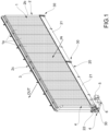
- an evaporative cooling system is represented.
- the system comprises an evaporative panel 1, formed by a plurality of panel elements 1a placed side by side and supported by a structure 2 that surrounds the panel 1.
- the elements of panel 1a are made of material chosen and configured in such a way as to allow, on the one hand, for them to be impregnated with water, and, on the other, for the air to pass through them.
- the direction of the air flow is represented by the IN and OUT arrows in figure 1 .
- the structure 2 comprises two side panels, 2a and 2b, between which the evaporative panel 1 is laterally contained.
- An upper part 2c, in which a distribution apparatus 3 is arranged, is constructed as a pipe that extends along the entire width of the panel 1 and equipped with a plurality of spray nozzles or other dispensing members (not shown) distributed along the pipe so as to spray the panel with water as evenly as possible.
- the structure 2 further comprises a lower part 20 constructed as a gutter, and suitable to collect the water that drips by gravity from the panel 1.
- the gutter 20 is conventionally connected to the distribution apparatus 3 by means of a recirculation pipe 4, comprising a pump 5 to draw the water from the gutter 20 and to feed it to the distribution apparatus 3.
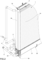
- the gutter 20 comprises a plurality of consecutive channel elements 21. Each end of each channel element 21 is sealingly connected to one end of an adjacent channel element 21, or to another component of the panel, in particular an end cap of the gutter 21.
- Figures 1 and 2 show one of such end caps, indicated at 22, on which is arranged a fitting for connecting the gutter 21 to the recirculation pipe 4.
- Each channel element 21 is made in a single piece, in particular, of plastic material, but could be made of other materials, such as metallic materials.
- the channel elements 21 have an approximately trapezoidal cross section. Such shape is not, however, essential to the invention and may be different, e.g. semicircular, parabolic or semi-elliptical, or more generally it may also have a non-symmetrical shape.
- Each channel element 21 consists of a bottom wall 21a and a pair of side walls 21b opposite each other that extend from the bottom wall 21a and end in respective top edges 21c of the channel element 21.
- each wall 21a and 21b is preferably constructed as a double wall with a cavity 21d inside. Such configuration is advantageous because it provides a double barrier that prevents water leaks to the outside in the event of cracks forming on the inside of the double wall.
- a series of consecutive grid elements 23 is arranged along the gutter 20, which rest on the top edges 21c of each channel element 21 and act as a support for the panel elements 1a, while at the same time allowing the water dripping from the panel elements 1a to collect in the gutter 20.
- the sealed connection between the channel elements 21, and between the channel elements 21 and the end caps 22, is made by means of joints 30.
- Each joint 30 comprises an outer part 31 formed as a single piece, in particular, made of plastic (or other materials), which is configured to be coupled to the outer surface of the channel element 21. Consequently, the outer part 31 of the joint has a shape that matches the cross-sectional profile of the outer surface of the channel element 21.
- the outer part 31 of the joint comprises a base portion 31a, which may be placed on a surface, and a pair of opposing side portions 31b that extend from the base portion 31a. At the top ends thereof, the side portions 31b end with their respective flanges 31c that extend laterally outwards. As may be seen in figure 3 , in use, the flanges 31c are arranged at the respective top edges 21c of the channel element 21.
- the outer part 31 of the joint 30 has a seat 32 in the shape of a saddle, defined by the inner surfaces of the base portion 31a and the side portions 31b of the outer part 31.
- the seat 32 is suitable to receive the end of a respective channel element 21.
- the outer part 31, and in general the whole joint 30, may have reflective symmetry with respect to a median plane, so as to allow the coupling of two gutter elements 21 arranged head to head with a single joint 30 (the term "median" is understood to refer to the direction defined by the longitudinal axis of the channel element 21).
- the following description refers to only one of the symmetrical halves of the joint 30, but it is intended that the features described concern both halves.
- the invention is not limited to the symmetrical example described herein, as the joint may also have a non-symmetrical shape.
- a partition 33 is preferably made, extending transversely inwards, arranged in particular at the median plane of the joint 30.
- the partition 33 defines a reference position, and possible abutment, for the end of the channel element 21 (and therefore, on opposite sides, for the ends of two channel elements 21 placed head to head).
- the end of the channel element 21 must be placed at a certain axial distance from the partition 33, so as to have play that may compensate for the thermal expansion of the components that may occur in use.
- a groove 32a may be obtained suitable to receive a possible gasket (not illustrated) to be interposed between the outer part 31 of the joint 30 and the outer surface of the channel element 21.
- a possible gasket (not illustrated) to be interposed between the outer part 31 of the joint 30 and the outer surface of the channel element 21.
- the gasket(s) may be co-molded on the outer part 31 of the joint 30.
- Each joint 30 comprises moreover an inner part 35 formed as a single piece, in particular, made of plastic (or other materials), which is configured to be coupled to the inner surface of the channel element 21. Consequently, the inner part 35 of the joint has a shape that matches the cross-sectional profile of the outer surface of the channel element 21.
- the inner part 35 of the joint 30 has a saddle shape and comprises a bottom portion 35a and a pair of opposing side portions 35b that extend from the bottom portion 35a. At the top ends thereof, the side portions 35b end with their respective flanges 35c extending laterally outwards.
- the flanges 35c of the inner part 35 of the joint 30 are arranged at the respective top edges 21c of the channel element 21 and are superimposed on the flanges 31c of the outer part 31 of the joint 30.
- the end of the channel element 21 is sandwiched between the outer part 31 and the inner part 35 of the joint 30.
- each slit 35e is sized in length in such a way as to provide visual feedback regarding the positioning of the end of the channel element.
- the slit 35e is "empty" inasmuch as, according to a plan view, there is no overlap between the slit 35e and the end of the channel element 21.
- the slit 35e is "full” inasmuch as, according to a plan view, there is a total overlap between the slit 35e and the end of the channel element 21.
- a slit 36 is preferably made to receive the partition 33 of the outer part 31 of the joint 30.
- one or more bridge portions 37a, 37b are made, extending between the side portions 35b of the inner part 35. Some of the bridge portions, indicated at 37a, serve to stiffen the inner part 35 of the joint 30 and to prevent the side portions 35b from flexing inwards in use, which would result in a loss of effectiveness of the compressive action of the inner part 35 of the joint 30 on the inner surface of the channel element 21.
- the upper bridge portion, indicated at 37b is made as a grid and serves as a support for the overhanging panel element 1a.
- a groove 35d may be obtained suitable to receive a respective gasket 38 to be interposed between the outer part 31 of the joint 30 and the outer surface of the channel element 21.
- the gasket(s) may be co-molded on the inner part 35 of the joint 30.
- the joint 31 further comprises clamping devices 39 acting on the flanges 35c and 31c to clamp the end of the channel element 21 between the inner part 35 and outer part 31 of the joint 30.
- the clamping devices 39 are made as screws that are inserted into holes 39a made in the flanges 35c on the inner part 35 of the joint 30 and coupled to threaded holes 39b made in the flanges 31c on the outer part 31 of the joint 30.
- Clamping devices 39 may have other configurations. For example, they could be made as snap-on devices, or as clips or clamps that embrace and fasten the flanges 35c and 31c together.
Landscapes
- Life Sciences & Earth Sciences (AREA)
- Environmental Sciences (AREA)
- Zoology (AREA)
- Animal Husbandry (AREA)
- Biodiversity & Conservation Biology (AREA)
- Engineering & Computer Science (AREA)
- General Engineering & Computer Science (AREA)
- Mechanical Engineering (AREA)
- Heat-Exchange Devices With Radiators And Conduit Assemblies (AREA)
Priority Applications (3)
| Application Number | Priority Date | Filing Date | Title |
|---|---|---|---|
| EP18425078.5A EP3636069B1 (en) | 2018-10-10 | 2018-10-10 | Gutter for an evaporative pad of a cooling system |
| ES18425078T ES2992876T3 (en) | 2018-10-10 | 2018-10-10 | Gutter for an evaporative pad of a cooling system |
| CN201910464154.9A CN111011222B (zh) | 2018-10-10 | 2019-05-30 | 用于冷却系统的蒸发面板的檐槽 |
Applications Claiming Priority (1)
| Application Number | Priority Date | Filing Date | Title |
|---|---|---|---|
| EP18425078.5A EP3636069B1 (en) | 2018-10-10 | 2018-10-10 | Gutter for an evaporative pad of a cooling system |
Publications (3)
| Publication Number | Publication Date |
|---|---|
| EP3636069A1 EP3636069A1 (en) | 2020-04-15 |
| EP3636069C0 EP3636069C0 (en) | 2024-10-30 |
| EP3636069B1 true EP3636069B1 (en) | 2024-10-30 |
Family
ID=64331992
Family Applications (1)
| Application Number | Title | Priority Date | Filing Date |
|---|---|---|---|
| EP18425078.5A Active EP3636069B1 (en) | 2018-10-10 | 2018-10-10 | Gutter for an evaporative pad of a cooling system |
Country Status (3)
| Country | Link |
|---|---|
| EP (1) | EP3636069B1 (es) |
| CN (1) | CN111011222B (es) |
| ES (1) | ES2992876T3 (es) |
Families Citing this family (1)
| Publication number | Priority date | Publication date | Assignee | Title |
|---|---|---|---|---|
| IT202100023189A1 (it) * | 2021-09-08 | 2023-03-08 | Gigola & Riccardi S P A | Pannelli evaporativi con bordi sagomati per l'accoppiamento con pannelli adiacenti o con rispettive strutture di supporto. |
Family Cites Families (19)
| Publication number | Priority date | Publication date | Assignee | Title |
|---|---|---|---|---|
| FR682616A (fr) * | 1929-10-02 | 1930-05-30 | Bride mobile à serrage progressif pour joint étanche souple à emboîtement de chéneaux et gouttières en ciment mélangé de matières fibreuses ou en toute autre composition | |
| ZA724540B (en) * | 1972-07-03 | 1974-06-26 | Duropenta Ltd | Improvements in or relating to gutter couplings |
| US4954015A (en) * | 1990-04-04 | 1990-09-04 | Gsw Inc. | Gutter seal |
| US5038528A (en) * | 1990-05-08 | 1991-08-13 | Gsw Inc. | Gasket seal |
| JPH0960217A (ja) * | 1995-08-28 | 1997-03-04 | Matsushita Electric Works Ltd | 軒樋継手 |
| JP3310583B2 (ja) * | 1997-05-15 | 2002-08-05 | 松下電工株式会社 | 軒樋継手 |
| JP3660786B2 (ja) * | 1997-08-05 | 2005-06-15 | 三菱樹脂株式会社 | 雨どいの接続構造 |
| DE69914541T2 (de) * | 1998-07-09 | 2004-12-16 | Ubbink Nederland B.V. | Kupplungsstück für Dachrinnen |
| JP2000064529A (ja) * | 1998-08-26 | 2000-02-29 | Matsushita Electric Works Ltd | 軒樋の継手構造 |
| DE29908553U1 (de) * | 1999-05-07 | 1999-08-12 | Senf, Reinhard, 14612 Falkensee | Rinnenverbindungs- und Sanierungsset |
| JP2002332724A (ja) * | 2001-05-07 | 2002-11-22 | Sekisui Chem Co Ltd | 軒樋のインサイドジョイント用固定治具 |
| JP2005273335A (ja) * | 2004-03-25 | 2005-10-06 | Matsushita Electric Works Ltd | 軒樋接続用継手 |
| US7350364B2 (en) * | 2006-01-17 | 2008-04-01 | Big Dutchman, Inc. | Evaporative cooling system for poultry houses and the like |
| JP4569480B2 (ja) * | 2006-01-25 | 2010-10-27 | パナソニック電工株式会社 | 内継手および軒樋継手 |
| JP2007315004A (ja) * | 2006-05-25 | 2007-12-06 | Matsushita Electric Works Ltd | 軒樋接続装置 |
| JP2007315103A (ja) * | 2006-05-26 | 2007-12-06 | Matsushita Electric Works Ltd | 軒樋の接続構造 |
| CN200968030Y (zh) * | 2006-11-07 | 2007-10-31 | 关健龙 | 便于接驳的集雨水槽接驳结构 |
| JP2010031518A (ja) * | 2008-07-28 | 2010-02-12 | Panasonic Electric Works Co Ltd | 内継手 |
| CN205189278U (zh) * | 2015-11-25 | 2016-04-27 | 杭州航达塑化有限公司 | 一种天沟连接结构 |
-
2018
- 2018-10-10 EP EP18425078.5A patent/EP3636069B1/en active Active
- 2018-10-10 ES ES18425078T patent/ES2992876T3/es active Active
-
2019
- 2019-05-30 CN CN201910464154.9A patent/CN111011222B/zh active Active
Also Published As
| Publication number | Publication date |
|---|---|
| CN111011222B (zh) | 2022-06-17 |
| ES2992876T3 (en) | 2024-12-19 |
| EP3636069C0 (en) | 2024-10-30 |
| EP3636069A1 (en) | 2020-04-15 |
| CN111011222A (zh) | 2020-04-17 |
Similar Documents
| Publication | Publication Date | Title |
|---|---|---|
| US9469983B2 (en) | Beam cap system | |
| US9441368B2 (en) | Construction system for releasing moisture from a hip, valley or gable roof | |
| US5195332A (en) | Fan coil unit with novel removable condensate pan | |
| DE2641708A1 (de) | Feuchtraumdecke | |
| EP3636069B1 (en) | Gutter for an evaporative pad of a cooling system | |
| US20190284825A1 (en) | Pool gutter with deck grate adapter | |
| US5456209A (en) | Preformed heated flooring system for stables and other animal shelters | |
| US20180080677A1 (en) | Panel for a module of an air handling unit | |
| WO2014100712A1 (en) | Condensate drain devices for heat exchanger coil and methods for making the same | |
| US20150099454A1 (en) | Practical flexible connecting apparatus for ventilation duct | |
| TWI621825B (zh) | Radiation panel device | |
| US11408638B2 (en) | Gutter for an evaporative panel of a cooling system | |
| DE69921763T2 (de) | Verdampfungskühler für eine Gasturbine | |
| US7610770B2 (en) | Cooling tower seal joint | |
| JP5394114B2 (ja) | 輻射パネル装置 | |
| JP2655807B2 (ja) | 冷却塔 | |
| BR102020001953B1 (pt) | Calha para um painel evaporativo de um sistema de refrigeração | |
| JP4351931B2 (ja) | 植物栽培容器 | |
| US20150292823A1 (en) | Liquid Distribution Device | |
| JPH10122760A (ja) | 冷却塔およびその温水分配管 | |
| BR102020001953A2 (pt) | Calha para um painel evaporativo de um sistema de refrigeração | |
| GB2084209A (en) | Repairing gutters | |
| JP3040772B1 (ja) | 冷却塔 | |
| US6474092B2 (en) | Apparatus and method for a blower cover | |
| US20130020728A1 (en) | Vertical agitator for wastewater received in a sedimentation tank |
Legal Events
| Date | Code | Title | Description |
|---|---|---|---|
| PUAI | Public reference made under article 153(3) epc to a published international application that has entered the european phase |
Free format text: ORIGINAL CODE: 0009012 |
|
| STAA | Information on the status of an ep patent application or granted ep patent |
Free format text: STATUS: THE APPLICATION HAS BEEN PUBLISHED |
|
| AK | Designated contracting states |
Kind code of ref document: A1 Designated state(s): AL AT BE BG CH CY CZ DE DK EE ES FI FR GB GR HR HU IE IS IT LI LT LU LV MC MK MT NL NO PL PT RO RS SE SI SK SM TR |
|
| AX | Request for extension of the european patent |
Extension state: BA ME |
|
| STAA | Information on the status of an ep patent application or granted ep patent |
Free format text: STATUS: REQUEST FOR EXAMINATION WAS MADE |
|
| 17P | Request for examination filed |
Effective date: 20201008 |
|
| RBV | Designated contracting states (corrected) |
Designated state(s): AL AT BE BG CH CY CZ DE DK EE ES FI FR GB GR HR HU IE IS IT LI LT LU LV MC MK MT NL NO PL PT RO RS SE SI SK SM TR |
|
| STAA | Information on the status of an ep patent application or granted ep patent |
Free format text: STATUS: EXAMINATION IS IN PROGRESS |
|
| 17Q | First examination report despatched |
Effective date: 20211104 |
|
| GRAP | Despatch of communication of intention to grant a patent |
Free format text: ORIGINAL CODE: EPIDOSNIGR1 |
|
| STAA | Information on the status of an ep patent application or granted ep patent |
Free format text: STATUS: GRANT OF PATENT IS INTENDED |
|
| INTG | Intention to grant announced |
Effective date: 20240603 |
|
| GRAS | Grant fee paid |
Free format text: ORIGINAL CODE: EPIDOSNIGR3 |
|
| GRAA | (expected) grant |
Free format text: ORIGINAL CODE: 0009210 |
|
| STAA | Information on the status of an ep patent application or granted ep patent |
Free format text: STATUS: THE PATENT HAS BEEN GRANTED |
|
| AK | Designated contracting states |
Kind code of ref document: B1 Designated state(s): AL AT BE BG CH CY CZ DE DK EE ES FI FR GB GR HR HU IE IS IT LI LT LU LV MC MK MT NL NO PL PT RO RS SE SI SK SM TR |
|
| REG | Reference to a national code |
Ref country code: GB Ref legal event code: FG4D |
|
| REG | Reference to a national code |
Ref country code: CH Ref legal event code: EP |
|
| REG | Reference to a national code |
Ref country code: DE Ref legal event code: R096 Ref document number: 602018075930 Country of ref document: DE |
|
| REG | Reference to a national code |
Ref country code: IE Ref legal event code: FG4D |
|
| U01 | Request for unitary effect filed |
Effective date: 20241107 |
|
| U07 | Unitary effect registered |
Designated state(s): AT BE BG DE DK EE FI FR IT LT LU LV MT NL PT RO SE SI Effective date: 20241115 |
|
| REG | Reference to a national code |
Ref country code: ES Ref legal event code: FG2A Ref document number: 2992876 Country of ref document: ES Kind code of ref document: T3 Effective date: 20241219 |
|
| PG25 | Lapsed in a contracting state [announced via postgrant information from national office to epo] |
Ref country code: IS Free format text: LAPSE BECAUSE OF FAILURE TO SUBMIT A TRANSLATION OF THE DESCRIPTION OR TO PAY THE FEE WITHIN THE PRESCRIBED TIME-LIMIT Effective date: 20250228 Ref country code: HR Free format text: LAPSE BECAUSE OF FAILURE TO SUBMIT A TRANSLATION OF THE DESCRIPTION OR TO PAY THE FEE WITHIN THE PRESCRIBED TIME-LIMIT Effective date: 20241030 |
|
| PG25 | Lapsed in a contracting state [announced via postgrant information from national office to epo] |
Ref country code: NO Free format text: LAPSE BECAUSE OF FAILURE TO SUBMIT A TRANSLATION OF THE DESCRIPTION OR TO PAY THE FEE WITHIN THE PRESCRIBED TIME-LIMIT Effective date: 20250130 |
|
| PG25 | Lapsed in a contracting state [announced via postgrant information from national office to epo] |
Ref country code: GR Free format text: LAPSE BECAUSE OF FAILURE TO SUBMIT A TRANSLATION OF THE DESCRIPTION OR TO PAY THE FEE WITHIN THE PRESCRIBED TIME-LIMIT Effective date: 20250131 |
|
| PG25 | Lapsed in a contracting state [announced via postgrant information from national office to epo] |
Ref country code: PL Free format text: LAPSE BECAUSE OF FAILURE TO SUBMIT A TRANSLATION OF THE DESCRIPTION OR TO PAY THE FEE WITHIN THE PRESCRIBED TIME-LIMIT Effective date: 20241030 |
|
| PG25 | Lapsed in a contracting state [announced via postgrant information from national office to epo] |
Ref country code: RS Free format text: LAPSE BECAUSE OF FAILURE TO SUBMIT A TRANSLATION OF THE DESCRIPTION OR TO PAY THE FEE WITHIN THE PRESCRIBED TIME-LIMIT Effective date: 20250130 |
|
| PG25 | Lapsed in a contracting state [announced via postgrant information from national office to epo] |
Ref country code: SM Free format text: LAPSE BECAUSE OF FAILURE TO SUBMIT A TRANSLATION OF THE DESCRIPTION OR TO PAY THE FEE WITHIN THE PRESCRIBED TIME-LIMIT Effective date: 20241030 |
|
| PG25 | Lapsed in a contracting state [announced via postgrant information from national office to epo] |
Ref country code: SK Free format text: LAPSE BECAUSE OF FAILURE TO SUBMIT A TRANSLATION OF THE DESCRIPTION OR TO PAY THE FEE WITHIN THE PRESCRIBED TIME-LIMIT Effective date: 20241030 |
|
| PG25 | Lapsed in a contracting state [announced via postgrant information from national office to epo] |
Ref country code: CZ Free format text: LAPSE BECAUSE OF FAILURE TO SUBMIT A TRANSLATION OF THE DESCRIPTION OR TO PAY THE FEE WITHIN THE PRESCRIBED TIME-LIMIT Effective date: 20241030 |
|
| PLBE | No opposition filed within time limit |
Free format text: ORIGINAL CODE: 0009261 |
|
| STAA | Information on the status of an ep patent application or granted ep patent |
Free format text: STATUS: NO OPPOSITION FILED WITHIN TIME LIMIT |
|
| U20 | Renewal fee for the european patent with unitary effect paid |
Year of fee payment: 8 Effective date: 20250825 |
|
| 26N | No opposition filed |
Effective date: 20250731 |
|
| PGFP | Annual fee paid to national office [announced via postgrant information from national office to epo] |
Ref country code: TR Payment date: 20251006 Year of fee payment: 8 |
|
| PGFP | Annual fee paid to national office [announced via postgrant information from national office to epo] |
Ref country code: ES Payment date: 20251103 Year of fee payment: 8 |
|
| REG | Reference to a national code |
Ref country code: ES Ref legal event code: PC2A Owner name: GRAINPROTEINTECH CLIMATE CONTROL AIR TREATMENT ITALY S.P.A. Effective date: 20260324 |