EP3628362B1 - Annuloplastievorrichtungen - Google Patents
Annuloplastievorrichtungen Download PDFInfo
- Publication number
- EP3628362B1 EP3628362B1 EP19189058.1A EP19189058A EP3628362B1 EP 3628362 B1 EP3628362 B1 EP 3628362B1 EP 19189058 A EP19189058 A EP 19189058A EP 3628362 B1 EP3628362 B1 EP 3628362B1
- Authority
- EP
- European Patent Office
- Prior art keywords
- anchor
- annulus
- catheter
- mount
- distal
- Prior art date
- Legal status (The legal status is an assumption and is not a legal conclusion. Google has not performed a legal analysis and makes no representation as to the accuracy of the status listed.)
- Active
Links
Images


Classifications
-
- A—HUMAN NECESSITIES
- A61—MEDICAL OR VETERINARY SCIENCE; HYGIENE
- A61F—FILTERS IMPLANTABLE INTO BLOOD VESSELS; PROSTHESES; DEVICES PROVIDING PATENCY TO, OR PREVENTING COLLAPSING OF, TUBULAR STRUCTURES OF THE BODY, e.g. STENTS; ORTHOPAEDIC, NURSING OR CONTRACEPTIVE DEVICES; FOMENTATION; TREATMENT OR PROTECTION OF EYES OR EARS; BANDAGES, DRESSINGS OR ABSORBENT PADS; FIRST-AID KITS
- A61F2/00—Filters implantable into blood vessels; Prostheses, i.e. artificial substitutes or replacements for parts of the body; Appliances for connecting them with the body; Devices providing patency to, or preventing collapsing of, tubular structures of the body, e.g. stents
- A61F2/02—Prostheses implantable into the body
- A61F2/24—Heart valves ; Vascular valves, e.g. venous valves; Heart implants, e.g. passive devices for improving the function of the native valve or the heart muscle; Transmyocardial revascularisation [TMR] devices; Valves implantable in the body
- A61F2/2442—Annuloplasty rings or inserts for correcting the valve shape; Implants for improving the function of a native heart valve
- A61F2/2445—Annuloplasty rings in direct contact with the valve annulus
-
- A—HUMAN NECESSITIES
- A61—MEDICAL OR VETERINARY SCIENCE; HYGIENE
- A61F—FILTERS IMPLANTABLE INTO BLOOD VESSELS; PROSTHESES; DEVICES PROVIDING PATENCY TO, OR PREVENTING COLLAPSING OF, TUBULAR STRUCTURES OF THE BODY, e.g. STENTS; ORTHOPAEDIC, NURSING OR CONTRACEPTIVE DEVICES; FOMENTATION; TREATMENT OR PROTECTION OF EYES OR EARS; BANDAGES, DRESSINGS OR ABSORBENT PADS; FIRST-AID KITS
- A61F2/00—Filters implantable into blood vessels; Prostheses, i.e. artificial substitutes or replacements for parts of the body; Appliances for connecting them with the body; Devices providing patency to, or preventing collapsing of, tubular structures of the body, e.g. stents
- A61F2/02—Prostheses implantable into the body
- A61F2/24—Heart valves ; Vascular valves, e.g. venous valves; Heart implants, e.g. passive devices for improving the function of the native valve or the heart muscle; Transmyocardial revascularisation [TMR] devices; Valves implantable in the body
- A61F2/2442—Annuloplasty rings or inserts for correcting the valve shape; Implants for improving the function of a native heart valve
- A61F2/2466—Delivery devices therefor
-
- A—HUMAN NECESSITIES
- A61—MEDICAL OR VETERINARY SCIENCE; HYGIENE
- A61B—DIAGNOSIS; SURGERY; IDENTIFICATION
- A61B17/00—Surgical instruments, devices or methods
- A61B17/34—Trocars; Puncturing needles
- A61B17/3468—Trocars; Puncturing needles for implanting or removing devices, e.g. prostheses, implants, seeds, wires
-
- A—HUMAN NECESSITIES
- A61—MEDICAL OR VETERINARY SCIENCE; HYGIENE
- A61B—DIAGNOSIS; SURGERY; IDENTIFICATION
- A61B17/00—Surgical instruments, devices or methods
- A61B17/00234—Surgical instruments, devices or methods for minimally invasive surgery
- A61B2017/00238—Type of minimally invasive operation
- A61B2017/00243—Type of minimally invasive operation cardiac
-
- A—HUMAN NECESSITIES
- A61—MEDICAL OR VETERINARY SCIENCE; HYGIENE
- A61F—FILTERS IMPLANTABLE INTO BLOOD VESSELS; PROSTHESES; DEVICES PROVIDING PATENCY TO, OR PREVENTING COLLAPSING OF, TUBULAR STRUCTURES OF THE BODY, e.g. STENTS; ORTHOPAEDIC, NURSING OR CONTRACEPTIVE DEVICES; FOMENTATION; TREATMENT OR PROTECTION OF EYES OR EARS; BANDAGES, DRESSINGS OR ABSORBENT PADS; FIRST-AID KITS
- A61F2220/00—Fixations or connections for prostheses classified in groups A61F2/00 - A61F2/26 or A61F2/82 or A61F9/00 or A61F11/00 or subgroups thereof
- A61F2220/0008—Fixation appliances for connecting prostheses to the body
-
- A—HUMAN NECESSITIES
- A61—MEDICAL OR VETERINARY SCIENCE; HYGIENE
- A61F—FILTERS IMPLANTABLE INTO BLOOD VESSELS; PROSTHESES; DEVICES PROVIDING PATENCY TO, OR PREVENTING COLLAPSING OF, TUBULAR STRUCTURES OF THE BODY, e.g. STENTS; ORTHOPAEDIC, NURSING OR CONTRACEPTIVE DEVICES; FOMENTATION; TREATMENT OR PROTECTION OF EYES OR EARS; BANDAGES, DRESSINGS OR ABSORBENT PADS; FIRST-AID KITS
- A61F2250/00—Special features of prostheses classified in groups A61F2/00 - A61F2/26 or A61F2/82 or A61F9/00 or A61F11/00 or subgroups thereof
- A61F2250/0004—Special features of prostheses classified in groups A61F2/00 - A61F2/26 or A61F2/82 or A61F9/00 or A61F11/00 or subgroups thereof adjustable
- A61F2250/001—Special features of prostheses classified in groups A61F2/00 - A61F2/26 or A61F2/82 or A61F9/00 or A61F11/00 or subgroups thereof adjustable for adjusting a diameter
Definitions
- the present invention relates in general to valve repair. More specifically, the present invention relates to percutaneous repair of a mitral valve of a patient.
- Ischemic heart disease causes mitral regurgitation by the combination of ischemic dysfunction of the papillary muscles, and the dilatation of the left ventricle that is present in ischemic heart disease, with the subsequent displacement of the papillary muscles and the dilatation of the mitral valve annulus.
- Mitral regurgitation of blood from the left ventricle into the left atrium results in increased total stroke volume and decreased cardiac output, and ultimate weakening of the left ventricle secondary to a volume overload and a pressure overload of the left atrium.
- US 2007/0299424 to Cumming et al. describes a catheter assembly includes an inner liner made of flexible material and an outer layer having a steering mechanism.
- the steering mechanism includes at least one flat wire and a corresponding lumen through which the flat wire may travel.
- the steering mechanism may also include at least one pull ring to which the flat wires are attached.
- a layer of heat shrink material may encompass the outer layer.
- a braided wire assembly which may have a braid density that varies along the length of the catheter, may also be provided in the outer layer.
- the overall cross-section of the catheter assembly is preferably substantially circular.
- a catheter shaft may include a plurality of segments of differing hardness characteristics.
- the outer layer typically comprises a melt processing polymer such that the catheter assembly may be laminated using heat.
- PCT Publication WO 96/40344 to Stevens-Wright et al. describes a bidirectional steering catheter comprising a distal electrode assembly, a flexible tip assembly, an elongated shaft having a central lumen running the length of the shaft, and a handle/actuator.
- a plurality of ring electrodes are attached to the surface of the flexible tip assembly.
- Signal wires running the length of the catheter are electrically connected to each ring electrode.
- At least two pull cables having first and second ends extend distally through the central lumen. The first end of each pull cable is attached to the handle/actuator. The second end of each pull cable is attached to the distal electrode assembly, such that the distal electrode assembly may be moved between a first and second position within a single plane by manipulating the handle/actuator.
- At least two reinforcement members are located inside the flexible tip assembly.
- Each reinforcement member has a proximal section, a middle section and a distal section.
- Each proximal section has a larger diameter than each middle section, thus being stiffer than the middle section. This variable stiffness along the length of each reinforcement member distributes stresses evenly along the length of the tip assembly.
- US 2005/0004668 to Aklog et al. describes implantable devices and methods for the repair of a defective cardiac valve.
- the implantable devices include an annuloplasty ring and a restraining and/or a remodeling structure or mechanism.
- the annuloplasty ring functions to reestablish the normal size and shape of the annulus bringing the leaflets in proximity to each other.
- a device having a remodeling structure further facilitates remodeling of the valve but allows the use of a flexible ring.
- the restraining structure functions to restrain the abnormal motion of at least a portion of the valve being repaired.
- the restraining and remodeling structures may include at least one strut across the interior of the circumference of the ring.
- US 2005/0171601 to Cosgrove describes an annuloplasty repair segment and template for heart valve annulus repair.
- the elongate flexible template may form a distal part of a holder that also has a proximal handle.
- the template may be releasably attached to a mandrel that slides within a delivery sheath, the template being released from the end of the sheath to enable manipulation by a surgeon.
- a tether connecting the template and mandrel may also be provided.
- the template may be elastic, temperature responsive, or multiple linked segments.
- the template may be aligned with the handle and form a two- or three-dimensional curve out of alignment with the handle such that the annuloplasty repair segment attached thereto conforms to the curve.
- the template may be actively or passively converted between its straight and curved positions.
- the combined holder and ring are suited for minimally-invasive surgeries in which the combination is delivered to an implantation site through a small access incision with or without a cannula, or through a catheter passed through the patient's vasculature.
- US Patent 6,102,945 to Campbell describes a support ring for a natural human heart valve, including a first ring portion having opposite terminal ends and a second ring portion having opposite terminal ends.
- An interconnector extends through and interconnects the first and second ring portions, to maintain the opposite terminal ends of the first ring portion adjacent the opposite terminal ends of the second ring portion, to form a segmented ring having a first and a second interface between the first and second ring portions.
- the first ring portion is of a greater length than the second ring portion.
- the ring portions are separable by severing the interconnector at the first and second interfaces, thus producing two variable size ring segments.
- US Patent 5,593,424 to Northrup III describes an apparatus and method for reducing the circumference of a vascular structure comprising the steps of providing a plurality of sutures and a plurality of discrete suture support segments of a biocompatible, inert material.
- Each suture support segment has at least two suture holes spaced a predetermined distance apart.
- the method includes individually suturing each discrete suture support segment to the vascular structure with one of the plurality of sutures by effecting a horizontal mattress (U-shaped) suture along the vascular structure through a length of tissue of the vascular structure such that the length (D') of tissue sutured is greater than distance (D); and tightening and tying off the suture, whereby each sutured suture support segment creates an imbrication in the vascular structure, thereby reducing the circumference thereof.
- a biocompatible, inert stabilizing material is described as being optionally affixed over the suture support segments and the vascular structure prior to tying off the suture to stabilize the interval between the suture support segments and eliminate direct exposure of the segmented apparatus to blood.
- WO 2008/068756 A2 provides an apparatus for repairing a valve of a patient, the valve including an annulus and at least first and second leaflets.
- the apparatus includes at least a first discrete segment and a second discrete segment of an annuloplasty structure, each segment being shaped to provide a respective lateral wall, each lateral wall being shaped to define at least one lumen of the respective segment.
- the apparatus further includes at least a first and a second control wire, each control wire configured for sliding advancement through both the first and second segments.
- the first control wire is configured to control a relative disposition of a first end of the first segment and a first end of the second segment.
- the second control wire is configured to control a relative disposition of a second end of the first segment and a second end of the second segment.
- US 2005/0119734 A1 describes catheter based systems for securing tissue including the annulus of a mitral valve.
- the systems employ catheter based techniques and devices to plicate tissue and perform an annuloplasty.
- US 2006/0030885 A1 discloses a medical device for treating a heart having a faulty heart valve.
- the medical device comprises a ligature including a first anchoring member and a second anchoring member.
- the ligature is percutaneously deployable into a patient with a faulty heart valve, wherein the first anchoring member is configured to anchor to a first tissue area of the heart and the second anchoring member is configured to anchor to a second tissue area of the heart.
- an apparatus as further disclosed in the claims is provided for repair of a dilated mitral valve of a patient.
- an annuloplasty structure e.g., at least one elongate segment of an annuloplasty ring, is transcatheterally advanced toward an atrial surface of an annulus of the mitral valve, using a percutaneous transcatheter approach.
- the annuloplasty structure is positioned at the annulus using a minimally-invasive approach, e.g., intercostal access.
- systems and methods are provided for repairing the valve of the patient using an open-heart procedure.
- the annuloplasty structure assumes (1) a linear configuration having first and second ends as it is advanced transcatheterally toward the left atrium of the patient, and (2) a closed configuration, e.g., a substantially ring-shaped or "D"-shaped configuration, once deployed within the left atrium of the patient.
- the annuloplasty structure has a longitudinal axis when disposed in a linear state thereof and comprises one or more, e.g., a plurality, of subunits that are compressible along the longitudinal axis of the annuloplasty structure.
- the annuloplasty structure comprises one or more, e.g., a plurality, of anchor mounts which are each configured to facilitate anchoring of the annuloplasty structure to the annulus of the patient.
- the annuloplasty structure is shaped to define a substantially tubular structure which defines at least one hollow lumen configured for passage therethrough of a ratchet mechanism and/or at least one contracting element, e.g., wire or cable.
- the annuloplasty structure is shaped to define a first lumen for passage therethrough of the ratchet mechanism and a second lumen for passage therethrough of the at least one contracting wire.
- the ratchet of the ratchet mechanism is shaped to define an elongate structure shaped to define a plurality of engaging structures, e.g., holes, slots, grooves, etc., therealong.
- the engaging structures maintain various locked configurations of the annuloplasty structure.
- the annuloplasty structure is advanced toward a heart of the patient, the annuloplasty structure is shaped to define a substantially linear configuration having first and second ends.
- the contracting wire is pulled, thereby drawing together the respective ends of the ratchet such that the annuloplasty structure, in turn, assumes a generally circular configuration.
- the ratchet mechanism locks in place the respective ends of the ratchet, thereby maintaining an adjusted perimeter of the annuloplasty structure.
- a delivery system for positioning and anchoring of the annuloplasty structures described herein to the annulus of the patient.
- the delivery system comprises an advancement catheter housing (a) the annuloplasty structure in a distal portion thereof, and (b) a steerable catheter disposed proximally with respect to the annuloplasty structure.
- a plurality of guide members are reversibly coupled to the annuloplasty structure and to the steerable catheter. These guide members facilitate steering of the steerable catheter toward specific locations along the annuloplasty structure. Typically, by pulling on the proximal end of a given guide member, the distal end of the catheter is steered toward a given location of annuloplasty structure.
- an anchoring device e.g., an anchor or a suture
- the annuloplasty structure is then anchored to the annulus via the anchoring device.
- the steerable catheter and guide members facilitate target-specific anchoring of the annuloplasty structure to the annulus.
- the anchoring device comprises a helical anchor configured to be corkscrewed into the annulus of the patient. In some embodiments, the anchoring device comprises an anchor configured to assume a predetermined shape once it emerges from within the distal end of the catheter.
- the annuloplasty structure is shaped to define a single tubular element having first and second ends which meet and form a ring structure once inside the left atrium and manipulated by the operating physician.
- the annuloplasty structure comprises at least two discrete hollow ring segments which are each anchored at respective positions along the annulus circumference of the mitral valve.
- the contracting wire functions as a drawstring to pull the segment(s) into proper orientation once the segment(s) has been anchored to the annulus.
- the contracting wire is then pulled. Consequently, the leaflets are drawn toward one another in accordance with the level of dilation of the preoperative mitral valve.
- the normal structural configuration is returned to the leaflets, effecting a reduction in mitral valve perimeter/size and in valve regurgitation.
- a delivery tool is provided for use during an open-heart procedure in order to anchor to the annulus the annuloplasty structures described herein.
- the handle of the tool is coupled to a plurality of hollow-lumen tubes.
- the respective proximal ends of tubes are accessible from a proximal portion of the handle, and the respective distal portions of the tubes are attached to the annuloplasty structure at respective locations thereof.
- the annuloplasty structure is advanced by the tool and toward the annulus while assuming its closed configuration. Once positioned along the annulus, a respective anchoring device is advanced through each of the tubes, through the annuloplasty structure, and subsequently into the tissue of the annulus.
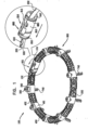
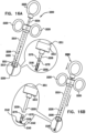
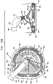
- FIG. 1 is a schematic illustration of an annuloplasty structure 100, e.g., at least one elongate segment or tubular element, comprising a plurality of compressible subunits 450 and a plurality of anchor mounts 461.
- Structure 100 comprises a modular annuloplasty structure in which the plurality of compressible subunits 450 are alternately disposed with respect to the plurality of anchor mounts 461.
- structure 100 comprises an implant shaped to define a tubular structure having a cross-section of any suitable shape, e.g., circular or elliptical.
- Compressible subunits 450 are shaped to define a hollow lumen and comprise a braided mesh 452 (e.g., wire or polyester), by way of illustration and not limitation.
- compressible subunits 450 may comprise a plurality of coils, braided structures, stent-shaped struts, or accordion- or bellows-shaped structures.
- a ratchet mechanism 600 (described hereinbelow with reference to Figs. 6A-B ) is disposed within the hollow lumen of structure 100.
- Ratchet mechanism 600 comprises a ratchet body 202 having a fixed end 210 and a dynamic end 220.
- ratchet mechanism 600 is shown as being used in combination with structure 100, it is to be noted that any of the ratchet mechanisms described herein may be used in combination with structure 100.
- compressible subunits 450 and anchor mounts 461 comprise a biocompatible material, e.g., nitinol, ePTFE, PTFE, stainless steel, platinum iridium, titanium, or cobalt chrome.
- compressible subunits 450 and anchor mounts 461 are coated with PTFE (Polytetrafluoroethylene).
- compressible subunits 450 function as accordion- or bellows-shaped compressible structures which facilitate proper cinching of the annulus when structure 100 is contracted. The configuration of the annulus of the mitral valve differs from patient to patient.
- Compressible subunits 450 when compressed, e.g., typically along a longitudinal axis of structure 100, enable respective portions of annuloplasty structure 100 to independently conform to the configuration of each portion of the annulus that is in alignment with a given portion of the annuloplasty structure.
- annuloplasty structure 100 is shaped to define a single tubular structure independently of the plurality of anchor mounts 461.
- the single tubular structure comprises an elongate sheath of compressible material, as described hereinabove with respect to compressible subunits 450.
- a contracting wire (not shown) is disposed within the lumen of structure 100 generally alongside ratchet body 202.
- pulling on the contracting wire controls the structural configuration of ratchet body 202 which in turn controls the structural configuration of structure 100, as will be described hereinbelow.
- an inward radial force is applied to structure 100, and a perimeter of structure 100 is modulated, i.e., reduced.
- the contracting wire comprises a flexible and/or superelastic material, e.g., nitinol, polyester, PTFE, ePTFE, stainless steel, or cobalt chrome, and is configured to reside chronically within structure 100.
- the contracting wire comprises a braided polyester suture (e.g., Ticron).
- the contracting wire is coated with polytetrafluoroethylene (PTFE).
- the contracting wire comprises a plurality of wires that are intertwined to form a rope structure.
- structure 100 is shaped to provide at least one longitudinal lumen for passage therethrough of ratchet body 202 and the contracting wire. In some embodiments, structure 100 is shaped to provide a first longitudinal lumen passage therethrough of the contracting wire and a second longitudinal lumen for passage therethrough of ratchet body 202.
- Ratchet body 202 is shaped to define a plurality of first engaging structures, e.g., first grooves 620, which are engageable by a tooth 612 of housing 610.
- grooves 620 are engaged by a second engaging structure, e.g., tooth 612, thereby allowing ratchet body 202 to slide in only one direction, i.e., the direction in which dynamic end 220 is first fed through housing 610 and as indicated by the arrow.
- a second engaging structure e.g., tooth 612
- Each anchor mount 461 is shaped to provide at least one longitudinal anchor mount lumen having an axis that is parallel with the longitudinal axis of the annuloplasty structure.
- the anchor mount lumen facilitates passage therethrough of ratchet body 202 and the contracting wire.
- each anchor mount 461 is shaped to provide a first longitudinal lumen passage therethrough of the contracting wire and a second longitudinal lumen for passage therethrough of ratchet body 202.
- Each anchor mount 461 is shaped to provide an anchor channel for passage therethrough of a helical anchor 740.
- the channel is shaped to define a lumen having a channel axis that is disposed at a non-zero angle, e.g., transverse, with respect to a longitudinal axis of the longitudinal lumen of the anchor mount through which ratchet body 202 and the contracting wire pass.
- the angle of the anchor channel with respect to the longitudinal lumen of anchor mount 461 facilitates corkscrewing of the anchor into the annulus of the valve of the patient at an angle as defined by the intersecting axes of the anchor channel and the longitudinal lumen of mount 461, as described hereinbelow with reference to Fig. 8 .
- annuloplasty structure 100 comprises a plurality of anchor mounts 461
- the respective angles defined by the intersecting axes of each anchor channel with the respective axis of the longitudinal lumen of each mount 461 is identical for all mounts 461.
- a first portion of the plurality of anchor mounts 461 has an angle that differs from the angle of a second portion of the plurality of anchor mounts.
- a portion of anchor mounts 461 designated to be anchored to the anterior portion of the annulus has an angle that is different from a portion of anchor mounts 461 designated to be anchored to the posterior portion of the annulus.
- the anchors may be anchored to different portions of the annulus at different angles in response to a need therefor.
- helical anchors 740 are used in combination with structure 100, any anchor described herein may be used in combination with structure 100.
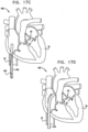
- structure 100 is advanced toward the valve in a closed configuration (e.g., substantially ring-shaped or "D"-shaped), as shown. It is to be noted that structure 100 may be advanced toward the valve of the patient in a linear configuration during an open-heart or minimally-invasive valve repair procedure.
- the contracting wire (not shown) is pulled and first and second ends 102 and 104 of annuloplasty structure 100 are drawn toward each other such that structure 100 assumes its closed configuration.
- structure 100 is manufactured having a first end 102 that is typically coupled to, e.g., welded to, housing 610 and a second end 104 that is not coupled to housing 610 during the advancing.
- structure 100 in such an embodiment, is advanced toward the left atrium of the patient in a generally linear configuration thereof.
- second end 104 is coupled to an engaging structure configured to engage housing 610 as structure 100 is made to assume its closed configuration.
- the engaging structure coupled to second end 104 comprises a tube having a diameter that is smaller than an inner diameter of housing 610 and is configured to slide within housing 610 as structure 100 is drawn into its closed configuration.
- Housing 610 comprises first and second coupling sites 650 and 660, for coupling of first end 102 and second end 104 of structure 100, respectively, to housing 610.
- annuloplasty structure 100 may be used independently of ratchet mechanism 600.
- annuloplasty structure 100 may comprise only the contracting wire passing through the lumen of structure 100.
- the respective ends of the contracting wire are: (1) pulled such that the annuloplasty structure assumes its closed configuration, and (2) locked together in order to maintain the closed configuration.
- structure 100 typically comprises a braided mesh in embodiments in which sutures pass through structure 100 and facilitate anchoring or suturing of structure 100 to the annulus.
- the mesh facilitates suturing of structure 100 to the annulus of the patient.
- the physician passes the suture through the mesh at a first location thereof, through tissue of the annulus, and subsequently, through a second location of the mesh, thereby suturing structure 100 to the annulus.
- the suturing is performed following placement of the annuloplasty structure along the annulus.
- a plurality of sutures are sutured to the annulus of the patient and the annuloplasty structure is slid along the sutures and toward the annulus.
- respective ends of each of the plurality of sutures are threaded through the mesh prior to the sliding, and are knotted together and clipped following the sliding. The knotting of the sutures maintains the positioning of the annuloplasty structure along the annulus.
- the mesh facilitates anchoring of the annuloplasty structure to the annulus of the patient.
- the physician passes the anchor through the mesh at a first location thereof and then through tissue of the annulus.
- the braided mesh may be used independently of or in combination with the compressible subunits and/or with the anchor mounts.
- the mesh may surround at least compressible subunits 450 of structure 100.
- the braided mesh may be used independently of compressible subunits 450 and/or anchor mounts 461.
- structure 100 may comprise only ratchet mechanism 600 and/or the contracting wire surrounded by a sheath of braided mesh.
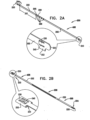
- ratchet mechanism 200 is used in combination with annuloplasty structure 100 as described hereinabove with reference to Fig. 1 . It is to be noted that ratchet mechanism 200 may be used in combination with any of the annuloplasty structures described herein.
- Ratchet mechanism 200 comprises a ratchet body 202 defining a flat ribbon having a proximal fixed end 210 and a distal dynamic end 220.
- Fig. 1 shows ratchet mechanism 600 disposed within annuloplasty structure 100, it is to be noted that ratchet mechanism 200 may be disposed within annuloplasty structure 100.
- Ratchet mechanism 200 is disposed within the lumen of structure 100 such that fixed end 210 is disposed within the lumen of structure 100 in the vicinity of first end 102 thereof, and dynamic end 220 is disposed within the lumen of structure 100 in the vicinity of second end 104 thereof.
- structure 100 is advanced toward the left atrium of the patient in a generally linear configuration.
- ratchet body 202 is shown in a linear configuration, it is to be noted that ratchet body 202 is later drawn into a closed configuration (e.g., substantially ring-shaped or "D"-shaped configuration) simultaneously with structure 100 assuming its closed configuration (e.g., substantially ring-shaped or "D"-shaped configuration).
- a closed configuration e.g., substantially ring-shaped or "D"-shaped configuration
- dynamic end 220 is advanced past fixed end 210 such that ratchet body 202 assumes its closed configuration as well.
- Dynamic end 220 and fixed end 210 are able to meet each other due to the sliding of ratchet body 200 along a track within the a respective lumen of each anchor mount 461 of structure 100, as will be described hereinbelow.
- Ratchet body 202 is shaped to define a plurality, e.g., at least two as shown, of first engaging structures, e.g., first windows 204, in the vicinity of dynamic end 220 and a plurality of second windows 206 in the general vicinity of the middle of ratchet body 202. It is to be noted that the number of second windows 206 is shown by way of illustration and not limitation.
- Fixed end 210 is shaped to define a second engaging structure, e.g., a tooth 230, which projects angularly away from a longitudinal axis of ratchet body 202 and is configured to engage the first engaging structures, e.g., windows 204 and 206.
- Fixed end 210 is shaped to define a slit 240 surrounding tooth 230. As ratchet mechanism 200 is initially drawn into its closed configuration, dynamic end 220 slides alongside tooth 230 and slit 240 of fixed end 210.
- Ratchet body 202 provides a portion 222 disposed between first windows 204 and second windows 206.
- portion 222 provides a smooth surface for unobstructed back and forth sliding of dynamic end 220 past fixed end 210 and enables the physician to adjust the size/perimeter of the annuloplasty structure before it is positioned along the annulus. Additionally, portion 222 enables the physician to adjust the size/perimeter of the ratchet mechanism 200 prior to being locked in place in response to the engaging of second windows 206 by tooth 230.
- portion 222 has a distance Di3 that is between 30 mm and 70 mm, e.g., 50 mm.
- ratchet mechanism 200 is typically disposed alongside the portion of contracting wire 110 which is disposed within the lumen of structure 100.
- dynamic end 220 is pulled toward fixed end 210.
- Dynamic end 220 is passively advanced alongside fixed end 210 due to the compression force applied by structure 100 in response to the pulling of contracting wire 110. That is, dynamic end 220 is not pulled by contracting wire 110, rather it is passively pushed in response to the pulling of wire 110.
- wire 110 is aligned alongside an external surface of ratchet body 202 and at an external perimeter thereof.
- contracting wire 110 pushes against the external surface of ratchet body 202 and applies a compression force thereto. Responsively to the compression force of wire 110 on the external surface of ratchet body 202, ratchet body 202 passively compresses. Further additional pulling of wire 110 reduces the perimeter of ratchet mechanism 200, and thereby of structure 100.
- structure 100 In response to continued pulling of contracting wire 110, structure 100 radially contracts and, in turn, applies an additional compression force to ratchet mechanism 200.
- ratchet body 202 In response to the compression force to the ratchet mechanism by structure 100, ratchet body 202 radially contracts as dynamic end 220 is passively slid further distally away from fixed end 210 thereby drawing second windows 206 closer toward tooth 230 of fixed end 210.
- Dynamic end 220 is slid distally away from fixed end 210 until tooth 230 engages a first window 208 of second windows 206. Tooth 230 remains locked in position with respect to first window 208 until an additional compression force is applied to ratchet body 202 in response to additional pulling of contracting wire 110.
- dynamic end 220 is shaped to define one or more holes configured for looping of contracting wire 110 therethrough.
- dynamic end 220 is pulled in response to tensile force applied to contracting wire 110 as it is pulled. Additional force applied to wire 110 pulls ratchet mechanism 200 into a closed configuration, e.g., a substantially ring-shaped configuration.
- structure 100 For embodiments in which structure is advanced toward the left atrium in its closed configuration, prior to the advancing, the physician forms structure 100 into a closed configuration by advancing dynamic end 220 beyond fixed end 210 until first windows 204 are in alignment with tooth 230 and ratchet body 202 locks in place.
- structure 100 defines a generally ring-shaped structure having a relatively large perimeter.
- the physician pulls wire 110 and dynamic end 220 slides and is pushed further away from fixed end 210 until second windows 206 lock and maintain a reduced perimeter of ratchet body 202, and thereby, structure 100.
- the plurality of second windows 206 are provided such that ratchet body 202, and thereby structure 100, can lock in place and maintain respective ratcheted perimeters thereof.
- the length of ratchet mechanism 200 in its linear configuration, the locking mechanism of ratchet mechanism 200, and compressible subunits 450 described hereinabove are provided so as to enable annuloplasty structure 100 to accommodate various sizes of dilated annuli of given patients.
- ratchet mechanism 200 facilitates: (1) positioning and anchoring structure 100 along the dilated annulus while body 202 (and thereby structure 100) has a first perimeter thereof, (2) contracting the dilated annulus in response to the contracting of body 202 (and thereby structure 100), and (3) maintaining the contracted state of the annulus while body 202 (and thereby structure 100) has a second perimeter thereof that is typically smaller than the first perimeter.
- ratchet mechanism 200 is described herein as being used in combination with structure 100 by way of illustration and not limitation.
- ratchet mechanism 200 may be surrounded by a tubular sheath comprising a braided mesh, e.g., metal or fabric such as polyester.
- the braided mesh facilitates passage of sutures or longitudinal guide members through the sheath in order to anchor or suture the sheath to the annulus.
- the braided mesh is longitudinally pulled such that the mesh decreases in diameter, i.e., the transverse cross-sectional diameter that is perpendicular with respect to the longitudinal axis of structure 100.
- the mesh is compressed such that the diameter of the mesh closely resembles the diameter of the mesh in its relaxed state.
- Fig. 2B shows ratchet mechanism 200 as described hereinabove with respect to Fig. 2A , with the exception that fixed end 210 is shaped to define a housing 250.
- housing 250 of fixed end 210 is shaped to define tooth 230 and slit 240 and is configured to receive dynamic end 220 in a manner as described hereinabove with respect to Fig. 2A .
- housing 250 is configured to provide stability to mechanism 200 during the aligning of windows 204 and 206 with tooth 230 of fixed end 210.
- ratchet body 202 assumes a closed configuration as dynamic end 220 is initially locked in place when tooth 230 of housing 250 engages first windows 204.
- a compression force is further applied to ratchet body 202 (e.g., a radial force or a tensile force applied in response to pulling the contracting wire, as described hereinabove) which further advances dynamic end 220 away from housing 250.
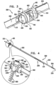
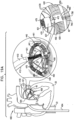
- Fig. 3 shows a system 300 comprising ratchet body 202 passing through a first one of anchor mounts 461 of annuloplasty structure 100.
- Anchor mount 461 comprises a lateral-aperture anchor mount 341 which comprises a substantially hollow, tubular element 463 configured for passage therethrough of ratchet body 202 and contracting wire 110.
- the anchor mount shown is configured to fix in place fixed end 210 of ratchet body 202. It is to be noted that anchor mount 341 may fix in place any of the ratchet bodies described herein.
- anchor mount 341 is shaped to define an aperture 340 configured for passage therethrough of an anchor, as will be described hereinbelow.
- a tubular channel (configuration shown hereinbelow with reference to Fig.
- aperture 340 is provided at a location along mount 461 such that passage of a tissue anchor therethrough (e.g., directly or indirectly through a channel coupled to portions of mount 341 defining aperture 340), does not interfere with contracting wire 110 and/or ratchet body 202 disposed within the annuloplasty structure.
- ratchet mechanism 200 may be coupled to a plurality of anchor mounts 341 which are disposed at various sites with respect to ratchet body 202.
- a respective compressible subunit 450 may be coupled to either end of anchor mount 341.
- anchor mount 461 is shaped to define a first coupling site 302 and a second coupling site 304.
- a respective compressible subunit 450 is coupled to coupling sites 302 and 304.
- Fig. 4 is a schematic illustration of system 300 comprising a tissue anchor 360 coupled to anchor mount 341.
- Anchor mount 341 fixes in place fixed end 210 of ratchet body 202 as described herein.
- Ratchet body 202 of Fig. 3 is shown in an open, linear configuration thereof, i.e., dynamic end 220 is not aligned alongside fixed end 210.
- An anchor 360 is shown coupled to mount 461.
- a tube-channel 1200 (as described in more detail hereinbelow with reference to Fig. 11 ) is coupled to mount 461 portions of mount 341 defining aperture 340.
- channel 1200 is welded to mount 461 during the manufacturing of mount 341.
- tube-channel 1200 is not welded to mount 341 but rather is advanced toward mount 341 together with, e.g., surrounding, anchor 360. In such an embodiment, channel 1200 is free to rotate with respect to aperture 340 along the longitudinal axis of mount 341.
- anchor 360 is shaped to define a helix having a pointed distal end 370 which punctures through tissue of the annulus of the heart.
- a helical anchor is shown by way of illustration and not limitation, and that any suitable anchor may be used to anchor the annuloplasty structure to the annulus.
- tube-channel 1200 may comprise a bar, as described in US Provisional Patent Application 61/001,013 , PCT Patent Application PCT/II,07/001503 , and US Patent Application 11/950,930 to Gross et al. , entitled, "Segmented ring placement".
- This bar is configured to restrict continued corkscrewing of helical anchor 360 into the tissue of the annulus beyond a predetermined distance, e.g., between 3 mm and 10 mm. Additionally, the bar functions as a nut providing a thread for the helical anchor to be advanced distally and corkscrewed around the bar and into the tissue of the annulus.
- helical anchor 360 is coupled at a proximal end thereof (i.e., the portion of anchor 360 that is not configured to be advanced into the annulus tissue) to a head portion 380.
- a distal end of head portion 380 has a diameter that is larger than a diameter of tube-channel 1200.
- head portion 380 is shaped to define one or more, e.g., two as shown, engaging elements, e.g., holes, 390.
- engaging elements 390 are configured for coupling and/or passage therethrough of an actuation means by way of illustration and not limitation, and the anchoring means is configured to corkscrew the anchor into the tissue of the annulus.
- engaging elements 390 are shown as being circular by way of illustration and not limitation, and that elements 390 may be shaped to define any suitable shape, e.g., rectangles, ovals, etc.
- head portion 380 prevents continued distal motion of anchor 360 into the annulus with respect to the distal surface of the anchor mount, i.e., the portion of the mount designated to align with and contact the annulus.
- the tube-channel 1200 rotates within aperture 340 along the longitudinal axis of mount 461 together with the rotating of anchor 360.
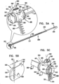
- anchor mount 461 comprises a transverse-lumen anchor mount 342 comprising a tubular element 465 shaped to define an anchor lumen 501 having an longitudinal axis 502 thereof.
- Tubular element 465 fixes in place fixed end 210 of ratchet body 202 as described hereinabove with reference to Fig. 2A .
- anchor mount 461 provides at least one longitudinal anchor mount lumen having an axis that is parallel with the longitudinal axis of the annuloplasty structure. Anchor mount lumen facilitates passage therethrough of ratchet mechanism 200 and contracting wire 110.
- Longitudinal axis 502 of anchor lumen 501 is at a non-zero angle, e.g., transverse, with respect to the longitudinal axis of the anchor mount lumen of anchor mount 461.
- Transverse lumen 501 is shaped to facilitate passage therethrough of tube-channel 1200, as described hereinabove with reference to Fig. 4 . As shown, transverse lumen 501 does not interfere with ratchet body 202 and contracting wire 110.
- Anchor mount 461 is coupled at either end thereof to a respective stabilizing structure 310.
- Stabilizing structure 310 is shaped to define mounts 312 which are configured to surround and lock in place a portion of anchor mount 461 and to prevent swiveling thereof.
- Ratchet body 202 passes through aperture 330 of stabilizing structure 310 and through the longitudinal anchor mount lumen. Passing of ratchet body 202 through structure 310 and then through mount 461 locks in place stabilizing structure 310 which, in turn, locks in place anchor mount 461 and prevents it from pivoting laterally.
- aperture 330 of stabilizing structure 310 provides a suitable track for advancement of ratchet body 202 along a defined path. For example, this track enables the proper positioning of dynamic end 220 with respect to fixed end 210.
- aperture 330 has a major axis 331 and has a longitudinal axis 332 that is transverse with respect to major axis 331.
- Major axis 331 of aperture 330 is typically disposed at a non-zero angle with respect to axis 502 of anchor lumen 501.
- a portion of ratchet body 202 passes through aperture 330 along longitudinal axis 332 thereof.
- ratchet body 202 passes through aperture 330 of a first stabilizing structure 310, through the lumen of anchor mount 461, and subsequently through aperture 330 of a second stabilizing structure 310.
- mount 461, and thereby lumen 501 Prior to the coupling of mount 461 to a pair of structures 310, mount 461, and thereby lumen 501, is allowed to pivot laterally. Following the coupling of structures 310 to mount 461, structures 310 restrict the lateral pivoting of mount 461.
- aperture 330 is created such that major axis 331 is disposed at a desired angle with respect to axis 502 of anchor lumen 501 when coupled to mount 461.
- a portion of ratchet body 202 is then passed through mount 461 and subsequently through aperture 330, thereby fixing the angle of the major axis of aperture 330 with respect to axis 502 of anchor lumen 501.
- longitudinal axis 332 of aperture 330 is substantially parallel with respect to a plane of the annulus and parallel with the longitudinal axis of the annuloplasty structure, and
- axis 502 of anchor lumen 501 is at a non-zero angle with respect to major axis 331 of the aperture 330.
- the angle of anchor lumen 501 with respect to longitudinal axis 332 facilitates corkscrewing of the tissue anchor into the annulus at an angle as defined by the intersecting axes 502 of lumen 501 and major axis 331 of aperture 330 (shown in Fig. 5C ).
- a first pair of structures 310 may be shaped to define apertures 330 having a major axis at a first desired angle with respect to axis 502 of anchor lumen 501 of a first anchor mount 461
- a second pair of structures 310 may be shaped to define apertures 330 having a major axis at a second desired angle with respect to the longitudinal axis of anchor lumen 501 of a second anchor mount 461.
- the respective anchors configured to be passed through each of the first and second anchor mounts are anchored to the tissue at the desired first and second angles, respectively.
- the anchors which pass through the anchor mounts positioned along the annulus in alignment with the base of the posterolateral leaflet may be anchored at an angle that is different from an angle at which the anchors which pass through the anchor mounts positioned along the annulus in alignment with the base of the anteromedial leaflet are anchored.
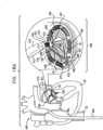
- Fig. 5C shows a perspective view of system 300 from an opposite view than that shown in Fig. 5A .
- Ratchet body 202 passes unobstructed alongside anchor lumen 501 of anchor mount 461.
- anchor mount 461 may also function as a housing for fixed end 210 of ratchet body 202.
- Anchor mount 461 is shaped to define a slit 520 which engages and fixes in place a portion 212 of fixed end 210. Typically, portion 212 projects away perpendicularly from a longitudinal axis of ratchet body 202.
- FIG. 5B shows a stabilizing unit 500 having a stabilizing structure 310 is shaped to define: (1) a hole 320 configured for passage therethrough of contracting wire 110, and (2) a longitudinal aperture 330 configured for passage therethrough of ratchet body 202.
- aperture 330 has a width L7 of between 0.3 mm and 0.8 mm. Such a width facilitates passage therethrough of at least a portion of ratchet body 202.
- width L7 accommodates for the widths of both the first and second portions of ratchet body 202 and facilitates passage therethrough of both portions.
- Fig. 3 shows ratchet body 202 in a closed configuration thereof. It is to be noted that ratchet body 202 assumes a substantially circular configuration thereof and that only a portion of ratchet body 202 is shown.
- dynamic end 220 is passively fed through aperture 330 alongside fixed end 210. As such, a portion of body 202 distal to fixed end 210 aligns alongside a portion proximal to dynamic end 220, as shown in Fig. 3 .
- width L7 of aperture 330 accommodates for the widths of (1) the portion of body 202 distal to fixed end 210, and (2) the portion of body 202 proximal to dynamic end 220.
- Ratchet body 202 is shaped to define dynamic distal end 220 and fixed proximal end 210. As shown, ratchet body 202 is shaped to define a plurality of first engaging structures, e.g., grooves 622, configured to be engaged by a second engaging structure, a tooth 612, at fixed end 210. Fixed end 210 is coupled to a substantially tubular ratchet-coupling housing 610 which is shaped to define a first coupling site 650 and a second coupling site 660. For embodiments in which ratchet mechanism 600 is used in combination with compressible subunits 450 as described hereinabove with reference to Fig. 1 , a respective compressible subunit 450 is coupled to coupling sites 650 and 660.
- first engaging structures e.g., grooves 622
- Fixed end 210 is coupled to a substantially tubular ratchet-coupling housing 610 which is shaped to define a first coupling site 650 and a second coupling site 660.
- ratchet mechanism 600 is disposed within the lumen of structure 100 such that fixed end 210 is disposed within the lumen of structure 100 in the vicinity of first end 102 thereof and dynamic end 220 is disposed within the lumen of structure 100 in the vicinity of second end 104 thereof.
- ratchet body 202 is shown in a linear configuration, it is to be noted that ratchet body 202 is drawn into its closed configuration simultaneously with structure 100 assuming its closed configuration.
- dynamic end 220 is fed into housing 610 and is advanced past fixed end 210 such that ratchet body 202 assumes its closed configuration as well.
- dynamic end 220 and the portion of body 202 that is proximal to end 220 are slid alongside fixed end 210 and the portion of body 202 that is distal to fixed end 210.
- housing 610 is coupled to an insert 640 that is shaped to define a longitudinal track 642.
- dynamic end 220 and fixed end 210 are able to meet each other due to the sliding dynamic end 220 along track 642 within the lumen housing 610.
- Ratchet body 202 is shaped to define a plurality, e.g., at least two as shown, of first grooves 620 in the vicinity of dynamic end 220 and a plurality of second grooves 630 in the general vicinity of the middle of ratchet body 202. It is to be noted that the respective numbers of first grooves 620 and second grooves 630 are shown by way of illustration and not limitation. As ratchet mechanism 600 is initially drawn into its closed configuration, dynamic end 220 slides alongside track 642 and tooth 612 engages respective grooves 622 of ratchet body 202.
- Ratchet body 202 provides a portion 222 disposed between first grooves 620 and second grooves 630.
- portion 222 provides a smooth surface for unobstructed back and forth sliding through fixed end 210 and enables the physician to adjust the size/perimeter of the annuloplasty structure before it is positioned along the annulus. Additionally, portion 222 enables the physician to adjust the size/perimeter of ratchet mechanism 600 prior to the locking of second grooves 630 by tooth 612.
- portion 222 has a distance that is between 30 mm and 70 mm, e.g., 50 mm.
- ratchet mechanism 600 may be anchored to the annulus independently of annuloplasty structure 100 described hereinabove with reference to Fig. 1 and with reference to ratchet mechanism 200 described hereinabove with reference to Figs. 2A-B .
- ratchet mechanism 600 is typically disposed alongside the portion of contracting wire 110 which is disposed within the lumen of structure 100.
- dynamic end 220 is pulled toward fixed end 210.
- Dynamic end 220 is passively advanced within housing 610, typically alongside fixed end 210, due to the compression force applied by structure 100 in response to the pulling of contracting wire 110.
- structure 100 In response to continued pulling of contracting wire 110, structure 100 radially contracts and, in turn, applies an additional compression force to ratchet mechanism 600.
- ratchet body 202 In response to the compression force, ratchet body 202 radially contracts as dynamic end 220 is passively slid further distally away from fixed end 210 thereby drawing second grooves 630 closer toward tooth 612 of housing 610.
- Dynamic end 220 is slid distally away from fixed end 210 until tooth 612 engages a first groove 624 of second grooves 630. Tooth 612 remains locked in position with respect to first groove 624 until an additional compression force of structure 100 is applied to ratchet body 202 (i.e., in response to the pulling of contracting wire 110).
- dynamic end 220 is advanced past fixed end 210 until first grooves 620 are in alignment with tooth 612 and ratchet body 202 is locked in an expanded configuration thereof and has a relatively large perimeter.
- the dynamic end 220 is pushed further distally away (i.e., in the direction as indicated by the arrow in Fig. 6B ) from fixed end 210 until locking groves 630 lock and fix a perimeter of body 202, and thereby, fix a perimeter of structure 100.
- the plurality of second grooves 630 is provided such that ratchet body 202, and thereby structure 100, can lock in place and maintain respective ratcheted perimeters thereof.
- the length of ratchet mechanism 600 in its linear configuration, the locking mechanism of ratchet mechanism 600, and compressible subunits 450 described hereinabove are provided so as to enable annuloplasty structure 100 to accommodate various sizes of dilated annuli of given patients.
- ratchet mechanism 600 facilitates: (1) positioning and anchoring structure 100 along the dilated annulus while body 202 (and thereby structure 100) has a first perimeter thereof, (2) contracting the dilated annulus in response to the contracting of body 202 (and thereby structure 100), and (3) maintaining the contracted state of the annulus while body 202 (and thereby structure 100) has a second perimeter thereof that is typically smaller than the first perimeter.
- ratchet mechanism 600 is described as being used in combination with structure 100 by way of illustration and not limitation.
- ratchet mechanism 600 may be surrounded by a tubular sheath comprising a braided mesh, e.g., metal or fabric such as polyester.
- Fig. 6B shows dynamic end 220 having already passed through housing 610 of fixed end 210.
- ratchet body 202 assumes a closed configuration (partially shown for clarity of illustration).
- dynamic end 220 is shaped to define one or more holes 613 configured for looping of the contracting wire therethrough.
- dynamic end 220 is pushed in response to tensile force applied to the contracting wire as it is pulled.
- additional force applied to the contracting wire pushes ratchet mechanism 200 into a closed configuration, e.g., a substantially ring-shaped configuration. Further additional pulling of the contracting wire reduces the perimeter of ratchet mechanism 600, and thereby of the annuloplasty structure.
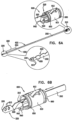
- Fig. 7 shows ratchet mechanism 600 as described hereinabove with reference to Figs. 6A-B , with the exception that housing 610 provides a tooth 712 is shaped to define a window 714. Tooth 712 is coupled to housing 610 along a junction and bends along the junction. As tooth 712 engages groove 620 of ratchet body 202, window 714 surrounds a portion 772 of an upper surface 770 of ratchet body 202 which defines groove 620. Window 714 thus enables tooth 712 to advance distally and bend as far as possible within groove 620 without being obstructed by portion 772 of upper surface 770 which defines groove 620.
- Tooth 712 engages groove 620 and locks ratchet body 202 in place until an additional inward, radial pushing force is applied thereto, e.g., typically, in response to the pulling of contracting wire 110 described herein.
- an additional inward, radial pushing force applied to ratchet body 202 (a) dynamic end 220 is slid further away from housing 610 in the same direction in which dynamic end 220 was initially fed into housing 610 (i.e., the direction as indicated by the arrow), and (b) tooth 712 slides along upper surface 770 of ratchet body 202 until tooth 712 engages another groove 620 of ratchet body 202.
- Dynamic end 220 is shaped to define one or more holes 613 configured for looping of the contracting wire therethrough.
- dynamic end 220 is pulled in response to tensile force applied to the contracting wire as it is pulled. Additional force applied to the contracting wire pulls ratchet mechanism 600 into the closed configuration. Further additional pulling of the contracting wire reduces the perimeter of ratchet mechanism 600, and thereby of the annuloplasty structure.
- ratchet body 202 may be pulled by contracting wire 110 in some embodiments. Ratchet body 202 is typically pushed in response to the radial, compressing force applied to body 202 by the annuloplasty structure in response to the pulling of contracting wire 110.
- Fixed end 210 of ratchet body 202 is shaped to define a protrusion 722 (not shown in Figs. 6A-B ).
- Housing 610 is shaped to define a slit (not shown for clarity of illustration) for passage therethrough of protrusion 722 in order to fix fixed end 210 in place with respect to housing 610.
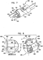
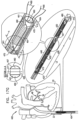
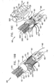
- Fig. 8 shows an anchor mount system 900 comprising an anchor mount 461 comprising a double-lumen anchor mount 343 that is shaped to define a channel 460 and a lumen 920, or channel.
- Anchor mount 461 is shaped to define a lateral wall 467 having a first portion 464 and a second portion 466 generally at opposite sites of mount 461 when viewed in cross-section (e.g., at 12 o'clock and 6 o'clock).
- first portion 464 is shaped to define an opening thereof
- second portion 466 is shaped to define an opening thereof.
- Channel 460 extends from the opening of first portion 464, through the anchor mount, to the opening in second portion 466.
- anchor mount 461 is configured for facilitating passage therethrough any anchor described herein in order to facilitate anchoring of an annuloplasty structure (e.g., any annuloplasty structure comprising mount system 900) to the annulus of the patient.
- Channel 460 has a diameter between about 0.8 mm and 2.5 mm, e.g., 1.8 mm, that is sized to facilitate passage therethrough of any one of the anchors, anchoring structures, or anchoring systems described herein.
- the anchors described herein are configured for passage through channel 460 have a diameter of between about 0.5 mm and 2.4 mm, e.g., 1.6 mm.
- First portion 464 of lateral wall 467 of mount 461 is shaped to define a tapered opening 950 above channel 460. Opening 950 has a diameter that is typically larger than a diameter D2 of channel 460.
- an anchor is coupled to an advancement structure, e.g., a tube or a rod, at a distal end thereof and is advanced via the advancement structure toward channel 460.
- a portion of the distal end of the advancement structure has a diameter that is slightly larger than the proximal end of channel 460, i.e., opening 950 of anchor mount 461.
- the advancement of the advancement structure is restricted from passage through channel 460 beyond the portion of the distal end of the tube that has a diameter larger than the diameter of channel 460. This restriction helps ensure that the anchor is not advanced too deeply within tissue of the annulus.
- a proximal portion (e.g., the portion of the anchor that is coupled to the distal end of the advancement structure) of the anchor is configured to expand.
- the proximal portion of the anchor is compressed within an overtube during the advancement of the anchor toward the annulus of the valve.
- the overtube is slid proximally from the proximal end of the anchor and the proximal portion is allowed to expand.
- the expanded portion of the anchor has a diameter that is (a) larger than diameter D2 of channel 460 and (b) smaller than the diameter at the distal end of opening 950.
- the expanded, proximal portion of the anchor rests within the proximal end of opening 950 and functions as a cap which restricts further distal advancement of the anchor into the tissue of the annulus.
- Anchor mount 461 is shaped to provide an anchor mount and ratchet body lumen 920 for passage of ratchet body 202 of any of the ratchet mechanisms described herein.
- Ratchet body lumen 920 has (a) a longitudinal axis 942 that is substantially parallel with respect to the plane of the annulus and parallel with the longitudinal axis of the annuloplasty structure, and (b) an axis 940 that is typically at a non-zero angle, e.g., transverse, with respect to longitudinal axis 942.
- Channel 460 has a first axis 930 is typically at a non-zero angle, e.g., transverse, with respect to longitudinal axis 942.
- lumen 920 is disposed with respect to channel 460 such that axis 940 of lumen 920 is disposed at an angle theta, with respect to axis 930 of channel 460.
- the anchor is anchored at angle theta with respect to axes 940 and 920 and the plane of the annulus of the valve. It is to be noted angle theta may range between 10 degrees and 70 degrees, typically 30 degrees.
- angle theta is identical for all mounts 461.
- a first portion of the plurality of anchor mount systems 900 has an angle theta that differs from the angle theta of a second portion of the plurality of anchor mount systems 900.
- a portion of anchor mount systems 900 designated to be anchored to the anterior portion of the annulus has an angle theta that is different from a portion of anchor mount systems 900 designated to be anchored to the posterior portion of the annulus.
- the anchors may be anchored to different portions of the annulus at different angles in response to a need therefor.
- the contracting wire described herein passes through lumen 920 alongside ratchet body 202.
- mount 461 of system 900 is shaped to provide an additional distinct lumen configured for passage therethrough of the contracting wire (configuration not shown).
- Anchor mount 461 comprises first and second coupling sites 960 and 970 configured for coupling, e.g., wrapping therearound or welding, respective ends of one or more compressible subunits 450 as described hereinabove.
- FIG. 9 shows an anchor mount system 1000 comprising an anchor mount 461 having a curved lateral surface 1100 that is coupled to an anchor channel 350 for passage of an anchor therethrough.
- Anchor mount 461 is configured for use in combination with any of the annuloplasty structures described herein.
- Mount 461 and is shaped to define a first lumen 1010 configured for passage therethrough of the contracting wire and a second lumen 1020 for passage therethrough of the ratchet body of any one of the ratchet mechanisms described herein.
- Lumens 1010 and 1020 facilitate unobstructed passage of the contracting wire and the ratchet body, respectively, with respect to the passage of an anchor through channel 350.
- lumen 1020 has a first axis 1022 and channel 350 has a second axis 1030 which is disposed at an angle theta (e.g., between 10 degrees and 70 degrees, typically 30 degrees) with respect to first axis 1022.
- the anchor passed through channel 350 is anchored to the annulus at angle theta with respect to the ratchet body disposed within lumen 1020.
- Anchor mount 461 comprises first and second coupling sites 1110 and 1112 configured for coupling, e.g., wrapping therearound or welding, respective ends of one or more compressible subunits 450 as described hereinabove.
- Fig. 10 shows an anchor mount system 1111 comprising an anchor mount 461 comprising lateral-aperture anchor mount 341 which is shaped to define an aperture 340 configured for passage therethrough of an anchor, as described hereinabove with reference to Fig. 3 .
- the anchor is slid through aperture 340 and rests against portions 1142 of mount 461 which define aperture 340.
- portions 1142 provide horizontal surfaces 1140 which function as shelves impeding continued distal motion of an anchor configured to be advanced through aperture 340.
- a channel for passage of the anchor is welded to mount 461 along portions 1142 of mount 461.
- the channel is advanced toward mount 461 together with the anchor. In such an embodiment, the channel is free to rotate with respect to aperture 340 along the longitudinal axis of mount 461.
- Anchor mount 461 comprises a substantially tubular element 463 which defines a longitudinal anchor mount lumen. Aperture 340 is created at a location of mount 461 such that passage of an anchor via aperture 340, directly or indirectly, does not interfere with the contracting wire and/or ratchet body disposed within the longitudinal lumen of mount 461.
- Anchor mount 461 also functions as a housing for fixed end 210 of ratchet body 202.
- Anchor mount 461 is shaped to define slit 520 which engages and locks portion 212 of fixed end 210.
- Anchor mount 461 comprises first and second coupling sites 112 and 114 configured for coupling, e.g., wrapping therearound or welding, respective ends of one or more compressible subunits 450.
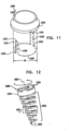
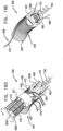
- Fig. 11 is a schematic illustration an anchor tube-channel 1200 configured to be used in combination with any one of anchor mounts 461 described herein.
- anchor channel 1200 is configured to be advanced through lumen 501 of anchor mount 461 shown in Figs. 5A and 5C .
- channel 1200 is welded to anchor mount 461, shown in Figs. 3, 4 , and 10 , via aperture 340.
- channel 1200 is welded via surface 1100 to anchor mount 461, shown in Fig. 9 , in place of channel 350.
- Channel 1200 has (a) a proximal end 1250 which provides a passageway for passage of an anchor through a channel 1210 of channel 1200, and (b) a distal end 1260 which typically rests against the annulus of the valve when the annuloplasty structure is positioned along the annulus.
- Proximal end 1250 of channel 1200 is shaped to define an external ring 1220 having a diameter larger than the diameter of proximal end 1250 of channel 1200.
- channel 1200 is configured to be advanced distally through lumen 501 of anchor mount 461 shown in Figs.
- ring 1220 functions to impede continued distal motion of channel 1200 beyond a predetermined depth, as limited by ring 1220 abutting a proximal opening of channel 501 of anchor mount 461.
- channel 1200 is free to rotate with respect to aperture 340 along the longitudinal axis of mount 461.
- Channel 1200 is shaped to define one or more (e.g., two, as shown) lateral slits 1230 and 1240.
- a longitudinal bar (not shown) is configured to be welded between slits 1230 and 1240.
- Slits 1230 and 1240 enable the bar to be welded to channel 1200 in any given configuration, e.g., substantially perpendicularly to or diagonally with respect to slits 1230 and 1240, and at any angle with respect to slits 1230 and 1240.
- a first end of the bar may be coupled to a portion of channel 1200 defining proximal end 1231 of slit 1230 while a second end of the bar is coupled to a portion of channel 1200 defining distal end 1242 of slit 1240, by way of illustration and not limitation.
- the first end of the bar may be coupled to proximal end 1231 of slit 1230 while the second end of the bar is coupled to a portion defining slit 1240 that is between proximal end 1241 and distal end 1242 thereof.
- the first and second ends of the bar may be coupled to: (1) proximal end 1231 of slit 1230 and proximal end 1241 of slit 1240, respectively, (2) distal end 1232 of slit 1230 and distal end 1242 of slit 1240, respectively, or (3) parallel portions of slits 1230 and 1240 that are between the respective distal and proximal ends of slits 1230 and 1240.
- the bar provides a reference force to help corkscrew the anchor into tissue of the annulus during the initial corkscrewing thereof.
- a predetermined distance e.g., a predetermined distance from that lateral surface of mount 461 which rests against tissue of the annulus
- the anchor is allowed to resume rotational motion together with rotational motion of channel 1200 for embodiments in which channel 1200 is not welded to anchor mount 461.
- this continued rotational motion draws tissue of the annulus toward the annuloplasty structure.
- Such proximal drawing of the tissue thereby minimizes and substantially eliminates the gap.
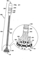
- Fig. 12 is a schematic illustration of an anchoring structure 1800 comprising a tapered, conical helical element 1802 comprising a plurality of coils 1810.
- the plurality of coils 1810 comprises a pointed distal end 1820 which punctures tissue of the annulus and allows for coils 1810 to be corkscrewed distally into the tissue of the annulus.
- a proximal surface of element 1802 is coupled to a head portion 1830 comprising raised surfaces 1832 having a defined conformation.
- head portion 1830 functions to prevent distal screwing of structure 1800 into the annulus of the patient beyond a predetermined depth as defined by the combined length of head portion 1830 and coils 1810.
- structure 1800 is not able to be advanced further distally, continued rotation of structure 1800 draws tissue proximally with respect to the annuloplasty structure, thereby substantially minimizing or eliminating a gap that may be created between the annuloplasty structure and the tissue of the annulus.
- an anchor advancement structure e.g., a tube or a rod, (not shown) is coupled at a distal end thereof to structure 1800 via raised surfaces 1832.
- the distal end of the advancement device is shaped to define recessed portions which are similar in shape to the define conformation of raised surfaces 1832.
- the advancement device is coupled to structure 1800 when the recessed portions of the device accommodate the conformation of raised surfaces 1832 by surrounding and locking in place surfaces 1832 with respect to the recessed portions of the advancement device.
- the advancement device is locked together with structure 1800 when a rotational force is applied to the advancement force in a rotational direction as indicated by the arrow.
- a rotational force is applied to the anchor advancement structure in a direction opposite to the direction indicated by the arrow which detaches the advancement device from structure 1800 by sliding the recessed portions of the advancement device away from raised structures 1832.
- the anchor advancement structure comprises an advancement structure, e.g., a tube or a rod, which is typically coupled to head portion 1830 prior to being transcatheterally advanced toward the annuloplasty structure.
- an external anchoring device e.g., an advancement tube, an advancement rod, or a screw-driving system
- an external anchoring device is used in order to facilitate anchoring of structure 1800 to the annulus.
- the anchor advancement structure advances the anchor toward the annuloplasty structure, the anchor advancement structure is rotated in order to facilitate corkscrewing of anchoring structure 1800 into the annulus of the patient.
- structure 1800 may be advanced through the mesh and anchor the annuloplasty structure to the annulus via the mesh.
- the compressible subunits of the annuloplasty structure comprise a coiled structure
- coils 1810 of structure 1800 are coiled around a portion of coils of the coiled compressible subunits of the annuloplasty structure and subsequently through the tissue of the annulus of the patient.
- a longitudinal axis 1801 of structure 1800 is at a non-zero angle, e.g., perpendicular, with respect to a longitudinal axis of the annuloplasty structure.
- Such intercoiling of coils 1810 with the coils of the coiled compressible subunits of the annuloplasty structure facilitates the coupling of the annuloplasty structure with anchoring structure 1800 during the corkscrewing of structure 1800 into the tissue of the annulus.
- annuloplasty structure 1800 comprises at least one anchor mount, as described hereinabove, structure 1800 is advanced through the anchor mount and into the annulus of the patient.
- head portion 1830 has a diameter that is larger than the inner diameter of lumen 501 of anchor mount 461. As anchoring structure 1800 is advanced through lumen 501, a distal surface of head portion 1830 abuts a proximal opening of lumen 501 and inhibits continued distal motion of structure 1800 through the tissue of the annulus beyond the predetermined depth.
- the diameter of head portion 1830 is larger than diameter D2 of channel 460 defined by anchor mount 461. As structure 1800 is advanced through channel 460, the distal surface of head portion 1830 abuts proximal opening 950 and inhibits continued distal motion of structure 1800 through the tissue of the annulus beyond the predetermined depth.
- the diameter of head portion 1830 is larger than the inner diameter of channel 350 coupled to anchor mount 461. As structure 1800 is advanced through channel 350, the distal surface of head portion 1830 abuts a proximal opening of channel 350 and inhibits continued distal motion of coils 1810 through the tissue of the annulus beyond the predetermined distance.
- Figs. 10 and 12 As structure 1800 is advanced through channel 350, the distal surface of head portion 1830 abuts horizontal surfaces 1140 defining aperture 340 and inhibits continued distal motion of coils 1810 through the tissue of the annulus beyond the predetermined distance.
- Figs. 11 and 12 As structure 1800 is advanced through channel 1210 of channel 1200, the distal surface of head portion 1830 abuts proximal end 1250 of channel 1200 and inhibits continued distal motion of coils 1810 through the tissue of the annulus.
- the proximal coil of helical element 1802 has a diameter that is larger than the diameter of the distal coil of element 1802.
- the diameters of the coils of helical element 1802 are gradually reduced in each successive coil from the proximal coil to the distal coil.
- the distal coil is corkscrewed into the tissue of the annulus following the puncturing of the annulus by pointed distal end 1820. As the distal coil is corkscrewed distally through the tissue of the annulus, the distal coil pushes against the surrounding tissue, thereby exerting a radial force against surrounding tissue of the annulus.
- Each successive proximal coil of helical element 1802 enters an opening defined by the distal coil adjacent thereto.
- the diameter of the opening is smaller than the diameter of the successive proximal coil.
- each successive proximal coil of exerts an outward, radial force on surrounding tissue corresponding to the diameter of successive proximal coil.
- the proximal coil exerts a greater force on the surrounding tissue than does the distal coil.
- the ratio between the diameter of the proximal coil to the diameter of the distal coil is shown by way of illustration and not limitation. For example, the ratio may be smaller than the ratio that appears in Fig. 12 .
- the proximal coil of helical element 1802 has a diameter that is smaller than the diameter of the distal coil of element 1802 (configuration not shown).
- the diameters of the coils of helical element 1802 are gradually increased in each successive coil from the proximal coil to the distal coil.
- the distal coil is corkscrewed into the tissue of the annulus following the puncturing of the annulus by pointed distal end 1820. As the distal coil is corkscrewed distally through the tissue of the annulus, the distal coil pushes against the surrounding tissue, thereby exerting a radial force against surrounding tissue of the annulus.
- Each successive proximal coil of the helical element enters an opening defined by the distal coil adjacent thereto.
- each successive proximal coil of exerts an inward, radial force on tissue disposed within the lumen of the successive proximal coil corresponding to the diameter of the successive coil.
- the proximal coil exerts a greater force tissue disposed within the lumen defined by helical element 1802 than does the distal coil.
- each coil of helical element 1802 exerts an inward, radial force on tissue disposed within a lumen of helical element 1802 corresponding to the diameter of each respective coil.
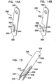
- Figs. 13A-B show an anchor 1900 comprising a distal barb 1930 and body portion 1910 which assume first and second configurations, respectively.
- Anchor 1900 has a proximal end 1920 and a distal pointed tip 1940 that punctures tissue of the patient.
- Body portion 1910 is shaped to define a narrow distal portion 1950 which is proximal to distal barb 1930.
- anchor 1900 comprises a shape-memory alloy, e.g., nitinol, which enables structure to transition between the configuration shown in Fig. 13A to the configuration shown in Fig. 13B .
- anchor 1900 During advancement toward the cardiac tissue, anchor 1900 is typically surrounded by an overtube (not shown) which maintains anchor 1900 in a generally straight configuration (shown in Fig. 13A ). A distal end of the overtube contacts tissue of the patient and anchor 1900 is slightly pushed distally so that barb 1930 emerges from within the tube and is able to puncture the tissue. Anchor 1900 is further pushed distally from within the overtube such that anchor 1900 further penetrates the tissue and is allowed to gradually assume its resting configuration (i.e., the configuration anchor 1900 has a tendency to assume, as shown in Fig. 13B ) commensurate with the extent of distal pushing of anchor 1900.
- anchor 1900 is initially passed through the mesh prior to being advanced through the tissue of the patient.
- anchor 1900 anchors itself to the annuloplasty structure by being entwined by the mesh.
- anchor 1900 is advanced through, and in some embodiments, coupled to, anchor mounts 461 described herein.
- anchor 1900 assumes its bent configuration (shown in Fig. 13B )
- the proximal bending of body 1910 pushes proximally tissue of the annulus that is disposed between anchor 1900 and the annuloplasty structure positioned at the surface of the annulus.
- annulus tissue is pushed proximally toward the annuloplasty structure.
- the proximal pushing of the annulus tissue toward the annuloplasty structure in response to the bending of anchor 1900 substantially minimizes or eliminates the gap.
- Figs. 13C-D show anchor 1900 as described hereinabove with reference to Figs 13A-B with the exception that body 1910 is not shaped to provide narrow distal portion 1950.
- Fig. 13E is a cross-sectional illustration of anchor 1900 anchored within tissue 1960.
- the annuloplasty structure is positioned at a surface 1962 of tissue 1960.
- proximal end 1920 is coupled to (e.g., disposed within) the annuloplasty structure at a first location thereof
- body portion 1910 of anchor 1900 is disposed within tissue 1960 in a "U"-shaped configuration thereof
- distal barb 1930 is exposed from within tissue 1960 and is coupled to the annuloplasty structure at a second location thereof.
- barb 1930 is first passed through the braided mesh at the first location of the annuloplasty structure, through tissue 1960, then through the braided mesh at the second location of the annuloplasty structure, thereby anchoring the structure to the annulus while additionally coupling anchor 1900 to the annuloplasty structure.
- Figs. 14A-B which are schematic illustrations of an anchor 2000 having a substantially rigid body portion 2010, a distal pointed tip 2032, and a flap 2050 proximal to distal tip 2032 which assume first and second positions, respectively.
- Body portion 2010 has a proximal end 2020 and is shaped to define a slit 2040 between a distal portion of body 2010 and flap 2050. Slit 2040 enables flap 2050 to transition between the configuration of flap 2050 shown in Fig. 14A to the configuration of flap 2050 shown in Fig. 14B .
- anchor 2000 comprises a shape-memory alloy, e.g., nitinol, which enables flap 2050 to transition along a junction 2030 between flap 2050 and body portion 2010 between the configuration shown in Fig. 14A to its resting configuration (i.e., the configuration flap has a tendency to assume, as shown in Fig. 14B ).
- a shape-memory alloy e.g., nitinol
- Anchor 2000 is typically surrounded by a sheath or sleeve (not shown) that is typically rectangular and defines a lumen for surrounding anchor 2000, and enables flap 2050 to maintain a generally straight configuration (shown in Fig. 14A ) as it is advanced toward the tissue of the patient.
- a distal end of the sheath contacts tissue of the patient and anchor 2000 is slightly pushed distally so that distal pointed end 2032 emerges from within the tube and is able to puncture the tissue.
- Anchor 2000 is further pushed distally from within the overtube such that anchor 2000 further penetrates the tissue. Structure is then distally advanced to a desired depth and is then pulled proximally enabling flap 2050 to gradually bend along junction 2030 away from a longitudinal axis of body portion 2010.
- Anchor 2000 assumes its relaxed, or bent, position (shown in Fig. 14B ) commensurate with the extent of proximal pulling of anchor 2000.
- a proximal end of flap 2050 is shaped to define a pointed tip 2052.
- tip 2052 punctures surrounding tissue in order to further anchor anchor 2000 to tissue of the patient.
- flap 2050 defines a surface 2051 that is aligned angularly with respect to the longitudinal axis of body portion 2010. Surface 2051 defined by flap 2050 is configured to restrict further proximal motion of anchor 2000.
- anchor 2000 is used to anchor the annuloplasty structure comprising the braided mesh described hereinabove
- the sheath or sleeve surrounding anchor 2000 is initially passed through the mesh.
- anchor 2000 prior to being advanced through tissues of the annulus, anchor 2000 is advanced through, and in some embodiments, coupled to, anchor mounts 461 described herein.
- anchor mounts 461 described herein.
- the channel provided by the anchor mount functions to maintain the generally straightened configuration as structure is advanced through the anchor mount toward the tissue of the annulus.
- Fig. 15 shows an anchor 2100 having a proximal end 2120, a substantially rigid, cylindrical body portion 2110, and a distal end 2130 shaped to define distal prongs 2140 each having pointed distal end 2142.
- Each prong 2140 is shaped to define a tapered body portion and a distal barb 2150 shaped to define distal pointed end 2142 and proximal pointed ends 2152.
- anchor 2100 comprises a shape-memory alloy, e.g., nitinol, which enables prongs 2140 to transition from the substantially straight configuration, as shown, to a curved configuration in which pointed distal ends 2142 curve proximally such each prong 2140 assumes a substantially "U"-shaped configuration.
- anchor 2100 is shown as comprising three prongs 2140 by way of illustration and not limitation, and that any suitable number or prongs may be used.
- anchor 2100 During advancement toward the cardiac tissue, anchor 2100 is typically surrounded by an overtube (not shown) which maintains prongs 2140 in a generally straight configuration (as shown). A distal end of the overtube contacts tissue of the patient and anchor 2100 is slightly pushed distally so that distal pointed ends 2142 emerge from within the tube and puncture the tissue. Anchor 2100 is further pushed distally from within the overtube such that anchor 2100 further penetrates the tissue and prongs 2140 are allowed to gradually bend away from a longitudinal axis of body portion 2110 in order to assume their respective bent configurations (shown in Fig. 16B ) commensurate with the extent of distal pushing of anchor 2100.
- proximal pointed ends 2152 puncture surrounding tissue in order to further anchor anchor 2100 to tissue of the patient.
- anchor 2100 In its expanded, bent configuration, anchor 2100 is configured to restrict proximal motion of anchor 2100 through the tissue.
- anchor 2100 is used to anchor the annuloplasty structure comprising the braided mesh described hereinabove
- the overtube is initially passed through the mesh until it contacts cardiac tissue underlying the annuloplasty structure.
- anchor 2100 prior to anchoring the annuloplasty structure to the annulus of the patient anchor 2100 is anchored to the annuloplasty structure by being entwined in the braided mesh. Once the distal end of the overtube contacts tissue of the annulus, anchor 2100 is pushed distally from within the overtube and into tissue of the annulus.
- anchor 2100 prior to being advanced through tissues of the annulus, anchor 2100 is advanced through, and in some embodiments, coupled to, anchor mounts 461 described herein.
- the channel provided by the anchor mount functions to maintain the generally straightened configuration as anchor 2100 is advanced through the anchor mount toward the tissue of the annulus.
- prongs 2140 of anchor 2100 assume their respective bent configurations (shown in Fig. 16B )
- the proximal bending of prongs 2140 pushes proximally tissue of the annulus that is disposed between anchor 2100 and the annuloplasty structure.
- annulus tissue is pushed proximally toward the annuloplasty structure.
- the proximal pushing of the annulus tissue toward the annuloplasty structure in response to the bending of prongs 2140 of anchor 2100 substantially minimizes or eliminates the gap.
- Anchor 2100 is shaped to define an opening 2160 in a vicinity of proximal end 2120 of anchor 2100.
- an anchoring advancement device, an advancement tube, and advancement rod, or a suture is removably coupled to anchor 2100 by being looped through opening 2160.
- anchor 2100 is shaped to define opening 2160 by way of illustration and not limitation.
- anchor 2100 may be manufactured without opening 2160.
- an anchor advancement structure as described herein, may be coupled to anchor 2100 via a lumen defined by cylindrical body portion 2110 of anchor 2100.
- FIGs. 16A-B show an anchor delivery system 2200 comprising stationary finger-engaging rings 2220, a displaceable finger-engaging ring 2222, and a tubular housing 2210 configured to advance and facilitate anchoring of anchor 2100.
- System 2200 comprises a pushing rod 2224 which is coupled at a distal end thereof to displaceable finer-engaging ring 2222 and is slidably displaced through tubular housing 2210.
- a distal end of pushing rod 2224 is coupled to a proximal end of a secondary pushing rod 2226 which is configured to slide within a lumen defined by a distal tubular element 2228.
- one or more anchors 2100 are preloaded within distal tubular element 2228.
- pushing rod 2224 applies a force to secondary pushing rod 2226, which in turn slides in part within element 2228 and applies a force to the at least one anchor 2100 disposed therein.
- anchor 2100 is pushed from within element 2228, and ultimately distally to a distal end 2230 of element 2228. As it is pushed, anchor 2100 is advanced into tissue of the patient, as described hereinabove with reference to Fig. 15 .
- distal tubular element 2228 may be attachable to rod 2226 by being slidable around a distal portion of rod 2226.
- one or more anchors are preloaded within tubular element 2228 and subsequently, element 2228 is slid around the distal portion of rod 2226.
- anchor 2100 is preloaded within tubular element 2228 of system 2200 in a compressed state thereof.
- a proximal end of anchor 2100 is coupled to a cap 2170 comprising at least one expandable projection 2172 which is compressed within tube 2228.
- projections 2172 impede continued distal advancement of anchor 2100 within tissue of the patient beyond a predetermined depth that is defined by the combined height of anchor 2100 and a portion of cap 2170 between a distal end thereof and a distal end of projection 2172 in an expanded state thereof.
- Fig. 16B shows ring 2222 pushed distally, as indicated by the arrow.
- a length of an exposed portion of secondary pushing rod 2226 is shorter than the length of the exposed portion of rod 2226, as shown in Fig. 16A , indicating that a distal portion of rod 2226 has been pushed within tubular element 2228, which thereby pushes anchor 2100 distally from within tubular element 2228.
- anchor 2100 is allowed to assume its relaxed, predetermined configuration, as shown in Fig. 16B , in which prongs 2140 are allowed to curl proximally, as described hereinabove with reference to Fig. 15 .
- projections 2172 are allowed to assume their respective relaxed configurations, in which projections 2172 project laterally from cap 2170.
- a distal portion of ring 2222 in response to continued pushing of ring 2222, a distal portion of ring 2222 abuts a proximal portion of tubular housing 2210 and impedes continued distal motion of rod 2226.
- system 2200 is used during an open-heart procedure in order to anchor an annuloplasty device to the annulus of the patient.
- the annuloplasty structure comprises a braided mesh as described herein
- distal end 2230 of system 2200 is advanced through the braided mesh until it abuts against the lateral surface of the annuloplasty structure, i.e., the surface with is in contact with the annulus.
- Distal displacement of ring 2222 advances the at least one anchor 2100 distally to distal end 2230 of system 2200, through a portion of the braided mesh, and subsequently into tissue of the patient.
- Anchor 2100 is coupled to the braided mesh when projections 2172 engage, e.g., are entangled with, at least a portion of the mesh.
- distal end 2230 of system 2200 may be advanced at least in part through the anchor mount.
- Ring 2222 is distally displaced and anchor 2100 is advanced distally to distal end 2230 of system 2200 through the channel of the anchor mount, and subsequently into tissue of the patient.
- the wall defining the channel maintains the straight configuration of the anchor.
- projections 2172 expand.
- a diameter defined by expanded projections 2172 is larger than the diameter of the channel of the anchor mount.
- system 2200 comprises a baffle mechanism or a ratchet mechanism in order to ensure that distal displacement of ring 2222 will advance only one anchor at a time out of tubular element 2228.
- system 2200 for advancement and anchoring of any of the anchors or anchoring structures described herein.
- system 2200 may be rotated along a longitudinal axis of housing 2210.
- Figs. 17A-F are schematic illustrations of a system 400 for repairing a mitral valve 30, being advanced into a left atrium of a patient.
- a catheter 404 ( Fig. 17B ) is advanced into the left atrium of the patient using a percutaneous endovascular approach typically combined with monitoring by electromagnetic and/or sound waves, e.g., fluoroscopy, transesophageal echo, transthoracic echo, and/or echocardiography, to maintain real-time orientation of a distal tip of the catheter within the heart of the patient.
- catheter 404 is transseptally advanced into the left atrium.
- Catheter 404 typically comprises a 13 F catheter, although another size may be appropriate for a given patient.
- catheter 404 is advanced through vasculature of the patient and into the right atrium using a suitable point of origin typically determined for a given patient. For example:
- catheter 404 is advanced through an inferior vena cava 22 of the patient (as shown) and into the right atrium using a suitable point of origin typically determined for a given patient.
- Fig. 17A shows a guide wire 402 being advanced into the right atrium of the patient. Advancement of wire 402 typically precedes advancement of catheter 404 into the right atrium of the patient. Wire 402 comprises a semi-rigid wire which provides a guide for the subsequent advancement of catheter 404 therealong and into the right atrium of the patient, as shown in Fig. 17B . Once catheter 404 has entered the right atrium, guide wire 402 is retracted and extracted from within the body of the patient ( Fig. 17C ). In Fig. 17D , catheter 404 is pushed distally until it reaches the interatrial septum of heart 20 of the patient. (In this context, in the specification and in the claims, "proximal” means closer to the orifice through which catheter 404 is originally placed into the vasculature of the patient, and “distal” means further from this orifice.)
- a resilient needle 406 and a dilator are advanced through catheter 404 and into heart 20 of the patient.
- the dilator In order to advance catheter 404 transseptally into the left atrium, the dilator is advanced to the septum, and the needle 406 is pushed from within the dilator and is allowed to puncture the septum of heart 20 such that an opening is created which facilitates passage of the dilator and subsequently catheter 404 therethrough and into the left atrium. Subsequently, the dilator is through the hole in the septum of heart 20 created by needle 406.
- the dilator is shaped to define a hollow shaft for passage along needle 406, the hollow shaft being shaped to define a tapered distal end.
- This tapered distal end is first advanced through the hole created by needle 406. The hole is enlarged when the gradually increasing diameter of the distal end of the dilator is pushed through the hole in the septum. The advancement of catheter 404 through the septum and into the left atrium is followed by the extraction of the dilator and needle 406 from within catheter 404 ( Fig. 17F ).
- Fig. 17G is a schematic illustration of a first discrete segment 430 and a second discrete segment 440 of an annuloplasty structure 408, e.g., at least one elongate segment, typically two as shown, being advanced along catheter 404.
- Segments 430 and 440 are disposed within catheter 404 in a substantially linear configuration, thereby having a longitudinal axis thereof.
- Segments 430 and 440 are configured to be chronically implanted within heart 20 along an annulus 40 of mitral valve 30.
- segments 430 and 440 comprise a biocompatible material, e.g., ePTFE, PTFE, nitinol, stainless steel, platinum iridium, titanium, or cobalt chrome.
- segments 430 and 440 are coated with PTFE (Polytetrafluoroethylene).
- Compressible subunits 450 are illustrated as coils, by way of illustration and not limitation, and facilitate bending of the segments into a suitable configuration and compressing of the segments when they are later drawn toward one another.
- compressible subunits 450 may be shaped as struts of a stent, as a bellows, or as an accordion, or may comprise a braided mesh (as shown in Fig. 1 ).
- a braided mesh comprising an elastic material, e.g., metal or fabric such as polyester, surrounds segments 430 and 440.
- segments 430 and 440 comprise coils made of stainless steel, e.g., type 316 LVM. Suitable coil shapes include round wire coils or flat wire coils.
- any one of ratchet mechanisms e.g., ratchet mechanism 200, ratchet mechanism 600, or tubular ratchet mechanism 3101) described herein may be disposed within the longitudinal lumen of structure 408.
- segments 430 and 440 Prior to advancing segments 430 and 440 into the left atrium of the patient, segments 430 and 440 are loaded into an advancement catheter 410 in a substantially linear configuration, as shown in Fig. 17G .
- the linear configuration defines a longitudinal axis of segments 430 and 440 of structure 408. Segments 430 and 440 are typically advanced into the left atrium of the patient during a single transcatheter advancement.
- segment 430 During advancement of segment 430 within advancement catheter 410, segment 430 has a length L1 between about 20 mm and about 60 mm, e.g., 30 mm.
- segment 430 is configured for positioning along a portion of annulus 40 at the junction between annulus 40 and the base of the anteromedial leaflet of valve 30.
- second segment 440 is designated to be anchored to annulus 40 at the base of the posterolateral leaflet, and thus is sized in accordance therewith.
- segment 440 may have a length L2 of between about 30 mm and about 100 mm, e.g., 50 mm.
- segments 430 and 440 enable the segments to dynamically support the mitral valve in accordance with the relative motion of the anteromedial and posterolateral leaflets.
- segments 430 and 440 each have a diameter L3 of between about 2.0 mm and about 4.0 mm, typically between about 2.5 mm and about 3.5 mm.
- segments 430 and 440 are each shaped to define a lateral wall that has at least one flexible hollow lumen configured for sliding advancement of at least one control wire therethrough.
- a first control wire 480 and a second control wire 490 are disposed within both the first and second segments 430 and 440.
- wires 480 and 490 function to position and adjust a relative disposition and configuration of segments 430 and 440 with respect to a configuration of annulus 40 of valve 30. Such functions of wires 480 and 490 are described hereinbelow.
- control wires 480 and 490 provide the wires with the strength to control structure 408.
- control wires 480 and 490 provide a pulling and/or pushing force to segments 430 and 440.
- Control wires 480 and 490 comprise a flexible, resilient, and superelastic material, e.g., nitinol, polyester, ePTFE, stainless steel, or cobalt chrome, and are configured to reside chronically within structure 100.
- control wires 480 and 490 comprise a braided polyester suture (e.g., Ticron).
- control wires 480 and 490 are coated with polytetrafluoroethylene (PTFE).
- control wires 480 and 490 each comprise a plurality of wires that are intertwined to form a rope structure.
- first and second control tubes are disposed within both the first and second segments.
- the first and second control tubes are configured to function similarly to control wires 480 and 490 described herein.
- each segment 430 and 440 comprises a plurality of compressible subunits 450 and a plurality of anchor mounts 461 which are disposed alternately with respect to one another. It is to be noted, however, that segments 430 and 440 may each comprise a single elongate structure comprising compressible material and do not comprise anchor mounts 461.
- each anchor mount 461 is shaped to define a lateral wall that is shaped to provide a first portion 464 and a second portion 466 generally at opposite sites of mount 461 when viewed in cross-section (e.g., at 12 o'clock and 6 o'clock).
- Anchor mounts 461 of annuloplasty structure 408 each comprise at least one channel 460.
- Channel 460 is configured to extend from first portion 464, through the given segment, to second portion 466.
- a respective flexible and longitudinal guide member 470 is coupled, e.g., welded, looped through, or soldered, at a distal end thereof to a portion of lateral wall 462 of mount 461 and is used to facilitate anchoring of annuloplasty structure 408 to the annulus of the patient, as will be described hereinbelow.
- anchor mount 461 is shaped to define channel 460 by way of illustration and not limitation.
- anchor mount 461 may comprise any one of the anchor mounts described herein with reference to Figs. 1 , 3 , 4 , 5A , 5C , 8 , 9, and 10 .
- a respective anchor channel 1200 described in Fig. 11 may be used in combination with one or more anchor mounts 461.
- guide member 470 is configured to facilitate guiding of an anchoring system toward channel 460 (as will be described hereinbelow).
- guide member 470 comprises a flexible, superelastic metal wire, e.g., nitinol or PTFE.
- guide member 470 comprises a fiber, e.g., nylon, polypropylene, Kevlar, Teflon, or polyester.
- each guide member 470 has a diameter of between about 0.05 mm and about 0.3 mm, e.g., 0.1 mm.
- advancement catheter 410 Prior to advancing segments 430 and 440 into the left atrium of the patient, advancement catheter 410 is preloaded with segments 430 and 440, with control wires 480 and 490, with guide members 470, and with a multilumen catheter 420 which is disposed proximally to segments 430 and 440. Thus, segments 430 and 440 are simultaneously conveyed toward heart 20, during a single transcatheter advancement.
- advancement catheter 410 comprises a 12 F catheter, although other sizes may be appropriate depending on the size of catheter 404.
- multilumen catheter 420 is shaped to provide a primary lumen and at least one secondary lumen.
- multilumen catheter 420 is configured to advance therethrough and into the left atrium an anchor coupled to an anchor-advancement structure, e.g., a tube or a rod.
- the multilumen catheter is disposed proximally to the annuloplasty structure and is configured to push the segments through the advancement catheter.
- Figs. 17H-I show deployment of first segment 430 of the segmented annuloplasty ring. Segments 430 and 440 are disposed in a linear configuration within advancement catheter 410 when catheter 410 is advanced within catheter 404 and initially enters the left atrium. As shown in Fig. 17H , a distal end of catheter 410 emerges from within catheter 404. Segment 430 maintains its linear configuration as it is initially pushed from within catheter 410.
- Anchor mount 461 is coupled to a bar 710, as described hereinabove with reference to Fig. 11 . It is to be noted that anchor mount 461 is coupled to bar 710 by way of illustration and not limitation. For example, anchor mount 461 may not be coupled to bar 710, as described hereinabove.
- bar 710 is disposed within channel 460 angularly, e.g., substantially perpendicular, with respect to an axis 477 (as shown in Fig. 17G ) of channel 460, i.e., the axis that is transverse with respect to the longitudinal axis of structure 408, and substantially parallel to the longitudinal axis of annuloplasty structure 408.
- first and second segments 430 and 440 of structure 408 are ultimately made to assume a somewhat round configuration that resembles an annuloplasty ring in structure and function.
- control wires 480 and 490 are tightly pulled proximally, applying a force to segment 430 and compressing segment 430 so that it is made to assume a curved configuration.
- the curved configuration is thus achieved as compressible subunits 450 are compressed in response to the pulling of control wires 480 and 490.
- compressible subunits 450 are compressed generally in parallel with the longitudinal axis of segment 430.
- Such a curved configuration minimizes the possibility for segment 430 to prematurely contact walls of heart 20: (1) during deployment of system 400 within the left atrium, and (2) prior to positioning segments 430 and 440 along annulus 40.
- segments 430 and 440 of annuloplasty structure 408 comprise a shape-memory alloy, e.g., nitinol.
- segments 430 and 440 are introduced within catheter 410 in a straight configuration, and are each biased to assume a generally semi-circular configuration once expanded from within catheter 410.
- Annuloplasty structure 408 thus assumes a somewhat round configuration typically independently of the application of a proximal force to control wires 480 and 490.
- control wires 480 and 490 are used instead to expand the segments by separating at least a part of segment 430 from at least a part of segment 440.
- Fig. 17J is a schematic illustration of system 400 comprising annuloplasty structure 408 and multilumen catheter 420.
- Each control wire 480 and 490 is coupled to a respective adjustment wire 482 and 492 by way of illustration and not limitation.
- Adjustment wires 482 and 492 are configured to contribute to adjusting a relative disposition of segments 430 and 440 once inside the left atrium of heart 20. The functions of wires 482 and 492 are described in more detail hereinbelow.
- multilumen catheter 420 is shaped to define a primary lumen 426 and secondary lumens 422 and 424.
- the distal end of each guide member 470 is coupled to a respective anchor mount 461 and the proximal end of each guide member 470 is manipulated or controlled from outside the body of the patient proximally to catheter 410, while a majority of the remaining portion of guide member 470 (i.e., the portion of guide member 470 disposed between the proximal and distal ends thereof) is disposed within primary lumen 426.
- multilumen catheter 420 comprises a plurality of secondary lumens for passage of guide members 470 therethrough. In some embodiments, multilumen catheter 420 provides a respective lumen for each guide member 470. In such an embodiment, catheter 420 prevents tangling of guide members 470 as they are disposed therein. In some embodiments, two or more guide members 470 may be disposed within a single secondary lumen of multilumen catheter 420.
- a handle assembly (not shown) is coupled to a proximal end of catheter 410.
- the handle assembly may be disposable.
- Respective proximal ends of guide members 470 are accessible and controllable from the handle assembly.
- a respective proximal end of each guide member 470 may be coupled to a respective switch which independently controls the guide member.
- respective ends of control wires 480 and 490 are accessible and controllable from the handle assembly.
- a proximal end of lumen 426 and of catheter 421 disposed therein are accessible from the handle assembly in order to advance an anchor through catheter 421 and toward the annuloplasty structure (as will be described hereinbelow).
- Each guide member 470 is reversibly coupled to a flexible, steerable catheter 421 which is disposed within primary lumen 426 of multilumen catheter 420.
- a distal portion of each guide member 470 is disposed alongside an external surface of at least a portion, e.g., a distal portion, of catheter 421, e.g., typically, when catheter 421 is pushed distally from within multilumen catheter 420.
- Catheter 421 is steerable by guide members 470 in response to a pulling force applied to a respective one of guide members 470 (as will be described hereinbelow).
- Catheter 421 is shaped to define a lumen configured for passage therethrough of an anchor coupled to an anchor advancement system.
- Catheter 421 is typically steered toward a given anchor mount 461 in response to the pulling of a given guide member 470 attached thereto.
- Catheter 421 comprises a tapered distal end 429 which is positioned within channel 460 of anchor mount 461. Once end 429 is positioned within channel 460, the anchor disposed within catheter 421 is advanced therefrom distally toward the annulus. Since, a respective anchor or anchoring structure is advanced through the lumen of catheter 421, the lumen of catheter 421 typically has a diameter D7 of between about 1.0 mm to about 4.0 mm (e.g., 2.0 mm). Diameter D7 of catheter 421 allows passage therethrough of at least one anchor at a given time.
- one or more guide members 470 functions to position and adjust a relative disposition and configuration of segments 430 and 440 with respect to a configuration of annulus 40 of valve 30. For example, pulling on one or more guide members 470 may lift proximally from the annulus a portion of the segment to which it is coupled, while the remaining portions of the segment are disposed in a spatial orientation that is distal with respect to the portion of the segment being raised.
- primary lumen 426 of multilumen catheter 420 has a diameter D1 of between 1.2 mm and 4.5 mm, e.g., 2.5 mm.
- Catheter 421 comprises an external ring 427 disposed proximally to distal end 429 and facilitates coupling of respective distal portions of guide members 470 to the external surface of catheter 421.
- ring 427 is shaped to define a plurality of lumens 431 for passage therethrough of a respective one of guide members 470.
- guide members 470 are prevented from being tangled together.
- two or more guide members 470 pass through a single lumen 431.
- lumen 431 may be circular, oval, or any other suitable shape.
- lumen 431 are shown by way of illustration and not limitation and that the size and shape of lumens 431 may be larger than they appear in Fig. 17J .
- ring 427 is allowed to rotate with respect to the longitudinal axis of catheter 421. Such freedom of movement of ring 427 with respect to catheter 421 facilitates unobstructed steering of catheter 421 in response to pulling of a given longitudinal guide member 470. Additionally, the freedom of movement reduces any resistance in pulling of the given guide member 470.
- First and second portions of control wire 490 and a portion of adjustment wire 482 are disposed within secondary lumen 422 (as shown) of multilumen catheter 420, while first and second portions of control wire 480 and a portion of adjustment wire 492 are disposed within secondary lumen 424 (as shown) of multilumen catheter 420.
- Multilumen catheter 420 separates and isolates control wire 480 from control wire 490 and separates and isolates adjustment wire 482 from adjustment wire 492, thereby enabling the physician to distinguish between each of control wires 480 and 490 and between adjustment wires 482 and 492.
- catheter 420 helps facilitate independent control by the physician of each of the wires which ultimately determine the relative positioning of structure 408 within the left atrium of heart 20.
- control wires 480 and 490 and adjustment wires 482 and 492 may be disposed within in the same secondary lumen of multilumen catheter 420 and are coupled to the handle (described hereinabove) in such a manner so as to prevent tangling and to allow proper control of each of the wires.
- steerable catheter 421 pushes segments 430 and 440 distally within advancement catheter 410.
- Figs. 18A-B are schematic perspective views of system 400 comprising annuloplasty structure 408 which is coupled to annulus 40 of mitral valve 30.
- guide members 470 are coupled at respective distal ends thereof to respective anchor mounts 461 of annuloplasty structure 408. Respective portions of guide members 470 pass through ring 427 and alongside catheter 421, and ultimately through advancement catheter 410.
- advancement catheter 410 comprises a radiopaque marking 411 at a distal portion thereof, and marking 411 helps the physician locate the distal end of catheter 410 with respect to structure 408.
- At least one steering wire 413 is coupled at a distal end thereof to a distal portion of catheter 410.
- a proximal end of steering wire 413 is disposed at a site outside the body of the patient, enabling the physician to steer the distal end of catheter 410.
- Control wires 480 and 490 are shown disposed within at least one hollow lumen of both first and second segments 430 and 440 of annuloplasty structure 480, thereby coupling the segments.
- each of segments 430 and 440 is shaped to provide a first lumen configured for sliding advancement therethrough of wire 480, and a second lumen configured for sliding advancement of wire 490 (configuration not shown).
- First and second portions of control wire 480 emerge from within segments 430 and 440 at respective first ends 432 and 442 of segments 430 and 440.
- the first and second portions of control wire 480 are disposed within secondary lumen 424 of multilumen catheter 420 such that first and second ends of wire 480 are exposed and controllable from outside the body of the patient.
- first and second portions of control wire 490 emerge from within segments 430 and 440 at respective second ends 434 and 444 of segment 430 and 440.
- the first and second portions of control wire 490 are disposed within secondary lumen 422 of multilumen catheter 420, such that first and second ends of wire 490 are exposed and controllable from outside the body of the patient.
- multilumen catheter 420 is shaped to provide additional secondary lumens (not shown for clarity of illustration).
- the additional secondary lumens are provided for passage of supplementary instruments, e.g., for suction and/or irrigation, therethrough and into the left atrium of the patient.
- segments 430 and 440 are expanded by being separated in accordance with the shape of the dilated annulus.
- adjustment wires 482 and 492, shown in Fig. 17J help facilitate the separation of segments 430 and 440.
- Techniques for use with annuloplasty structure 408 and adjustment wires may be used in combination with techniques described in US Provisional Application 61/001,013 to Gross et al., entitled, "Segmented ring placement,” filed October 29, 2007 .
- the separating of segments 430 and 440 occurs when the physician pushes control wires 480 and 490.
- the physician simultaneously pushes while pushing the adjustment wires which provide an auxiliary pushing force which helps expand segments 430 and 440.
- Such pushing of the control wires feeds greater portions of control wires 480 and 490 into segments 430 and 440.
- the relaxed configuration of control wires 480 and 490 is shown in Figs. 18A-B .
- segments 430 and 440 expand laterally as increasing lengths of control wires 480 and 490 are pushed and fed into segments 430 and 440.
- Control wires 480 and 490 enable the physician to independently control a relative disposition of second ends 434 and 444 and first ends 432 and 442 of segments 430 and 440, respectively. For example, distal pushing of the first and second ends of control wire 480 distances second ends 434 and 444 of segments 430 and 440, respectively. Similarly, distal pushing of the first and second ends of control wire 490 distances first ends 432 and 442 of segments 430 and 440, respectively. It is to be noted that the use of two discrete control wires allows for independent control of the distance that separates first ends 432 and 442 and the distance that separates second ends 434 and 444 of segments 430 and 440.
- control wires 480 and 490 shapes segments 430 and 440 in accordance with the curved structural conformation of annulus 40 at a given site destined for anchoring of a respective one of the segments thereto. For example, pulling on a first end of control wire 490 and on a first end of control wire 480 curves segment 430 by drawing together second end 432 and first end 434, respectively, of segment 430. Thus, segment 430 is compressed at least in part, and is made to assume a shape according to the curvature of the annulus at the base of the anteromedial leaflet.
- structure 408 is optionally rotated as appropriate about an axis of annulus 40.
- the physician assesses the relative disposition of segments 430 and 440 with respect to annulus 40 of heart 20.
- Multilumen catheter 420 is configured to be rotatable 360 degrees about a longitudinal axis thereof. By rotating multilumen catheter 420, the segments are positioned properly with respect to the annulus. That is, segment 440 is positioned above a portion of annulus 40 at the base of the posterolateral leaflet, while segment 430 is positioned above a portion of annulus 40 at the base of the anteromedial leaflet.
- catheter 421 is pushed distally from within advancement catheter 410, thereby exposing a distal end of steerable catheter 421. Additionally, in some embodiments, multilumen catheter 420 is retracted slightly within advancement catheter 410. Retracting multilumen catheter 420 frees the lumen of the distal end of catheter 410, thereby restoring flexibility to the distal end of catheter 410 and enabling proper steering thereof, e.g., in response to pulling steering wire 413. Structure 408 is pushed toward annulus 40 by pushing on both catheter 410 and on wires 480 and 490. Additionally, the structure is properly aligned with annulus 40 by steering and/or rotating the distal tip of catheter 410, and by steering and/or rotating the distal tip of multilumen catheter 420.
- segment 440 is aligned against the base of posterolateral leaflet 32 at the annulus
- segment 430 is aligned against the base of anteromedial leaflet 34 at the annulus.
- Segments 430 and 440 are shown prior to anchoring thereof to annulus 40.
- Fig. 19A is a schematic illustration of catheter 421 of system 400 being steered toward a given anchor mount 461 of structure 408 and facilitating anchoring of structure 408 to annulus 40.
- steerable catheter 421 is pushed from within advancement catheter 410, thereby exposing a distal portion of steerable catheter 421.
- the physician pulls on the proximal end of a first guide member 472 of the plurality of guide members 470.
- catheter 421 is steered toward the distal end of guide member 472, and thereby toward segment 440 and toward an anchor mount 461 which is coupled to the distal end of guide member 472.
- catheter 421 As the physician pulls the proximal end of guide member 472, he releases the respective proximal ends of guide members 470 not being pulled in order to provide slack to members 470 such that they do not resist movement of catheter 421 toward anchor mount 461.
- the physician pushes on a proximal end of catheter 421 so as to push catheter 421 distally toward the location along segment 440 to which it is being steered.
- portions of members 470 that are coupled to ring 427 of catheter 421 are also drawn toward anchor mount 461.
- catheter 421 is further pushed distally such that distal tapered end 429 of catheter 421 slides partially within channel 460 of anchor mount 461.
- the physician slides a first anchoring system through the lumen of catheter 421.
- the anchor is advanced via the anchoring system through the lumen of catheter 421 toward structure 408, through a lumen of distal tapered end 429, and subsequently inserted, in part, into channel 460 of anchor mount 461.
- catheter 410 is coupled to the handle assembly, as described hereinabove
- the anchor is introduced within the lumen of catheter 421 from a proximal opening within the handle which provides an access to the lumen of catheter 421.
- the handle comprises a hemostatic valve at the opening.
- the anchor of the anchoring system is ultimately further advanced through tissue of annulus 40.
- the anchor of the anchoring system comprises a helical anchor 740 having a pointed distal tip 750 configured to puncture tissue of annulus 40.
- Anchor 740 is corkscrewed into tissue of annulus 40.
- helical anchor 740 is shown by way of illustration and not limitation.
- any anchor described herein as well as any suitable tissue anchor known in the art may be passed through the lumen of catheter 421 and used to anchor structure 408 to annulus 40 of mitral valve 30.
- Fig. 19B shows catheter 421 being advanced toward anchor mount 461 of segment 440.
- Guide member 472 is pulled such that it is made taught and enables steering of catheter 421 toward anchor mount 461 to which guide member 472 is coupled.
- Guide members 470 that are not being pulled are shown as being in a relaxed, passive, slackened state.
- at least a distal portion of catheter 421 comprises a plurality of compressible subunits, e.g., accordion- or bellow-shaped structures, a braided mesh, or a plurality of coils, which enable steering and maneuvering of catheter 421 in the direction of the guide member 470 being pulled.
- catheter 421 has been steered toward anchor mount 461 in response to pulling guide member 472, guide member 472 is further pulled and catheter 421 is pushed distally, in the direction as indicated by the arrow, in order to advance distal tapered end 429 of catheter 421 toward channel 460 of anchor mount 461.
- Figs. 19C-E are schematic illustrations of an anchoring system 2600.
- Fig. 19C shows a bar 710 disposed within channel 460.
- bar 710 is disposed angularly with respect to an axis of channel 460, and at the base of the channel.
- bar 710 is disposed substantially in parallel with the longitudinal axis of segment 440 (or segment 430) by way of illustration and not limitation.
- bar 710 may be disposed perpendicularly to the axis of segment 440, i.e., the axis which runs from the first and second openings in the lateral wall of segment 440 between which channel 460 extends.
- Anchoring system 2600 comprising an anchor advancement structure 2620, e.g., a rod or a tube, which is reversibly coupled to anchor 740 via an applicator 741.
- anchor 740 comprises a helical element whose proximal end is tightly wrapped around a distal projection 743 of applicator 741 coupled to a distal end of advancement structure 2620.
- anchor 740 has a tendency to expand radially. By being advanced through the lumen of catheter 421, radial expansion of anchor 740 is inhibited as anchor 740 is advanced therein.
- Anchoring system 2600 is advanced partially within channel 460, as shown in Fig. 19C .
- applicator 741 is shown by way of illustration and not limitation, and that that scope of the present disclosure includes the use of anchor 740 independently of applicator 741.
- the proximal end of anchor 740 is tightly wrapped around a distal end of advancement structure 2620 and is decoupled therefrom in a manner as will be described hereinbelow with reference to the decoupling of anchor 740 from projection 743 of applicator 741.
- Anchoring of anchor 740 begins when the physician rotates advancement structure 2620 about a longitudinal axis thereof, as indicated by the arrow. Such rotation corkscrews a distal portion of the helical element around and beyond bar 710 and subsequently into annulus 40 of the patient.
- channel 460 has a diameter between about 0.8 mm and 2.5 mm, typically 1.8 mm. Diameter is thus sized in order to enable passage of anchor 740 through channel 460.
- anchor 740 configured for passage through channel 460 has a diameter D3 of between about 0.5 mm and 2.4 mm, e.g., 1.6 mm.
- each coil of the coiled, helical element has a diameter D4 of between about 0.2 mm and 0.6 mm, e.g., 0.3 mm.
- the helical element of anchor 740 is shaped to define at least two adjacent distal rotational subunits 720 and at least two adjacent proximal rotational subunits 730.
- a distance Di1 e.g., between about 0.3 mm and about 2.0 mm
- a distance Di2 e.g., between about 0 mm and about 0.6 mm
- a diameter of bar 710 is less than distance Di1 and greater than distance Di2.
- Distance Di1 enables distal rotational subunits 720 to be corkscrewed around and beyond bar 710 and subsequently into annulus 40 of the patient.
- Distance Di2 is typically less than a diameter of bar 710, and therefore restricts proximal rotational subunits 730 from being corkscrewed fully around bar 710 and into annulus 40.
- bar 710 restricts the rotation of subunits 730 therearound and applies a counterforce to a torque applied by rotation of structure 2620.
- the counterforce applied by bar 710 expands proximal subunits 730 radially such that subunits 730 are no longer wrapped tightly around the projection 743 of applicator 741.
- anchor 740 is released from projection 743 of applicator 741, typically by pulling on structure 2620 while continuing to apply a rotational, helix-expanding force to proximal subunits 730.
- Structure 2620 and applicator 741 coupled thereto is then pulled proximally within the lumen of catheter 421 and extracted from within the body of the patient, as shown in Fig. 19E .
- guide member 470 typically remains within system 400, and it is later decoupled from anchor mount 461.
- a few coils of the helical element are wrapped around projection 743, while the remaining coils extend distally from a distal end of projection 743.
- a smaller number of coils are wrapped around projection 743 than the number of coils that extend distally from the distal end of projection 743 and are not wrapped around projection 743.
- three coils are wrapped around projection 743, while four coils are disposed distally to the distal end of projection 743.
- the coils wrapped around projection 743 generally provide enough frictional force to maintain their position around projection 743 of applicator 741.
- a protrusion (not shown) is typically disposed along projection 743 adjacent to the proximal-most tip of the helical element of anchor 740.
- the protrusion applies a circumferentially-directed pushing force to the proximal-most tip of the helical element.
- the protrusion typically adds to the frictional force described above, in order to rotate anchor 740.
- One or both of these forces enable a distal end of anchor 740 to puncture annulus 40.
- anchor 740 is advanced into tissue of annulus 40, a portion of proximal rotational subunits of anchor 740 slides distally along projection 743 and away from the protrusion.
- catheter 421 is moved away from anchor mount 461 responsively to the pulling on a different guide member 470, as will be described hereinbelow, and to the proximal retracting of catheter 421.
- Figs. 20A-B are perspective schematic illustrations of catheter 421 of system 400 anchoring annuloplasty structure 408 to annulus 40.
- Catheter 421 is advanced toward anchor mount 461 of segment 430 in order to anchor segment 430 to annulus 40 at the base of anteromedial leaflet 34.
- a second guide member 474 of the plurality of guide members 470 is pulled in order to steer catheter 421 toward anchor mount 461 coupled to guide member 474.
- distal tapered portion 429 is advanced partially within channel 460 of anchor mount 461, an anchoring system advances an anchor through the lumen of catheter 421, through the lumen of distal tapered tip 429, through channel 460, and subsequently into tissue of the annulus of the patient, as described hereinabove with reference to Fig. 19A-E .
- Fig. 20B shows segments 430 and 440 anchored to annulus 40.
- a respective anchor 740 has been passed through each channel 460 of each anchor mount 461.
- catheter 421 is steered toward each anchor mount 461 by pulling on the respective guide member 470 coupled to each anchor mount.
- an anchor is passed through the lumen of catheter 421 from a site outside the body of the patient and is advanced through catheter 421 by an anchor advancement system.
- Catheter 421 may be steered toward the anchor mounts in any sequence thereof. For example, by pulling on a guide member coupled to an anchor mount of segment 440, catheter 421 may be steered first toward segment 440 in order to anchor structure 408 to annulus 40 at the base of posterolateral leaflet 32. The physician may then want to anchor structure 408 to annulus 40 at the base of anteromedial leaflet 34 by pulling on a guide wire coupled to an anchor mount of segment 430.
- each guide member 470 is colorized in order to enable the physician to determine toward which anchor mount, and thus, to which location along annulus 40, catheter 421 is being steered in response to the pulling of a given guide member.
- each guide member 470 is pulled and released by at least one switch mechanism coupled to the handle.
- each guide member 470 is controlled by a respective switch, and each switch is labeled with a suitable label indicating a position along structure 408 to which the guide member is coupled.
- guide members 470 coupled to segment 440 may be labeled P 1 to P n
- guide members 470 coupled to segment 430 may be labeled A 1 to A n .
- catheter 421 is preloaded with a plurality of anchors, e.g., helical anchors or anchors as shown herein, or any other suitable anchor.
- a pushing rod pushes on the proximal-most anchor in order to apply a force to the distal-most anchor disposed within the lumen of catheter 421 until the distal-most anchor is pushed through channel 460 of the respective anchor mount 461.
- a cutting means is advanced through catheter 421.
- Catheter 421 is steered toward each anchor mount 461 (i.e., in a manner as described hereinabove) and the cutting means cuts the respective guide member coupled to each mount toward which catheter 421 is steered.
- each guide member 470 is decoupled from the respective anchor mount 461.
- catheter 421 is extracted from within the body of the patient, and an overtube comprising a cutting means disposed therein is slid along each one of guide members 470 and toward the respective anchor mount to which the guide member is coupled.
- the cutting means then cuts the guide member, and the cutting means and the guide member are then extracted from within the body of the patient.
- the overtube is then reintroduced within the body of the patient by being slid along a second one of the guide members in order to decouple that guide member from the annuloplasty structure.
- the anchor advancement structure (a) advances the anchor through catheter 421 and toward the annulus, (b) facilitates anchoring of the annuloplasty structure to the annulus, and (c) is decoupled from the anchor, the anchor advancement structure is extracted from within catheter 421.
- the cutting means is introduced within catheter 421 and is advanced through catheter 421 toward the anchor mount coupled to the first guide member. The cutting means cuts the guide member coupled to the anchor mount and is then extracted from within catheter 421 together with the cut guide member.
- Catheter 421 is then steered toward a second location of the annuloplasty structure by pulling on a second guide member 470.
- a second anchor is advanced to the second location and anchors the annuloplasty structure to the annulus at the second location. Following the anchoring, the second guide member is cut as described hereinabove. As such, each guide member 470 is systematically cut following implanting of the respective anchor in the vicinity of the location along the annuloplasty structure to which the respective guide member is coupled.
- a respective distal portion of each guide member 470 (i.e., a portion of guide member 470 that is proximal to the portion of guide member 470 that is coupled to anchor mount 461) comprises a material configured to dissolve after being exposed within heart 20 of the patient for a period of time, e.g., between 15 minutes and 90 minutes.
- the respective distal portions of each guide member 470 dissolves, thereby decoupling guide member 470 from the respective anchor mount 461.
- Each guide member 470 is then pulled from its proximal end until its distal end is extracted from within the body of the patient.
- one of control wires 480 or 490 is extracted from within segments 430 and 440 when the physician pulls on a first end of wire 480.
- the physician replaces control wire 490 with a contracting wire, e.g., a tensile suture, (not shown) by (a) tying a first end of the contracting wire to a first end of wire 490, and then (b) pulling on a second end of wire 490.
- a contracting wire e.g., a tensile suture
- the physician holds onto a second end of the contracting wire and pulls wire 490 until the first end of the contracting wire has replaced control wire 490 in segments 430 and 440, e.g., until the second end of the contracting wire is once again exposed outside the body of the patient.
- An intracorporeal portion of the contracting wire remains disposed within both segments 430 and 440.
- the contracting wire comprises a flexible and/or superelastic material, e.g., nitinol, polyester, ePTFE, PTFE, stainless steel, or cobalt chrome, and is configured to reside chronically within segments 430 and 440.
- the contracting wire is coated with polytetrafluoroethylene (PTFE).
- the contracting wire comprises a braided polyester suture (e.g., Ticron). Additionally, the contracting wire is configured to withstand cardiac forces and constant motion of segments 430 and 440 that result from the motion of annulus 40. As such, the contracting wire typically has a relatively thick diameter of between about 0.1 mm and about 1.0 mm, typically between about 0.2 mm and about 0.4 mm.
- two contracting wires reside chronically within segments 430 and 440.
- a first tensile suture replaces control wire 480
- a second tensile suture replaces control wire 490.
- Control wires 480 and 490 are replaced as described hereinabove.
- first and second ends of the contracting wire(s) are pulled to an extent that is based on (a) the level of dilation of the preoperative mitral valve, and/or (b) real-time monitoring of regurgitation minimization.
- a lock is advanced around the first and second ends of the contracting wire and secures together the ends of the contracting wire, and thereby secures segments 430 and 440 of annuloplasty structure 408, thereby defining its final configuration within annulus 40 of mitral valve 30.
- the excess portions of the contracting wire are clipped proximally to the lock and are extracted from the body via catheter 404. Following clipping, first and second clipped ends of the contracting wire remain accessible for future tightening together of segments 430 and 440 upon need therefor.
- the first and second ends of the contracting wire are located using fluoroscopy or any other method described herein.
- annuloplasty structure 408 may comprise only one segment of segments 430 and 440.
- annuloplasty structure 408 may comprise one elongate segment having a length of the combined lengths L1 and L2 (shown in Fig. 17H ) of segments 430 and 440, respectively, or any other suitable length according to the needs of a given patient, e.g., according to the extent of dilation of the annulus of the mitral valve.
- anchor 740 may comprise a screw, harpoon, barb, or any other anchoring structure or anchor known in the art.
- anchor 740 comprises a wire configured to penetrate annulus 40 in a generally straight configuration and to subsequently assume a curved configuration once inside tissue of annulus 40. It is to be noted that any anchoring structure, anchor and/or anchoring system described herein with reference to Figs.
- anchor mount 461 shown in Figs. 19A-E may be used independently of or in combination with bar 710.
- channel 1200 described hereinabove with reference to Fig. 11 may be used independently of or in combination with anchor mount 461 shown in Figs. 19A-E .
- anchor mounts 461 shown in Figs. 17G-J , 18A-B , 19A-E , and 20A-B may comprise any one of anchor mounts 461 shown in Figs. 3-4 , 5A-C , and 8-10 .
- segments 430 and 440 are shown as comprising mounts 461 by way of illustration and not limitation.
- segments 430 and 440 may each comprise only one elongate compressible subunit 450, and each guide member 470 may be coupled to segments 430 and 440 at any respective suitable location along the compressible subunit 450.
- leaflets 32 and 34 are drawn toward one another to prevent recurring dilation of mitral valve 30, restore leaflet coaptation, and reduce mitral regurgitation.
- guide members 470 comprise a screw at a distal end thereof.
- each guide member 470 is screwed in to a respective anchor mount 461.
- the guide member is decoupled from the anchor mount by rotating the proximal end of the guide member from outside the body of the patient. The guide member is then extracted from the body of the patient via catheter 404.
- anchor mount 461 shown in Figs. 1 , 3 , 4 , 5A , 5C , and 8-10 may be used in combination with any of the annuloplasty structures described herein.
- a given annuloplasty structure may comprise a plurality of identical anchor mounts 461.
- a given annuloplasty structure may comprise a plurality of various types of anchor mounts 461 described herein.
- the scope of the present disclosure is not limited to minimally-invasive procedures (e.g., transcatheter procedures such as percutaneous or intercostal penetration procedures), and includes applications in which system 400 is applied in invasive procedures such as open-heart surgery.
- annuloplasty structures described herein may be advanced toward the annulus using a percutaneous approach, a minimally-invasive approach and/or an open-heart approach.
- system 400 is shown as being used in a percutaneous transcatheter access to the left atrium of the patient by way of illustration and not limitation. It is to be noted that system 400 may be used for anchoring annuloplasty structure 408 to annulus 40 during an open-heart procedure. For example, the left atrium may be exposed following an incision in a wall of heart 20. As mitral valve 30 is exposed, the patient is connected to a cardiopulmonary bypass pump which maintains the circulation of blood and the oxygen content of the patient's body during the exposing of valve 30.
- Catheter 404 is placed in the left atrium and segments 430 and 440 are pushed from within advancement catheter 410.
- segments 430 and 440 are disposed externally to catheter 410 prior to placing catheter 404 in the left atrium. Segments 430 and 440 are then anchored to annulus 40 as described hereinabove.
- the wall of heart 20 is sutured around catheter 404, typically using a purse stitch, and the patient is disconnected from the cardiopulmonary bypass pump in order to restore function to heart 20.
- the physician is able to reduce the circumference of valve 30 in response to feedback from fluoroscopic and/or ultrasound real-time imaging of the function of valve 30 in a beating heart.
- system 400 may be introduced into the heart either through an intercostal access from the left side of the patient or through an intercostal access from the right side of the patient.
- each guide member 470 may be fixedly coupled to a distal portion of catheter 421, while a distal portion of each guide member 470 (i.e., a portion of guide member 470 proximal to the distal end thereof) is reversibly coupled to respective segments 430 and 440 by being looped within respective portions of segments 430 and 440 that are typically adjacent to channel 460 of each respective anchor mount 461. Such looping of the guide member creates a channel for slidable motion of the guide member.
- Remaining portions of the respective guide members 470 are disposed (a) within catheter 410 and run proximally alongside catheter 421, or in some embodiments, (b) within respective secondary lumens of multilumen catheter 420. In some embodiments, the remaining portions of guide members 470 are passed through respective channels within ring 427 of catheter 421. It is to be noted that in such an embodiment, catheter 421 may be used independently of ring 427.
- catheter 421 is steered toward a first location along either segment in response to pulling of a guide member 470 coupled to the segment at the first location (as described hereinabove).
- a guide member 470 coupled to the segment at the first location (as described hereinabove).
- the distal portion of guide member 470 slides within the channel thereby (a) allowing the remaining portions of guide member 470 to be fed proximally within catheter 410, and (b) pulling the distal end of guide member 470, and thereby catheter 421, toward the first location.
- An anchor is then passed through catheter 421, as described hereinabove, and catheter 421 facilitates anchoring of structure 408 to the annulus at the first location.
- catheter 421 is extracted from within the body of the patient by being pulled proximally.
- catheter 421 the physician released the proximal ends of guide members 470, and guide members 470, coupled at distal ends thereof to catheter 421, are pulled together with catheter 421.
- catheter 421 is pulled, the proximal ends of guide members 470 are fed into advancement catheter 410 and toward the annuloplasty structure.
- the proximal ends of the guide members then trail the distal ends of the guide members as they are looped through the annuloplasty structure and then fed back through advancement catheter 410.
- guide members 470 are pulled, they are slid from within their respective channels, and are thereby decoupled from structure 408.
- Figs. 21-22 are schematic illustrations of a handle assembly 2800 configured for use in an open-heart and/or a minimally-invasive procedure to deliver annuloplasty structure 100 as described hereinabove with reference to Fig. 1 , in accordance with an embodiment of the present invention.
- Handle assembly 2800 comprises a handle 2802 and semi-flexible multitube portion 2808 coupled at a proximal end thereof to a distal end of handle 2802.
- Multitube portion 2808 comprises a plurality of tubes 2810 coupled and bound together by stabilizing rings 2812 and 2820.
- a sheath surrounds tubes 2810 and is hermetically sealed at a distal end thereof to ring 2820 and at a proximal end thereof to a distal end of handle 2802.
- each tube 2810 is coupled to structure 100 via a respective anchor mount 461.
- the respective distal portions of tubes 2810 are flexible such that each tube 2810 branches radially.
- a contracting wire is disposed within structure 100 (as described hereinabove with reference to Fig. 1 ), and is not shown for clarity of illustration.
- handle assembly 2800 is disposable.
- a distal end 2840 of each tube 2810 is positioned against a first lateral surface of a respective anchor mount 461 in alignment with a proximal opening of channel 460 of anchor mount 461.
- a longitudinal axis of channel 460 is transverse with respect to the longitudinal axis of anchor mount 461.
- Fig. 22 shows contracting wire 110 of annuloplasty structure 100 coupled to tubes 2810. It is to be noted that compressible units 450 and anchor mounts 461 (shown in Fig. 21 ) are not shown for clarity of illustration.
- Each distal end 2840 of tubes 2810 is coupled to a contracting wire coupling element 2830, i.e., an extension or projection, at a proximal end thereof.
- Each contracting wire coupling element 2830 is shaped to define a hole at a distal portion thereof configured for slidable passage therethrough of at least a portion of contracting wire 110. As shown in Fig. 21 , each contracting wire coupling element 2830 passes through an opening (e.g., a second channel, a hole, or a groove that is distinct from channel 460 and has a longitudinal axis that is transverse with respect to the longitudinal axis of anchor mount 461) in a respective anchor mount 461. Each contracting wire coupling element 2830 is configured to surround contracting wire 110 passing through mount 461 and enables slidable advancement therethrough of contracting wire 110.
- an opening e.g., a second channel, a hole, or a groove that is distinct from channel 460 and has a longitudinal axis that is transverse with respect to the longitudinal axis of anchor mount 461
- Each contracting wire coupling element 2830 is configured to surround contracting wire 110 passing through mount 461 and enables slidable advancement therethrough of
- tubes 2810 and distal ends 2840 thereof are shaped to define a hollow lumen 2805 configured for passage of a respective anchor through each tube 2810, through distal end 2805, through channel 460 of anchor mount 461, and subsequently into tissue of the patient.
- Fig. 21 shows helical anchors 740 coupled to structure 100 via mounts 461.
- a cross-sectional illustration of proximal end 2801 of handle 2801 shows proximal end 2801 being shaped to define a plurality of proximal openings lumens 2803.
- Handle 2802 is shaped to define a plurality of lumens 2803 whose distal ends are accessed by respective proximal ends of tubes 2810.
- each lumen 2803 is labeled at proximal end 2801 with a suitable label indicating to which portion of the annulus the anchor passed through a given lumen will be anchored.
- lumens 2803 that are configured to deliver respective anchors to the annulus at the base of the anteromedial leaflet are labeled A 1 -A n , in accordance with the number of desired anchoring sites along the annulus at the base of the anteromedial leaflet.
- lumens 2803 that are configured to deliver respective anchors to the annulus at the base of the posterolateral leaflet are labeled P 1 -P n , in accordance with the number of desired anchoring sites along the annulus at the base of the posterolateral leaflet.
- An anchor is advanced into each lumen 2803 through a respective opening in proximal end 2801 of handle 2802.
- An anchor advancement system e.g., a rod as described hereinabove, advances each anchor through a respective lumen 2803, through tube 2810 accessing lumen 2803, and toward anchor mount 461 coupled to that tube.
- tubes 2810 are preloaded with a respective anchor, and once annuloplasty structure 100 is positioned at the annulus, an anchor advancement rod is advanced through each lumen in order to facilitate advancing of the anchor into tissue of the patient.
- tubes 2810 are each preloaded with a respective anchor and a respective rod coupled at a distal end thereof to each anchor. A proximal end of each rod is accessible from proximal end 2801 of handle 2802 by a physician who is able to push and/or rotate the rod in order to facilitate advancing of the anchor into tissue of the patient.
- a portion of contracting wire 110 is configured to be disposed within a lumen of structure 100, as described hereinabove.
- the remaining portions of contracting wire 110 are slidably disposed within (a) housing 610, (b) a tube 2811 of tubes 2810, and (c) handle 2802.
- Handle 2802 comprises first, second, and third rotating rings 2804, 2806, and 2807, respectively.
- a portion, e.g., an end, of a first end of contracting wire 110 is coupled to second rotating ring 2806, and a portion, e.g., an end, of a second end of contracting wire 110 is coupled to third rotating ring 2807.
- contracting wire 110 is pulled in order to reduce the perimeter/size of the portion of contracting wire 110 that is disposed within structure 100. Contracting wire 110 is pulled when the first and/or second ends thereof are drawn proximally in response to rotating rings 2806 and/or 2807. For example, as ring 2806 is rotated, a portion of the first end of contracting wire 110 is wrapped around a threaded element (not shown) disposed within handle 2802 and pulls contracting wire 110 proximally.
- ring 2806 may be rotated as ring 2807 remains stationary, or vice versa. In some embodiments, rings 2806 and 2807 are rotated opposite directions.
- rings 2804 locks rings 2806 and 2807 in place, thereby locking contracting wire 110 in a given perimeter as defined by the rotating of rings 2806 and 2807. It is to be noted that three rings 2804, 2806, and 2807 are shown by way of illustration and not limitation.
- the first and second ends of contracting wire 110 are pulled to an extent that is based on (a) the level of dilation of the preoperative mitral valve, and/or (b) real-time monitoring of regurgitation minimization.
- structure 100 comprises a ratchet mechanism, as described hereinabove with reference to Figs. 1 , 2A-B , 3, 4 , 5A-C , 6A-B , and 7
- the ratchet mechanism maintains the ratcheted perimeter of structure 100 following the pulling of wire 110.
- Contracting wire 110 is then pulled from within the lumen of structure 100 by cutting a first portion of wire 110 and then pulling on a first end of contracting wire 110, e.g., by pulling proximally on assembly 2800.
- the first and second ends of contracting wire 110 are exposed proximally to rings 2806 and 2807, respectively.
- ring 2804 is rotated in order to unlock rings 2806 and 2807 which are, in turn, allowed to rotate so as to unwind the portion of contracting wire 110 from the threaded element in handle 2802.
- One of the ends of the contracting wire is then pulled in order to remove contracting wire 110 from structure 100.
- a first end of contracting wire 110 is pulled such that the second end of the contracting wire is pulled (a) distally through tube 2811, (b) through housing 610, (c) through each hole of contracting wire coupling elements 2830, (d) back through housing 610, (e) pulled proximally back through tube 2811, until the second end of contracting wire 110 is exposed outside the body of the patient.
- first and second ends of wire 110 are fixedly coupled to rings 2806 and 2807.
- tube 2811 is cut together with at least one portion of wire 110, and wire 110 is then pulled from within the lumen of structure 100.
- handle assembly 2800 is decoupled from structure 100.
- tubes 2810 are decoupled from structure 100 by pulling handle 2802 and/or tubes 2810 proximally such that contracting wire coupling elements 2830 are pulled from within anchor mounts 461.
- Handle assembly 2800 is pulled proximally leaving structure 100 coupled to the annulus of the patient.
- compressible subunits 450 comprise a coil
- the anchor used to anchor structure 100 to the annulus comprises a helical coil comprising coils which are coiled around a portion of coils of tubular, compressible subunits 450 of the annuloplasty structure and subsequently through the tissue of the annulus of the patient.
- the annuloplasty structure does not comprise anchor mounts 461, and the distal ends of tubes 2810 are positioned at a first lateral surface of compressible subunits 450 of the annuloplasty structure.
- the annuloplasty structure is coupled to each tube 2810 by passing a respective contracting wire coupling element 2830 between adjacent coils of compressible subunits 450.
- Contracting wire 110 is then fed through the respective holes defined by each contracting wire coupling element 2830. Following the coiling of the coils of the anchor around a portion of coils of compressible subunits 450, the contracting wire is pulled from within the lumen of the annuloplasty structure, and from within each hole of contracting wire coupling elements 2830. Handle assembly 2800 is thereby detached from the annuloplasty structure and can be pulled proximally therefrom.
- helical anchors 740 are shown, the scope of the present disclosure includes the use of any anchor described herein.
- annuloplasty structure 100 does not comprise anchor mounts 461 but rather comprises a braided mesh.
- structure comprises or lacks anchor mounts 461
- a plurality of sutures are sutured at respective locations along the annulus of the valve. Respective ends of each of the sutures are then threaded at respective locations through structure 100.
- Structure 100 is then slid along the sutures and toward the annulus of the valve by being pushed by handle assembly 2800. Once positioned at the annulus, the sutures are locked in place at the exposed lateral surface of structure 100.
- a bead is slid distally along each suture, and is secured in place by crimping, an adhesive, or a ratcheting mechanism, thereby locking the suture in place proximal to structure 100.
- the remaining portions of the suture are then cut proximally to the bead.
- respective portions of one suture or of two adjacent sutures are knotted together in order to lock the suture(s) in place.
- the remaining portions of the suture(s) are then cut proximally to the knot.
- handle assembly 2800 may advance segments 430 and/or 440.
- system 2800 may be introduced into the heart either through an intercostal access from the left side of the patient or through an intercostal access from the right side of the patient.
- handle assembly 2800 may be used for anchoring the annuloplasty structures described herein to the annulus during an open-heart procedure.
- the left atrium may be exposed following an incision in a wall of the heart.
- the patient is connected to a cardiopulmonary bypass pump which maintains the circulation of blood and the oxygen content of the patient's body during the exposing of the valve.
- the wall of the heart is sutured around the tubular portions of handle assembly 2800 (i.e., multitube portion 2808 of assembly 2800), typically using a purse stitch, and the patient is disconnected from the cardiopulmonary bypass pump in order to restore function to the heart.
- the physician is able to reduce the perimeter of the annulus in response to feedback from fluoroscopic and/or ultrasound real-time imaging of the function of the valve in a beating heart. Typically, the physician reduces the perimeter while viewing the mitral regurgitation in real-time and tightens the annuloplasty structure responsively to the extent to which the regurgitation is reduced.
- Figs. 23A-B are schematic illustrations of an annuloplasty structure system 3100 comprising a tubular ratchet mechanism 3101.
- ratchet mechanism 3101 is surrounded by a compressible, tubular surrounding 450.
- Ratchet mechanism 3101 comprises a first tubular element 3102 and a second tubular element 3106 spaced apart from each other at first ends thereof.
- Tubular element 3102 is coupled at a second end thereof to a first tubular coupling member 3105
- tubular element 3106 is coupled at a second end thereof to a second tubular coupling member 3107.
- first tubular coupling member 3105 comprises a first coupling site 3122 configured for coupling thereto a first end of compressible, tubular surrounding 450 ( Fig. 23A )
- second tubular coupling member 3107 comprises a second coupling site 3124 configured for coupling thereto a second end of compressible, tubular surrounding 450 ( Fig. 23A ).
- contracting wire 110 is fed through (a) a hole 3120 defined by second tubular coupling member 3107, (b) second tubular coupling member 3107, (c) tubular element 3106, (d) tubular member 3102, (e) first tubular coupling member 3105, (f) a portion of second tubular coupling member 3107, and finally back through hole 3120.
- contracting wire 110 is configured for slidable advancement within system 3100.
- system 3100 is advanced toward the annulus of the mitral valve of the patient in the configuration shown in Fig. 23A , i.e., first and second ratchet tubular coupling members 3105 and 3107, respectively, are coupled together.
- system 3100 is disposed within an advancement catheter in a linear configuration thereof.
- compressible, tubular surrounding 450 is disposed linearly, thereby defining a longitudinal axis thereof
- tubular members 3102 and 3106 are disposed coaxially along the longitudinal axis
- first and second tubular coupling members 3105 and 3107 are not coupled together, but rather are disposed at opposite ends of system 3100 along the longitudinal axis
- contracting wire 110 extends longitudinally within the advancement catheter between first and second tubular coupling members 3105 and 3107 while respective first and second ends of contracting wire 110 are disposed outside the body of the patient.
- system 3100 is transcatheterally advanced toward the left atrium in a linear configuration thereof while first and second ends of contracting wire 110 are disposed outside the body of the patient.
- first and second ends of contracting wire 110 are pulled, thereby pulling first and second tubular coupling members 3105 and 3107 toward each other.
- first and second tubular coupling members 3105 and 3107 are coupled and locked together, and system 3100 assumes a substantially circular configuration, as shown in Fig. 23A .
- first tubular element 3102 has a diameter that is larger than a diameter of second tubular element 3106 such that second tubular element 3106 is allowed to slide through first tubular element 3102.
- First tubular element 3102 is shaped to define a plurality of first engaging elements (e.g., teeth) 3110 at a receiving portion 3104.
- Second tubular element 3106 is shaped to define a plurality of second engaging elements (e.g., indented portions 3112) at a feeding portion 3108 thereof.
- feeding portion 3108 i.e., the first end, of second tubular element 3106
- receiving portion 3104 i.e., the first end, of first tubular portion 3102
- a first indented portion of indented portions 3112 is slid through receiving portion 3104 until it is aligned and locks in place with a first one of teeth 3110 of receiving portion 3104.
- the first indented portion of indented portions 3112 is disengaged from the first tooth of teeth 3110 and is advanced toward the second tooth of teeth 3110.
- pulling on contracting wire 110 controls the spatial relationship between tubular structures 3102 and 3106 which, in turn, control the structural configuration of system 3100.
- a perimeter of system 3100 is modulated, i.e., reduced, in response to the compression of surrounding 450 by the inward, radial force applied due to the pulling of contracting wire 110.
- the plurality of teeth 3110 is provided such that tubular elements 3102 and 3106 of ratchet mechanism 3101, and thereby compressible, tubular surrounding 450, lock in place and maintain respective ratcheted perimeters thereof.
- Such a locking mechanism is applied so as to enable system 3100 to accommodate various sizes of dilated annuli of given patients.
- ratchet mechanism 3101 facilitates: (1) positioning and anchoring of structure system 3100 to the dilated annulus while compressible surrounding 450 has a first perimeter thereof, (2) contracting of the dilated annulus in response to the contracting of ratchet mechanism 3101, and (3) maintaining of the contracted state of the annulus while tubular elements 3102 and 3106 (and thereby surrounding 450) have a second perimeter thereof that is typically smaller than the first perimeter.
- compressible, tubular surrounding 450 comprises a coil
- the anchor used to anchor system 3100 to the annulus comprises a helical coil comprising coils which are coiled around a portion of coils of compressible, tubular surrounding 450 and subsequently through the tissue of the annulus of the patient, as described hereinabove.
- compressible, tubular surrounding 450 comprises a braided mesh, e.g., metal or fabric such as polyester.
- any anchor described herein may be passed through the braided mesh, and subsequently through the tissue of the annulus, thereby (a) anchoring system 3100 to the annulus, and (b) coupling system 3100 to the anchor.
- a plurality of sutures may be used to anchor system 3100 to the annulus of the patient.
- contracting wire 110 is pulled. Consequently, the leaflets are drawn toward one another in accordance with the level of dilation of the preoperative mitral valve. Thus, generally, the normal structural configuration is returned to the leaflets, effecting a reduction in mitral valve perimeter/size and regurgitation.
- ratchet mechanism 3101 locks system 3100 in place so that system 3100, and thereby the annulus of the patient, assumes and maintains a desired perimeter. While a first end of contracting wire 110 is freed, a second end of wire 110 is then pulled from a site outside the body of the patient until contracting wire 110 is removed from system 3100 and from the body of the patient.
- anchors described herein for passage through the braided mesh of the annuloplasty structure, or configured for coiling around a portion of coils of coiled compressible subunits 450 have a diameter of between 0.5 mm and 3.5 mm, e.g., 1.6 mm.
- systems described herein for treatment of dilated mitral valves may be used to treat valves other than mitral valve 30, mutatis mutandis.
- system 400 and structures 100 and 408 may be used to treat an aortic valve of the patient or a tricuspid valve.
- systems described herein for use with a dilated annulus may be applied in order to treat dilated venous valves.
- systems described herein for treatment of mitral valves may be used to treat other annular muscles within the body of the patient.
- the systems described herein may be used in order to treat a sphincter muscle within a stomach of the patient.
Landscapes
- Health & Medical Sciences (AREA)
- Cardiology (AREA)
- Oral & Maxillofacial Surgery (AREA)
- Transplantation (AREA)
- Engineering & Computer Science (AREA)
- Biomedical Technology (AREA)
- Heart & Thoracic Surgery (AREA)
- Vascular Medicine (AREA)
- Life Sciences & Earth Sciences (AREA)
- Animal Behavior & Ethology (AREA)
- General Health & Medical Sciences (AREA)
- Public Health (AREA)
- Veterinary Medicine (AREA)
- Prostheses (AREA)
Claims (13)
- Vorrichtung (2800) zur Reparatur von Herzklappen, umfassendeinen Griff (2802),eine Vielzahl von Röhren (2810), die an den Griff (2802) gekoppelt sind und flexible distale Abschnitte haben,eine röhrenförmige Anuloplastiestruktur (100), die ausgestaltet ist, um in einen Anulus einer Herzklappe implantiert zu werden, und ein Lumen durch diesen hindurch definiert, wobei die Anuloplastiestruktur (100) einen kontrahierenden Draht (110), der innerhalb des Lumens der Anuloplastiestruktur (100) angeordnet ist, und eine Vielzahl von Ankerhalterungen (461) umfasst, wobei ein Abschnitt des kontrahierenden Drahts (110) sich aus dem Lumen der Anuloplastiestruktur (100) heraus erstreckt, so dass eine Größe der Anuloplastiestruktur (100) anpassbar ist,wobei ein distales Ende von jeder von der Vielzahl der Röhren (2810) an eine jeweilige Ankerhalterung (461) gekoppelt ist und jede von der Vielzahl der Röhren (2810) mit einem Anker (740) vorinstalliert ist, der an ein Ankervorrücksystem gekoppelt ist, wobei das Ankervorrücksystem ausgestaltet ist, um den Anker (740) durch die Röhre (2810) hindurch und zu der Ankerhalterung (461), die an die Röhre (2810) gekoppelt ist, vorrücken zu lassen, um so die Anker (740) an Herzgewebe zu verankern und dadurch die Anuloplastiestruktur (100) an dem Anulus der Herzklappe zu verankern.
- Vorrichtung (2800) nach Anspruch 1, wobei das Ankervorrücksystem ein Stab ist.
- Vorrichtung (2800) nach Anspruch 1 oder 2, wobei das Ankervorrücksystem vom Griff (2802) aus betätigt wird.
- Vorrichtung (2800) nach einem der Ansprüche 1 oder 3, wobei die Vielzahl der Röhren (2810) an ein distales Ende des Griffs (2802) gekoppelt ist.
- Vorrichtung (2800) nach einem der Ansprüche 1 bis 4, wobei die Vielzahl der Röhren (2810) durch stabilisierende Ringe (2812, 2820) gekoppelt und aneinander gebunden ist.
- Vorrichtung (2800) nach einem der Ansprüche 1 bis 5, wobei eine Hülle die Vielzahl der Röhren (2810) umgibt.
- Vorrichtung (2800) nach Anspruch 6, wobei die Hülle ein distales Ende, das hermetisch an einen Ring (2820) gesiegelt ist, und ein proximales Ende hat, das hermetisch an ein distales Ende des Griffs (2802) gesiegelt ist.
- Vorrichtung (2800) nach einem der Ansprüche 1 bis 7, wobei jede von der Vielzahl der Röhren (2810) ein Kopplungselement (2830) umfasst, welches die Röhre (2810) an eine jeweilige Ankerhalterung (461) koppelt.
- Vorrichtung (2800) nach einem der Ansprüche 1 bis 8, wobei die Vorrichtung (2800) ein Einwegartikel ist.
- Vorrichtung (2800) nach einem der Ansprüche 1 bis 9, wobei der kontrahierende Draht (110) an mindestens einen Ring (2804, 2806, 2807) des Griffs (2802) gekoppelt ist, wobei die Größe der Anuloplastiestruktur (100) durch Rotation des mindestens einen Ringes (2804, 2806, 2807) anpassbar ist.
- Vorrichtung (2800) nach einem der Ansprüche 1 bis 10, wobei die Anuloplastiestruktur (100) komprimierbar ist.
- Vorrichtung (2800) nach einem der Ansprüche 1 bis 11, wobei die Anuloplasiestruktur (100) ausgestaltet ist, um an einem Anulus der Mitralklappe verankert zu werden.
- Vorrichtung (2800) nach einem der Ansprüche 1 bis 12, wobei die Anuloplastiestruktur (100) aus einem geflochtenen Mesh gebildet ist.
Applications Claiming Priority (3)
| Application Number | Priority Date | Filing Date | Title |
|---|---|---|---|
| US13229508P | 2008-06-16 | 2008-06-16 | |
| PCT/IL2009/000593 WO2010004546A1 (en) | 2008-06-16 | 2009-06-15 | Annuloplasty devices and methods of delivery therefor |
| EP09794095.1A EP2296744B1 (de) | 2008-06-16 | 2009-06-15 | Annuloplastievorrichtungen |
Related Parent Applications (1)
| Application Number | Title | Priority Date | Filing Date |
|---|---|---|---|
| EP09794095.1A Division EP2296744B1 (de) | 2008-06-16 | 2009-06-15 | Annuloplastievorrichtungen |
Publications (2)
| Publication Number | Publication Date |
|---|---|
| EP3628362A1 EP3628362A1 (de) | 2020-04-01 |
| EP3628362B1 true EP3628362B1 (de) | 2023-10-25 |
Family
ID=41506731
Family Applications (2)
| Application Number | Title | Priority Date | Filing Date |
|---|---|---|---|
| EP09794095.1A Active EP2296744B1 (de) | 2008-06-16 | 2009-06-15 | Annuloplastievorrichtungen |
| EP19189058.1A Active EP3628362B1 (de) | 2008-06-16 | 2009-06-15 | Annuloplastievorrichtungen |
Family Applications Before (1)
| Application Number | Title | Priority Date | Filing Date |
|---|---|---|---|
| EP09794095.1A Active EP2296744B1 (de) | 2008-06-16 | 2009-06-15 | Annuloplastievorrichtungen |
Country Status (5)
| Country | Link |
|---|---|
| US (3) | US9192472B2 (de) |
| EP (2) | EP2296744B1 (de) |
| CA (1) | CA2728078A1 (de) |
| IL (1) | IL209946A0 (de) |
| WO (1) | WO2010004546A1 (de) |
Families Citing this family (253)
| Publication number | Priority date | Publication date | Assignee | Title |
|---|---|---|---|---|
| US20050137687A1 (en) | 2003-12-23 | 2005-06-23 | Sadra Medical | Heart valve anchor and method |
| US7959666B2 (en) * | 2003-12-23 | 2011-06-14 | Sadra Medical, Inc. | Methods and apparatus for endovascularly replacing a heart valve |
| DE102005003632A1 (de) | 2005-01-20 | 2006-08-17 | Fraunhofer-Gesellschaft zur Förderung der angewandten Forschung e.V. | Katheter für die transvaskuläre Implantation von Herzklappenprothesen |
| WO2006097931A2 (en) | 2005-03-17 | 2006-09-21 | Valtech Cardio, Ltd. | Mitral valve treatment techniques |
| US8333777B2 (en) | 2005-04-22 | 2012-12-18 | Benvenue Medical, Inc. | Catheter-based tissue remodeling devices and methods |
| US8951285B2 (en) | 2005-07-05 | 2015-02-10 | Mitralign, Inc. | Tissue anchor, anchoring system and methods of using the same |
| CN101415379B (zh) * | 2006-02-14 | 2012-06-20 | 萨德拉医学公司 | 用于输送医疗植入物的系统 |
| US8926695B2 (en) | 2006-12-05 | 2015-01-06 | Valtech Cardio, Ltd. | Segmented ring placement |
| US11259924B2 (en) | 2006-12-05 | 2022-03-01 | Valtech Cardio Ltd. | Implantation of repair devices in the heart |
| US9883943B2 (en) | 2006-12-05 | 2018-02-06 | Valtech Cardio, Ltd. | Implantation of repair devices in the heart |
| US11660190B2 (en) | 2007-03-13 | 2023-05-30 | Edwards Lifesciences Corporation | Tissue anchors, systems and methods, and devices |
| US7896915B2 (en) | 2007-04-13 | 2011-03-01 | Jenavalve Technology, Inc. | Medical device for treating a heart valve insufficiency |
| US9044318B2 (en) | 2008-02-26 | 2015-06-02 | Jenavalve Technology Gmbh | Stent for the positioning and anchoring of a valvular prosthesis |
| WO2011104269A1 (en) | 2008-02-26 | 2011-09-01 | Jenavalve Technology Inc. | Stent for the positioning and anchoring of a valvular prosthesis in an implantation site in the heart of a patient |
| US8382829B1 (en) | 2008-03-10 | 2013-02-26 | Mitralign, Inc. | Method to reduce mitral regurgitation by cinching the commissure of the mitral valve |
| EP2296744B1 (de) | 2008-06-16 | 2019-07-31 | Valtech Cardio, Ltd. | Annuloplastievorrichtungen |
| US8147542B2 (en) | 2008-12-22 | 2012-04-03 | Valtech Cardio, Ltd. | Adjustable repair chords and spool mechanism therefor |
| US10517719B2 (en) | 2008-12-22 | 2019-12-31 | Valtech Cardio, Ltd. | Implantation of repair devices in the heart |
| WO2010073246A2 (en) | 2008-12-22 | 2010-07-01 | Valtech Cardio, Ltd. | Adjustable annuloplasty devices and adjustment mechanisms therefor |
| US8940044B2 (en) | 2011-06-23 | 2015-01-27 | Valtech Cardio, Ltd. | Closure element for use with an annuloplasty structure |
| US8715342B2 (en) | 2009-05-07 | 2014-05-06 | Valtech Cardio, Ltd. | Annuloplasty ring with intra-ring anchoring |
| US8241351B2 (en) | 2008-12-22 | 2012-08-14 | Valtech Cardio, Ltd. | Adjustable partial annuloplasty ring and mechanism therefor |
| US9011530B2 (en) | 2008-12-22 | 2015-04-21 | Valtech Cardio, Ltd. | Partially-adjustable annuloplasty structure |
| US8911494B2 (en) | 2009-05-04 | 2014-12-16 | Valtech Cardio, Ltd. | Deployment techniques for annuloplasty ring |
| US8926697B2 (en) | 2011-06-23 | 2015-01-06 | Valtech Cardio, Ltd. | Closed band for percutaneous annuloplasty |
| WO2010078121A2 (en) * | 2008-12-31 | 2010-07-08 | Genesee Biomedical, Inc. | Semi-rigid annuloplasty ring and band |
| US8353956B2 (en) | 2009-02-17 | 2013-01-15 | Valtech Cardio, Ltd. | Actively-engageable movement-restriction mechanism for use with an annuloplasty structure |
| US20100256696A1 (en) * | 2009-04-07 | 2010-10-07 | Boston Scientific Neuromodulation Corporation | Anchoring Units For Implantable Electrical Stimulation Systems And Methods Of Making And Using |
| EP4119098A1 (de) | 2009-04-15 | 2023-01-18 | Edwards Lifesciences CardiAQ LLC | Gefässimplantat und freisetzungssystem |
| US9968452B2 (en) | 2009-05-04 | 2018-05-15 | Valtech Cardio, Ltd. | Annuloplasty ring delivery cathethers |
| US12485010B2 (en) | 2009-05-07 | 2025-12-02 | Edwards Lifesciences Innovation (Israel) Ltd. | Multiple anchor delivery tool |
| US8690939B2 (en) | 2009-10-29 | 2014-04-08 | Valtech Cardio, Ltd. | Method for guide-wire based advancement of a rotation assembly |
| US9011520B2 (en) | 2009-10-29 | 2015-04-21 | Valtech Cardio, Ltd. | Tissue anchor for annuloplasty device |
| US8277502B2 (en) | 2009-10-29 | 2012-10-02 | Valtech Cardio, Ltd. | Tissue anchor for annuloplasty device |
| US10098737B2 (en) | 2009-10-29 | 2018-10-16 | Valtech Cardio, Ltd. | Tissue anchor for annuloplasty device |
| US9180007B2 (en) | 2009-10-29 | 2015-11-10 | Valtech Cardio, Ltd. | Apparatus and method for guide-wire based advancement of an adjustable implant |
| EP2506777B1 (de) | 2009-12-02 | 2020-11-25 | Valtech Cardio, Ltd. | Kombination von einer Spulenanordnung mit helikalem Anker und einem Verabreichungswerkzeug zur Implantation derselben |
| US8870950B2 (en) | 2009-12-08 | 2014-10-28 | Mitral Tech Ltd. | Rotation-based anchoring of an implant |
| US10959840B2 (en) | 2010-01-20 | 2021-03-30 | Micro Interventional Devices, Inc. | Systems and methods for affixing a prosthesis to tissue |
| US20150359627A1 (en) * | 2010-01-20 | 2015-12-17 | Micro Interventional Devices, Inc. | System and Method for Heart Valve Anchoring |
| US10058323B2 (en) * | 2010-01-22 | 2018-08-28 | 4 Tech Inc. | Tricuspid valve repair using tension |
| US8961596B2 (en) | 2010-01-22 | 2015-02-24 | 4Tech Inc. | Method and apparatus for tricuspid valve repair using tension |
| US8475525B2 (en) | 2010-01-22 | 2013-07-02 | 4Tech Inc. | Tricuspid valve repair using tension |
| US9307980B2 (en) | 2010-01-22 | 2016-04-12 | 4Tech Inc. | Tricuspid valve repair using tension |
| US8357195B2 (en) * | 2010-04-15 | 2013-01-22 | Medtronic, Inc. | Catheter based annuloplasty system and method |
| US8579964B2 (en) | 2010-05-05 | 2013-11-12 | Neovasc Inc. | Transcatheter mitral valve prosthesis |
| US10856978B2 (en) | 2010-05-20 | 2020-12-08 | Jenavalve Technology, Inc. | Catheter system |
| WO2011147849A1 (en) | 2010-05-25 | 2011-12-01 | Jenavalve Technology Inc. | Prosthetic heart valve and transcatheter delivered endoprosthesis comprising a prosthetic heart valve and a stent |
| EP2575685B1 (de) | 2010-06-07 | 2019-02-13 | Valtech Cardio, Ltd. | Vorrichtung für führungsdraht-basierte weiterentwicklung einer rotationsanordnung |
| US11653910B2 (en) | 2010-07-21 | 2023-05-23 | Cardiovalve Ltd. | Helical anchor implantation |
| EP2600799B1 (de) | 2010-08-04 | 2017-05-17 | ValCare, Inc. | Herzklappenreparatur mithilfe eines perkutanen transkatheters |
| BR112013004115B1 (pt) | 2010-08-24 | 2021-01-05 | Edwards Lifesciences Corporation | anel de anuloplastia |
| US8845717B2 (en) | 2011-01-28 | 2014-09-30 | Middle Park Medical, Inc. | Coaptation enhancement implant, system, and method |
| US8888843B2 (en) | 2011-01-28 | 2014-11-18 | Middle Peak Medical, Inc. | Device, system, and method for transcatheter treatment of valve regurgitation |
| US9308087B2 (en) | 2011-04-28 | 2016-04-12 | Neovasc Tiara Inc. | Sequentially deployed transcatheter mitral valve prosthesis |
| US9554897B2 (en) | 2011-04-28 | 2017-01-31 | Neovasc Tiara Inc. | Methods and apparatus for engaging a valve prosthesis with tissue |
| US9402721B2 (en) | 2011-06-01 | 2016-08-02 | Valcare, Inc. | Percutaneous transcatheter repair of heart valves via trans-apical access |
| EP3725269A1 (de) | 2011-06-23 | 2020-10-21 | Valtech Cardio, Ltd. | Verschlusselement zur verwendung mit einer annuloplastiestruktur |
| US9918840B2 (en) * | 2011-06-23 | 2018-03-20 | Valtech Cardio, Ltd. | Closed band for percutaneous annuloplasty |
| US10792152B2 (en) | 2011-06-23 | 2020-10-06 | Valtech Cardio, Ltd. | Closed band for percutaneous annuloplasty |
| EP3424468A1 (de) | 2011-07-21 | 2019-01-09 | 4Tech Inc. | Vorrichtung zur reparatur der trikuspidalklappe mithilfe von spannung |
| US8858623B2 (en) | 2011-11-04 | 2014-10-14 | Valtech Cardio, Ltd. | Implant having multiple rotational assemblies |
| EP3970627B1 (de) | 2011-11-08 | 2023-12-20 | Edwards Lifesciences Innovation (Israel) Ltd. | Gesteuerte lenkfunktionalität für ein implantatabgabewerkzeug |
| WO2013088327A1 (en) | 2011-12-12 | 2013-06-20 | David Alon | Heart valve repair device |
| US9839519B2 (en) | 2012-02-29 | 2017-12-12 | Valcare, Inc. | Percutaneous annuloplasty system with anterior-posterior adjustment |
| US9180008B2 (en) | 2012-02-29 | 2015-11-10 | Valcare, Inc. | Methods, devices, and systems for percutaneously anchoring annuloplasty rings |
| US10004600B2 (en) * | 2012-05-02 | 2018-06-26 | Renzo Cecere | Device for soft tissue support and method for anchoring |
| US9345573B2 (en) | 2012-05-30 | 2016-05-24 | Neovasc Tiara Inc. | Methods and apparatus for loading a prosthesis onto a delivery system |
| US8961594B2 (en) | 2012-05-31 | 2015-02-24 | 4Tech Inc. | Heart valve repair system |
| US10543088B2 (en) | 2012-09-14 | 2020-01-28 | Boston Scientific Scimed, Inc. | Mitral valve inversion prostheses |
| US10849755B2 (en) | 2012-09-14 | 2020-12-01 | Boston Scientific Scimed, Inc. | Mitral valve inversion prostheses |
| CA2885354A1 (en) | 2012-09-29 | 2014-04-03 | Mitralign, Inc. | Plication lock delivery system and method of use thereof |
| EP2911593B1 (de) | 2012-10-23 | 2020-03-25 | Valtech Cardio, Ltd. | Perkutane gewebeankertechniken |
| US9949828B2 (en) * | 2012-10-23 | 2018-04-24 | Valtech Cardio, Ltd. | Controlled steering functionality for implant-delivery tool |
| WO2014087402A1 (en) | 2012-12-06 | 2014-06-12 | Valtech Cardio, Ltd. | Techniques for guide-wire based advancement of a tool |
| WO2014089424A1 (en) * | 2012-12-07 | 2014-06-12 | Valcare, Inc. | Methods, devices, and systems for percutaneously anchoring annuloplasty rings |
| CN105007832B (zh) | 2013-01-09 | 2018-01-23 | 4科技有限公司 | 组织锚状物设备 |
| EP2948103B1 (de) | 2013-01-24 | 2022-12-07 | Cardiovalve Ltd | Ventrikulär verankerte klappenprothesen |
| WO2014134183A1 (en) | 2013-02-26 | 2014-09-04 | Mitralign, Inc. | Devices and methods for percutaneous tricuspid valve repair |
| US10583002B2 (en) | 2013-03-11 | 2020-03-10 | Neovasc Tiara Inc. | Prosthetic valve with anti-pivoting mechanism |
| US9687346B2 (en) | 2013-03-14 | 2017-06-27 | Edwards Lifesciences Corporation | Multi-stranded heat set annuloplasty rings |
| WO2014141239A1 (en) | 2013-03-14 | 2014-09-18 | 4Tech Inc. | Stent with tether interface |
| US10449333B2 (en) | 2013-03-14 | 2019-10-22 | Valtech Cardio, Ltd. | Guidewire feeder |
| US9724195B2 (en) | 2013-03-15 | 2017-08-08 | Mitralign, Inc. | Translation catheters and systems |
| WO2014145399A1 (en) | 2013-03-15 | 2014-09-18 | Valcare, Inc. | Systems and methods for delivery of annuloplasty rings |
| US9572665B2 (en) | 2013-04-04 | 2017-02-21 | Neovasc Tiara Inc. | Methods and apparatus for delivering a prosthetic valve to a beating heart |
| US10813751B2 (en) | 2013-05-22 | 2020-10-27 | Valcare, Inc. | Transcatheter prosthetic valve for mitral or tricuspid valve replacement |
| EP3003187B1 (de) | 2013-05-24 | 2023-11-08 | Valcare, Inc. | Herz- und periphervaskulärklappenersatz in verbindung mit einem stützring |
| EP3013253B1 (de) | 2013-06-28 | 2021-01-06 | ValCare, Inc. | Vorrichtung zur sicherung eines gegenstandes an einem gewebe |
| US9801710B2 (en) * | 2013-07-09 | 2017-10-31 | Edwards Lifesciences Corporation | Collapsible cardiac implant and deployment system and methods |
| WO2015028209A1 (en) | 2013-08-30 | 2015-03-05 | Jenavalve Technology Gmbh | Radially collapsible frame for a prosthetic valve and method for manufacturing such a frame |
| US10070857B2 (en) | 2013-08-31 | 2018-09-11 | Mitralign, Inc. | Devices and methods for locating and implanting tissue anchors at mitral valve commissure |
| US10299793B2 (en) | 2013-10-23 | 2019-05-28 | Valtech Cardio, Ltd. | Anchor magazine |
| US10166098B2 (en) | 2013-10-25 | 2019-01-01 | Middle Peak Medical, Inc. | Systems and methods for transcatheter treatment of valve regurgitation |
| WO2015058808A1 (en) * | 2013-10-25 | 2015-04-30 | Kephalios S.A.S. | Adjustable annuloplasty ring and system |
| US10022114B2 (en) | 2013-10-30 | 2018-07-17 | 4Tech Inc. | Percutaneous tether locking |
| US10052095B2 (en) | 2013-10-30 | 2018-08-21 | 4Tech Inc. | Multiple anchoring-point tension system |
| WO2015063580A2 (en) | 2013-10-30 | 2015-05-07 | 4Tech Inc. | Multiple anchoring-point tension system |
| US9610162B2 (en) | 2013-12-26 | 2017-04-04 | Valtech Cardio, Ltd. | Implantation of flexible implant |
| CA2958061A1 (en) | 2014-06-18 | 2015-12-23 | Middle Peak Medical, Inc. | Mitral valve implants for the treatment of valvular regurgitation |
| EP3157607B1 (de) | 2014-06-19 | 2019-08-07 | 4Tech Inc. | Herzgewebe-cinch |
| US10251635B2 (en) | 2014-06-24 | 2019-04-09 | Middle Peak Medical, Inc. | Systems and methods for anchoring an implant |
| US9180005B1 (en) | 2014-07-17 | 2015-11-10 | Millipede, Inc. | Adjustable endolumenal mitral valve ring |
| EP3174502B1 (de) | 2014-07-30 | 2022-04-06 | Cardiovalve Ltd | Vorrichtung zur implantation einer knickbaren klappenprothese |
| EP4331503A3 (de) | 2014-10-14 | 2024-06-05 | Edwards Lifesciences Innovation (Israel) Ltd. | Segelrückhaltetechniken |
| US9907547B2 (en) | 2014-12-02 | 2018-03-06 | 4Tech Inc. | Off-center tissue anchors |
| EP3253333B1 (de) | 2015-02-05 | 2024-04-03 | Cardiovalve Ltd | Klappenprothese mit axial gleitendem rahmen |
| CN107530166B (zh) | 2015-02-13 | 2020-01-31 | 魅尔皮德股份有限公司 | 使用旋转锚固件的瓣膜置换 |
| US20160256269A1 (en) | 2015-03-05 | 2016-09-08 | Mitralign, Inc. | Devices for treating paravalvular leakage and methods use thereof |
| EP3270825B1 (de) | 2015-03-20 | 2020-04-22 | JenaValve Technology, Inc. | Herzklappenprothesenzuführsystem |
| SG11201708397PA (en) | 2015-04-30 | 2017-11-29 | Valtech Cardio Ltd | Annuloplasty technologies |
| EP3288495B1 (de) | 2015-05-01 | 2019-09-25 | JenaValve Technology, Inc. | Vorrichtung mit reduzierter herzschrittmacherrate bei herzklappenersatz |
| DE102015107242B4 (de) * | 2015-05-08 | 2022-11-03 | Highlife Sas | System zum Implantieren eines Implantats um eine umfängliche Gewebestruktur in einem Herz und Verfahren zum Anordnen und Vorbringen eines Implantats auf einem Führungsdraht eines solchen Systems |
| CN116898633A (zh) * | 2015-06-08 | 2023-10-20 | 西北大学 | 用于容纳置换瓣膜的瓣环成形术环 |
| US10314707B2 (en) | 2015-06-09 | 2019-06-11 | Edwards Lifesciences, Llc | Asymmetric mitral annuloplasty band |
| US10335275B2 (en) | 2015-09-29 | 2019-07-02 | Millipede, Inc. | Methods for delivery of heart valve devices using intravascular ultrasound imaging |
| US9592121B1 (en) | 2015-11-06 | 2017-03-14 | Middle Peak Medical, Inc. | Device, system, and method for transcatheter treatment of valvular regurgitation |
| WO2017087424A1 (en) * | 2015-11-17 | 2017-05-26 | Millipede, Inc. | Implantable device and delivery system for reshaping a heart valve annulus |
| WO2017100927A1 (en) | 2015-12-15 | 2017-06-22 | Neovasc Tiara Inc. | Transseptal delivery system |
| EP3397207B1 (de) | 2015-12-30 | 2026-04-01 | Edwards Lifesciences Corporation | System zur reduzierung von triskupidalklappenregurgitation |
| US10751182B2 (en) | 2015-12-30 | 2020-08-25 | Edwards Lifesciences Corporation | System and method for reshaping right heart |
| JP7006940B2 (ja) | 2016-01-29 | 2022-01-24 | ニオバスク ティアラ インコーポレイテッド | 流出の閉塞を回避するための人工弁 |
| US10531866B2 (en) | 2016-02-16 | 2020-01-14 | Cardiovalve Ltd. | Techniques for providing a replacement valve and transseptal communication |
| US10357365B2 (en) * | 2016-03-07 | 2019-07-23 | Serca Biomedical, LLC | Annuloplasty repair devices, systems and methods |
| US20210212825A1 (en) * | 2016-03-08 | 2021-07-15 | Dura Llc | Transcatheter valve leaflet replacement device, delivery, guiding and fixation system and method for same |
| EP3448317B1 (de) | 2016-04-25 | 2025-12-03 | Valfix Medical Ltd. | Perkutane klappenreparatur und -ersatz |
| WO2017195125A1 (en) | 2016-05-13 | 2017-11-16 | Jenavalve Technology, Inc. | Heart valve prosthesis delivery system and method for delivery of heart valve prosthesis with introducer sheath and loading system |
| US20200146854A1 (en) | 2016-05-16 | 2020-05-14 | Elixir Medical Corporation | Methods and devices for heart valve repair |
| US10702274B2 (en) | 2016-05-26 | 2020-07-07 | Edwards Lifesciences Corporation | Method and system for closing left atrial appendage |
| GB201611910D0 (en) | 2016-07-08 | 2016-08-24 | Valtech Cardio Ltd | Adjustable annuloplasty device with alternating peaks and troughs |
| JP2019527107A (ja) * | 2016-07-27 | 2019-09-26 | ビンメラー,ケネス | 螺旋形の組織アンカーデバイスおよび送達システム |
| US11324495B2 (en) | 2016-07-29 | 2022-05-10 | Cephea Valve Technologies, Inc. | Systems and methods for delivering an intravascular device to the mitral annulus |
| US10646689B2 (en) | 2016-07-29 | 2020-05-12 | Cephea Valve Technologies, Inc. | Mechanical interlock for catheters |
| US10974027B2 (en) | 2016-07-29 | 2021-04-13 | Cephea Valve Technologies, Inc. | Combination steerable catheter and systems |
| US10661052B2 (en) | 2016-07-29 | 2020-05-26 | Cephea Valve Technologies, Inc. | Intravascular device delivery sheath |
| US20190231525A1 (en) | 2016-08-01 | 2019-08-01 | Mitraltech Ltd. | Minimally-invasive delivery systems |
| CN109789018B (zh) | 2016-08-10 | 2022-04-26 | 卡迪尔维尔福股份有限公司 | 具有同轴框架的人工瓣膜 |
| CN107753153B (zh) | 2016-08-15 | 2022-05-31 | 沃卡尔有限公司 | 用于治疗心脏瓣膜关闭不全的装置和方法 |
| US10933216B2 (en) | 2016-08-29 | 2021-03-02 | Cephea Valve Technologies, Inc. | Multilumen catheter |
| US11045315B2 (en) | 2016-08-29 | 2021-06-29 | Cephea Valve Technologies, Inc. | Methods of steering and delivery of intravascular devices |
| US11109967B2 (en) | 2016-08-29 | 2021-09-07 | Cephea Valve Technologies, Inc. | Systems and methods for loading and deploying an intravascular device |
| CN113288511B (zh) | 2016-09-15 | 2025-01-17 | 爱德华兹生命科学公司 | 用于将束紧绳递送到瓣膜环附近的设备 |
| US10786245B2 (en) | 2016-10-04 | 2020-09-29 | Ergosuture Corp. | Rotational driver |
| US10874512B2 (en) | 2016-10-05 | 2020-12-29 | Cephea Valve Technologies, Inc. | System and methods for delivering and deploying an artificial heart valve within the mitral annulus |
| WO2018090148A1 (en) | 2016-11-21 | 2018-05-24 | Neovasc Tiara Inc. | Methods and systems for rapid retraction of a transcatheter heart valve delivery system |
| US10524934B2 (en) * | 2016-12-30 | 2020-01-07 | Zimmer, Inc. | Shoulder arthroplasty trial device |
| US11197754B2 (en) | 2017-01-27 | 2021-12-14 | Jenavalve Technology, Inc. | Heart valve mimicry |
| US11033375B2 (en) | 2017-01-29 | 2021-06-15 | Innomedex Llc | Devices and methods for sphincter reinforcement |
| US10426457B2 (en) * | 2017-02-07 | 2019-10-01 | Apollo Endosurgery Us, Inc. | Surgical fastener deployment system |
| JP6788746B2 (ja) | 2017-02-10 | 2020-11-25 | ボストン サイエンティフィック サイムド,インコーポレイテッドBoston Scientific Scimed,Inc. | 心臓弁輪を再形成するための埋め込み可能な機器および送達システム |
| JP6869533B2 (ja) * | 2017-03-09 | 2021-05-12 | 国立大学法人大阪大学 | 多節環状弾性体 |
| US10478303B2 (en) | 2017-03-13 | 2019-11-19 | Polares Medical Inc. | Device, system, and method for transcatheter treatment of valvular regurgitation |
| US10653524B2 (en) * | 2017-03-13 | 2020-05-19 | Polares Medical Inc. | Device, system, and method for transcatheter treatment of valvular regurgitation |
| CN110913801B (zh) | 2017-03-13 | 2022-04-15 | 宝来瑞斯医疗有限公司 | 用于治疗心脏的心脏瓣膜的不良对合的对合辅助元件及用于输送其的系统 |
| CN108618871A (zh) | 2017-03-17 | 2018-10-09 | 沃卡尔有限公司 | 具有多方向锚部的二尖瓣或三尖瓣修复系统 |
| DE102017002976B4 (de) * | 2017-03-28 | 2021-08-26 | Immanuel Albertinen Diakonie Ggmbh | Minimal-invasiv implantierbare Vorrichtung zur Beseitigung einer Mitralklappeninsuffizienz am schlagenden Herzen und Mitralklappen-Implantat-System |
| CN114305313B (zh) | 2017-03-29 | 2025-07-04 | 波士顿科学国际有限公司 | 用于组织牵开的装置和方法 |
| CN106821548B (zh) * | 2017-04-01 | 2020-11-03 | 上海纽脉医疗科技有限公司 | 经导管人工二尖瓣成形环装置及系统 |
| US11045627B2 (en) | 2017-04-18 | 2021-06-29 | Edwards Lifesciences Corporation | Catheter system with linear actuation control mechanism |
| US10842619B2 (en) | 2017-05-12 | 2020-11-24 | Edwards Lifesciences Corporation | Prosthetic heart valve docking assembly |
| WO2018231280A1 (en) * | 2017-06-14 | 2018-12-20 | Cardiac Implants Llc | Constricting a cardiac valve annulus and installing a ring onto a cardiac valve annulus |
| US11446023B2 (en) | 2017-07-27 | 2022-09-20 | Kenneth F. Binmoeller | Helical tissue anchor device and delivery system |
| US11793633B2 (en) | 2017-08-03 | 2023-10-24 | Cardiovalve Ltd. | Prosthetic heart valve |
| US12064347B2 (en) | 2017-08-03 | 2024-08-20 | Cardiovalve Ltd. | Prosthetic heart valve |
| CN111263622A (zh) | 2017-08-25 | 2020-06-09 | 内奥瓦斯克迪亚拉公司 | 顺序展开的经导管二尖瓣假体 |
| US12458493B2 (en) | 2017-09-19 | 2025-11-04 | Cardiovalve Ltd. | Prosthetic heart valve and delivery systems and methods |
| US10806579B2 (en) | 2017-10-20 | 2020-10-20 | Boston Scientific Scimed, Inc. | Heart valve repair implant for treating tricuspid regurgitation |
| US11464638B2 (en) | 2017-10-23 | 2022-10-11 | Cardiac Success Ltd | Adjustable self-locking papillary muscle band |
| AU2018357200B2 (en) | 2017-10-23 | 2022-08-25 | Cardiac Success Ltd. | Adjustable self-locking papillary muscle band |
| US10835221B2 (en) | 2017-11-02 | 2020-11-17 | Valtech Cardio, Ltd. | Implant-cinching devices and systems |
| US11135062B2 (en) | 2017-11-20 | 2021-10-05 | Valtech Cardio Ltd. | Cinching of dilated heart muscle |
| US20190240017A1 (en) * | 2018-01-03 | 2019-08-08 | Ergosuture Corp. | Threading devices, elongated members, and methods of manufacture and use thereof |
| US10980635B2 (en) * | 2018-01-07 | 2021-04-20 | William Joseph Drasler | Annuloplasty device and methods |
| WO2019145947A1 (en) | 2018-01-24 | 2019-08-01 | Valtech Cardio, Ltd. | Contraction of an annuloplasty structure |
| EP3743014B1 (de) | 2018-01-26 | 2023-07-19 | Edwards Lifesciences Innovation (Israel) Ltd. | Techniken zur erleichterung von herzklappen-tethering und sehnenaustausch |
| US11285003B2 (en) | 2018-03-20 | 2022-03-29 | Medtronic Vascular, Inc. | Prolapse prevention device and methods of use thereof |
| US11026791B2 (en) | 2018-03-20 | 2021-06-08 | Medtronic Vascular, Inc. | Flexible canopy valve repair systems and methods of use |
| WO2019195860A2 (en) | 2018-04-04 | 2019-10-10 | Vdyne, Llc | Devices and methods for anchoring transcatheter heart valve |
| US11937806B2 (en) | 2018-06-20 | 2024-03-26 | Ergosurgical Group Corp. | Needle drivers and methods of manufacture and use thereof |
| CN120000269A (zh) | 2018-07-12 | 2025-05-16 | 爱德华兹生命科学创新(以色列)有限公司 | 瓣环成形系统及其锁定工具 |
| US11071627B2 (en) | 2018-10-18 | 2021-07-27 | Vdyne, Inc. | Orthogonally delivered transcatheter heart valve frame for valve in valve prosthesis |
| US12186187B2 (en) | 2018-09-20 | 2025-01-07 | Vdyne, Inc. | Transcatheter deliverable prosthetic heart valves and methods of delivery |
| US10595994B1 (en) | 2018-09-20 | 2020-03-24 | Vdyne, Llc | Side-delivered transcatheter heart valve replacement |
| US10321995B1 (en) | 2018-09-20 | 2019-06-18 | Vdyne, Llc | Orthogonally delivered transcatheter heart valve replacement |
| US11278437B2 (en) | 2018-12-08 | 2022-03-22 | Vdyne, Inc. | Compression capable annular frames for side delivery of transcatheter heart valve replacement |
| US11344413B2 (en) | 2018-09-20 | 2022-05-31 | Vdyne, Inc. | Transcatheter deliverable prosthetic heart valves and methods of delivery |
| US11109969B2 (en) | 2018-10-22 | 2021-09-07 | Vdyne, Inc. | Guidewire delivery of transcatheter heart valve |
| AU2019374743B2 (en) | 2018-11-08 | 2022-03-03 | Neovasc Tiara Inc. | Ventricular deployment of a transcatheter mitral valve prosthesis |
| US11724068B2 (en) | 2018-11-16 | 2023-08-15 | Cephea Valve Technologies, Inc. | Intravascular delivery system |
| WO2020117842A1 (en) | 2018-12-03 | 2020-06-11 | Valcare, Inc. | Stabilizing and adjusting tool for controlling a minimally invasive mitral / tricuspid valve repair system |
| US11864751B2 (en) * | 2018-12-05 | 2024-01-09 | Boston Scientific Scimed, Inc. | Endoscopic tissue approximation system and methods |
| US11452601B2 (en) * | 2018-12-13 | 2022-09-27 | Medtronic Vascular, Inc. | Wire annuloplasty ring |
| US11559397B2 (en) | 2018-12-13 | 2023-01-24 | Medtronic Vascular, Inc. | Heart valve repair |
| US11517434B2 (en) | 2018-12-13 | 2022-12-06 | Medtronic Vascular, Inc. | Annuloplasty device including tube-like structure |
| US11253359B2 (en) | 2018-12-20 | 2022-02-22 | Vdyne, Inc. | Proximal tab for side-delivered transcatheter heart valves and methods of delivery |
| WO2020146842A1 (en) | 2019-01-10 | 2020-07-16 | Vdyne, Llc | Anchor hook for side-delivery transcatheter heart valve prosthesis |
| WO2020148629A1 (en) * | 2019-01-14 | 2020-07-23 | Valfix Medical Ltd. | Anchors and locks for percutaneous valve implants |
| US11273032B2 (en) | 2019-01-26 | 2022-03-15 | Vdyne, Inc. | Collapsible inner flow control component for side-deliverable transcatheter heart valve prosthesis |
| US11185409B2 (en) | 2019-01-26 | 2021-11-30 | Vdyne, Inc. | Collapsible inner flow control component for side-delivered transcatheter heart valve prosthesis |
| US11058829B1 (en) | 2019-03-01 | 2021-07-13 | Michael B. McDonald | Injection device and method |
| CN113543750B (zh) | 2019-03-05 | 2025-10-10 | 维迪内股份有限公司 | 用于正交经导管心脏瓣膜假体的三尖瓣反流控制装置 |
| JP7430732B2 (ja) | 2019-03-08 | 2024-02-13 | ニオバスク ティアラ インコーポレイテッド | 回収可能補綴物送達システム |
| US11173027B2 (en) | 2019-03-14 | 2021-11-16 | Vdyne, Inc. | Side-deliverable transcatheter prosthetic valves and methods for delivering and anchoring the same |
| US11076956B2 (en) | 2019-03-14 | 2021-08-03 | Vdyne, Inc. | Proximal, distal, and anterior anchoring tabs for side-delivered transcatheter mitral valve prosthesis |
| EP3946163B1 (de) | 2019-04-01 | 2025-08-20 | Neovasc Tiara Inc. | Steuerbar einsetzbare klappenprothese |
| US11491006B2 (en) | 2019-04-10 | 2022-11-08 | Neovasc Tiara Inc. | Prosthetic valve with natural blood flow |
| WO2020219281A1 (en) * | 2019-04-22 | 2020-10-29 | Edwards Lifesciences Corporation | Heart wall remodeling devices and methods |
| AU2020267390B2 (en) | 2019-05-04 | 2025-12-04 | Vdyne, Inc. | Cinch device and method for deployment of a side-delivered prosthetic heart valve in a native annulus |
| EP4729110A2 (de) | 2019-05-20 | 2026-04-22 | Neovasc Tiara Inc. | Einführvorrichtung mit hämostasemechanismus |
| AU2020284630A1 (en) | 2019-05-29 | 2021-11-18 | Edwards Lifesciences Innovation (Israel) Ltd. | Tissue anchor handling systems and methods |
| IL288722B2 (en) | 2019-06-11 | 2026-02-01 | Valcare Inc | Annuloplasty ring with posterior leaflet for minimally invasive treatment |
| CN113692253B (zh) | 2019-06-11 | 2024-10-29 | 沃卡尔医药有限公司 | 用于递送腱索置换系统的系统和方法 |
| WO2020257643A1 (en) | 2019-06-20 | 2020-12-24 | Neovasc Tiara Inc. | Low profile prosthetic mitral valve |
| IL289733B2 (en) | 2019-07-15 | 2026-02-01 | Valcare Inc | Transcatheter bioprosthesis part and support structure |
| US12502167B2 (en) | 2019-07-16 | 2025-12-23 | Edwards Lifesciences Corporation | Tissue remodeling systems and methods |
| US12364606B2 (en) | 2019-07-23 | 2025-07-22 | Edwards Lifesciences Innovation (Israel) Ltd. | Fluoroscopic visualization of heart valve anatomy |
| CA3141295A1 (en) | 2019-07-23 | 2021-01-28 | Valtech Cardio, Ltd. | Contraction of an annuloplasty structure |
| US20220354646A1 (en) * | 2019-08-02 | 2022-11-10 | Boston Scientific Scimed, Inc. | Anchor designs configured for anchor migration/backout control |
| JP7584500B2 (ja) | 2019-08-20 | 2024-11-15 | ブイダイン,インコーポレイテッド | 側方送達可能な経カテーテル人工弁の送達及び回収のデバイス及び方法 |
| US11672661B2 (en) | 2019-08-22 | 2023-06-13 | Silara Medtech Inc. | Annuloplasty systems and methods |
| CN114630665B (zh) | 2019-08-26 | 2025-06-17 | 维迪内股份有限公司 | 可侧面输送的经导管假体瓣膜及其输送和锚定方法 |
| WO2021038560A1 (en) | 2019-08-28 | 2021-03-04 | Valtech Cardio, Ltd. | Low-profile steerable catheter |
| EP4021350B1 (de) | 2019-08-30 | 2024-12-18 | Edwards Lifesciences Innovation (Israel) Ltd. | Ankerkanalspitze |
| KR20220066398A (ko) | 2019-09-25 | 2022-05-24 | 카디악 임플란츠 엘엘씨 | 심장 판막 고리 감소 시스템 |
| KR20220122966A (ko) * | 2019-10-29 | 2022-09-05 | 에드워즈 라이프사이언시스 이노베이션 (이스라엘) 리미티드 | 고리 성형술 및 조직 앵커 기술 |
| US11678987B2 (en) * | 2019-12-03 | 2023-06-20 | Boston Scientific Scimed, Inc. | Coil and barb anchors for heart valve repair devices |
| US11234813B2 (en) | 2020-01-17 | 2022-02-01 | Vdyne, Inc. | Ventricular stability elements for side-deliverable prosthetic heart valves and methods of delivery |
| EP4093331A1 (de) * | 2020-01-21 | 2022-11-30 | Boston Scientific Scimed, Inc. | Flachprofilbandrahmen für klappenreparaturvorrichtungen |
| WO2021150329A1 (en) * | 2020-01-22 | 2021-07-29 | Boston Scientific Scimed, Inc. | Simplified coaxial shaft design delivery system and implant for mitral valve annulus reduction |
| US12035904B2 (en) | 2020-03-03 | 2024-07-16 | Boston Scientific Scimed, Inc. | Endoscopic tissue approximation system and methods |
| EP4096529B1 (de) | 2020-03-23 | 2025-05-07 | Edwards Lifesciences Innovation (Israel) Ltd. | Selbstsichernde winde |
| EP3912595B1 (de) * | 2020-05-19 | 2023-01-04 | AVVie GmbH | Implantat zur verbesserung der co-aptation einer atrioventrikulären klappe |
| JP2023527304A (ja) | 2020-05-20 | 2023-06-28 | カーディアック・インプランツ・エルエルシー | 心臓弁輪に打ち込まれるアンカそれぞれを独立的に制御することによる心臓弁輪の直径の減少 |
| EP4606322A1 (de) | 2020-06-19 | 2025-08-27 | Edwards Lifesciences Innovation (Israel) Ltd. | Selbststoppende gewebeanker |
| US11857417B2 (en) | 2020-08-16 | 2024-01-02 | Trilio Medical Ltd. | Leaflet support |
| WO2022086769A1 (en) | 2020-10-19 | 2022-04-28 | Silara Medtech Inc. | Annuloplasty device, cinching device and method of annuloplasty |
| CN117919001A (zh) | 2020-11-30 | 2024-04-26 | 成都赛拉诺医疗科技股份有限公司 | 瓣环成形装置以及瓣环成形术系统 |
| US12357459B2 (en) | 2020-12-03 | 2025-07-15 | Cardiovalve Ltd. | Transluminal delivery system |
| US11464634B2 (en) | 2020-12-16 | 2022-10-11 | Polares Medical Inc. | Device, system, and method for transcatheter treatment of valvular regurgitation with secondary anchors |
| US20220211501A1 (en) * | 2021-01-06 | 2022-07-07 | Medtronic, Inc. | Segmented annular reduction systems and methods |
| EP4308043A4 (de) * | 2021-02-16 | 2025-01-22 | Conkay Medical Systems, Inc. | Vorrichtungen, systeme und verfahren zur behandlung von herzerkrankungen |
| EP4329682A1 (de) | 2021-04-29 | 2024-03-06 | Morrisey, Stephen Patrick | Offset einstellbare halslängenversuchsvorrichtung und system für hüftarthroplastie |
| CN115363820B (zh) * | 2021-05-18 | 2026-03-13 | 上海御瓣医疗科技有限公司 | 一种瓣膜环缩体的收缩装置 |
| CN113231331B (zh) * | 2021-05-21 | 2022-08-05 | 山西中辐核仪器有限责任公司 | 衣物污染测量分拣仪器 |
| US11759321B2 (en) | 2021-06-25 | 2023-09-19 | Polares Medical Inc. | Device, system, and method for transcatheter treatment of valvular regurgitation |
| CN116407349A (zh) * | 2021-12-31 | 2023-07-11 | 杭州德晋医疗科技有限公司 | 可加速内皮化的植入物及经导管心脏修复系统 |
| EP4518803A4 (de) * | 2022-05-06 | 2026-04-29 | Silara Medtech Inc | Systeme und verfahren zur freisetzung eines annuloplastieimplantats |
| WO2023232544A1 (en) * | 2022-06-02 | 2023-12-07 | Mitralshape | Apparatus and kit of parts for annuloplasty of the mitral valve |
| EP4561501A1 (de) * | 2022-07-27 | 2025-06-04 | The Board of Trustees of the Leland Stanford Junior University | Einstellbare mitralklappenannuloplastievorrichtungen und verfahren zur verwendung |
| EP4601585A1 (de) | 2022-10-14 | 2025-08-20 | Vdyne, Inc. | Vorrichtungen und verfahren zur freisetzung einer herzklappenprothese mit supraannularer stütze |
| US12171658B2 (en) | 2022-11-09 | 2024-12-24 | Jenavalve Technology, Inc. | Catheter system for sequential deployment of an expandable implant |
| US12478474B2 (en) | 2023-05-04 | 2025-11-25 | Polares Medical Inc. | Device, system, and method with an adaptive leaflet |
| CN119700374B (zh) * | 2023-09-28 | 2025-12-02 | 宁波健世科技股份有限公司 | 一种可精准定位的修复系统 |
Family Cites Families (621)
| Publication number | Priority date | Publication date | Assignee | Title |
|---|---|---|---|---|
| US2006A (en) * | 1841-03-16 | Clamp for crimping leather | ||
| US101307A (en) | 1870-03-29 | Improved attachment for brushes | ||
| NL143127B (nl) | 1969-02-04 | 1974-09-16 | Rhone Poulenc Sa | Versterkingsorgaan voor een defecte hartklep. |
| US3604488A (en) | 1969-11-19 | 1971-09-14 | Vermont American Corp | Screwdriver attachment |
| US3840018A (en) | 1973-01-31 | 1974-10-08 | M Heifetz | Clamp for occluding tubular conduits in the human body |
| US3881366A (en) | 1973-11-19 | 1975-05-06 | Gen Motors Corp | Adjustable steering column |
| US3898701A (en) | 1974-01-17 | 1975-08-12 | Russa Joseph | Implantable heart valve |
| US4042979A (en) | 1976-07-12 | 1977-08-23 | Angell William W | Valvuloplasty ring and prosthetic method |
| US4118805A (en) | 1977-02-28 | 1978-10-10 | Codman & Shurtleff, Inc. | Artificial sphincter |
| ES474582A1 (es) | 1978-10-26 | 1979-11-01 | Aranguren Duo Iker | Procedimiento para la instalacion de valvulas mitrales en sulugar anatomico, mediante anclaje de cordajes en pilar arti-ficial |
| US4214349A (en) | 1978-11-30 | 1980-07-29 | Midland-Ross Corporation | Tie wrap |
| ES244903Y (es) | 1979-07-31 | 1980-12-01 | Protesis anular regulable para cirugia cardiaca | |
| GB2084468B (en) | 1980-09-25 | 1984-06-06 | South African Inventions | Surgical implant |
| US4473928A (en) | 1980-11-20 | 1984-10-02 | Tridon Limited | Hose clamps |
| DE3230858C2 (de) | 1982-08-19 | 1985-01-24 | Ahmadi, Ali, Dr. med., 7809 Denzlingen | Ringprothese |
| US4434828A (en) * | 1982-12-20 | 1984-03-06 | Richard Trincia | Screwdriver with handle for storing bits |
| US4625727A (en) | 1985-01-24 | 1986-12-02 | Leiboff Arnold R | Anastomosis device with excisable frame |
| US4712549A (en) | 1985-07-01 | 1987-12-15 | Edward Weck & Co. | Automatic hemostatic clip applier |
| CA1303298C (en) | 1986-08-06 | 1992-06-16 | Alain Carpentier | Flexible cardiac valvular support prosthesis |
| US4961738A (en) | 1987-01-28 | 1990-10-09 | Mackin Robert A | Angioplasty catheter with illumination and visualization within angioplasty balloon |
| US4917698A (en) | 1988-12-22 | 1990-04-17 | Baxter International Inc. | Multi-segmented annuloplasty ring prosthesis |
| JP3174883B2 (ja) | 1989-02-13 | 2001-06-11 | バクスター インターナショナル インコーポレーテッド | 選択的に可撓性の弁輪形成リング |
| US5290300A (en) | 1989-07-31 | 1994-03-01 | Baxter International Inc. | Flexible suture guide and holder |
| US5632746A (en) | 1989-08-16 | 1997-05-27 | Medtronic, Inc. | Device or apparatus for manipulating matter |
| SE467459B (sv) | 1990-09-25 | 1992-07-20 | Allset Marine Lashing Ab | Vridlaas foer hoernlaadorna till containrar |
| US5626609A (en) | 1990-10-05 | 1997-05-06 | United States Surgical Corporation | Endoscopic surgical instrument |
| US5064431A (en) | 1991-01-16 | 1991-11-12 | St. Jude Medical Incorporated | Annuloplasty ring |
| US5108420A (en) | 1991-02-01 | 1992-04-28 | Temple University | Aperture occlusion device |
| US5329923A (en) * | 1991-02-15 | 1994-07-19 | Lundquist Ingemar H | Torquable catheter |
| US5346498A (en) | 1991-11-06 | 1994-09-13 | Imagyn Medical, Inc. | Controller for manipulation of instruments within a catheter |
| ES2136095T3 (es) | 1991-11-29 | 1999-11-16 | Cook William Europ | Protesis de cierre, para colocacion mediante cateter. |
| US5306296A (en) | 1992-08-21 | 1994-04-26 | Medtronic, Inc. | Annuloplasty and suture rings |
| AU670934B2 (en) | 1992-01-27 | 1996-08-08 | Medtronic, Inc. | Annuloplasty and suture rings |
| US5201880A (en) * | 1992-01-27 | 1993-04-13 | Pioneering Technologies, Inc. | Mitral and tricuspid annuloplasty rings |
| US5325845A (en) | 1992-06-08 | 1994-07-05 | Adair Edwin Lloyd | Steerable sheath for use with selected removable optical catheter |
| US5300034A (en) | 1992-07-29 | 1994-04-05 | Minnesota Mining And Manufacturing Company | Iv injection site for the reception of a blunt cannula |
| US5258008A (en) | 1992-07-29 | 1993-11-02 | Wilk Peter J | Surgical stapling device and associated method |
| ES2049653B1 (es) | 1992-10-05 | 1994-12-16 | Velazquez Francisco Farrer | Dispositivo corrector de la incontinencia urinaria femenina. |
| US6074417A (en) * | 1992-11-16 | 2000-06-13 | St. Jude Medical, Inc. | Total mitral heterologous bioprosthesis to be used in mitral or tricuspid heart replacement |
| ES2125310T3 (es) | 1993-02-18 | 1999-03-01 | Lubomyr Ihor Kuzmak | Banda gastrica ajustable para laparoscopia. |
| US5972030A (en) | 1993-02-22 | 1999-10-26 | Heartport, Inc. | Less-invasive devices and methods for treatment of cardiac valves |
| US6125852A (en) | 1993-02-22 | 2000-10-03 | Heartport, Inc. | Minimally-invasive devices and methods for treatment of congestive heart failure |
| US6010531A (en) | 1993-02-22 | 2000-01-04 | Heartport, Inc. | Less-invasive devices and methods for cardiac valve surgery |
| US5797960A (en) | 1993-02-22 | 1998-08-25 | Stevens; John H. | Method and apparatus for thoracoscopic intracardiac procedures |
| US5715817A (en) | 1993-06-29 | 1998-02-10 | C.R. Bard, Inc. | Bidirectional steering catheter |
| US5450860A (en) | 1993-08-31 | 1995-09-19 | W. L. Gore & Associates, Inc. | Device for tissue repair and method for employing same |
| US5651785A (en) | 1993-09-20 | 1997-07-29 | Abela Laser Systems, Inc. | Optical fiber catheter and method |
| AU1011595A (en) | 1994-01-13 | 1995-07-20 | Ethicon Inc. | Spiral surgical tack |
| US5843120A (en) | 1994-03-17 | 1998-12-01 | Medinol Ltd. | Flexible-expandable stent |
| US6217610B1 (en) | 1994-07-29 | 2001-04-17 | Edwards Lifesciences Corporation | Expandable annuloplasty ring |
| US5582616A (en) | 1994-08-05 | 1996-12-10 | Origin Medsystems, Inc. | Surgical helical fastener with applicator |
| US5593424A (en) * | 1994-08-10 | 1997-01-14 | Segmed, Inc. | Apparatus and method for reducing and stabilizing the circumference of a vascular structure |
| US20020198586A1 (en) | 1995-04-12 | 2002-12-26 | Kanji Inoue | Appliance collapsible for insertion into a human organ and capable of resilient restoration |
| AU6029696A (en) | 1995-06-07 | 1996-12-30 | St. Jude Medical Inc. | Adjustable sizing apparatus for heart annulus |
| US5676653A (en) | 1995-06-27 | 1997-10-14 | Arrow International Investment Corp. | Kink-resistant steerable catheter assembly |
| US5662683A (en) | 1995-08-22 | 1997-09-02 | Ortho Helix Limited | Open helical organic tissue anchor and method of facilitating healing |
| US5749371A (en) | 1995-10-06 | 1998-05-12 | Zadini; Filiberto P. | Automatic guidewire placement device for medical catheters |
| DE69630235T2 (de) | 1995-12-01 | 2004-08-05 | Medtronic, Inc., Minneapolis | Anuloplastik-Prothese |
| US5730150A (en) | 1996-01-16 | 1998-03-24 | B. Braun Medical Inc. | Guidewire dispenser |
| US5957953A (en) | 1996-02-16 | 1999-09-28 | Smith & Nephew, Inc. | Expandable suture anchor |
| US5702397A (en) | 1996-02-20 | 1997-12-30 | Medicinelodge, Inc. | Ligament bone anchor and method for its use |
| US5716370A (en) | 1996-02-23 | 1998-02-10 | Williamson, Iv; Warren | Means for replacing a heart valve in a minimally invasive manner |
| US6402780B2 (en) * | 1996-02-23 | 2002-06-11 | Cardiovascular Technologies, L.L.C. | Means and method of replacing a heart valve in a minimally invasive manner |
| US6132390A (en) | 1996-02-28 | 2000-10-17 | Eupalamus Llc | Handle for manipulation of a stylet used for deflecting a tip of a lead or catheter |
| US6702846B2 (en) | 1996-04-09 | 2004-03-09 | Endocare, Inc. | Urological stent therapy system and method |
| US5885228A (en) * | 1996-05-08 | 1999-03-23 | Heartport, Inc. | Valve sizer and method of use |
| US6569188B2 (en) | 1996-08-05 | 2003-05-27 | Arthrex, Inc. | Hex drive bioabsorbable tissue anchor |
| US5669919A (en) | 1996-08-16 | 1997-09-23 | Medtronic, Inc. | Annuloplasty system |
| US5830221A (en) | 1996-09-20 | 1998-11-03 | United States Surgical Corporation | Coil fastener applier |
| US5716397A (en) * | 1996-12-06 | 1998-02-10 | Medtronic, Inc. | Annuloplasty device with removable stiffening element |
| US5935098A (en) | 1996-12-23 | 1999-08-10 | Conceptus, Inc. | Apparatus and method for accessing and manipulating the uterus |
| US6045497A (en) | 1997-01-02 | 2000-04-04 | Myocor, Inc. | Heart wall tension reduction apparatus and method |
| US6183411B1 (en) | 1998-09-21 | 2001-02-06 | Myocor, Inc. | External stress reduction device and method |
| US5961440A (en) | 1997-01-02 | 1999-10-05 | Myocor, Inc. | Heart wall tension reduction apparatus and method |
| US6050936A (en) | 1997-01-02 | 2000-04-18 | Myocor, Inc. | Heart wall tension reduction apparatus |
| US6406420B1 (en) | 1997-01-02 | 2002-06-18 | Myocor, Inc. | Methods and devices for improving cardiac function in hearts |
| US6074401A (en) | 1997-01-09 | 2000-06-13 | Coalescent Surgical, Inc. | Pinned retainer surgical fasteners, instruments and methods for minimally invasive vascular and endoscopic surgery |
| US5961539A (en) | 1997-01-17 | 1999-10-05 | Segmed, Inc. | Method and apparatus for sizing, stabilizing and/or reducing the circumference of an anatomical structure |
| US5702398A (en) | 1997-02-21 | 1997-12-30 | Tarabishy; Sam | Tension screw |
| US5876373A (en) | 1997-04-04 | 1999-03-02 | Eclipse Surgical Technologies, Inc. | Steerable catheter |
| EP1006905A1 (de) | 1997-04-11 | 2000-06-14 | Taccor, Inc. | Lenkbarer katheter mit rotierbarer elektrodenspitze sowie anwendungsverfahren |
| EP1009332A2 (de) | 1997-09-04 | 2000-06-21 | Endocore, Inc. | Künstlicher chorda ersatz |
| FR2768324B1 (fr) | 1997-09-12 | 1999-12-10 | Jacques Seguin | Instrument chirurgical permettant, par voie percutanee, de fixer l'une a l'autre deux zones de tissu mou, normalement mutuellement distantes |
| US5984959A (en) | 1997-09-19 | 1999-11-16 | United States Surgical | Heart valve replacement tools and procedures |
| US6206888B1 (en) | 1997-10-01 | 2001-03-27 | Scimed Life Systems, Inc. | Stent delivery system using shape memory retraction |
| US6174332B1 (en) * | 1997-12-05 | 2001-01-16 | St. Jude Medical, Inc. | Annuloplasty ring with cut zone |
| US6332893B1 (en) | 1997-12-17 | 2001-12-25 | Myocor, Inc. | Valve to myocardium tension members device and method |
| US6251092B1 (en) | 1997-12-30 | 2001-06-26 | Medtronic, Inc. | Deflectable guiding catheter |
| US6533807B2 (en) | 1998-02-05 | 2003-03-18 | Medtronic, Inc. | Radially-expandable stent and delivery system |
| US20020087048A1 (en) | 1998-02-24 | 2002-07-04 | Brock David L. | Flexible instrument |
| US6074418A (en) | 1998-04-20 | 2000-06-13 | St. Jude Medical, Inc. | Driver tool for heart valve prosthesis fasteners |
| US6143024A (en) | 1998-06-04 | 2000-11-07 | Sulzer Carbomedics Inc. | Annuloplasty ring having flexible anterior portion |
| US6250308B1 (en) | 1998-06-16 | 2001-06-26 | Cardiac Concepts, Inc. | Mitral valve annuloplasty ring and method of implanting |
| US6106550A (en) | 1998-07-10 | 2000-08-22 | Sulzer Carbomedics Inc. | Implantable attaching ring |
| US7569062B1 (en) | 1998-07-15 | 2009-08-04 | St. Jude Medical, Inc. | Mitral and tricuspid valve repair |
| US6165183A (en) | 1998-07-15 | 2000-12-26 | St. Jude Medical, Inc. | Mitral and tricuspid valve repair |
| US6210347B1 (en) | 1998-08-13 | 2001-04-03 | Peter Forsell | Remote control food intake restriction device |
| US6159240A (en) | 1998-08-31 | 2000-12-12 | Medtronic, Inc. | Rigid annuloplasty device that becomes compliant after implantation |
| FR2783153B1 (fr) * | 1998-09-14 | 2000-12-01 | Jerome Dargent | Dispositif de constriction gastrique |
| US6355030B1 (en) | 1998-09-25 | 2002-03-12 | Cardiothoracic Systems, Inc. | Instruments and methods employing thermal energy for the repair and replacement of cardiac valves |
| US6102945A (en) | 1998-10-16 | 2000-08-15 | Sulzer Carbomedics, Inc. | Separable annuloplasty ring |
| US6315784B1 (en) | 1999-02-03 | 2001-11-13 | Zarija Djurovic | Surgical suturing unit |
| US6425916B1 (en) | 1999-02-10 | 2002-07-30 | Michi E. Garrison | Methods and devices for implanting cardiac valves |
| DE19910233A1 (de) | 1999-03-09 | 2000-09-21 | Jostra Medizintechnik Ag | Anuloplastieprothese |
| US6319281B1 (en) | 1999-03-22 | 2001-11-20 | Kumar R. Patel | Artificial venous valve and sizing catheter |
| US6752813B2 (en) | 1999-04-09 | 2004-06-22 | Evalve, Inc. | Methods and devices for capturing and fixing leaflets in valve repair |
| US7811296B2 (en) | 1999-04-09 | 2010-10-12 | Evalve, Inc. | Fixation devices for variation in engagement of tissue |
| US20040044350A1 (en) | 1999-04-09 | 2004-03-04 | Evalve, Inc. | Steerable access sheath and methods of use |
| WO2006116558A2 (en) | 1999-04-09 | 2006-11-02 | Evalve, Inc. | Device and methods for endoscopic annuloplasty |
| CA2620783C (en) | 1999-04-09 | 2011-04-05 | Evalve, Inc. | Methods and apparatus for cardiac valve repair |
| US7226467B2 (en) | 1999-04-09 | 2007-06-05 | Evalve, Inc. | Fixation device delivery catheter, systems and methods of use |
| US6183512B1 (en) * | 1999-04-16 | 2001-02-06 | Edwards Lifesciences Corporation | Flexible annuloplasty system |
| US6231602B1 (en) | 1999-04-16 | 2001-05-15 | Edwards Lifesciences Corporation | Aortic annuloplasty ring |
| US20050222665A1 (en) | 1999-04-23 | 2005-10-06 | Ernest Aranyi | Endovascular fastener applicator |
| US6674993B1 (en) | 1999-04-30 | 2004-01-06 | Microvision, Inc. | Method and system for identifying data locations associated with real world observations |
| US6187040B1 (en) | 1999-05-03 | 2001-02-13 | John T. M. Wright | Mitral and tricuspid annuloplasty rings |
| US6964686B2 (en) | 1999-05-17 | 2005-11-15 | Vanderbilt University | Intervertebral disc replacement prosthesis |
| US6790229B1 (en) * | 1999-05-25 | 2004-09-14 | Eric Berreklouw | Fixing device, in particular for fixing to vascular wall tissue |
| US6602289B1 (en) | 1999-06-08 | 2003-08-05 | S&A Rings, Llc | Annuloplasty rings of particular use in surgery for the mitral valve |
| US6626899B2 (en) | 1999-06-25 | 2003-09-30 | Nidus Medical, Llc | Apparatus and methods for treating tissue |
| SE514718C2 (sv) | 1999-06-29 | 2001-04-09 | Jan Otto Solem | Anordning för behandling av bristande tillslutningsförmåga hos mitralisklaffapparaten |
| US6997951B2 (en) * | 1999-06-30 | 2006-02-14 | Edwards Lifesciences Ag | Method and device for treatment of mitral insufficiency |
| US6592609B1 (en) | 1999-08-09 | 2003-07-15 | Bonutti 2003 Trust-A | Method and apparatus for securing tissue |
| US6231561B1 (en) | 1999-09-20 | 2001-05-15 | Appriva Medical, Inc. | Method and apparatus for closing a body lumen |
| JP3553432B2 (ja) | 1999-09-24 | 2004-08-11 | 本田技研工業株式会社 | ライディングシミュレーション装置 |
| FR2799364B1 (fr) | 1999-10-12 | 2001-11-23 | Jacques Seguin | Dispositif d'annuloplastie utilisable par voie mini-invasive |
| US6626930B1 (en) | 1999-10-21 | 2003-09-30 | Edwards Lifesciences Corporation | Minimally invasive mitral valve repair method and apparatus |
| AUPQ366099A0 (en) | 1999-10-26 | 1999-11-18 | Queensland University Of Technology | Ortho paedic screw |
| US6626917B1 (en) | 1999-10-26 | 2003-09-30 | H. Randall Craig | Helical suture instrument |
| US6689150B1 (en) | 1999-10-27 | 2004-02-10 | Atritech, Inc. | Filter apparatus for ostium of left atrial appendage |
| US6926730B1 (en) | 2000-10-10 | 2005-08-09 | Medtronic, Inc. | Minimally invasive valve repair procedure and apparatus |
| US6911032B2 (en) | 1999-11-18 | 2005-06-28 | Scimed Life Systems, Inc. | Apparatus and method for compressing body tissue |
| US6458153B1 (en) | 1999-12-31 | 2002-10-01 | Abps Venture One, Ltd. | Endoluminal cardiac and venous valve prostheses and methods of manufacture and delivery thereof |
| US6711444B2 (en) | 1999-11-22 | 2004-03-23 | Scimed Life Systems, Inc. | Methods of deploying helical diagnostic and therapeutic element supporting structures within the body |
| US6494908B1 (en) | 1999-12-22 | 2002-12-17 | Ethicon, Inc. | Removable stent for body lumens |
| US7169187B2 (en) | 1999-12-22 | 2007-01-30 | Ethicon, Inc. | Biodegradable stent |
| WO2001050985A1 (en) * | 2000-01-14 | 2001-07-19 | Viacor Incorporated | Tissue annuloplasty band and apparatus and method for fashioning, sizing and implanting the same |
| US6402781B1 (en) | 2000-01-31 | 2002-06-11 | Mitralife | Percutaneous mitral annuloplasty and cardiac reinforcement |
| US7296577B2 (en) | 2000-01-31 | 2007-11-20 | Edwards Lifescience Ag | Transluminal mitral annuloplasty with active anchoring |
| US6989028B2 (en) | 2000-01-31 | 2006-01-24 | Edwards Lifesciences Ag | Medical system and method for remodeling an extravascular tissue structure |
| US6458076B1 (en) | 2000-02-01 | 2002-10-01 | 5 Star Medical | Multi-lumen medical device |
| US6797002B2 (en) | 2000-02-02 | 2004-09-28 | Paul A. Spence | Heart valve repair apparatus and methods |
| US20050070999A1 (en) | 2000-02-02 | 2005-03-31 | Spence Paul A. | Heart valve repair apparatus and methods |
| US6470892B1 (en) | 2000-02-10 | 2002-10-29 | Obtech Medical Ag | Mechanical heartburn and reflux treatment |
| WO2001045486A2 (en) | 2000-02-11 | 2001-06-28 | Potencia Medical Ag | Urinary incontinence treatment apparatus |
| US7993368B2 (en) | 2003-03-13 | 2011-08-09 | C.R. Bard, Inc. | Suture clips, delivery devices and methods |
| US6569198B1 (en) | 2000-03-31 | 2003-05-27 | Richard A. Wilson | Mitral or tricuspid valve annuloplasty prosthetic device |
| US6689125B1 (en) | 2000-04-04 | 2004-02-10 | Spinalabs, Llc | Devices and methods for the treatment of spinal disorders |
| US6533772B1 (en) | 2000-04-07 | 2003-03-18 | Innex Corporation | Guide wire torque device |
| US6368348B1 (en) | 2000-05-15 | 2002-04-09 | Shlomo Gabbay | Annuloplasty prosthesis for supporting an annulus of a heart valve |
| US7220266B2 (en) | 2000-05-19 | 2007-05-22 | C. R. Bard, Inc. | Tissue capturing and suturing device and method |
| DE60023566T2 (de) | 2000-05-25 | 2006-07-27 | Bioring Sa | Vorrichtung zur reduzierung und/oder verstärkung der herzklappenöffnungen |
| US6406493B1 (en) * | 2000-06-02 | 2002-06-18 | Hosheng Tu | Expandable annuloplasty ring and methods of use |
| US6805711B2 (en) | 2000-06-02 | 2004-10-19 | 3F Therapeutics, Inc. | Expandable medical implant and percutaneous delivery |
| US7632303B1 (en) | 2000-06-07 | 2009-12-15 | Advanced Cardiovascular Systems, Inc. | Variable stiffness medical devices |
| AU2001271411A1 (en) * | 2000-06-23 | 2002-01-08 | Viacor Incorporated | Automated annular plication for mitral valve repair |
| US7144414B2 (en) | 2000-06-27 | 2006-12-05 | Smith & Nephew, Inc. | Surgical procedures and instruments |
| US6419696B1 (en) | 2000-07-06 | 2002-07-16 | Paul A. Spence | Annuloplasty devices and related heart valve repair methods |
| US6613078B1 (en) | 2000-08-02 | 2003-09-02 | Hector Daniel Barone | Multi-component endoluminal graft assembly, use thereof and method of implanting |
| SE0002878D0 (sv) | 2000-08-11 | 2000-08-11 | Kimblad Ola | Device and method for treatment of atrioventricular regurgitation |
| US6524338B1 (en) | 2000-08-25 | 2003-02-25 | Steven R. Gundry | Method and apparatus for stapling an annuloplasty band in-situ |
| US6554845B1 (en) | 2000-09-15 | 2003-04-29 | PARÉ Surgical, Inc. | Suturing apparatus and method |
| US6893459B1 (en) | 2000-09-20 | 2005-05-17 | Ample Medical, Inc. | Heart valve annulus device and method of using same |
| WO2004030568A2 (en) * | 2002-10-01 | 2004-04-15 | Ample Medical, Inc. | Device and method for repairing a native heart valve leaflet |
| US20090287179A1 (en) * | 2003-10-01 | 2009-11-19 | Ample Medical, Inc. | Devices, systems, and methods for reshaping a heart valve annulus, including the use of magnetic tools |
| US20080091264A1 (en) | 2002-11-26 | 2008-04-17 | Ample Medical, Inc. | Devices, systems, and methods for reshaping a heart valve annulus, including the use of magnetic tools |
| US8784482B2 (en) | 2000-09-20 | 2014-07-22 | Mvrx, Inc. | Method of reshaping a heart valve annulus using an intravascular device |
| US20060106278A1 (en) | 2004-05-14 | 2006-05-18 | Ample Medical, Inc. | Devices, systems, and methods for reshaping a heart valve annulus, including the use of an adjustable bridge implant system |
| US6602288B1 (en) | 2000-10-05 | 2003-08-05 | Edwards Lifesciences Corporation | Minimally-invasive annuloplasty repair segment delivery template, system and method of use |
| US6723038B1 (en) | 2000-10-06 | 2004-04-20 | Myocor, Inc. | Methods and devices for improving mitral valve function |
| US6918917B1 (en) | 2000-10-10 | 2005-07-19 | Medtronic, Inc. | Minimally invasive annuloplasty procedure and apparatus |
| US20020082525A1 (en) | 2000-10-18 | 2002-06-27 | Oslund John C. | Rapid exchange delivery catheter |
| US6913608B2 (en) * | 2000-10-23 | 2005-07-05 | Viacor, Inc. | Automated annular plication for mitral valve repair |
| US7591826B2 (en) | 2000-12-28 | 2009-09-22 | Cardiac Dimensions, Inc. | Device implantable in the coronary sinus to provide mitral valve therapy |
| US6579300B2 (en) | 2001-01-18 | 2003-06-17 | Scimed Life Systems, Inc. | Steerable sphincterotome and methods for cannulation, papillotomy and sphincterotomy |
| US6810882B2 (en) * | 2001-01-30 | 2004-11-02 | Ev3 Santa Rosa, Inc. | Transluminal mitral annuloplasty |
| US7510576B2 (en) | 2001-01-30 | 2009-03-31 | Edwards Lifesciences Ag | Transluminal mitral annuloplasty |
| WO2002062263A2 (en) | 2001-02-05 | 2002-08-15 | Viacor, Inc. | Apparatus and method for reducing mitral regurgitation |
| JP4097924B2 (ja) | 2001-02-05 | 2008-06-11 | オリンパス株式会社 | 生体組織のクリップ装置 |
| US6786924B2 (en) | 2001-03-15 | 2004-09-07 | Medtronic, Inc. | Annuloplasty band and method |
| US7186264B2 (en) * | 2001-03-29 | 2007-03-06 | Viacor, Inc. | Method and apparatus for improving mitral valve function |
| ATE395939T1 (de) | 2001-04-02 | 2008-06-15 | Bladder Man Systems Llc | Anpassbarer ballonloser katheder |
| DE10119096A1 (de) | 2001-04-19 | 2002-10-24 | Keramed Medizintechnik Gmbh | Biologisch funktionalisierte, metabolisch induktive Implantatoberflächen |
| US20050125011A1 (en) * | 2001-04-24 | 2005-06-09 | Spence Paul A. | Tissue fastening systems and methods utilizing magnetic guidance |
| US20060069429A1 (en) * | 2001-04-24 | 2006-03-30 | Spence Paul A | Tissue fastening systems and methods utilizing magnetic guidance |
| US7037334B1 (en) | 2001-04-24 | 2006-05-02 | Mitralign, Inc. | Method and apparatus for catheter-based annuloplasty using local plications |
| US6619291B2 (en) | 2001-04-24 | 2003-09-16 | Edwin J. Hlavka | Method and apparatus for catheter-based annuloplasty |
| IL158231A0 (en) | 2001-04-24 | 2004-05-12 | Dhc Systems Inc | Method and apparatus for catheter-based annuloplasty using local plications |
| US8202315B2 (en) | 2001-04-24 | 2012-06-19 | Mitralign, Inc. | Catheter-based annuloplasty using ventricularly positioned catheter |
| US6682558B2 (en) | 2001-05-10 | 2004-01-27 | 3F Therapeutics, Inc. | Delivery system for a stentless valve bioprosthesis |
| ITMI20011012A1 (it) | 2001-05-17 | 2002-11-17 | Ottavio Alfieri | Protesi anulare per valvola mitrale |
| FI114150B (fi) | 2001-05-17 | 2004-08-31 | Inion Ltd | Kirurgisten kiinnitysvälineiden kiinnitysvälinevarasto ja sovitelma kirurgisten kiinnnitysvälineiden kiinnitysvälinevarastolle |
| US6858039B2 (en) | 2002-07-08 | 2005-02-22 | Edwards Lifesciences Corporation | Mitral valve annuloplasty ring having a posterior bow |
| US7935145B2 (en) | 2001-05-17 | 2011-05-03 | Edwards Lifesciences Corporation | Annuloplasty ring for ischemic mitral valve insuffuciency |
| ATE278367T1 (de) | 2001-06-11 | 2004-10-15 | Sorin Biomedica Cardio Spa | Annuloplastieprothese und herstellungsverfahren dafür |
| US20020188301A1 (en) | 2001-06-11 | 2002-12-12 | Dallara Mark Douglas | Tissue anchor insertion system |
| WO2002102237A2 (en) * | 2001-06-15 | 2002-12-27 | The Cleveland Clinic Foundation | Tissue engineered mitral valve chrodae and methods of making and using same |
| US6958079B1 (en) | 2001-07-03 | 2005-10-25 | Reflux Corporation | Perorally insertable/removable anti-reflux valve |
| US7150737B2 (en) | 2001-07-13 | 2006-12-19 | Sci/Med Life Systems, Inc. | Methods and apparatuses for navigating the subarachnoid space |
| US6726716B2 (en) | 2001-08-24 | 2004-04-27 | Edwards Lifesciences Corporation | Self-molding annuloplasty ring |
| US6749630B2 (en) | 2001-08-28 | 2004-06-15 | Edwards Lifesciences Corporation | Tricuspid ring and template |
| US6908482B2 (en) | 2001-08-28 | 2005-06-21 | Edwards Lifesciences Corporation | Three-dimensional annuloplasty ring and template |
| US7125421B2 (en) | 2001-08-31 | 2006-10-24 | Mitral Interventions, Inc. | Method and apparatus for valve repair |
| US7097659B2 (en) | 2001-09-07 | 2006-08-29 | Medtronic, Inc. | Fixation band for affixing a prosthetic heart valve to tissue |
| US20030050693A1 (en) | 2001-09-10 | 2003-03-13 | Quijano Rodolfo C. | Minimally invasive delivery system for annuloplasty rings |
| JP4458845B2 (ja) | 2001-10-01 | 2010-04-28 | アンプル メディカル,インコーポレイテッド | 医療用デバイス |
| US7144363B2 (en) | 2001-10-16 | 2006-12-05 | Extensia Medical, Inc. | Systems for heart treatment |
| US20060020336A1 (en) * | 2001-10-23 | 2006-01-26 | Liddicoat John R | Automated annular plication for mitral valve repair |
| US7052487B2 (en) | 2001-10-26 | 2006-05-30 | Cohn William E | Method and apparatus for reducing mitral regurgitation |
| GB0125925D0 (en) * | 2001-10-29 | 2001-12-19 | Univ Glasgow | Mitral valve prosthesis |
| US7311729B2 (en) | 2002-01-30 | 2007-12-25 | Cardiac Dimensions, Inc. | Device and method for modifying the shape of a body organ |
| US6805710B2 (en) | 2001-11-13 | 2004-10-19 | Edwards Lifesciences Corporation | Mitral valve annuloplasty ring for molding left ventricle geometry |
| US20050177180A1 (en) | 2001-11-28 | 2005-08-11 | Aptus Endosystems, Inc. | Devices, systems, and methods for supporting tissue and/or structures within a hollow body organ |
| US8231639B2 (en) * | 2001-11-28 | 2012-07-31 | Aptus Endosystems, Inc. | Systems and methods for attaching a prosthesis within a body lumen or hollow organ |
| JP4405262B2 (ja) | 2001-11-28 | 2010-01-27 | アプタス エンドシステムズ, インコーポレイテッド | 血管内動脈瘤修復システム |
| US20090112303A1 (en) | 2001-11-28 | 2009-04-30 | Lee Bolduc | Devices, systems, and methods for endovascular staple and/or prosthesis delivery and implantation |
| US20030176914A1 (en) | 2003-01-21 | 2003-09-18 | Rabkin Dmitry J. | Multi-segment modular stent and methods for manufacturing stents |
| EP1450732A1 (de) | 2001-12-04 | 2004-09-01 | Edwards Lifesciences Corporation | Minimalinvasives einführadaptersystem für einen annuloplastischen reparationsteil |
| US6908478B2 (en) | 2001-12-05 | 2005-06-21 | Cardiac Dimensions, Inc. | Anchor and pull mitral valve device and method |
| US6976995B2 (en) | 2002-01-30 | 2005-12-20 | Cardiac Dimensions, Inc. | Fixed length anchor and pull mitral valve device and method |
| US6978176B2 (en) | 2001-12-08 | 2005-12-20 | Lattouf Omar M | Treatment for patient with congestive heart failure |
| DE10161543B4 (de) | 2001-12-11 | 2004-02-19 | REITAN, Öyvind | Implantat zur Behandlung einer Insuffizienz einer Herzklappe |
| US6740107B2 (en) | 2001-12-19 | 2004-05-25 | Trimedyne, Inc. | Device for treatment of atrioventricular valve regurgitation |
| US8123801B2 (en) | 2001-12-21 | 2012-02-28 | QuickRing Medical Technologies, Ltd. | Implantation system for annuloplasty rings |
| WO2003053289A1 (en) | 2001-12-21 | 2003-07-03 | Simcha Milo | Implantation system for annuloplasty rings |
| US20030120340A1 (en) | 2001-12-26 | 2003-06-26 | Jan Liska | Mitral and tricuspid valve repair |
| SE524709C2 (sv) * | 2002-01-11 | 2004-09-21 | Edwards Lifesciences Ag | Anordning för fördröjd omformning av ett hjärtkärl och en hjärtklaff |
| EP2181668A1 (de) | 2001-12-28 | 2010-05-05 | Edwards Lifesciences AG | Vorrichtung zur Umformung des Mitralklappen-Annulus |
| US7033390B2 (en) | 2002-01-02 | 2006-04-25 | Medtronic, Inc. | Prosthetic heart valve system |
| US6764510B2 (en) | 2002-01-09 | 2004-07-20 | Myocor, Inc. | Devices and methods for heart valve treatment |
| US7717899B2 (en) | 2002-01-28 | 2010-05-18 | Cardiac Pacemakers, Inc. | Inner and outer telescoping catheter delivery system |
| US6797001B2 (en) | 2002-03-11 | 2004-09-28 | Cardiac Dimensions, Inc. | Device, assembly and method for mitral valve repair |
| US7118595B2 (en) | 2002-03-18 | 2006-10-10 | Medtronic, Inc. | Flexible annuloplasty prosthesis and holder |
| US6719786B2 (en) | 2002-03-18 | 2004-04-13 | Medtronic, Inc. | Flexible annuloplasty prosthesis and holder |
| ATE451080T1 (de) | 2002-03-27 | 2009-12-15 | Sorin Biomedica Cardio Srl | Anuloplastieprothese mit einem durchbohrten bestandteil |
| US20030199974A1 (en) * | 2002-04-18 | 2003-10-23 | Coalescent Surgical, Inc. | Annuloplasty apparatus and methods |
| US7229452B2 (en) | 2002-04-22 | 2007-06-12 | Tyco Healthcare Group Lp | Tack and tack applier |
| US6951565B2 (en) | 2002-04-24 | 2005-10-04 | Linvatec Biomaterials Ltd. | Device for inserting surgical implants |
| US7077850B2 (en) | 2002-05-01 | 2006-07-18 | Scimed Life Systems, Inc. | Tissue fastening devices and related insertion tools and methods |
| AU2003247526A1 (en) | 2002-06-12 | 2003-12-31 | Mitral Interventions, Inc. | Method and apparatus for tissue connection |
| US20040243227A1 (en) | 2002-06-13 | 2004-12-02 | Guided Delivery Systems, Inc. | Delivery devices and methods for heart valve repair |
| US20060241656A1 (en) | 2002-06-13 | 2006-10-26 | Starksen Niel F | Delivery devices and methods for heart valve repair |
| US7753922B2 (en) | 2003-09-04 | 2010-07-13 | Guided Delivery Systems, Inc. | Devices and methods for cardiac annulus stabilization and treatment |
| US20060122633A1 (en) | 2002-06-13 | 2006-06-08 | John To | Methods and devices for termination |
| US8287555B2 (en) | 2003-02-06 | 2012-10-16 | Guided Delivery Systems, Inc. | Devices and methods for heart valve repair |
| US7753924B2 (en) | 2003-09-04 | 2010-07-13 | Guided Delivery Systems, Inc. | Delivery devices and methods for heart valve repair |
| US7883538B2 (en) | 2002-06-13 | 2011-02-08 | Guided Delivery Systems Inc. | Methods and devices for termination |
| EP1530441B1 (de) | 2002-06-13 | 2017-08-02 | Ancora Heart, Inc. | Vorrichtung und verfahren zur herzklappenreparatur |
| US7588582B2 (en) | 2002-06-13 | 2009-09-15 | Guided Delivery Systems Inc. | Methods for remodeling cardiac tissue |
| US8641727B2 (en) | 2002-06-13 | 2014-02-04 | Guided Delivery Systems, Inc. | Devices and methods for heart valve repair |
| US7608103B2 (en) | 2002-07-08 | 2009-10-27 | Edwards Lifesciences Corporation | Mitral valve annuloplasty ring having a posterior bow |
| US7172625B2 (en) | 2002-07-16 | 2007-02-06 | Medtronic, Inc. | Suturing rings for implantable heart valve prostheses |
| IL150855A (en) | 2002-07-22 | 2007-06-03 | Leonid Monassevitch | Intratubular anastomosis apparatus |
| US7993351B2 (en) | 2002-07-24 | 2011-08-09 | Pressure Products Medical Supplies, Inc. | Telescopic introducer with a compound curvature for inducing alignment and method of using the same |
| US7559936B2 (en) | 2002-08-13 | 2009-07-14 | The General Hospital Corporation | Cardiac devices and methods for percutaneous repair of atrioventricular valves |
| WO2007136783A2 (en) | 2002-08-29 | 2007-11-29 | Mitralsolutions, Inc. | Implantable devices for controlling the size and shape of an anatomical structure or lumen |
| EP1531762B1 (de) | 2002-08-29 | 2010-04-14 | St. Jude Medical, Cardiology Division, Inc. | Implantierbare vorrichtungen zur kontrolle des inneren durchmessers einer öffnung im körper |
| US8758372B2 (en) | 2002-08-29 | 2014-06-24 | St. Jude Medical, Cardiology Division, Inc. | Implantable devices for controlling the size and shape of an anatomical structure or lumen |
| ATE369820T1 (de) | 2002-09-04 | 2007-09-15 | Endoart Sa | Chirurgischer ring mit fernsteuerungseinrichtung für reversible durchmesserveränderungen |
| ATE538727T1 (de) | 2002-09-09 | 2012-01-15 | Brian Kelleher | Vorrichtung zur endoluminalen therapie |
| US20040059413A1 (en) * | 2002-09-20 | 2004-03-25 | Claudio Argento | Suture template for facilitating implantation of a prosthetic heart valve |
| WO2004028348A2 (en) | 2002-09-26 | 2004-04-08 | Savacor, Inc. | Cardiovascular anchoring device and method of deploying same |
| DE60325634D1 (de) | 2002-10-01 | 2009-02-12 | Ample Medical Inc | Vorrichtungen und systeme zur umformung eines herzklappen-annulus |
| US7087064B1 (en) | 2002-10-15 | 2006-08-08 | Advanced Cardiovascular Systems, Inc. | Apparatuses and methods for heart valve repair |
| US8979923B2 (en) * | 2002-10-21 | 2015-03-17 | Mitralign, Inc. | Tissue fastening systems and methods utilizing magnetic guidance |
| MXPA05003924A (es) | 2002-10-21 | 2005-10-19 | Mitralign Inc | Metodo y aparato para realizar anuloplastia basada en cateter, usando plicaciones locales. |
| US6733536B1 (en) | 2002-10-22 | 2004-05-11 | Scimed Life Systems | Male urethral stent device |
| US7247134B2 (en) | 2002-11-12 | 2007-07-24 | Myocor, Inc. | Devices and methods for heart valve treatment |
| US7112219B2 (en) | 2002-11-12 | 2006-09-26 | Myocor, Inc. | Devices and methods for heart valve treatment |
| US7404824B1 (en) | 2002-11-15 | 2008-07-29 | Advanced Cardiovascular Systems, Inc. | Valve aptation assist device |
| US8187324B2 (en) * | 2002-11-15 | 2012-05-29 | Advanced Cardiovascular Systems, Inc. | Telescoping apparatus for delivering and adjusting a medical device in a vessel |
| US7335213B1 (en) * | 2002-11-15 | 2008-02-26 | Abbott Cardiovascular Systems Inc. | Apparatus and methods for heart valve repair |
| US7485143B2 (en) | 2002-11-15 | 2009-02-03 | Abbott Cardiovascular Systems Inc. | Apparatuses and methods for heart valve repair |
| AU2003290979A1 (en) | 2002-11-15 | 2004-06-15 | The Government Of The United States Of America As Represented By The Secretary Of Health And Human Services | Method and device for catheter-based repair of cardiac valves |
| US7108710B2 (en) | 2002-11-26 | 2006-09-19 | Abbott Laboratories | Multi-element biased suture clip |
| US7608114B2 (en) | 2002-12-02 | 2009-10-27 | Gi Dynamics, Inc. | Bariatric sleeve |
| US8551162B2 (en) | 2002-12-20 | 2013-10-08 | Medtronic, Inc. | Biologically implantable prosthesis |
| US7316710B1 (en) | 2002-12-30 | 2008-01-08 | Advanced Cardiovascular Systems, Inc. | Flexible stent |
| US6931338B2 (en) | 2003-01-07 | 2005-08-16 | Guide Technology, Inc. | System for providing a calibrated path for multi-signal cables in testing of integrated circuits |
| US7314485B2 (en) * | 2003-02-03 | 2008-01-01 | Cardiac Dimensions, Inc. | Mitral valve device using conditioned shape memory alloy |
| US20040176788A1 (en) | 2003-03-07 | 2004-09-09 | Nmt Medical, Inc. | Vacuum attachment system |
| JP4691017B2 (ja) | 2003-03-18 | 2011-06-01 | セント ジュード メディカル インコーポレイテッド | 体組織のリモデリング方法および装置 |
| US20050107871A1 (en) | 2003-03-30 | 2005-05-19 | Fidel Realyvasquez | Apparatus and methods for valve repair |
| US20050131523A1 (en) | 2003-04-02 | 2005-06-16 | Mehran Bashiri | Detachable and retrievable stent assembly |
| US7159593B2 (en) | 2003-04-17 | 2007-01-09 | 3F Therapeutics, Inc. | Methods for reduction of pressure effects of cardiac tricuspid valve regurgitation |
| US7530995B2 (en) | 2003-04-17 | 2009-05-12 | 3F Therapeutics, Inc. | Device for reduction of pressure effects of cardiac tricuspid valve regurgitation |
| US20040230208A1 (en) | 2003-05-13 | 2004-11-18 | Vafa Shayani | Article for positioning mesh over tissue |
| EP2298184A1 (de) | 2003-06-13 | 2011-03-23 | Tyco Healthcare Group LP | Verbindung aus mehreren Elementen für ein Operationsinstrument und resorbierbarer Schraubenbefestiger |
| US7967850B2 (en) | 2003-06-18 | 2011-06-28 | Jackson Roger P | Polyaxial bone anchor with helical capture connection, insert and dual locking assembly |
| US20040260394A1 (en) | 2003-06-20 | 2004-12-23 | Medtronic Vascular, Inc. | Cardiac valve annulus compressor system |
| EP1648346A4 (de) | 2003-06-20 | 2006-10-18 | Medtronic Vascular Inc | Klappenöffnungsreduktionssystem |
| US7316706B2 (en) | 2003-06-20 | 2008-01-08 | Medtronic Vascular, Inc. | Tensioning device, system, and method for treating mitral valve regurgitation |
| WO2005002469A2 (en) | 2003-06-25 | 2005-01-13 | Georgia Tech Research Corporation | Annuloplasty chain |
| US8052751B2 (en) | 2003-07-02 | 2011-11-08 | Flexcor, Inc. | Annuloplasty rings for repairing cardiac valves |
| WO2005018507A2 (en) | 2003-07-18 | 2005-03-03 | Ev3 Santa Rosa, Inc. | Remotely activated mitral annuloplasty system and methods |
| US20050016560A1 (en) | 2003-07-21 | 2005-01-27 | Dee Voughlohn | Unique hair-styling system and method |
| US8021421B2 (en) | 2003-08-22 | 2011-09-20 | Medtronic, Inc. | Prosthesis heart valve fixturing device |
| US20050049692A1 (en) | 2003-09-02 | 2005-03-03 | Numamoto Michael J. | Medical device for reduction of pressure effects of cardiac tricuspid valve regurgitation |
| US20060259137A1 (en) | 2003-10-06 | 2006-11-16 | Jason Artof | Minimally invasive valve replacement system |
| US10219899B2 (en) | 2004-04-23 | 2019-03-05 | Medtronic 3F Therapeutics, Inc. | Cardiac valve replacement systems |
| US7226647B2 (en) | 2003-10-16 | 2007-06-05 | Hewlett-Packard Development Company, L.P. | Permanent fixation of dyes to surface-modified inorganic particulate-coated media |
| US7004176B2 (en) | 2003-10-17 | 2006-02-28 | Edwards Lifesciences Ag | Heart valve leaflet locator |
| US20060184242A1 (en) | 2003-10-20 | 2006-08-17 | Samuel Lichtenstein | Method and apparatus for percutaneous reduction of anterior-posterior diameter of mitral valve |
| ITBO20030631A1 (it) | 2003-10-23 | 2005-04-24 | Roberto Erminio Parravicini | Apparecchiatura protesica valvolare, in particolare per applicazioni cardiache. |
| US20050090827A1 (en) | 2003-10-28 | 2005-04-28 | Tewodros Gedebou | Comprehensive tissue attachment system |
| CA2771129C (en) | 2003-10-31 | 2015-09-29 | Trudell Medical International | System and method for manipulating a catheter for delivering a substance to a body cavity |
| WO2005046488A2 (en) | 2003-11-12 | 2005-05-26 | Medtronic Vascular, Inc. | Cardiac valve annulus reduction system |
| WO2005046531A2 (en) | 2003-11-12 | 2005-05-26 | Medtronic Vascular, Inc. | Coronary sinus approach for repair of mitral valve regurgitation |
| AU2004296816A1 (en) * | 2003-12-04 | 2005-06-23 | The Brigham And Women's Hospital, Inc. | Aortic valve annuloplasty rings |
| US20050177228A1 (en) | 2003-12-16 | 2005-08-11 | Solem Jan O. | Device for changing the shape of the mitral annulus |
| US20050273138A1 (en) | 2003-12-19 | 2005-12-08 | Guided Delivery Systems, Inc. | Devices and methods for anchoring tissue |
| US20050137686A1 (en) * | 2003-12-23 | 2005-06-23 | Sadra Medical, A Delaware Corporation | Externally expandable heart valve anchor and method |
| US9005273B2 (en) | 2003-12-23 | 2015-04-14 | Sadra Medical, Inc. | Assessing the location and performance of replacement heart valves |
| US8864822B2 (en) | 2003-12-23 | 2014-10-21 | Mitralign, Inc. | Devices and methods for introducing elements into tissue |
| US8182528B2 (en) * | 2003-12-23 | 2012-05-22 | Sadra Medical, Inc. | Locking heart valve anchor |
| US8287584B2 (en) | 2005-11-14 | 2012-10-16 | Sadra Medical, Inc. | Medical implant deployment tool |
| US7445631B2 (en) | 2003-12-23 | 2008-11-04 | Sadra Medical, Inc. | Methods and apparatus for endovascularly replacing a patient's heart valve |
| US7166127B2 (en) * | 2003-12-23 | 2007-01-23 | Mitralign, Inc. | Tissue fastening systems and methods utilizing magnetic guidance |
| US7381219B2 (en) | 2003-12-23 | 2008-06-03 | Sadra Medical, Inc. | Low profile heart valve and delivery system |
| US8840663B2 (en) | 2003-12-23 | 2014-09-23 | Sadra Medical, Inc. | Repositionable heart valve method |
| US7748389B2 (en) | 2003-12-23 | 2010-07-06 | Sadra Medical, Inc. | Leaflet engagement elements and methods for use thereof |
| US7326236B2 (en) | 2003-12-23 | 2008-02-05 | Xtent, Inc. | Devices and methods for controlling and indicating the length of an interventional element |
| US7288115B2 (en) | 2004-01-02 | 2007-10-30 | Zimmer Technology, Inc. | Multipart component for an orthopaedic implant |
| US20050159728A1 (en) | 2004-01-15 | 2005-07-21 | Thomas Medical Products, Inc. | Steerable sheath |
| US20050187568A1 (en) | 2004-02-20 | 2005-08-25 | Klenk Alan R. | Devices and methods for closing a patent foramen ovale with a coil-shaped closure device |
| US8206439B2 (en) | 2004-02-23 | 2012-06-26 | International Heart Institute Of Montana Foundation | Internal prosthesis for reconstruction of cardiac geometry |
| WO2005086888A2 (en) | 2004-03-09 | 2005-09-22 | Fidel Realyvasquez | Off pump aortic valve replacement for valve prosthesis |
| US20050203606A1 (en) | 2004-03-09 | 2005-09-15 | Vancamp Daniel H. | Stent system for preventing restenosis |
| EP3308744B2 (de) | 2004-03-11 | 2023-08-02 | Percutaneous Cardiovascular Solutions Pty Limited | Perkutane herzklappenprothese |
| US7942927B2 (en) | 2004-03-15 | 2011-05-17 | Baker Medical Research Institute | Treating valve failure |
| NL1025830C2 (nl) | 2004-03-26 | 2005-02-22 | Eric Berreklouw | Samenstel omvattende een ring voor bevestiging in een door lichaamsweefsel omgeven doorgang alsmede een applicator voor het in de doorgang plaatsen van de ring. |
| US7993397B2 (en) | 2004-04-05 | 2011-08-09 | Edwards Lifesciences Ag | Remotely adjustable coronary sinus implant |
| GB0407908D0 (en) | 2004-04-07 | 2004-05-12 | Univ York | Ionic liquids |
| US7294148B2 (en) | 2004-04-29 | 2007-11-13 | Edwards Lifesciences Corporation | Annuloplasty ring for mitral valve prolapse |
| CA2828619C (en) | 2004-05-05 | 2018-09-25 | Direct Flow Medical, Inc. | Prosthetic valve with an elastic stent and a sealing structure |
| US7390329B2 (en) | 2004-05-07 | 2008-06-24 | Usgi Medical, Inc. | Methods for grasping and cinching tissue anchors |
| US20060122692A1 (en) | 2004-05-10 | 2006-06-08 | Ran Gilad | Stent valve and method of using same |
| US20050256532A1 (en) | 2004-05-12 | 2005-11-17 | Asha Nayak | Cardiovascular defect patch device and method |
| WO2005112792A2 (en) | 2004-05-14 | 2005-12-01 | Evalve, Inc. | Locking mechanisms for fixation devices and methods of engaging tissue |
| US7452376B2 (en) | 2004-05-14 | 2008-11-18 | St. Jude Medical, Inc. | Flexible, non-planar annuloplasty rings |
| US7713298B2 (en) | 2004-06-29 | 2010-05-11 | Micardia Corporation | Methods for treating cardiac valves with adjustable implants |
| US20070118215A1 (en) * | 2005-11-16 | 2007-05-24 | Micardia Corporation | Magnetic engagement of catheter to implantable device |
| US7276078B2 (en) | 2004-06-30 | 2007-10-02 | Edwards Lifesciences Pvt | Paravalvular leak detection, sealing, and prevention |
| US8012202B2 (en) * | 2004-07-27 | 2011-09-06 | Alameddine Abdallah K | Mitral valve ring for treatment of mitral valve regurgitation |
| US7126289B2 (en) | 2004-08-20 | 2006-10-24 | O2 Micro Inc | Protection for external electrode fluorescent lamp system |
| JP2008513060A (ja) | 2004-09-14 | 2008-05-01 | エドワーズ ライフサイエンシーズ アーゲー | 心臓弁逆流の処置のためのデバイスおよび方法 |
| US8052592B2 (en) | 2005-09-27 | 2011-11-08 | Evalve, Inc. | Methods and devices for tissue grasping and assessment |
| WO2006037073A2 (en) | 2004-09-27 | 2006-04-06 | Evalve, Inc. | Methods and devices for tissue grasping and assessment |
| EP1799123B1 (de) | 2004-09-28 | 2015-05-06 | Surgical Solutions, LLC | Nahtanker |
| US20060085012A1 (en) | 2004-09-28 | 2006-04-20 | Medtronic Vascular, Inc. | Torquing device delivered over a guidewire to rotate a medical fastener |
| US20070083168A1 (en) | 2004-09-30 | 2007-04-12 | Whiting James S | Transmembrane access systems and methods |
| WO2006041877A2 (en) * | 2004-10-05 | 2006-04-20 | Ample Medical, Inc. | Atrioventricular valve annulus repair systems and methods including retro-chordal anchors |
| US7470256B2 (en) | 2004-10-29 | 2008-12-30 | Merit Medical Systems, Inc., | Self-suturing anchor device for a catheter |
| EP1818020B1 (de) | 2004-12-07 | 2017-05-10 | Olympus Corporation | System zur Endotherapie und Kartusche bestehend aus einem Behandlungsinstrument |
| ATE435616T1 (de) | 2004-12-15 | 2009-07-15 | Cook Urological Inc | Röntgendichte manipulationsvorrichtungen |
| US7355461B2 (en) | 2004-12-15 | 2008-04-08 | Asahi Kasei Microsystems Co., Ltd. | Waveform generating circuit and spread spectrum clock generator |
| WO2006064490A1 (en) * | 2004-12-15 | 2006-06-22 | Mednua Limited | A medical device suitable for use in treatment of a valve |
| EP3967269A3 (de) | 2005-02-07 | 2022-07-13 | Evalve, Inc. | Systeme und vorrichtungen zur reparatur von herzklappen |
| US20060207607A1 (en) | 2005-02-08 | 2006-09-21 | Mark Hirotsuka | System and method for percutaneous palate remodeling |
| US8220466B2 (en) | 2005-02-08 | 2012-07-17 | Koninklijke Philips Electronics N.V. | System and method for percutaneous palate remodeling |
| US7955385B2 (en) | 2005-02-28 | 2011-06-07 | Medtronic Vascular, Inc. | Device, system, and method for aiding valve annuloplasty |
| WO2006097931A2 (en) | 2005-03-17 | 2006-09-21 | Valtech Cardio, Ltd. | Mitral valve treatment techniques |
| US8608726B2 (en) | 2005-03-24 | 2013-12-17 | The Cleveland Clinic Foundation | Vascular guidewire control apparatus |
| JP5149150B2 (ja) | 2005-03-25 | 2013-02-20 | ミトラル・ソリューションズ・インコーポレイテッド | 解剖学的なオリフィス又は内腔の内周を制御するための方法及び装置 |
| US8864823B2 (en) * | 2005-03-25 | 2014-10-21 | StJude Medical, Cardiology Division, Inc. | Methods and apparatus for controlling the internal circumference of an anatomic orifice or lumen |
| US7722666B2 (en) * | 2005-04-15 | 2010-05-25 | Boston Scientific Scimed, Inc. | Valve apparatus, system and method |
| US20060259135A1 (en) | 2005-04-20 | 2006-11-16 | The Cleveland Clinic Foundation | Apparatus and method for replacing a cardiac valve |
| US8333777B2 (en) * | 2005-04-22 | 2012-12-18 | Benvenue Medical, Inc. | Catheter-based tissue remodeling devices and methods |
| US8974523B2 (en) | 2005-05-27 | 2015-03-10 | Hlt, Inc. | Stentless support structure |
| US7500989B2 (en) | 2005-06-03 | 2009-03-10 | Edwards Lifesciences Corp. | Devices and methods for percutaneous repair of the mitral valve via the coronary sinus |
| US20060287716A1 (en) | 2005-06-08 | 2006-12-21 | The Cleveland Clinic Foundation | Artificial chordae |
| US8951285B2 (en) | 2005-07-05 | 2015-02-10 | Mitralign, Inc. | Tissue anchor, anchoring system and methods of using the same |
| WO2007006057A1 (en) | 2005-07-06 | 2007-01-11 | The Cleveland Clinic Foundation | Apparatus and method for replacing a cardiac valve |
| WO2007009117A1 (en) * | 2005-07-13 | 2007-01-18 | Arbor Surgical Technologies, Inc. | Two-piece percutaneous prosthetic heart valves and methods for making and using them |
| DE102006017873A1 (de) | 2005-07-14 | 2007-01-25 | Qualimed Innovative Medizinprodukte Gmbh | Temporärer Stent |
| US7927371B2 (en) * | 2005-07-15 | 2011-04-19 | The Cleveland Clinic Foundation | Apparatus and method for reducing cardiac valve regurgitation |
| AU2006270135A1 (en) | 2005-07-15 | 2007-01-25 | The Cleveland Clinic Foundation | Apparatus and method for remodeling a cardiac valve annulus |
| US7875056B2 (en) | 2005-07-22 | 2011-01-25 | Anpa Medical, Inc. | Wedge operated retainer device and methods |
| US20070027533A1 (en) * | 2005-07-28 | 2007-02-01 | Medtronic Vascular, Inc. | Cardiac valve annulus restraining device |
| US20070055206A1 (en) | 2005-08-10 | 2007-03-08 | Guided Delivery Systems, Inc. | Methods and devices for deployment of tissue anchors |
| US7222559B2 (en) | 2005-08-16 | 2007-05-29 | Chun Fu Wang | Screwdriver with torque setting mechanism |
| US9492277B2 (en) | 2005-08-30 | 2016-11-15 | Mayo Foundation For Medical Education And Research | Soft body tissue remodeling methods and apparatus |
| US20070078297A1 (en) | 2005-08-31 | 2007-04-05 | Medtronic Vascular, Inc. | Device for Treating Mitral Valve Regurgitation |
| US7846179B2 (en) | 2005-09-01 | 2010-12-07 | Ovalis, Inc. | Suture-based systems and methods for treating septal defects |
| US20070061010A1 (en) | 2005-09-09 | 2007-03-15 | Hauser David L | Device and method for reshaping mitral valve annulus |
| CA2561034C (en) | 2005-09-30 | 2014-12-09 | Sherwood Services Ag | Flexible endoscopic catheter with an end effector for coagulating and transfecting tissue |
| US7695510B2 (en) | 2005-10-11 | 2010-04-13 | Medtronic Vascular, Inc. | Annuloplasty device having shape-adjusting tension filaments |
| CN101466316B (zh) | 2005-10-20 | 2012-06-27 | 阿普特斯内系统公司 | 包括使用固定件工具的用于修复物递送和植入的装置、系统和方法 |
| WO2007053592A2 (en) | 2005-10-31 | 2007-05-10 | Cook Incorporated | Composite stent graft |
| EP1955239A4 (de) | 2005-11-08 | 2011-06-22 | Univ Boston | Manipulatoren mit mehreren deformierbaren länglichen gliedern |
| US8764820B2 (en) | 2005-11-16 | 2014-07-01 | Edwards Lifesciences Corporation | Transapical heart valve delivery system and method |
| US20070118151A1 (en) | 2005-11-21 | 2007-05-24 | The Brigham And Women's Hospital, Inc. | Percutaneous cardiac valve repair with adjustable artificial chordae |
| US7632308B2 (en) | 2005-11-23 | 2009-12-15 | Didier Loulmet | Methods, devices, and kits for treating mitral valve prolapse |
| US8043368B2 (en) | 2005-11-23 | 2011-10-25 | Traves Dean Crabtree | Methods and apparatus for atrioventricular valve repair |
| FR2894131B1 (fr) | 2005-12-02 | 2008-12-05 | Perouse Soc Par Actions Simpli | Dispositif de traitement d'un vaisseau sanguin, et necessaire de traitement associe. |
| US7901454B2 (en) | 2005-12-15 | 2011-03-08 | The Cleveland Clinic Foundation | Apparatus and method for treating a regurgitant valve |
| US9125742B2 (en) * | 2005-12-15 | 2015-09-08 | Georgia Tech Research Foundation | Papillary muscle position control devices, systems, and methods |
| US20070142907A1 (en) * | 2005-12-16 | 2007-06-21 | Micardia Corporation | Adjustable prosthetic valve implant |
| EP1803420B1 (de) | 2005-12-28 | 2009-07-01 | Sorin Biomedica Cardio S.R.L. | Prothese für Annuloplastie mit auxetischer Struktur |
| EP1991168B1 (de) | 2006-02-16 | 2016-01-27 | Transcatheter Technologies GmbH | Minimalinvasiver herzklappenersatz |
| US7635386B1 (en) | 2006-03-07 | 2009-12-22 | University Of Maryland, Baltimore | Methods and devices for performing cardiac valve repair |
| US7431692B2 (en) | 2006-03-09 | 2008-10-07 | Edwards Lifesciences Corporation | Apparatus, system, and method for applying and adjusting a tensioning element to a hollow body organ |
| US20070219558A1 (en) | 2006-03-15 | 2007-09-20 | Allen Deutsch | Method and apparatus for arthroscopic surgery using suture anchors |
| EP2356956A1 (de) | 2006-03-28 | 2011-08-17 | Spatz-Fgia Inc. | Schwimmende gastrointestinale Verankerung |
| US20090254103A1 (en) | 2006-03-29 | 2009-10-08 | Deutsch Harvey L | Method and device for cavity obliteration |
| US20070239208A1 (en) | 2006-04-05 | 2007-10-11 | Crawford Bruce S | Surgical implantation device and method |
| US7699892B2 (en) * | 2006-04-12 | 2010-04-20 | Medtronic Vascular, Inc. | Minimally invasive procedure for implanting an annuloplasty device |
| EP3593761A1 (de) | 2006-04-12 | 2020-01-15 | Medtronic Vascular, Inc. | Annuloplastievorrichtung mit spiralförmigem anker |
| US20070244555A1 (en) | 2006-04-12 | 2007-10-18 | Medtronic Vascular, Inc. | Annuloplasty Device Having a Helical Anchor and Methods for its Use |
| WO2007124076A1 (en) | 2006-04-21 | 2007-11-01 | Abbott Laboratories | Guidewire handling device |
| US7442207B2 (en) | 2006-04-21 | 2008-10-28 | Medtronic Vascular, Inc. | Device, system, and method for treating cardiac valve regurgitation |
| US8551161B2 (en) | 2006-04-25 | 2013-10-08 | Medtronic Vascular, Inc. | Cardiac valve annulus restraining device |
| US9101338B2 (en) | 2006-05-03 | 2015-08-11 | Mayo Foundation For Medical Education And Research | Soft body tissue remodeling methods and apparatus |
| EP2029053B1 (de) | 2006-05-15 | 2011-02-23 | Edwards Lifesciences AG | System zur veränderung der geometrie des herzens |
| US20080234660A2 (en) | 2006-05-16 | 2008-09-25 | Sarah Cumming | Steerable Catheter Using Flat Pull Wires and Method of Making Same |
| US8932348B2 (en) | 2006-05-18 | 2015-01-13 | Edwards Lifesciences Corporation | Device and method for improving heart valve function |
| US20070276437A1 (en) | 2006-05-25 | 2007-11-29 | Mitralign, Inc. | Lockers for surgical tensioning members and methods of using the same to secure surgical tensioning members |
| CN101484093B (zh) | 2006-06-01 | 2011-09-07 | 爱德华兹生命科学公司 | 用于改善心瓣膜功能的人工插入物 |
| ITTO20060413A1 (it) | 2006-06-07 | 2007-12-08 | Arrigo Lessana | Dispositivo sostitutivo delle corde tendinee di una valvola atrioventricolare |
| KR101376374B1 (ko) | 2006-06-14 | 2014-03-20 | 옵티비아 메디칼 엘엘씨 | 의료용 장치 도입 시스템 및 방법 |
| US7934506B2 (en) | 2006-06-21 | 2011-05-03 | Koninklijke Philips Electronics N.V. | System and method for temporary tongue suspension |
| US20070295172A1 (en) | 2006-06-23 | 2007-12-27 | Darian Swartz | Fastener Holding Device |
| US8449605B2 (en) | 2006-06-28 | 2013-05-28 | Kardium Inc. | Method for anchoring a mitral valve |
| US7955315B2 (en) | 2006-07-24 | 2011-06-07 | Ethicon, Inc. | Articulating laparoscopic device and method for delivery of medical fluid |
| US8430926B2 (en) * | 2006-08-11 | 2013-04-30 | Japd Consulting Inc. | Annuloplasty with enhanced anchoring to the annulus based on tissue healing |
| EP2056750A2 (de) * | 2006-08-14 | 2009-05-13 | BUCH, Wally S. | Verfahren und vorrichtung zur reparatur der mitralklappen |
| JP4682259B2 (ja) | 2006-09-08 | 2011-05-11 | エドワーズ ライフサイエンシーズ コーポレイション | 一体型心臓弁送達システム |
| US8052750B2 (en) | 2006-09-19 | 2011-11-08 | Medtronic Ventor Technologies Ltd | Valve prosthesis fixation techniques using sandwiching |
| US7674276B2 (en) | 2006-10-06 | 2010-03-09 | Biomet Sports Medicine, Llc | Rotational securing of a suture |
| US7879087B2 (en) | 2006-10-06 | 2011-02-01 | Edwards Lifesciences Corporation | Mitral and tricuspid annuloplasty rings |
| US8388680B2 (en) | 2006-10-18 | 2013-03-05 | Guided Delivery Systems, Inc. | Methods and devices for catheter advancement and delivery of substances therethrough |
| US20080103572A1 (en) | 2006-10-31 | 2008-05-01 | Medtronic, Inc. | Implantable medical lead with threaded fixation |
| US8926695B2 (en) | 2006-12-05 | 2015-01-06 | Valtech Cardio, Ltd. | Segmented ring placement |
| JP5443169B2 (ja) | 2007-01-03 | 2014-03-19 | ミトラル・ソリューションズ・インコーポレイテッド | 解剖学的構造又は内腔のサイズ及び形状を制御するための移植可能な装置 |
| US20100249920A1 (en) | 2007-01-08 | 2010-09-30 | Millipede Llc | Reconfiguring heart features |
| EP3345572A1 (de) | 2007-02-14 | 2018-07-11 | Edwards Lifesciences Corporation | Naht und verfahren zur herzreparatur |
| US20080249536A1 (en) | 2007-02-15 | 2008-10-09 | Hansen Medical, Inc. | Interface assembly for controlling orientation of robotically controlled medical instrument |
| US8070802B2 (en) | 2007-02-23 | 2011-12-06 | The Trustees Of The University Of Pennsylvania | Mitral valve system |
| EP2120753B1 (de) | 2007-03-05 | 2022-09-28 | Tornier, Inc. | Stiftankersysteme |
| US8845723B2 (en) | 2007-03-13 | 2014-09-30 | Mitralign, Inc. | Systems and methods for introducing elements into tissue |
| US8911461B2 (en) | 2007-03-13 | 2014-12-16 | Mitralign, Inc. | Suture cutter and method of cutting suture |
| US9387308B2 (en) | 2007-04-23 | 2016-07-12 | Cardioguidance Biomedical, Llc | Guidewire with adjustable stiffness |
| EP2148608A4 (de) | 2007-04-27 | 2010-04-28 | Voyage Medical Inc | Steuerbarer gewebe-visualisierungs- und manipulationskatheter mit komplexer gestalt |
| US8529620B2 (en) | 2007-05-01 | 2013-09-10 | Ottavio Alfieri | Inwardly-bowed tricuspid annuloplasty ring |
| US7931660B2 (en) | 2007-05-10 | 2011-04-26 | Tyco Healthcare Group Lp | Powered tacker instrument |
| WO2008147875A1 (en) | 2007-05-31 | 2008-12-04 | Wilson-Cook Medical, Inc. | Suture lock |
| US20080300537A1 (en) | 2007-06-03 | 2008-12-04 | David Allen Bowman | Method and system for steering a catheter end in multiple planes |
| JP2010534571A (ja) | 2007-07-26 | 2010-11-11 | エスアールアイ インターナショナル | 選択的に硬化可能且つ能動的に操縦可能な関節動作可能装置 |
| US9566178B2 (en) | 2010-06-24 | 2017-02-14 | Edwards Lifesciences Cardiaq Llc | Actively controllable stent, stent graft, heart valve and method of controlling same |
| US9814611B2 (en) | 2007-07-31 | 2017-11-14 | Edwards Lifesciences Cardiaq Llc | Actively controllable stent, stent graft, heart valve and method of controlling same |
| CA2978267A1 (en) | 2007-08-23 | 2009-02-23 | Dfm, Llc | Translumenally implantable heart valve with formed in place support |
| WO2009033173A1 (en) | 2007-09-07 | 2009-03-12 | Edwards Lifesciences Corporation | Active holder for annuloplasty ring delivery |
| US20090088837A1 (en) | 2007-09-28 | 2009-04-02 | The Cleveland Clinic Foundation | Prosthetic chordae assembly and method of use |
| WO2009052438A2 (en) | 2007-10-19 | 2009-04-23 | Guided Delivery Systems Inc. | Devices for termination of tethers |
| EP2217153B1 (de) | 2007-10-19 | 2021-03-03 | Ancora Heart, Inc. | Systeme zur herzremodellierung |
| US8226709B2 (en) | 2007-10-19 | 2012-07-24 | Cordis Corporation | Method and system for plicating tissue in a minimally invasive medical procedure for the treatment of mitral valve regurgitation |
| WO2009090564A2 (en) | 2008-01-16 | 2009-07-23 | Simcha Milo | Adjustable annuloplasty rings |
| JP2011510797A (ja) | 2008-02-06 | 2011-04-07 | ガイデッド デリバリー システムズ, インコーポレイテッド | 多重窓ガイドトンネル |
| US8728097B1 (en) | 2008-02-26 | 2014-05-20 | Mitralign, Inc. | Tissue plication devices and methods for their use |
| WO2009114316A2 (en) | 2008-03-03 | 2009-09-17 | Alaska Hand Research, Llc | Cannulated anchor and system |
| US8382829B1 (en) * | 2008-03-10 | 2013-02-26 | Mitralign, Inc. | Method to reduce mitral regurgitation by cinching the commissure of the mitral valve |
| WO2009120764A2 (en) | 2008-03-25 | 2009-10-01 | Ellipse Technologies, Inc. | Systems and methods for adjusting an annuloplasty ring with an integrated magnetic drive |
| US20100121435A1 (en) | 2008-04-16 | 2010-05-13 | Cardiovascular Technologies, Llc | Percutaneous transvalvular intrannular band for mitral valve repair |
| US20100121437A1 (en) * | 2008-04-16 | 2010-05-13 | Cardiovascular Technologies, Llc | Transvalvular intraannular band and chordae cutting for ischemic and dilated cardiomyopathy |
| US8262725B2 (en) | 2008-04-16 | 2012-09-11 | Cardiovascular Technologies, Llc | Transvalvular intraannular band for valve repair |
| FR2930137B1 (fr) * | 2008-04-18 | 2010-04-23 | Corevalve Inc | Materiel de traitement d'une valve cardiaque, en particulier d'une valve mitrale. |
| AU2009239670B2 (en) | 2008-04-21 | 2013-11-14 | Quickring Medical Technologies Ltd. | Surgical stapling systems |
| DK3967274T4 (da) * | 2008-04-23 | 2025-08-25 | Medtronic Inc | Hjerteklapanordninger med stent |
| US8152844B2 (en) * | 2008-05-09 | 2012-04-10 | Edwards Lifesciences Corporation | Quick-release annuloplasty ring holder |
| US20110071626A1 (en) | 2008-05-12 | 2011-03-24 | Wright John T M | Device and Method for the Surgical Treatment of Ischemic Mitral Regurgitation |
| US20090287304A1 (en) | 2008-05-13 | 2009-11-19 | Kardium Inc. | Medical Device for Constricting Tissue or a Bodily Orifice, for example a mitral valve |
| GB0809357D0 (en) * | 2008-05-22 | 2008-07-02 | Punjabi Prakash | Heart valve repair device |
| US8317806B2 (en) | 2008-05-30 | 2012-11-27 | Ethicon Endo-Surgery, Inc. | Endoscopic suturing tension controlling and indication devices |
| EP2296744B1 (de) | 2008-06-16 | 2019-07-31 | Valtech Cardio, Ltd. | Annuloplastievorrichtungen |
| US8087142B2 (en) | 2008-07-02 | 2012-01-03 | Easylap Ltd. | Pivoting tacker |
| WO2010000454A1 (en) | 2008-07-04 | 2010-01-07 | Corus Uk Limited | Method for coating a steel substrate, and coated steel substrate |
| US20100010538A1 (en) | 2008-07-11 | 2010-01-14 | Maquet Cardiovascular Llc | Reshaping the mitral valve of a heart |
| AT507113B1 (de) | 2008-07-17 | 2010-07-15 | Siemens Vai Metals Tech Gmbh | Verfahren und anlage zur energie- und co2-emissionsoptimierten eisenerzeugung |
| EP2334261B1 (de) | 2008-07-21 | 2021-01-13 | Jenesis Surgical, LLC | Endoluminale stützstruktur und ihr herstellungsverfahren |
| US20100023118A1 (en) * | 2008-07-24 | 2010-01-28 | Edwards Lifesciences Corporation | Method and apparatus for repairing or replacing chordae tendinae |
| BRPI0916696A2 (pt) | 2008-07-29 | 2015-11-17 | St Jude Medical Cardiology Div | método e sistema para ajuste a longo prazo de um dispositivo de implante |
| US8337390B2 (en) * | 2008-07-30 | 2012-12-25 | Cube S.R.L. | Intracardiac device for restoring the functional elasticity of the cardiac structures, holding tool for the intracardiac device, and method for implantation of the intracardiac device in the heart |
| US8778016B2 (en) * | 2008-08-14 | 2014-07-15 | Edwards Lifesciences Corporation | Method and apparatus for repairing or replacing chordae tendinae |
| US8652202B2 (en) | 2008-08-22 | 2014-02-18 | Edwards Lifesciences Corporation | Prosthetic heart valve and delivery apparatus |
| US8777990B2 (en) | 2008-09-08 | 2014-07-15 | Howmedica Osteonics Corp. | Knotless suture anchor for soft tissue repair and method of use |
| US9408649B2 (en) | 2008-09-11 | 2016-08-09 | Innovasis, Inc. | Radiolucent screw with radiopaque marker |
| US8945211B2 (en) | 2008-09-12 | 2015-02-03 | Mitralign, Inc. | Tissue plication device and method for its use |
| US8287591B2 (en) | 2008-09-19 | 2012-10-16 | Edwards Lifesciences Corporation | Transformable annuloplasty ring configured to receive a percutaneous prosthetic heart valve implantation |
| EP2617388B2 (de) | 2008-10-10 | 2019-11-06 | Boston Scientific Scimed, Inc. | Medizinische Vorrichtungen und Abgabesysteme zur Abgabe von medizinischen Vorrichtungen |
| KR20110084911A (ko) | 2008-10-10 | 2011-07-26 | 가이디드 딜리버리 시스템즈 인코퍼레이티드 | 종결 장치 및 관련 방법 |
| WO2010042857A1 (en) | 2008-10-10 | 2010-04-15 | Guided Delivery Systems Inc. | Tether tensioning devices and related methods |
| US8696717B2 (en) | 2008-11-05 | 2014-04-15 | K2M, Inc. | Multi-planar, taper lock screw with additional lock |
| DE102008058894B3 (de) | 2008-11-26 | 2010-06-17 | Vimecon Gmbh | Laserapplikator |
| US8449573B2 (en) | 2008-12-05 | 2013-05-28 | Boston Scientific Scimed, Inc. | Insertion device and method for delivery of a mesh carrier |
| US8308798B2 (en) | 2008-12-19 | 2012-11-13 | Edwards Lifesciences Corporation | Quick-connect prosthetic heart valve and methods |
| CN101925474B (zh) | 2008-12-19 | 2013-04-03 | 松下电器产业株式会社 | 外装零部件及其制造方法、以及电子设备 |
| US9011530B2 (en) | 2008-12-22 | 2015-04-21 | Valtech Cardio, Ltd. | Partially-adjustable annuloplasty structure |
| US8715342B2 (en) | 2009-05-07 | 2014-05-06 | Valtech Cardio, Ltd. | Annuloplasty ring with intra-ring anchoring |
| US8911494B2 (en) | 2009-05-04 | 2014-12-16 | Valtech Cardio, Ltd. | Deployment techniques for annuloplasty ring |
| WO2010073246A2 (en) | 2008-12-22 | 2010-07-01 | Valtech Cardio, Ltd. | Adjustable annuloplasty devices and adjustment mechanisms therefor |
| US8241351B2 (en) | 2008-12-22 | 2012-08-14 | Valtech Cardio, Ltd. | Adjustable partial annuloplasty ring and mechanism therefor |
| US8940044B2 (en) | 2011-06-23 | 2015-01-27 | Valtech Cardio, Ltd. | Closure element for use with an annuloplasty structure |
| US8926697B2 (en) | 2011-06-23 | 2015-01-06 | Valtech Cardio, Ltd. | Closed band for percutaneous annuloplasty |
| US8808368B2 (en) | 2008-12-22 | 2014-08-19 | Valtech Cardio, Ltd. | Implantation of repair chords in the heart |
| US8147542B2 (en) * | 2008-12-22 | 2012-04-03 | Valtech Cardio, Ltd. | Adjustable repair chords and spool mechanism therefor |
| US20110011917A1 (en) * | 2008-12-31 | 2011-01-20 | Hansen Medical, Inc. | Methods, devices, and kits for treating valve prolapse |
| WO2010078121A2 (en) | 2008-12-31 | 2010-07-08 | Genesee Biomedical, Inc. | Semi-rigid annuloplasty ring and band |
| US8998982B2 (en) | 2009-01-12 | 2015-04-07 | Valve Medical Ltd. | Method and apparatus for fine adjustment of a percutaneous valve structure |
| US9204965B2 (en) | 2009-01-14 | 2015-12-08 | Lc Therapeutics, Inc. | Synthetic chord |
| WO2010085456A1 (en) | 2009-01-20 | 2010-07-29 | Guided Delivery Systems Inc. | Anchor deployment devices and related methods |
| JP2012515625A (ja) | 2009-01-22 | 2012-07-12 | セント・ジュード・メディカル,カーディオロジー・ディヴィジョン,インコーポレイテッド | 移植可能な装置の長期的な調整のための磁気的ドッキングシステムおよび方法 |
| BRPI1007070A2 (pt) | 2009-01-22 | 2016-02-10 | St Jude Medical Cardiology Div | sistema de dispositivo implantável. |
| JP5687634B2 (ja) * | 2009-02-06 | 2015-03-18 | セント・ジュード・メディカル,インコーポレイテッド | 調節可能な弁輪形成リング支持体 |
| AU2010210404A1 (en) * | 2009-02-09 | 2011-08-25 | St. Jude Medical, Cardiology Division, Inc. | Inflatable minimally invasive system for delivering and securing an annular implant |
| CN102438530A (zh) | 2009-02-16 | 2012-05-02 | 泰根尼克斯股份有限公司 | 活检装置 |
| US8353956B2 (en) * | 2009-02-17 | 2013-01-15 | Valtech Cardio, Ltd. | Actively-engageable movement-restriction mechanism for use with an annuloplasty structure |
| JP5784506B2 (ja) | 2009-02-20 | 2015-09-24 | ボストン サイエンティフィック サイムド,インコーポレイテッドBoston Scientific Scimed,Inc. | 中間部の剛性を備えた移行領域を有する操作可能なカテーテル |
| WO2010099239A2 (en) | 2009-02-24 | 2010-09-02 | Flex Technology, Inc. | Flexible screw |
| US20100217382A1 (en) | 2009-02-25 | 2010-08-26 | Edwards Lifesciences | Mitral valve replacement with atrial anchoring |
| EP3708123A1 (de) | 2009-03-30 | 2020-09-16 | JC Medical, Inc. | Nahtlose herzklappenprothesen sowie vorrichtungen und verfahren zur einführung |
| US8986370B2 (en) | 2009-04-10 | 2015-03-24 | Lon Sutherland ANNEST | Implantable scaffolding containing an orifice for use with a prosthetic or bio-prosthetic valve |
| US20100262233A1 (en) | 2009-04-12 | 2010-10-14 | Texas Tech University System | Mitral Valve Coaptation Plate For Mitral Valve Regurgitation |
| US9968452B2 (en) | 2009-05-04 | 2018-05-15 | Valtech Cardio, Ltd. | Annuloplasty ring delivery cathethers |
| US20100286628A1 (en) | 2009-05-07 | 2010-11-11 | Rainbow Medical Ltd | Gastric anchor |
| US8523881B2 (en) * | 2010-07-26 | 2013-09-03 | Valtech Cardio, Ltd. | Multiple anchor delivery tool |
| EP2445417A2 (de) | 2009-06-26 | 2012-05-02 | QuickRing Medical Technologies Ltd. | Chirurgisches klammergerät |
| KR101116867B1 (ko) | 2009-08-28 | 2012-03-06 | 김준홍 | 관상정맥동과 삼천판막의 조직보호기구, 매듭 전달 기구 및 이들을 포함하는 승모판막 서클라지 시술용 장치 |
| US9265596B2 (en) | 2009-09-11 | 2016-02-23 | Gi Dynamics, Inc. | Anchors with open heads |
| US8459302B2 (en) | 2009-09-21 | 2013-06-11 | Gulf Sea Ventures LLC | Fluid-directing multiport rotary valve |
| EP2482749B1 (de) * | 2009-10-01 | 2017-08-30 | Kardium Inc. | Kit zur verengung von gewebe oder einer körperöffnung, etwa eine mitralklappe |
| EP2485689B1 (de) | 2009-10-09 | 2020-03-18 | Boston Scientific Scimed, Inc. | Magenbypass |
| US20110093002A1 (en) | 2009-10-20 | 2011-04-21 | Wilson-Cook Medical Inc. | Stent-within-stent arrangements |
| EP2493417B1 (de) | 2009-10-26 | 2017-06-21 | Cardiokinetix, Inc. | Reduzierung des herzkammervolumens |
| US8277502B2 (en) * | 2009-10-29 | 2012-10-02 | Valtech Cardio, Ltd. | Tissue anchor for annuloplasty device |
| US9180007B2 (en) * | 2009-10-29 | 2015-11-10 | Valtech Cardio, Ltd. | Apparatus and method for guide-wire based advancement of an adjustable implant |
| US8690939B2 (en) | 2009-10-29 | 2014-04-08 | Valtech Cardio, Ltd. | Method for guide-wire based advancement of a rotation assembly |
| US9011520B2 (en) | 2009-10-29 | 2015-04-21 | Valtech Cardio, Ltd. | Tissue anchor for annuloplasty device |
| EP2506777B1 (de) | 2009-12-02 | 2020-11-25 | Valtech Cardio, Ltd. | Kombination von einer Spulenanordnung mit helikalem Anker und einem Verabreichungswerkzeug zur Implantation derselben |
| US8870950B2 (en) | 2009-12-08 | 2014-10-28 | Mitral Tech Ltd. | Rotation-based anchoring of an implant |
| US20110230961A1 (en) | 2010-01-05 | 2011-09-22 | Micardia Corporation | Dynamically adjustable annuloplasty ring and papillary muscle repositioning suture |
| GB201001075D0 (en) | 2010-01-22 | 2010-03-10 | Cyclacel Ltd | Crystalline forms |
| US8475525B2 (en) | 2010-01-22 | 2013-07-02 | 4Tech Inc. | Tricuspid valve repair using tension |
| US8961596B2 (en) | 2010-01-22 | 2015-02-24 | 4Tech Inc. | Method and apparatus for tricuspid valve repair using tension |
| US9107749B2 (en) | 2010-02-03 | 2015-08-18 | Edwards Lifesciences Corporation | Methods for treating a heart |
| WO2011097251A1 (en) | 2010-02-03 | 2011-08-11 | Genesee Biomedical, Inc. | Semi-flexible annuloplasty ring |
| US9226826B2 (en) | 2010-02-24 | 2016-01-05 | Medtronic, Inc. | Transcatheter valve structure and methods for valve delivery |
| US20110224785A1 (en) | 2010-03-10 | 2011-09-15 | Hacohen Gil | Prosthetic mitral valve with tissue anchors |
| US8357195B2 (en) * | 2010-04-15 | 2013-01-22 | Medtronic, Inc. | Catheter based annuloplasty system and method |
| US9795482B2 (en) | 2010-04-27 | 2017-10-24 | Medtronic, Inc. | Prosthetic heart valve devices and methods of valve repair |
| US8579964B2 (en) | 2010-05-05 | 2013-11-12 | Neovasc Inc. | Transcatheter mitral valve prosthesis |
| US20110288435A1 (en) | 2010-05-19 | 2011-11-24 | George Michael Christy | Tactile sensory testing instrument |
| US8790394B2 (en) | 2010-05-24 | 2014-07-29 | Valtech Cardio, Ltd. | Adjustable artificial chordeae tendineae with suture loops |
| EP2575685B1 (de) | 2010-06-07 | 2019-02-13 | Valtech Cardio, Ltd. | Vorrichtung für führungsdraht-basierte weiterentwicklung einer rotationsanordnung |
| US20130030522A1 (en) | 2010-06-16 | 2013-01-31 | Rowe Stanton J | Devices and methods for heart treatments |
| US9095277B2 (en) | 2010-07-09 | 2015-08-04 | Mitralign, Inc. | Delivery catheter with forward-looking ultrasound imaging |
| US8992604B2 (en) | 2010-07-21 | 2015-03-31 | Mitraltech Ltd. | Techniques for percutaneous mitral valve replacement and sealing |
| US9132009B2 (en) | 2010-07-21 | 2015-09-15 | Mitraltech Ltd. | Guide wires with commissural anchors to advance a prosthetic valve |
| EP2600799B1 (de) | 2010-08-04 | 2017-05-17 | ValCare, Inc. | Herzklappenreparatur mithilfe eines perkutanen transkatheters |
| WO2012031204A2 (en) | 2010-09-03 | 2012-03-08 | Guided Delivery Systems Inc. | Devices and methods for anchoring tissue |
| WO2012040655A2 (en) | 2010-09-23 | 2012-03-29 | Cardiaq Valve Technologies, Inc. | Replacement heart valves, delivery devices and methods |
| US8968335B2 (en) | 2010-10-27 | 2015-03-03 | Mitralign, Inc. | Hand operated device for controlled deployment of a tissue anchor and method of using the same |
| US9005279B2 (en) | 2010-11-12 | 2015-04-14 | Shlomo Gabbay | Beating heart buttress and implantation method to prevent prolapse of a heart valve |
| JP2014502859A (ja) | 2010-11-18 | 2014-02-06 | パビリオン・メディカル・イノベーションズ・リミテッド・ライアビリティ・カンパニー | 組織拘束装置及び使用方法 |
| US20120158021A1 (en) | 2010-12-19 | 2012-06-21 | Mitralign, Inc. | Steerable guide catheter having preformed curved shape |
| US8845717B2 (en) | 2011-01-28 | 2014-09-30 | Middle Park Medical, Inc. | Coaptation enhancement implant, system, and method |
| US8888843B2 (en) | 2011-01-28 | 2014-11-18 | Middle Peak Medical, Inc. | Device, system, and method for transcatheter treatment of valve regurgitation |
| WO2012106328A1 (en) | 2011-01-31 | 2012-08-09 | St. Jude Medical, Inc. | Anti-rotation locking feature |
| US10709449B2 (en) | 2011-02-18 | 2020-07-14 | Ancora Heart, Inc. | Systems and methods for variable stiffness tethers |
| US10111663B2 (en) | 2011-02-18 | 2018-10-30 | Ancora Heart, Inc. | Implant retrieval device |
| US9155619B2 (en) | 2011-02-25 | 2015-10-13 | Edwards Lifesciences Corporation | Prosthetic heart valve delivery apparatus |
| US9445898B2 (en) | 2011-03-01 | 2016-09-20 | Medtronic Ventor Technologies Ltd. | Mitral valve repair |
| US9072511B2 (en) | 2011-03-25 | 2015-07-07 | Kardium Inc. | Medical kit for constricting tissue or a bodily orifice, for example, a mitral valve |
| WO2012158186A1 (en) | 2011-05-17 | 2012-11-22 | Boston Scientific Scimed, Inc. | Percutaneous mitral annulus mini-plication |
| WO2012158189A1 (en) | 2011-05-17 | 2012-11-22 | Boston Scientific Scimed, Inc. | Annuloplasty ring with anchors fixed by curing polymer |
| WO2012158187A1 (en) | 2011-05-17 | 2012-11-22 | Boston Scientific Scimed, Inc. | Corkscrew annuloplasty device |
| US9402721B2 (en) | 2011-06-01 | 2016-08-02 | Valcare, Inc. | Percutaneous transcatheter repair of heart valves via trans-apical access |
| US9011523B2 (en) | 2011-06-20 | 2015-04-21 | Jacques Seguin | Prosthetic leaflet assembly for repairing a defective cardiac valve and methods of using the same |
| CN107496054B (zh) | 2011-06-21 | 2020-03-03 | 托尔福公司 | 人工心脏瓣膜装置及相关系统和方法 |
| EP3725269A1 (de) | 2011-06-23 | 2020-10-21 | Valtech Cardio, Ltd. | Verschlusselement zur verwendung mit einer annuloplastiestruktur |
| US20140324164A1 (en) | 2011-08-05 | 2014-10-30 | Mitraltech Ltd. | Techniques for percutaneous mitral valve replacement and sealing |
| EP3417813B1 (de) | 2011-08-05 | 2020-05-13 | Cardiovalve Ltd | Perkutaner mitralklappenersatz |
| WO2013021374A2 (en) | 2011-08-05 | 2013-02-14 | Mitraltech Ltd. | Techniques for percutaneous mitral valve replacement and sealing |
| US8852272B2 (en) | 2011-08-05 | 2014-10-07 | Mitraltech Ltd. | Techniques for percutaneous mitral valve replacement and sealing |
| US8900295B2 (en) * | 2011-09-26 | 2014-12-02 | Edwards Lifesciences Corporation | Prosthetic valve with ventricular tethers |
| US8764798B2 (en) | 2011-10-03 | 2014-07-01 | Smith & Nephew, Inc. | Knotless suture anchor |
| US9827093B2 (en) | 2011-10-21 | 2017-11-28 | Edwards Lifesciences Cardiaq Llc | Actively controllable stent, stent graft, heart valve and method of controlling same |
| US8858623B2 (en) | 2011-11-04 | 2014-10-14 | Valtech Cardio, Ltd. | Implant having multiple rotational assemblies |
| US20130116776A1 (en) | 2011-11-04 | 2013-05-09 | Valtech Cardio, Ltd. | External aortic ring and spool mechanism therefor |
| EP3970627B1 (de) | 2011-11-08 | 2023-12-20 | Edwards Lifesciences Innovation (Israel) Ltd. | Gesteuerte lenkfunktionalität für ein implantatabgabewerkzeug |
| WO2013078497A1 (en) | 2011-12-01 | 2013-06-06 | Milijasevic, Zoran | Endoluminal prosthesis |
| WO2013088327A1 (en) | 2011-12-12 | 2013-06-20 | David Alon | Heart valve repair device |
| KR101198775B1 (ko) | 2012-01-18 | 2012-11-12 | 박광태 | 수술용 도구, 이를 위한 수술용 메쉬와 수술용 견인수단, 이를 이용한 수술 방법 |
| US8961602B2 (en) | 2012-01-27 | 2015-02-24 | St. Jude Medical, Cardiology Division, Inc. | Adjustment suture markers for adjustable annuloplasty ring |
| US9180008B2 (en) | 2012-02-29 | 2015-11-10 | Valcare, Inc. | Methods, devices, and systems for percutaneously anchoring annuloplasty rings |
| US9839519B2 (en) | 2012-02-29 | 2017-12-12 | Valcare, Inc. | Percutaneous annuloplasty system with anterior-posterior adjustment |
| US9427315B2 (en) | 2012-04-19 | 2016-08-30 | Caisson Interventional, LLC | Valve replacement systems and methods |
| US9277990B2 (en) | 2012-05-04 | 2016-03-08 | St. Jude Medical, Cardiology Division, Inc. | Hypotube shaft with articulation mechanism |
| DE102012010798A1 (de) | 2012-06-01 | 2013-12-05 | Universität Duisburg-Essen | Implantierbare Vorrichtung zur Verbesserung oder Behebung einer Herzklappeninsuffizienz |
| CA2885354A1 (en) | 2012-09-29 | 2014-04-03 | Mitralign, Inc. | Plication lock delivery system and method of use thereof |
| US9949828B2 (en) | 2012-10-23 | 2018-04-24 | Valtech Cardio, Ltd. | Controlled steering functionality for implant-delivery tool |
| EP2911593B1 (de) | 2012-10-23 | 2020-03-25 | Valtech Cardio, Ltd. | Perkutane gewebeankertechniken |
| JP2014085548A (ja) | 2012-10-24 | 2014-05-12 | Hamamatsu Photonics Kk | 光走査装置及び光源装置 |
| US8628571B1 (en) | 2012-11-13 | 2014-01-14 | Mitraltech Ltd. | Percutaneously-deliverable mechanical valve |
| ES2931210T3 (es) | 2012-11-21 | 2022-12-27 | Edwards Lifesciences Corp | Mecanismos de retención para válvulas cardiacas protésicas |
| WO2014087402A1 (en) | 2012-12-06 | 2014-06-12 | Valtech Cardio, Ltd. | Techniques for guide-wire based advancement of a tool |
| CN103908729B (zh) | 2012-12-28 | 2016-12-28 | 米特拉利根公司 | 能量辅助组织穿刺装置及其使用方法 |
| EP2948103B1 (de) | 2013-01-24 | 2022-12-07 | Cardiovalve Ltd | Ventrikulär verankerte klappenprothesen |
| WO2014134183A1 (en) | 2013-02-26 | 2014-09-04 | Mitralign, Inc. | Devices and methods for percutaneous tricuspid valve repair |
| US10583002B2 (en) | 2013-03-11 | 2020-03-10 | Neovasc Tiara Inc. | Prosthetic valve with anti-pivoting mechanism |
| US10449333B2 (en) | 2013-03-14 | 2019-10-22 | Valtech Cardio, Ltd. | Guidewire feeder |
| US9724195B2 (en) | 2013-03-15 | 2017-08-08 | Mitralign, Inc. | Translation catheters and systems |
| RU2666591C2 (ru) | 2013-03-15 | 2018-09-11 | Навигейт Кардиак Стракчерс, Инк. | Протез клапана, устанавливаемый посредством катетера, и соответствующий способ |
| CN106618802B (zh) | 2013-06-06 | 2018-02-06 | 戴维·阿隆 | 心脏瓣膜修复和更换 |
| WO2014210108A1 (en) | 2013-06-25 | 2014-12-31 | Mitralign, Inc. | Percutaneous valve repair by reshaping and resizing right ventricle |
| US10028832B2 (en) | 2013-07-10 | 2018-07-24 | Medtronic, Inc. | Helical coil mitral valve annuloplasty systems and methods |
| US10299793B2 (en) | 2013-10-23 | 2019-05-28 | Valtech Cardio, Ltd. | Anchor magazine |
| US10111750B2 (en) | 2013-12-16 | 2018-10-30 | Jeko Metodiev Madjarov | Method and apparatus for therapy of aortic valve |
| US9610162B2 (en) | 2013-12-26 | 2017-04-04 | Valtech Cardio, Ltd. | Implantation of flexible implant |
| US9072604B1 (en) | 2014-02-11 | 2015-07-07 | Gilberto Melnick | Modular transcatheter heart valve and implantation method |
| US9180005B1 (en) | 2014-07-17 | 2015-11-10 | Millipede, Inc. | Adjustable endolumenal mitral valve ring |
| US9907547B2 (en) | 2014-12-02 | 2018-03-06 | 4Tech Inc. | Off-center tissue anchors |
-
2009
- 2009-06-15 EP EP09794095.1A patent/EP2296744B1/de active Active
- 2009-06-15 EP EP19189058.1A patent/EP3628362B1/de active Active
- 2009-06-15 US US12/996,954 patent/US9192472B2/en active Active
- 2009-06-15 CA CA2728078A patent/CA2728078A1/en not_active Abandoned
- 2009-06-15 WO PCT/IL2009/000593 patent/WO2010004546A1/en not_active Ceased
-
2010
- 2010-12-12 IL IL209946A patent/IL209946A0/en unknown
-
2014
- 2014-11-24 US US14/551,951 patent/US9351830B2/en active Active
-
2016
- 2016-05-02 US US15/144,127 patent/US9872769B2/en not_active Expired - Fee Related
Also Published As
| Publication number | Publication date |
|---|---|
| US9351830B2 (en) | 2016-05-31 |
| WO2010004546A1 (en) | 2010-01-14 |
| EP2296744B1 (de) | 2019-07-31 |
| CA2728078A1 (en) | 2010-01-14 |
| US9872769B2 (en) | 2018-01-23 |
| US9192472B2 (en) | 2015-11-24 |
| EP3628362A1 (de) | 2020-04-01 |
| EP2296744A4 (de) | 2015-10-28 |
| US20150081014A1 (en) | 2015-03-19 |
| US20170000609A1 (en) | 2017-01-05 |
| IL209946A0 (en) | 2011-02-28 |
| EP2296744A1 (de) | 2011-03-23 |
| US20110166649A1 (en) | 2011-07-07 |
Similar Documents
| Publication | Publication Date | Title |
|---|---|---|
| US11344414B2 (en) | Implantation of repair devices in the heart | |
| US11259924B2 (en) | Implantation of repair devices in the heart | |
| EP3628362B1 (de) | Annuloplastievorrichtungen | |
| EP2427145B1 (de) | vORRICHTUNG ZUR FREISETZUNG EINES ANNULOPLASTIERINGS UND ÜBER DRAHT GEFÜHRTES ROTATIONSINSTRUMENT | |
| EP2088965B1 (de) | Platzierung eines segmentierten Rings | |
| US9592122B2 (en) | Annuloplasty ring with intra-ring anchoring |
Legal Events
| Date | Code | Title | Description |
|---|---|---|---|
| PUAI | Public reference made under article 153(3) epc to a published international application that has entered the european phase |
Free format text: ORIGINAL CODE: 0009012 |
|
| STAA | Information on the status of an ep patent application or granted ep patent |
Free format text: STATUS: THE APPLICATION HAS BEEN PUBLISHED |
|
| AC | Divisional application: reference to earlier application |
Ref document number: 2296744 Country of ref document: EP Kind code of ref document: P |
|
| AK | Designated contracting states |
Kind code of ref document: A1 Designated state(s): AT BE BG CH CY CZ DE DK EE ES FI FR GB GR HR HU IE IS IT LI LT LU LV MC MK MT NL NO PL PT RO SE SI SK TR |
|
| STAA | Information on the status of an ep patent application or granted ep patent |
Free format text: STATUS: REQUEST FOR EXAMINATION WAS MADE |
|
| 17P | Request for examination filed |
Effective date: 20201001 |
|
| RBV | Designated contracting states (corrected) |
Designated state(s): AT BE BG CH CY CZ DE DK EE ES FI FR GB GR HR HU IE IS IT LI LT LU LV MC MK MT NL NO PL PT RO SE SI SK TR |
|
| RAP3 | Party data changed (applicant data changed or rights of an application transferred) |
Owner name: EDWARDS LIFESCIENCES INNOVATION (ISRAEL) LTD. |
|
| RIC1 | Information provided on ipc code assigned before grant |
Ipc: A61M 25/00 20060101AFI20230320BHEP |
|
| RIN1 | Information on inventor provided before grant (corrected) |
Inventor name: MOSAIUF, ARNON Inventor name: MEYER-BRODNITZ, GIDEON Inventor name: GOLOM, DMITRY Inventor name: GROSSFELD, RAM Inventor name: LILACH, NIR Inventor name: ELIACHAR, ELIAHU Inventor name: CABIRI, OZ Inventor name: MILLER, ERAN Inventor name: BEINART, IFTAH Inventor name: GROSS, AMIR |
|
| GRAP | Despatch of communication of intention to grant a patent |
Free format text: ORIGINAL CODE: EPIDOSNIGR1 |
|
| STAA | Information on the status of an ep patent application or granted ep patent |
Free format text: STATUS: GRANT OF PATENT IS INTENDED |
|
| INTG | Intention to grant announced |
Effective date: 20230509 |
|
| GRAS | Grant fee paid |
Free format text: ORIGINAL CODE: EPIDOSNIGR3 |
|
| GRAA | (expected) grant |
Free format text: ORIGINAL CODE: 0009210 |
|
| STAA | Information on the status of an ep patent application or granted ep patent |
Free format text: STATUS: THE PATENT HAS BEEN GRANTED |
|
| AC | Divisional application: reference to earlier application |
Ref document number: 2296744 Country of ref document: EP Kind code of ref document: P |
|
| AK | Designated contracting states |
Kind code of ref document: B1 Designated state(s): AT BE BG CH CY CZ DE DK EE ES FI FR GB GR HR HU IE IS IT LI LT LU LV MC MK MT NL NO PL PT RO SE SI SK TR |
|
| P01 | Opt-out of the competence of the unified patent court (upc) registered |
Effective date: 20230920 |
|
| REG | Reference to a national code |
Ref country code: GB Ref legal event code: FG4D |
|
| REG | Reference to a national code |
Ref country code: CH Ref legal event code: EP |
|
| REG | Reference to a national code |
Ref country code: DE Ref legal event code: R096 Ref document number: 602009065076 Country of ref document: DE |
|
| REG | Reference to a national code |
Ref country code: IE Ref legal event code: FG4D |
|
| REG | Reference to a national code |
Ref country code: LT Ref legal event code: MG9D |
|
| REG | Reference to a national code |
Ref country code: NL Ref legal event code: MP Effective date: 20231025 |
|
| REG | Reference to a national code |
Ref country code: AT Ref legal event code: MK05 Ref document number: 1624048 Country of ref document: AT Kind code of ref document: T Effective date: 20231025 |
|
| PG25 | Lapsed in a contracting state [announced via postgrant information from national office to epo] |
Ref country code: NL Free format text: LAPSE BECAUSE OF FAILURE TO SUBMIT A TRANSLATION OF THE DESCRIPTION OR TO PAY THE FEE WITHIN THE PRESCRIBED TIME-LIMIT Effective date: 20231025 |
|
| PG25 | Lapsed in a contracting state [announced via postgrant information from national office to epo] |
Ref country code: GR Free format text: LAPSE BECAUSE OF FAILURE TO SUBMIT A TRANSLATION OF THE DESCRIPTION OR TO PAY THE FEE WITHIN THE PRESCRIBED TIME-LIMIT Effective date: 20240126 |
|
| PG25 | Lapsed in a contracting state [announced via postgrant information from national office to epo] |
Ref country code: IS Free format text: LAPSE BECAUSE OF FAILURE TO SUBMIT A TRANSLATION OF THE DESCRIPTION OR TO PAY THE FEE WITHIN THE PRESCRIBED TIME-LIMIT Effective date: 20240225 |
|
| PG25 | Lapsed in a contracting state [announced via postgrant information from national office to epo] |
Ref country code: LT Free format text: LAPSE BECAUSE OF FAILURE TO SUBMIT A TRANSLATION OF THE DESCRIPTION OR TO PAY THE FEE WITHIN THE PRESCRIBED TIME-LIMIT Effective date: 20231025 |
|
| PG25 | Lapsed in a contracting state [announced via postgrant information from national office to epo] |
Ref country code: AT Free format text: LAPSE BECAUSE OF FAILURE TO SUBMIT A TRANSLATION OF THE DESCRIPTION OR TO PAY THE FEE WITHIN THE PRESCRIBED TIME-LIMIT Effective date: 20231025 |
|
| PG25 | Lapsed in a contracting state [announced via postgrant information from national office to epo] |
Ref country code: ES Free format text: LAPSE BECAUSE OF FAILURE TO SUBMIT A TRANSLATION OF THE DESCRIPTION OR TO PAY THE FEE WITHIN THE PRESCRIBED TIME-LIMIT Effective date: 20231025 |
|
| PG25 | Lapsed in a contracting state [announced via postgrant information from national office to epo] |
Ref country code: LT Free format text: LAPSE BECAUSE OF FAILURE TO SUBMIT A TRANSLATION OF THE DESCRIPTION OR TO PAY THE FEE WITHIN THE PRESCRIBED TIME-LIMIT Effective date: 20231025 Ref country code: IS Free format text: LAPSE BECAUSE OF FAILURE TO SUBMIT A TRANSLATION OF THE DESCRIPTION OR TO PAY THE FEE WITHIN THE PRESCRIBED TIME-LIMIT Effective date: 20240225 Ref country code: GR Free format text: LAPSE BECAUSE OF FAILURE TO SUBMIT A TRANSLATION OF THE DESCRIPTION OR TO PAY THE FEE WITHIN THE PRESCRIBED TIME-LIMIT Effective date: 20240126 Ref country code: ES Free format text: LAPSE BECAUSE OF FAILURE TO SUBMIT A TRANSLATION OF THE DESCRIPTION OR TO PAY THE FEE WITHIN THE PRESCRIBED TIME-LIMIT Effective date: 20231025 Ref country code: BG Free format text: LAPSE BECAUSE OF FAILURE TO SUBMIT A TRANSLATION OF THE DESCRIPTION OR TO PAY THE FEE WITHIN THE PRESCRIBED TIME-LIMIT Effective date: 20240125 Ref country code: AT Free format text: LAPSE BECAUSE OF FAILURE TO SUBMIT A TRANSLATION OF THE DESCRIPTION OR TO PAY THE FEE WITHIN THE PRESCRIBED TIME-LIMIT Effective date: 20231025 Ref country code: PT Free format text: LAPSE BECAUSE OF FAILURE TO SUBMIT A TRANSLATION OF THE DESCRIPTION OR TO PAY THE FEE WITHIN THE PRESCRIBED TIME-LIMIT Effective date: 20240226 |
|
| PG25 | Lapsed in a contracting state [announced via postgrant information from national office to epo] |
Ref country code: SE Free format text: LAPSE BECAUSE OF FAILURE TO SUBMIT A TRANSLATION OF THE DESCRIPTION OR TO PAY THE FEE WITHIN THE PRESCRIBED TIME-LIMIT Effective date: 20231025 Ref country code: PL Free format text: LAPSE BECAUSE OF FAILURE TO SUBMIT A TRANSLATION OF THE DESCRIPTION OR TO PAY THE FEE WITHIN THE PRESCRIBED TIME-LIMIT Effective date: 20231025 Ref country code: NO Free format text: LAPSE BECAUSE OF FAILURE TO SUBMIT A TRANSLATION OF THE DESCRIPTION OR TO PAY THE FEE WITHIN THE PRESCRIBED TIME-LIMIT Effective date: 20240125 Ref country code: LV Free format text: LAPSE BECAUSE OF FAILURE TO SUBMIT A TRANSLATION OF THE DESCRIPTION OR TO PAY THE FEE WITHIN THE PRESCRIBED TIME-LIMIT Effective date: 20231025 Ref country code: HR Free format text: LAPSE BECAUSE OF FAILURE TO SUBMIT A TRANSLATION OF THE DESCRIPTION OR TO PAY THE FEE WITHIN THE PRESCRIBED TIME-LIMIT Effective date: 20231025 |
|
| PG25 | Lapsed in a contracting state [announced via postgrant information from national office to epo] |
Ref country code: DK Free format text: LAPSE BECAUSE OF FAILURE TO SUBMIT A TRANSLATION OF THE DESCRIPTION OR TO PAY THE FEE WITHIN THE PRESCRIBED TIME-LIMIT Effective date: 20231025 |
|
| PG25 | Lapsed in a contracting state [announced via postgrant information from national office to epo] |
Ref country code: CZ Free format text: LAPSE BECAUSE OF FAILURE TO SUBMIT A TRANSLATION OF THE DESCRIPTION OR TO PAY THE FEE WITHIN THE PRESCRIBED TIME-LIMIT Effective date: 20231025 |
|
| REG | Reference to a national code |
Ref country code: DE Ref legal event code: R097 Ref document number: 602009065076 Country of ref document: DE |
|
| PG25 | Lapsed in a contracting state [announced via postgrant information from national office to epo] |
Ref country code: SK Free format text: LAPSE BECAUSE OF FAILURE TO SUBMIT A TRANSLATION OF THE DESCRIPTION OR TO PAY THE FEE WITHIN THE PRESCRIBED TIME-LIMIT Effective date: 20231025 |
|
| PG25 | Lapsed in a contracting state [announced via postgrant information from national office to epo] |
Ref country code: SK Free format text: LAPSE BECAUSE OF FAILURE TO SUBMIT A TRANSLATION OF THE DESCRIPTION OR TO PAY THE FEE WITHIN THE PRESCRIBED TIME-LIMIT Effective date: 20231025 Ref country code: RO Free format text: LAPSE BECAUSE OF FAILURE TO SUBMIT A TRANSLATION OF THE DESCRIPTION OR TO PAY THE FEE WITHIN THE PRESCRIBED TIME-LIMIT Effective date: 20231025 Ref country code: IT Free format text: LAPSE BECAUSE OF FAILURE TO SUBMIT A TRANSLATION OF THE DESCRIPTION OR TO PAY THE FEE WITHIN THE PRESCRIBED TIME-LIMIT Effective date: 20231025 Ref country code: EE Free format text: LAPSE BECAUSE OF FAILURE TO SUBMIT A TRANSLATION OF THE DESCRIPTION OR TO PAY THE FEE WITHIN THE PRESCRIBED TIME-LIMIT Effective date: 20231025 Ref country code: DK Free format text: LAPSE BECAUSE OF FAILURE TO SUBMIT A TRANSLATION OF THE DESCRIPTION OR TO PAY THE FEE WITHIN THE PRESCRIBED TIME-LIMIT Effective date: 20231025 Ref country code: CZ Free format text: LAPSE BECAUSE OF FAILURE TO SUBMIT A TRANSLATION OF THE DESCRIPTION OR TO PAY THE FEE WITHIN THE PRESCRIBED TIME-LIMIT Effective date: 20231025 |
|
| PLBE | No opposition filed within time limit |
Free format text: ORIGINAL CODE: 0009261 |
|
| STAA | Information on the status of an ep patent application or granted ep patent |
Free format text: STATUS: NO OPPOSITION FILED WITHIN TIME LIMIT |
|
| 26N | No opposition filed |
Effective date: 20240726 |
|
| PG25 | Lapsed in a contracting state [announced via postgrant information from national office to epo] |
Ref country code: SI Free format text: LAPSE BECAUSE OF FAILURE TO SUBMIT A TRANSLATION OF THE DESCRIPTION OR TO PAY THE FEE WITHIN THE PRESCRIBED TIME-LIMIT Effective date: 20231025 |
|
| PG25 | Lapsed in a contracting state [announced via postgrant information from national office to epo] |
Ref country code: SI Free format text: LAPSE BECAUSE OF FAILURE TO SUBMIT A TRANSLATION OF THE DESCRIPTION OR TO PAY THE FEE WITHIN THE PRESCRIBED TIME-LIMIT Effective date: 20231025 |
|
| REG | Reference to a national code |
Ref country code: DE Ref legal event code: R119 Ref document number: 602009065076 Country of ref document: DE |
|
| PG25 | Lapsed in a contracting state [announced via postgrant information from national office to epo] |
Ref country code: MC Free format text: LAPSE BECAUSE OF FAILURE TO SUBMIT A TRANSLATION OF THE DESCRIPTION OR TO PAY THE FEE WITHIN THE PRESCRIBED TIME-LIMIT Effective date: 20231025 |
|
| REG | Reference to a national code |
Ref country code: CH Ref legal event code: PL |
|
| PG25 | Lapsed in a contracting state [announced via postgrant information from national office to epo] |
Ref country code: LU Free format text: LAPSE BECAUSE OF NON-PAYMENT OF DUE FEES Effective date: 20240615 |
|
| GBPC | Gb: european patent ceased through non-payment of renewal fee |
Effective date: 20240615 |
|
| PG25 | Lapsed in a contracting state [announced via postgrant information from national office to epo] |
Ref country code: DE Free format text: LAPSE BECAUSE OF NON-PAYMENT OF DUE FEES Effective date: 20250101 |
|
| PG25 | Lapsed in a contracting state [announced via postgrant information from national office to epo] |
Ref country code: IE Free format text: LAPSE BECAUSE OF NON-PAYMENT OF DUE FEES Effective date: 20240615 |
|
| PG25 | Lapsed in a contracting state [announced via postgrant information from national office to epo] |
Ref country code: BE Free format text: LAPSE BECAUSE OF NON-PAYMENT OF DUE FEES Effective date: 20240630 Ref country code: CH Free format text: LAPSE BECAUSE OF NON-PAYMENT OF DUE FEES Effective date: 20240630 |
|
| PG25 | Lapsed in a contracting state [announced via postgrant information from national office to epo] |
Ref country code: FR Free format text: LAPSE BECAUSE OF NON-PAYMENT OF DUE FEES Effective date: 20240630 |
|
| PG25 | Lapsed in a contracting state [announced via postgrant information from national office to epo] |
Ref country code: GB Free format text: LAPSE BECAUSE OF NON-PAYMENT OF DUE FEES Effective date: 20240615 |
|
| REG | Reference to a national code |
Ref country code: BE Ref legal event code: MM Effective date: 20240630 |
|
| PG25 | Lapsed in a contracting state [announced via postgrant information from national office to epo] |
Ref country code: FI Free format text: LAPSE BECAUSE OF FAILURE TO SUBMIT A TRANSLATION OF THE DESCRIPTION OR TO PAY THE FEE WITHIN THE PRESCRIBED TIME-LIMIT Effective date: 20231025 |
|
| PG25 | Lapsed in a contracting state [announced via postgrant information from national office to epo] |
Ref country code: CY Free format text: LAPSE BECAUSE OF FAILURE TO SUBMIT A TRANSLATION OF THE DESCRIPTION OR TO PAY THE FEE WITHIN THE PRESCRIBED TIME-LIMIT; INVALID AB INITIO Effective date: 20090615 |
|
| PG25 | Lapsed in a contracting state [announced via postgrant information from national office to epo] |
Ref country code: HU Free format text: LAPSE BECAUSE OF FAILURE TO SUBMIT A TRANSLATION OF THE DESCRIPTION OR TO PAY THE FEE WITHIN THE PRESCRIBED TIME-LIMIT; INVALID AB INITIO Effective date: 20090615 |