EP3626532B1 - Vorrichtung zum verzurren von containern an bord von schiffen - Google Patents
Vorrichtung zum verzurren von containern an bord von schiffen Download PDFInfo
- Publication number
- EP3626532B1 EP3626532B1 EP19183779.8A EP19183779A EP3626532B1 EP 3626532 B1 EP3626532 B1 EP 3626532B1 EP 19183779 A EP19183779 A EP 19183779A EP 3626532 B1 EP3626532 B1 EP 3626532B1
- Authority
- EP
- European Patent Office
- Prior art keywords
- plane
- lashing
- receptor
- clamping screw
- pivot axis
- Prior art date
- Legal status (The legal status is an assumption and is not a legal conclusion. Google has not performed a legal analysis and makes no representation as to the accuracy of the status listed.)
- Active
Links
- 230000007935 neutral effect Effects 0.000 claims description 3
- 102000005962 receptors Human genes 0.000 claims 9
- 102000016979 Other receptors Human genes 0.000 claims 1
- 238000005553 drilling Methods 0.000 description 2
- 210000003746 feather Anatomy 0.000 description 2
- 238000012423 maintenance Methods 0.000 description 2
- 238000010276 construction Methods 0.000 description 1
- 238000006073 displacement reaction Methods 0.000 description 1
- 238000005516 engineering process Methods 0.000 description 1
- 238000009434 installation Methods 0.000 description 1
- 230000007774 longterm Effects 0.000 description 1
Images

Classifications
-
- B—PERFORMING OPERATIONS; TRANSPORTING
- B63—SHIPS OR OTHER WATERBORNE VESSELS; RELATED EQUIPMENT
- B63B—SHIPS OR OTHER WATERBORNE VESSELS; EQUIPMENT FOR SHIPPING
- B63B25/00—Load-accommodating arrangements, e.g. stowing, trimming; Vessels characterised thereby
- B63B25/28—Load-accommodating arrangements, e.g. stowing, trimming; Vessels characterised thereby for deck loads
-
- B—PERFORMING OPERATIONS; TRANSPORTING
- B63—SHIPS OR OTHER WATERBORNE VESSELS; RELATED EQUIPMENT
- B63B—SHIPS OR OTHER WATERBORNE VESSELS; EQUIPMENT FOR SHIPPING
- B63B25/00—Load-accommodating arrangements, e.g. stowing, trimming; Vessels characterised thereby
- B63B25/22—Load-accommodating arrangements, e.g. stowing, trimming; Vessels characterised thereby for palletised articles
-
- B—PERFORMING OPERATIONS; TRANSPORTING
- B63—SHIPS OR OTHER WATERBORNE VESSELS; RELATED EQUIPMENT
- B63B—SHIPS OR OTHER WATERBORNE VESSELS; EQUIPMENT FOR SHIPPING
- B63B25/00—Load-accommodating arrangements, e.g. stowing, trimming; Vessels characterised thereby
- B63B25/24—Means for preventing unwanted cargo movement, e.g. dunnage
-
- B—PERFORMING OPERATIONS; TRANSPORTING
- B63—SHIPS OR OTHER WATERBORNE VESSELS; RELATED EQUIPMENT
- B63B—SHIPS OR OTHER WATERBORNE VESSELS; EQUIPMENT FOR SHIPPING
- B63B25/00—Load-accommodating arrangements, e.g. stowing, trimming; Vessels characterised thereby
- B63B25/28—Load-accommodating arrangements, e.g. stowing, trimming; Vessels characterised thereby for deck loads
- B63B2025/285—Means for securing deck containers against unwanted movements
Definitions
- the invention relates to a device according to claim 1.
- the invention further relates to a unit consisting of a clamping screw and such a device
- a device according to the preamble of claim 1 and a unit with such a device are from the DE 20 2017 103 865 U1 known.
- the device shown represents a rocker which pivots about a pivot point.
- the articulation point is specifically a hole through which a bolt is inserted that connects the rocker to a tension screw.
- the hole defines a pivot axis about which the rocker can pivot.
- a lashing rod can be hung into each holder. The respective lashing rod hooks with one of its lashing rod knobs behind a shoulder of the associated holder.
- the shoulders are specifically arranged all around in a pocket that is open to the outside.
- the lashing rods are inserted into the bag through the opening.
- the surrounding shoulders each define a plane in which the pivot axis formed by the joint of the receptacles also runs.
- the stevedore proceeds as follows:
- the rocker usually remains attached to the tensioning screw and is not removed from the tensioning screw except for possible maintenance or repair work.
- the tensioning screw is attached to a foundation with its end opposite the rocker, namely usually attached to a lashing eye using a shackle.
- the stevedore hangs a lashing rod in a lower corner fitting of the upper container and another lashing rod in the upper one Corner fitting of the lower container (or vice versa). Now the lashing rods are hooked into the respective holder one after the other.
- the stevedore selects one of the lashing rod knobs to roughly adjust the length and hooks it behind the shoulder of the receiver. If necessary, the stevedore also hooks a lashing rod into the associated corner fitting and then into the associated receptacle and only then moves on to the second lashing rod. Now the arrangement formed in this way is tensioned using the clamping screw.
- the lashing rods are not necessarily arranged parallel to one another. It is therefore expedient to arrange the receptacles in a pivotable manner on the housing of the rocker, as described above.
- practical tests have shown that the course of the pivot axis for the receptacles in the plane defined by the shoulders makes it difficult to hook the lashing rods into the receptacles, in particular hooking the second lashing rod when the first lashing rod is already hooked in.
- the first lashing bar which had already been hooked in, came out of the holder much before or while the second lashing bar was hooked in.
- the invention is based on the problem of making it easier to hook the lashing rods into the receptacles.
- the device according to the invention is characterized in that a pivot axis formed by the respective joint does not run in an imaginary plane defined by the shoulder but parallel to this plane.
- the arrangement according to the invention creates a certain lever arm between the pivot axis and the shoulder. As soon as a lashing rod is hooked into the holder, the lashing rod introduces a certain torque into the holder. have tests shown that this surprisingly simple measure always positions the receptacle advantageously and reliably prevents the lashing rod from falling out of the receptacle. This makes hooking the lashing rod easier.
- the plane defined by the shoulder of one receptacle and the plane defined by the shoulder of the second receptacle run parallel to one another when the receptacles are in a neutral position.
- the shoulders are arranged at different levels, which can be advantageous when inserting the lashing rods.
- the shoulders form a common plane and are therefore arranged at the same level.
- the housing of the device can be designed to be symmetrical and the receptacles to be identical to one another. This is simple in terms of construction and production technology and makes storage easier.
- the pivot axis of one receptacle and the pivot axis of the other receptacle define a plane which runs parallel to the plane(s). This also serves the above-mentioned idea of symmetry.
- a distance between the shoulders and the pivot axis, which makes hanging the lashing rods particularly easier, is between 5 mm and 100 mm, preferably 25 mm.
- a tension-biased spring acts on the receptacles and is arranged between the receptacles. In this way, the spring holds the holders in a desired position as long as no lashing rods have been inserted into the pockets.
- the unit according to the invention is characterized in that the shoulders are arranged on the side of the respective joint facing away from the clamping screw. In other words, the shoulders are arranged above the joints when the unit is installed. This creates a lever that makes it easier to attach the lashing rods.
- the clamping screw is provided with a nut, which has three or more distributed around the circumference and has balls biased inwards by a spring, which interact with at least one longitudinal groove on a threaded spindle. Depending on the number and arrangement of the longitudinal grooves, this results in at least three different locking positions for securing the clamping screw against unwanted loosening.
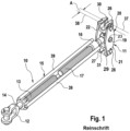
- the drawing shows a tensioning screw 10 with a rocker 11 attached to it.
- the tensioning screw 10 has a shackle 12 at its end opposite the rocker 11, by means of which it is attached in a known manner to a lashing eye on the deck of a ship.
- the end of the tensioning screw 10 with the shackle 12 is referred to as the lower end and the end with the rocker as the upper end.
- the shackle 12 is attached to a threaded spindle 13, which cooperates with a nut 14 of a tension screw body 15.
- the clamping screw body 15 has a further nut 16 at its (upper) end opposite the nut 13 on, which interacts with another threaded spindle 17.
- the threaded spindle 13 and nut 14 on the one hand and the further nut 16 and further threaded spindle 17 on the other hand are designed in opposite directions to one another, for example the threaded spindle 13 and nut 14 as a right-hand thread and the further nut 16 and further threaded spindle 17 as a left-hand thread, like that of clamping screws is known per se.
- the threaded spindle has a head 18 which is provided with a transverse bore (not shown in detail) (transverse to the longitudinal axis of the clamping screw 10).
- a bolt 19 is guided through this transverse hole, on which the rocker 11 is articulated.
- the rocker 11 has a housing 20, which in the present case has two rocker plates 21 and 22.
- a rocker plate 21 or 22 is arranged on each side of the head 18.
- the rocker plates 21, 22 are each provided with a bore 23 through which the bolt 19 is guided and secured against axial displacement in a suitable and known manner. In this way, the rocker 11 is articulated on the head 18 of the threaded spindle 17 and thus on the clamping screw 10.
- a further hole, not shown in detail, is guided through the head 18 of the threaded spindle 17, which is guided transversely to the longitudinal axis of the clamping screw 10 and transversely to the transverse bore for the bolt 19.
- a spring 25 ( Fig. 3 ), whose function is described below.
- the rocker 11 also has two receptacles 26 and 27, one on each side of the head 18.
- the receptacles 26, 27 thus form a two-armed lever with the bolt 18.
- the receptacles 26, 27 are also mounted in an articulated manner between the rocker plates 21, 22.
- the receptacles 26, 27 are provided with bolt stubs 28, which engage in corresponding bearing bores 29 in the rocker plates 21, 22 and are axially secured there against slipping out in a suitable manner known per se.
- the receptacles 26, 27 are each provided with a pocket 30, 31 that is open to the outside (away from the bolt 19), which serves to accommodate a lashing rod, not shown in detail but known per se.
- the pockets 30, 31 At the top, away from the tension screw 10 directed area, the pockets 30, 31 have a smaller diameter 32, which is adapted to the diameter of the lashing rods. This smaller diameter 32 merges over a shoulder 33 into a larger diameter 34, which corresponds to the diameter of lashing rod knobs, which are arranged axially one behind the other at certain distances at the lower end of a lashing rod.
- an outer slot 35 through which the respective pocket 30, 31 is opened to the outside, is always adapted to the diameter of the lashing rod and is narrower than a lashing rod knob. In this way, the lashing rod accidentally slipping out of the pocket 30, 31 is counteracted.
- the receptacles 26, 27 have eyelets 44 opposite the slots 35, which the spring 25 already mentioned above engages.
- the spring 25 is tensioned and in this way holds the receptacles 26, 27 in a desired position as long as no lashing rods have been inserted into the pockets 30, 31.
- the desired position is a position in which the longitudinal axis of the pockets 30, 31 runs approximately parallel to the longitudinal extent of the clamping screw 10, as shown in the drawing. This position is also referred to as a neutral position within the scope of the present disclosure.
- the bolt stubs 28 form a pivot axis 36 with the bearing bores 29, about which the receptacles 26, 27 can each rotate relative to the rocker plates 21, 22.
- the shoulders 33 of the pockets 30, 31 each describe a circular arc section which defines a plane which is in the Fig. 1 , 2 and 4 is indicated by line 37.
- the pivot axis 36 does not lie in this plane 37, but is arranged parallel to it. Specifically, it is offset by a suitable distance A, away from the clamping screw.
- the shoulders 33 are therefore arranged above the pivot axes 36 if the side facing the clamping screw 10 is defined as below, as already defined above.
- the distance A is the same for the shoulders 33 of both pockets 30, 31.
- the shoulders 33 of both pockets 30, 31 define a common plane 37, which is parallel to a plane 38 defined by the pivot axes 36 of both bolt stubs 28, which in the Fig. 2 and 4 is indicated by a line, extends with the distance A.
- This variant is preferred, not only because this means that two identically designed receptacles 26, 27 (mounted only rotated by 180 ° relative to one another) can be used, which simplifies production and reduces long-term maintenance.
- the distance A can be between 5 mm and 100 mm.
- the distance A can also be between 5 mm and 25 mm or between 25 and 100 mm. 25 mm has proven to be particularly cheap.
- the rocker 11 in the present exemplary embodiment is designed as a lever with the same arms, i.e. with the same distance between the bolt stubs 28 and the bolt 19.
- the rocker 11 it is also possible to have the rocker 11 with different distances between the bolt stubs 28 of one receptacle 26 and the other receptacle 27, i.e to be designed as an unequal-armed lever.
- the clamping screw 10 is designed with a clamping screw body 15, which has three rods 39 connecting the nuts 14 and 16.
- the rods 39 are arranged offset from one another by 120 ° on the circumference.
- In the lower nut 14 there are three balls 40, each arranged centrally between two rods 39, which are arranged in bores 41 on the inner circumference of the nut 14 and are biased towards the threaded spindle 13 by a spring 42.
- a longitudinal groove 43 is provided in the threaded spindle 13, into which the balls 40 can engage and thus secure the clamping screw against unwanted loosening (unintentional twisting of the threaded spindle 13 relative to the clamping screw body 15). In this way, three different positions for securing the clamping screw are possible with just one longitudinal groove 43.
Description
- Die Erfindung betrifft eine Vorrichtung gemäß Anspruch 1. Ferner betrifft die Erfindung eine Einheit aus einer Spannschraube und einer solchen Vorrichtung
- Eine Vorrichtung gemäß dem Oberbegriff von Anspruch 1sowie eine Einheit mit einer solchen Vorrichtung sind aus der
DE 20 2017 103 865 U1 bekannt. - Die in den
Fig. 4 bis 5 derDE 20 2017 103 865 Ulgezeigte Vorrichtung stellt eine Wippe dar, welche um einen Gelenkpunkt schwenkt. Der Gelenkpunkt ist konkret eine Bohrung, durch welche ein Bolzen gesteckt ist, der die Wippe mit einer Spannschraube verbindet. Die Bohrung definiert eine Schwenkachse, um welche die Wippe schwenken kann. Zu beiden Seiten der Bohrung befindet sich je eine Aufnahme, welcher ihrerseits mittels eines Gelenks schwenkbar am Gehäuse der Wippe angebracht sind. In die Aufnahmen kann jeweils eine Zurrstange eingehängt werden. Die jeweilige Zurrstange hakt mit einem ihrer Zurrstangenknäufe hinter eine Schulter der zugehörigen Aufnahme. - Die Schultern sind konkret umlaufend in einer nach außen offenen Tasche angeordnet. Durch die Öffnung werden die Zurrstangen in die Tasche eingesetzt. Die umlaufenden Schultern definieren jeweils eine Ebene, in welcher auch die durch das Gelenk der Aufnahmen gebildete Schwenkachse verläuft.
- Werden zwei übereinander gestapelte Container mit einer solchen Anordnung gezurrt, geht der Stauer wie folgt vor:
Die Wippe verbleibt in der Regel an der Spannschraube und wird außer für eventuelle Wartungs- oder Reparaturarbeiten nicht von der Spannschraube demontiert. Die Spannschraube wird mit ihrem der Wippe gegenüberliegenden Ende an einem Fundament befestigt, nämlich in der Regel mittels eines Schäkels an einem Zurrauge angeschlagen. Vorher oder anschließend hängt der Stauer eine Zurrstange in einen unteren Eckbeschlag des oberen Containers und eine weitere Zurrstange in den oberen Eckbeschlag des unteren Containers (oder umgekehrt) ein. Nun werden die Zurrstangen eine nach der anderen in die jeweilig zugehörige Aufnahme eingehakt. Dabei wählt der Stauer einen der Zurrstangenknäufe zum groben Einstellen der Länge aus und hakt diesen hinter die Schulter der Aufnahme. Ggf. hakt der Stauer auch eine Zurrstange in den zugehörigen Eckbeschlag und sodann in die zugehörige Aufnahme ein und fährt dann erst mit der zweite Zurrstange fort. Nun wird die so gebildete Anordnung mittels der Spannschraube gespannt. - Die Zurrstangen sind dabei je nach den geometrischen Verhältnissen nicht notwendiger Weise parallel zueinander angeordnet. Daher ist es zweckmäßig, die Aufnahmen ihrerseits, wie oben beschrieben, schwenkbar an dem Gehäuse der Wippe anzuordnen. Praxistests haben jedoch gezeigt, dass der Verlauf der Schwenkachse für die Aufnahmen in der durch die Schultern definierte Ebene das Einhaken der Zurrstangen in die Aufnahmen, insbesondere das Einhaken der zweiten Zurrstange bei bereits eingehängter erster Zurrstange, erschwert. Insbesondere ist es passiert, dass die bereits eingehängte erste Zurrstange wieder aus der Aufnahme viel, bevor oder während die zweite Zurrstange eingehängt wurde.
- Die zueinander inhaltsgleichen
DE 40 33 704 A1 undDE 90 14 696 U1 zeigen eine Spannschraube mit einer Wippe, welche zu beiden Seiten je eine feste Aufnahme für je einen Zurrstangenknauf aufweist. Durch ergeben sich die gleichen Nachteile wie oben anhand derDE 20 2017 103 865 U1 dargelegt. - Hiervon ausgehend liegt der Erfindung das Problem zugrunde, das Einhaken der Zurrstangen in die Aufnahmen zu erleichtern.
- Zur Lösung dieses Problems ist die erfindungsgemäße Vorrichtung dadurch gekennzeichnet, dass eine durch das jeweilige Gelenk gebildete Schwenkachse nicht in einer gedachten durch die Schulter definierten Ebene sondern parallel zu dieser Ebenen verläuft.
- Durch die erfindungsgemäße Anordnung entsteht ein gewisser Hebelarm zwischen der Schwenkachse und der Schulter. Sobald eine Zurrstange in die Aufnahme eingehängt ist, leitet die Zurrstange ein gewisses Drehmoment in die Aufnahme ein. Tests haben gezeigt, dass durch diese überraschend einfache Maßnahme die Aufnahme immer vorteilhaft positioniert und ein Herausfallen der Zurrstange aus der Aufnahme sicher verhindert wird. Dadurch wird das Einhaken der Zurrstange erleichtert.
- Erfindungsgemäß verlaufen durch die Schulter der einen Aufnahme definierte Ebene und die durch die Schulter der zweiten Aufnahme definierte Ebene parallel zueinander, wenn sich die Aufnahmen in einer neutralen Position befinden. In diesem Fall sind die Schultern also auf unterschiedlichem Niveau angeordnet, was beim Einlegen der Zurrstangen vorteilhaft sein kann. Erfindungsgemäß bilden die Schultern aber eine gemeinsame Ebene, sind also auf gleichem Niveau angeordnet. Auf diese Weise kann das Gehäuse der Vorrichtung symmetrisch und die Aufnahmen zueinander gleich ausgebildet werden. Dieses ist konstruktiv und fertigungstechnisch einfach und erleichtert die Lagerhaltung.
- Die Schwenkachse der einen Aufnahme und die Schwenkachse der anderen Aufnahme definieren nach einer weiteren Ausgestaltung der Erfindung eine Ebene, welche parallel zu der/den Ebene(n) verläuft. Auch dieses dient dem oben genannten Symmetriegedanken.
- Ein das Einhängen der Zurrstangen besonders erleichternder Abstand der Schultern zur Schwenkachse beträgt zwischen 5 mm und 100 mm, vorzugsweise 25 mm.
- An den Aufnahmen greift eine auf Zug vorgespannte Feder an, welche zwischen den Aufnahmen angeordnet ist. Auf diese Weise hält die Feder die Aufnahmen in einer gewünschten Position, solange noch keine Zurrstangen in die Taschen eingelegt sind.
- Die erfindungsgemäße Einheit ist zur Lösung des oben genannten Problems dadurch gekennzeichnet, dass die Schultern auf der der Spannschraube abgewandte Seite des jeweiligen Gelenks angeordnet sind. Mit anderen Worten sind die Schultern in der Einbausituation der Einheit oberhalb der Gelenke angeordnet. Hierdurch ergibt sich der das Einhängen der Zurrstangen erleichternde Hebel.
- Nach einer auch unabhängig denkbaren Weiterbildung der Einheit ist die Spannschraube mit einer Mutter versehen, welche drei oder mehr am Umfang verteilte und durch jeweils eine Feder nach innen vorgespannte Kugeln aufweist, welche mit wenigstens einer Längsnut an einer Gewindespindel zusammenwirken. Hierdurch ergeben sich je nach Zahl und Anordnung der Längsnuten wenigstens drei unterschiedliche Rastpositionen zum Sichern der Spannschraube gegen ungewolltes Lösen.
- Die Erfindung wird nachfolgend anhand eines in der Zeichnung dargestellten Ausführungsbeispiels näher erläutert. In der Zeichnung zeigen:
-
Fig. 1 eine Spannschraube mit der Vorrichtung mit den Erfindungsmerkmalen in perspektivischer Ansicht, -
Fig. 2 die Spannraube mit der Vorrichtung gemäßFig. 1 in Draufsicht, -
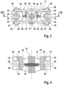
Fig. 3 die Spannschraube mit der Vorrichtung gemäßFig. 1 in einem Schnitt in der Ebene III-III gemäßFig. 2 , -
Fig. 4 die Vorrichtung gemäßFig. 1 im Längsschnitt in der Ebene IV-IV gemäßFig. 3 , -
Fig. 5 die Spannschraube gemäßFig. 1 in einem Schnitt in der Ebene V-V gemäßFig. 2 . - Die Zeichnung zeigt eine Spannschraube 10 mit einer daran angebrachten Wippe 11. Die Spannschraube 10 weist an ihrem der Wippe 11 gegenüberliegenden Ende eine Schäkel 12 auf, mittels welchem sie in bekannter Weise an einem Zurrauge an Deck eines Schiffes angeschlagen wird. Entsprechend der üblichen Einbausituation an Bord des Schiffes wird im Rahmen der vorliegenden Offenbarung das Ende der Spannschraube 10 mit dem Schäkel 12 als unteres Ende und das Ende mit der Wippe als oberes Ende bezeichnet.
- Der Schäkel 12 ist an einer Gewindespindel 13 angebracht, welche mit einer Mutter 14 eines Spannschraubenkörpers 15 zusammenwirkt. Der Spannschraubenkörper 15 weist an seinem der Mutter 13 gegenüberliegenden (oberen) Ende eine weitere Mutter 16 auf, welche mit einer weiteren Gewindespindel 17 zusammenwirkt. Die Gewindespindel 13 und Mutter 14 einerseits sowie die weitere Mutter 16 und weitere Gewindespindel 17 andererseits sind zueinander gegenläufig ausgebildet, also z.B. die Gewindespindel 13 und Mutter 14 als rechtsgängiges Gewinde sowie die weitere Mutter 16 und weitere Gewindespindel 17 als linksgängiges Gewinde, wie dieses von Spannschrauben an sich bekannt ist.
- An ihrem freien, aus dem Spannschraubenkörper 15 herausragenden Ende weist die Gewindespindel einen Kopf 18 auf, der mit einer nicht näher gezeigten Querbohrung (quer zur Längsachse der Spannschraube 10) versehen ist. Durch diese Querbohrung ist ein Bolzen 19 geführt, an welchem die Wippe 11 gelenkig gelagert ist. Die Wippe 11 weist ein Gehäuse 20 auf, welches im vorliegenden Fall zwei Wippenplatten 21 und 22 aufweist. Es ist jeweils eine Wippenplatte 21 bzw. 22 zu jeder Seite des Kopfes 18 angeordnet. Die Wippenplatten 21, 22 sind jeweils mit einer Bohrung 23 versehen, durch welche der Bolzen 19 geführt und gegen axiales Verschieben in geeigneter und an sich bekannter Weise gesichert ist. Auf diese Weise ist die Wippe 11 gelenkig am Kopf 18 der Gewindespindel 17 und damit an der Spannschraube 10 gelagert.
- Durch den Kopf 18 der Gewindespindel 17 ist eine weitere nicht näher gezeigte Bohrung geführt, welche quer zur Längsachse der Spannschraube 10 und quer zur Querbohrung für den Bolzen 19 geführt ist. Durch diese Bohrung ist eine Feder 25 (
Fig. 3 ) hindurchgeführt, deren Funktion weiter unten noch beschrieben wird. - Die Wippe 11 weist weiterhin zwei Aufnahmen 26 und 27 auf, und zwar jeweils eine zu beiden Seiten des Kopfes 18. Die Aufnahmen 26, 27 bilden somit mit dem Bolzen 18 einen zweiarmigen Hebel. Die Aufnahmen 26, 27 sind ebenfalls gelenkig zwischen den Wippenplatten 21, 22 gelagert. Die Aufnahmen 26, 27 sind zu diesem Zweck mit Bolzenstummeln 28 versehen, welche in korrespondierende Lagerbohrungen 29 in den Wippenplatten 21, 22 eingreifen und dort in geeigneter, an sich bekannter Weise gegen herausrutschen axial gesichert sind.
- Die Aufnahmen 26, 27 sind jeweils mit einer nach außen (vom Bolzen 19 weg) offenen Tasche 30, 31 versehen, welche zur Aufnahme einer nicht näher gezeigten aber an sich bekannten Zurrstange dient. An ihrem oberen, von der Spannschraube 10 weg gerichteten Bereich weisen die Taschen 30, 31 einen kleineren Durchmesser 32 auf, welcher dem Durchmesser der Zurrstangen angepasst ist. Dieser kleinere Durchmesser 32 geht über eine Schulter 33 in einen größeren Durchmesser 34 über, welcher dem Durchmesser von Zurrstangenknäufen entspricht, welche am unteren Ende einer Zurrstange in gewissen Abständen axial hintereinander angeordnet sind. Ein äußerer Schlitz 35, durch welchen die jeweilige Tasche 30, 31 nach außen geöffnet ist, ist jedoch immer dem Durchmesser der Zurrstange angepasst und schmaler als ein Zurrstangenknauf. Auf diese Weise wird einem versehentlichen seitlichen Herausrutschen der Zurrstange aus der Tasche 30, 31 entgegengewirkt.
- Die Aufnahmen 26, 27 weisen gegenüberliegend zu den Schlitzen 35 Ösen 44 auf, an welche die bereits oben erwähnte Feder 25 angreift. Die Feder 25 ist dabei auf Zug vorgespannt und hält auf diese Weise die Aufnahmen 26, 27 in einer gewünschten Position, solange noch keine Zurrstangen in die Taschen 30, 31 eingelegt sind. Die gewünschte Position ist dabei eine solche Position, bei welcher die Längsachse der Taschen 30, 31 in etwa parallel zur Längserstreckung der Spannschraube 10 verläuft, wie in der Zeichnung dargestellt. Diese Position wird im Rahmen der vorliegenden Offenbarung auch als neutrale Position bezeichnet.
- Die Bolzenstummel 28 bilden mit den Lagerbohrungen 29 eine Schwenkachse 36, um welche sich die Aufnahmen 26, 27 jeweils gegenüber den Wippenplatten 21, 22 verdrehen können. Ferner beschreiben die Schultern 33 der Taschen 30, 31 jeweils einen Kreisbogenabschnitt welcher eine Ebene definiert, welche in den
Fig. 1 ,2 und4 durch die Linie 37 angedeutet ist. Wie inFig. 1 ,2 und4 erkennbar, liegt die Schwenkachse 36 nicht in dieser Ebene 37, sondern ist parallel dazu angeordnet. Konkret ist sie um einen geeigneten Abstand A dazu versetzt, und zwar von der Spannschraube weg. Die Schultern 33 sind also oberhalb der Schwenkachsen 36 angeordnet, wenn die zur Spannschraube 10 weisende Seite wie bereits oben definiert als unten definiert wird. - Der Abstand A ist im gezeigten Ausführungsbeispiel für die Schultern 33 beider Taschen 30, 31 gleich. Mit anderen Worten definieren die Schultern 33 beider Taschen 30, 31 eine gemeinsame Ebenen 37, welche sich parallel zu einer durch die Schwenkachsen 36 beider Bolzenstummel 28 definierten Ebenen 38, welche in den
Fig. 2 und4 durch eine Linie angedeutet ist, mit eben dem Abstand A erstreckt. Diese Variante ist bevorzugt, nicht nur weil dadurch zwei identisch ausgebildete (nur um 180 ° verdreht zueinander montierte) Aufnahmen 26, 27 verwendet werden können, was die Fertigung vereinfacht und die Langerhaltung reduziert. Alternativ ist es aber auch vorstellbar, unterschiedliche Aufnahmen 26, 27 mit unterschiedlichem Abstand der Schultern 33 zur Schwenkachse 36 vorzusehen. Der Abstand A kann zwischen 5 mm und 100 mm betragen. Der Abstand A kann aber auch zwischen 5 mm und 25 mm oder zwischen 25 und 100 mm betragen. Als besonders günstig haben sich 25 mm erwiesen. - Ferner ist die Wippe 11 im vorliegenden Ausführungsbeispiel als gleicharmiger Hebel ausgebildet, also mit gleichem Abstand der Bolzenstummel 28 zum Bolzen 19. Alternativ ist es auch möglich, die Wippe 11 mit unterschiedlichen Abständen der Bolzenstummel 28 der einen Aufnahme 26 und der anderen Aufnahme 27, also als ungleicharmigen Hebel auszubilden.
- Ein weiterer, auch unabhängig von der vorliegenden Erfindung denkbarer Aspekt ist in
Fig. 5 näher gezeigt: Die Spannschraube 10 ist mit einem Spannschraubenkörper 15 ausgebildet, welcher über drei die Muttern 14 und 16 verbindende Stangen 39 verfügt. Die Stangen 39 sind dabei um 120 ° zueinander versetzt am Umfang angeordnet. In der Unteren Mutter 14 sind drei, jeweils mittig zwischen zwei Stangen 39 angeordnet Kugeln 40 vorgesehen, welche in Bohrungen 41 am Innenumfang der Mutter 14 angeordnet und durch eine Feder 42 in Richtung auf die Gewindespindel 13 vorgespannt sind. In der Gewindespindel 13 ist eine Längsnut 43 vorgesehen, in welche die Kugeln 40 eingreifen können und so die Spannschraube gegen ungewolltes Lösen (ungewolltes Verdrehen der Gewindespindel 13 gegenüber dem Spannschraubenkörper 15) sichern. Auf diese Wiese sind drei unterschiedliche Positionen zum Sichern der Spannschraube mit nur einer Längsnut 43 möglich. - Natürlich können auch zwei Längsnuten 90 ° oder 180 ° vorgesehen sein, wodurch sich sechs verschiedene Positionen für die Sicherung ergeben Ferner können auch drei um 120 ° versetzte Längsnuten mit nur einer federbelasteten Kugel 40 zusammenwirken. Die gezeigte Variante ist jedoch bevorzugt.
- 10
- Spannschraube
- 11
- Wippe
- 12
- Schäkel
- 13
- Gewindespindel
- 14
- Mutter
- 15
- Spannschraubenkörper
- 16
- Mutter
- 17
- Gewindespindel
- 18
- Kopf
- 19
- Bolzen
- 20
- Gehäuse
- 21
- Wippenplatte
- 22
- Wippenplatte
- 23
- Bohrung
- 25
- Feder
- 26
- Aufnahme
- 27
- Aufnahme
- 28
- Bolzenstummel
- 29
- Lagerbohrunge
- 30
- Tasche
- 31
- Tasche
- 32
- Durchmesser
- 33
- Schulter
- 34
- Durchmesser
- 35
- Schlitz
- 36
- Schwenkachse
- 37
- Ebene
- 38
- Ebene
- 39
- Stange
- 40
- Kugel
- 41
- Bohrung
- 42
- Feder
- 43
- Längsnut
Claims (6)
- Vorrichtung (11) zum Verzurren von Containern an Bord von Schiffen mit einem Gehäuse (20) sowie einer ersten Aufnahme (26) für einen ersten Zurrstangenknauf einer ersten Zurrstange und einer zweiten Aufnahme (27) für einen zweiten Zurrstangenknauf einer zweiten Zurrstange, welche jeweils eine Schulter (33) für den Zurrstangenknauf aufweisen, wobei die erste Aufnahme (26) und die zweite Aufnahme (28) jeweils durch ein Gelenk (28, 29) schwenkbar an dem Gehäuse (20) gelagert sind, dadurch gekennzeichnet, dass eine durch das jeweilige Gelenk (28, 29) gebildete Schwenkachse (36) nicht in einer gedachten durch die Schulter (33) definierten Ebene (37) sondern parallel zu dieser Ebene (37) verläuft, und dass an den Aufnahmen (26, 27) eine auf Zug vorgespannte Feder (25) angreift, welche zwischen den Aufnahmen (26, 27) angeordnet ist.
- Vorrichtung (11) nach Anspruch 1, dadurch gekennzeichnet, dass die durch die Schulter (33) der einen Aufnahme (26) definierte Ebene (37) und die durch die Schulter (33) der zweiten Aufnahme (27) definiere Ebene (37) parallel zueinander verlaufen oder eine gemeinsame Ebene (37) bilden, wenn sich die Aufnahmen (26, 27) in einer neutralen Position befinden.
- Vorrichtung (11) nach Anspruch 1 oder 2, dadurch gekennzeichnet, dass die Schwenkachse (37) der einen Aufnahme (26) und die Schwenkachse (37) der anderen Aufnahme (27) eine Ebene (38) definieren, welche parallel zu der/den Ebene(n) (37) verläuft.
- Vorrichtung (11) nach einem der Ansprüche 1 bis 3, dadurch gekennzeichnet, dass ein Abstand (A) zwischen der Schwenkachse (36) und der durch die Schultern (33) definierten Ebene (37) zwischen 5 mm und 100 mm, vorzugsweise 25 mm beträgt.
- Einheit aus einer Spannschraube (10) und der Vorrichtung (11) nach einem der Ansprüche 1 bis 5, dadurch gekennzeichnet, dass die Schultern (33) auf der der Spannschraube (10) abgewandte Seite des jeweiligen Gelenks (28, 29) angeordnet sind.
- Einheit nach Anspruch 5, dadurch gekennzeichnet, dass die Spannschraube (10) mit einer Mutter (14) versehen ist, welche drei oder mehr am Umfang verteilte und durch jeweils eine Feder (42) nach innen vorgespannte Kugeln (40) aufweist, welche mit wenigstens einer Längsnut (43) an einer Gewindespindel (13) zusammenwirken.
Applications Claiming Priority (1)
| Application Number | Priority Date | Filing Date | Title |
|---|---|---|---|
| DE202018105479.1U DE202018105479U1 (de) | 2018-09-24 | 2018-09-24 | Vorrichtung zum Verzurren von Containern an Bord von Schiffen |
Publications (2)
| Publication Number | Publication Date |
|---|---|
| EP3626532A1 EP3626532A1 (de) | 2020-03-25 |
| EP3626532B1 true EP3626532B1 (de) | 2023-11-15 |
Family
ID=64457965
Family Applications (1)
| Application Number | Title | Priority Date | Filing Date |
|---|---|---|---|
| EP19183779.8A Active EP3626532B1 (de) | 2018-09-24 | 2019-07-02 | Vorrichtung zum verzurren von containern an bord von schiffen |
Country Status (5)
| Country | Link |
|---|---|
| EP (1) | EP3626532B1 (de) |
| CN (1) | CN110937073B (de) |
| DE (1) | DE202018105479U1 (de) |
| DK (1) | DK3626532T3 (de) |
| FI (1) | FI3626532T3 (de) |
Families Citing this family (2)
| Publication number | Priority date | Publication date | Assignee | Title |
|---|---|---|---|---|
| US11352137B2 (en) * | 2019-01-09 | 2022-06-07 | Embraer S.A. | Aircraft cargo platform assemblies and aircraft modular auxiliary fuselage fuel tank systems employing the same |
| CN111976900B (zh) * | 2020-08-25 | 2021-07-13 | 中国船级社 | 一种集装箱外绑扎型式的绑扎强度的优化调整方法 |
Citations (1)
| Publication number | Priority date | Publication date | Assignee | Title |
|---|---|---|---|---|
| DE202017103865U1 (de) * | 2017-04-21 | 2017-07-05 | Sec Ship's Equipment Centre Bremen Gmbh & Co. Kg | Beschlagplatte sowie eine Vorrichtung und eine Anordnung zum Verzurren von Containern an Bord von Schiffen |
Family Cites Families (10)
| Publication number | Priority date | Publication date | Assignee | Title |
|---|---|---|---|---|
| DE9014696U1 (de) * | 1990-10-24 | 1991-01-24 | Mec Marine Equipment + Consulting Behr & Horstmann Gmbh, 2102 Hamburg, De | |
| DE4033704A1 (de) * | 1990-10-24 | 1992-04-30 | Marine Equip & Consult | Vorrichtung zum sichern von gestapelten transportbehaeltern |
| DE102006060901A1 (de) * | 2006-12-20 | 2008-06-26 | Macgregor (Deu) Gmbh | Kuppelstück zum lösbaren Verbinden von Containern |
| FI123300B (fi) * | 2011-06-08 | 2013-02-15 | Cargotec Finland Oy | Kytkentäelin |
| DE202013101779U1 (de) * | 2013-04-24 | 2013-05-08 | Sec Ship's Equipment Centre Bremen Gmbh & Co. Kg | Verlängerungsmittel für ein Zurrorgan, insbesondere zum Verzurren von Containern an Bord von Schiffen, sowie Verlängerungssystem und Zurrsystem |
| FI124623B (fi) * | 2013-06-27 | 2014-11-14 | Macgregor Finland Oy | Rahtilaivan surraussilta |
| DE102013214176B4 (de) * | 2013-07-19 | 2015-09-17 | German Lashing Robert Böck GmbH | Zurrvorrichtung zum Sichern von Containern |
| DE102014104104A1 (de) * | 2014-03-25 | 2015-10-01 | Sec Ship's Equipment Centre Bremen Gmbh & Co. Kg | Vorrichtung zum Verzurren von Containern |
| DE102015101731A1 (de) * | 2015-02-06 | 2016-08-25 | German Lashing Robert Böck GmbH | Zurrvorrichtung, -system und -verfahren |
| TWI641770B (zh) * | 2017-10-13 | 2018-11-21 | 謝榮寬 | Tie plate and tie device |
-
2018
- 2018-09-24 DE DE202018105479.1U patent/DE202018105479U1/de active Active
-
2019
- 2019-07-02 EP EP19183779.8A patent/EP3626532B1/de active Active
- 2019-07-02 DK DK19183779.8T patent/DK3626532T3/da active
- 2019-07-02 FI FIEP19183779.8T patent/FI3626532T3/fi active
- 2019-08-08 CN CN201910729661.0A patent/CN110937073B/zh active Active
Patent Citations (1)
| Publication number | Priority date | Publication date | Assignee | Title |
|---|---|---|---|---|
| DE202017103865U1 (de) * | 2017-04-21 | 2017-07-05 | Sec Ship's Equipment Centre Bremen Gmbh & Co. Kg | Beschlagplatte sowie eine Vorrichtung und eine Anordnung zum Verzurren von Containern an Bord von Schiffen |
Also Published As
| Publication number | Publication date |
|---|---|
| CN110937073A (zh) | 2020-03-31 |
| DE202018105479U1 (de) | 2018-11-08 |
| FI3626532T3 (fi) | 2024-02-08 |
| CN110937073B (zh) | 2022-03-25 |
| DK3626532T3 (da) | 2024-02-05 |
| EP3626532A1 (de) | 2020-03-25 |
Similar Documents
| Publication | Publication Date | Title |
|---|---|---|
| DE19641950C2 (de) | Haltemittel | |
| DE102010028423B4 (de) | Pedikelschraube und Vorrichtung zur Stabilisierung der Wirbelsäule | |
| DE60011580T2 (de) | Befestigungsvorrichtung | |
| EP0445591A1 (de) | Einrichtung zum Verbinden einer Lenksäule eines Kraftfahrzeuges mit einem Wellenzapfen eines Lenkgetriebes | |
| EP3626532B1 (de) | Vorrichtung zum verzurren von containern an bord von schiffen | |
| EP3206820A1 (de) | Spannsystem | |
| DE60011003T2 (de) | Permanente Verankerungsvorrichtung | |
| DE19525316C2 (de) | Einrichtung zur Fixierung des schwingenden Systems einer Haushaltsmaschine | |
| EP0047961B1 (de) | Kugelkopfkupplung für Kraftfahrzeuge | |
| DE4409765A1 (de) | Rohrbefestigungsvorrichtung | |
| EP1488989A2 (de) | Drehstangenverschluss für Türen, Klappen oder dgl. von Nutzfahrzeugaufbauten | |
| WO2011048025A1 (de) | Spannschraube sowie vorrichtung zum verzurren von containern an bord von schiffen mit einer solchen spannschraube | |
| DE1632929C3 (de) | Vorrichtung zum Zerstäuben von Flüssigkeiten -insbesondere für die Landwirtschaft zur Behandlung von angebauten Pflanzen | |
| DE102007041403B4 (de) | Spannschraube mit Schwerkraftsicherung | |
| DE2643264B2 (de) | Haltevorrichtung für die Hobelkette an Kohlenhobeln | |
| DE2802293C3 (de) | Spannvorrichtung für Kettenstränge | |
| DE3525322A1 (de) | Vorrichtung zum verspannen mindestens eines containers | |
| DE102017115950B4 (de) | Haltevorrichtung | |
| DE102009019955B4 (de) | Verriegelungsvorrichtung zum Sichern von Containern, insbesondere auf Schiffen | |
| DE102004015596B3 (de) | Teleskopdeichsel | |
| DE2643889A1 (de) | Walzvorrichtung fuer nahtlose rohre | |
| DE1966537U (de) | Drehverschluss zur loesbaren verbindung eines containers mit seinem fahrgestell. | |
| DE90935C (de) | ||
| DE1506222A1 (de) | Deckelverschluss fuer Behaelter | |
| DE8522360U1 (de) | Containerverriegelung |
Legal Events
| Date | Code | Title | Description |
|---|---|---|---|
| PUAI | Public reference made under article 153(3) epc to a published international application that has entered the european phase |
Free format text: ORIGINAL CODE: 0009012 |
|
| STAA | Information on the status of an ep patent application or granted ep patent |
Free format text: STATUS: REQUEST FOR EXAMINATION WAS MADE |
|
| 17P | Request for examination filed |
Effective date: 20190702 |
|
| AK | Designated contracting states |
Kind code of ref document: A1 Designated state(s): AL AT BE BG CH CY CZ DE DK EE ES FI FR GB GR HR HU IE IS IT LI LT LU LV MC MK MT NL NO PL PT RO RS SE SI SK SM TR |
|
| AX | Request for extension of the european patent |
Extension state: BA ME |
|
| STAA | Information on the status of an ep patent application or granted ep patent |
Free format text: STATUS: EXAMINATION IS IN PROGRESS |
|
| STAA | Information on the status of an ep patent application or granted ep patent |
Free format text: STATUS: EXAMINATION IS IN PROGRESS |
|
| 17Q | First examination report despatched |
Effective date: 20201218 |
|
| GRAP | Despatch of communication of intention to grant a patent |
Free format text: ORIGINAL CODE: EPIDOSNIGR1 |
|
| STAA | Information on the status of an ep patent application or granted ep patent |
Free format text: STATUS: GRANT OF PATENT IS INTENDED |
|
| INTG | Intention to grant announced |
Effective date: 20221129 |
|
| GRAJ | Information related to disapproval of communication of intention to grant by the applicant or resumption of examination proceedings by the epo deleted |
Free format text: ORIGINAL CODE: EPIDOSDIGR1 |
|
| STAA | Information on the status of an ep patent application or granted ep patent |
Free format text: STATUS: EXAMINATION IS IN PROGRESS |
|
| GRAP | Despatch of communication of intention to grant a patent |
Free format text: ORIGINAL CODE: EPIDOSNIGR1 |
|
| STAA | Information on the status of an ep patent application or granted ep patent |
Free format text: STATUS: GRANT OF PATENT IS INTENDED |
|
| INTC | Intention to grant announced (deleted) | ||
| INTG | Intention to grant announced |
Effective date: 20230426 |
|
| P01 | Opt-out of the competence of the unified patent court (upc) registered |
Effective date: 20230510 |
|
| GRAJ | Information related to disapproval of communication of intention to grant by the applicant or resumption of examination proceedings by the epo deleted |
Free format text: ORIGINAL CODE: EPIDOSDIGR1 |
|
| STAA | Information on the status of an ep patent application or granted ep patent |
Free format text: STATUS: EXAMINATION IS IN PROGRESS |
|
| GRAP | Despatch of communication of intention to grant a patent |
Free format text: ORIGINAL CODE: EPIDOSNIGR1 |
|
| STAA | Information on the status of an ep patent application or granted ep patent |
Free format text: STATUS: GRANT OF PATENT IS INTENDED |
|
| INTC | Intention to grant announced (deleted) | ||
| INTG | Intention to grant announced |
Effective date: 20230905 |
|
| GRAS | Grant fee paid |
Free format text: ORIGINAL CODE: EPIDOSNIGR3 |
|
| GRAA | (expected) grant |
Free format text: ORIGINAL CODE: 0009210 |
|
| STAA | Information on the status of an ep patent application or granted ep patent |
Free format text: STATUS: THE PATENT HAS BEEN GRANTED |
|
| AK | Designated contracting states |
Kind code of ref document: B1 Designated state(s): AL AT BE BG CH CY CZ DE DK EE ES FI FR GB GR HR HU IE IS IT LI LT LU LV MC MK MT NL NO PL PT RO RS SE SI SK SM TR |
|
| REG | Reference to a national code |
Ref country code: CH Ref legal event code: EP Ref country code: GB Ref legal event code: FG4D Free format text: NOT ENGLISH |
|
| REG | Reference to a national code |
Ref country code: DE Ref legal event code: R096 Ref document number: 502019009906 Country of ref document: DE |
|
| REG | Reference to a national code |
Ref country code: IE Ref legal event code: FG4D Free format text: LANGUAGE OF EP DOCUMENT: GERMAN |
|
| REG | Reference to a national code |
Ref country code: DK Ref legal event code: T3 Effective date: 20240202 |
|
| REG | Reference to a national code |
Ref country code: LT Ref legal event code: MG9D |
|
| REG | Reference to a national code |
Ref country code: NL Ref legal event code: MP Effective date: 20231115 |
|
| PG25 | Lapsed in a contracting state [announced via postgrant information from national office to epo] |
Ref country code: GR Free format text: LAPSE BECAUSE OF FAILURE TO SUBMIT A TRANSLATION OF THE DESCRIPTION OR TO PAY THE FEE WITHIN THE PRESCRIBED TIME-LIMIT Effective date: 20240216 |
|
| PG25 | Lapsed in a contracting state [announced via postgrant information from national office to epo] |
Ref country code: IS Free format text: LAPSE BECAUSE OF FAILURE TO SUBMIT A TRANSLATION OF THE DESCRIPTION OR TO PAY THE FEE WITHIN THE PRESCRIBED TIME-LIMIT Effective date: 20240315 |
|
| PG25 | Lapsed in a contracting state [announced via postgrant information from national office to epo] |
Ref country code: LT Free format text: LAPSE BECAUSE OF FAILURE TO SUBMIT A TRANSLATION OF THE DESCRIPTION OR TO PAY THE FEE WITHIN THE PRESCRIBED TIME-LIMIT Effective date: 20231115 |
|
| PG25 | Lapsed in a contracting state [announced via postgrant information from national office to epo] |
Ref country code: NL Free format text: LAPSE BECAUSE OF FAILURE TO SUBMIT A TRANSLATION OF THE DESCRIPTION OR TO PAY THE FEE WITHIN THE PRESCRIBED TIME-LIMIT Effective date: 20231115 |