EP3618197A1 - Mehradriges kabel - Google Patents
Mehradriges kabel Download PDFInfo
- Publication number
- EP3618197A1 EP3618197A1 EP19191624.6A EP19191624A EP3618197A1 EP 3618197 A1 EP3618197 A1 EP 3618197A1 EP 19191624 A EP19191624 A EP 19191624A EP 3618197 A1 EP3618197 A1 EP 3618197A1
- Authority
- EP
- European Patent Office
- Prior art keywords
- sleeve
- cable
- region
- shield
- connector
- Prior art date
- Legal status (The legal status is an assumption and is not a legal conclusion. Google has not performed a legal analysis and makes no representation as to the accuracy of the status listed.)
- Granted
Links
Images


Classifications
-
- H—ELECTRICITY
- H01—ELECTRIC ELEMENTS
- H01R—ELECTRICALLY-CONDUCTIVE CONNECTIONS; STRUCTURAL ASSOCIATIONS OF A PLURALITY OF MUTUALLY-INSULATED ELECTRICAL CONNECTING ELEMENTS; COUPLING DEVICES; CURRENT COLLECTORS
- H01R13/00—Details of coupling devices of the kinds covered by groups H01R12/70 or H01R24/00 - H01R33/00
- H01R13/648—Protective earth or shield arrangements on coupling devices, e.g. anti-static shielding
- H01R13/658—High frequency shielding arrangements, e.g. against EMI [Electro-Magnetic Interference] or EMP [Electro-Magnetic Pulse]
- H01R13/6591—Specific features or arrangements of connection of shield to conductive members
- H01R13/6592—Specific features or arrangements of connection of shield to conductive members the conductive member being a shielded cable
- H01R13/6593—Specific features or arrangements of connection of shield to conductive members the conductive member being a shielded cable the shield being composed of different pieces
-
- H—ELECTRICITY
- H02—GENERATION; CONVERSION OR DISTRIBUTION OF ELECTRIC POWER
- H02G—INSTALLATION OF ELECTRIC CABLES OR LINES, OR OF COMBINED OPTICAL AND ELECTRIC CABLES OR LINES
- H02G15/00—Cable fittings
- H02G15/02—Cable terminations
-
- H—ELECTRICITY
- H01—ELECTRIC ELEMENTS
- H01B—CABLES; CONDUCTORS; INSULATORS; SELECTION OF MATERIALS FOR THEIR CONDUCTIVE, INSULATING OR DIELECTRIC PROPERTIES
- H01B7/00—Insulated conductors or cables characterised by their form
- H01B7/17—Protection against damage caused by external factors, e.g. sheaths or armouring
- H01B7/18—Protection against damage caused by wear, mechanical force or pressure; Sheaths; Armouring
- H01B7/1875—Multi-layer sheaths
-
- H—ELECTRICITY
- H01—ELECTRIC ELEMENTS
- H01R—ELECTRICALLY-CONDUCTIVE CONNECTIONS; STRUCTURAL ASSOCIATIONS OF A PLURALITY OF MUTUALLY-INSULATED ELECTRICAL CONNECTING ELEMENTS; COUPLING DEVICES; CURRENT COLLECTORS
- H01R13/00—Details of coupling devices of the kinds covered by groups H01R12/70 or H01R24/00 - H01R33/00
- H01R13/646—Details of coupling devices of the kinds covered by groups H01R12/70 or H01R24/00 - H01R33/00 specially adapted for high-frequency, e.g. structures providing an impedance match or phase match
- H01R13/6473—Impedance matching
-
- H—ELECTRICITY
- H01—ELECTRIC ELEMENTS
- H01R—ELECTRICALLY-CONDUCTIVE CONNECTIONS; STRUCTURAL ASSOCIATIONS OF A PLURALITY OF MUTUALLY-INSULATED ELECTRICAL CONNECTING ELEMENTS; COUPLING DEVICES; CURRENT COLLECTORS
- H01R9/00—Structural associations of a plurality of mutually-insulated electrical connecting elements, e.g. terminal strips or terminal blocks; Terminals or binding posts mounted upon a base or in a case; Bases therefor
- H01R9/03—Connectors arranged to contact a plurality of the conductors of a multiconductor cable, e.g. tapping connections
-
- H—ELECTRICITY
- H01—ELECTRIC ELEMENTS
- H01B—CABLES; CONDUCTORS; INSULATORS; SELECTION OF MATERIALS FOR THEIR CONDUCTIVE, INSULATING OR DIELECTRIC PROPERTIES
- H01B7/00—Insulated conductors or cables characterised by their form
- H01B7/0009—Details relating to the conductive cores
-
- H—ELECTRICITY
- H01—ELECTRIC ELEMENTS
- H01R—ELECTRICALLY-CONDUCTIVE CONNECTIONS; STRUCTURAL ASSOCIATIONS OF A PLURALITY OF MUTUALLY-INSULATED ELECTRICAL CONNECTING ELEMENTS; COUPLING DEVICES; CURRENT COLLECTORS
- H01R13/00—Details of coupling devices of the kinds covered by groups H01R12/70 or H01R24/00 - H01R33/00
- H01R13/646—Details of coupling devices of the kinds covered by groups H01R12/70 or H01R24/00 - H01R33/00 specially adapted for high-frequency, e.g. structures providing an impedance match or phase match
-
- H—ELECTRICITY
- H01—ELECTRIC ELEMENTS
- H01R—ELECTRICALLY-CONDUCTIVE CONNECTIONS; STRUCTURAL ASSOCIATIONS OF A PLURALITY OF MUTUALLY-INSULATED ELECTRICAL CONNECTING ELEMENTS; COUPLING DEVICES; CURRENT COLLECTORS
- H01R13/00—Details of coupling devices of the kinds covered by groups H01R12/70 or H01R24/00 - H01R33/00
- H01R13/648—Protective earth or shield arrangements on coupling devices, e.g. anti-static shielding
- H01R13/658—High frequency shielding arrangements, e.g. against EMI [Electro-Magnetic Interference] or EMP [Electro-Magnetic Pulse]
- H01R13/6581—Shield structure
-
- H—ELECTRICITY
- H01—ELECTRIC ELEMENTS
- H01R—ELECTRICALLY-CONDUCTIVE CONNECTIONS; STRUCTURAL ASSOCIATIONS OF A PLURALITY OF MUTUALLY-INSULATED ELECTRICAL CONNECTING ELEMENTS; COUPLING DEVICES; CURRENT COLLECTORS
- H01R4/00—Electrically-conductive connections between two or more conductive members in direct contact, i.e. touching one another; Means for effecting or maintaining such contact; Electrically-conductive connections having two or more spaced connecting locations for conductors and using contact members penetrating insulation
- H01R4/10—Electrically-conductive connections between two or more conductive members in direct contact, i.e. touching one another; Means for effecting or maintaining such contact; Electrically-conductive connections having two or more spaced connecting locations for conductors and using contact members penetrating insulation effected solely by twisting, wrapping, bending, crimping, or other permanent deformation
- H01R4/18—Electrically-conductive connections between two or more conductive members in direct contact, i.e. touching one another; Means for effecting or maintaining such contact; Electrically-conductive connections having two or more spaced connecting locations for conductors and using contact members penetrating insulation effected solely by twisting, wrapping, bending, crimping, or other permanent deformation by crimping
Definitions
- the present invention relates to a cable or a connector arrangement with a cable.
- the present invention has for its object to provide a cable with improved electrical properties.
- the shielding which surrounds the cores limits an elongated cross section.
- the invention proposes to adapt the sleeve in the area in which the sleeve is to be connected to the shield to the contour or the cross section of the shield family.
- the invention furthermore proposes to provide an essentially round cross section in a second region of the sleeve.
- “elongated” is understood to mean that an extension in a first direction is greater than an extension in a second direction, the second direction being perpendicular to the first direction.
- An essentially round cross section is understood to mean round cross sections which can have indentations in the axial direction.
- elongated cross-sections can be substantially oblong, i.e. short sides are formed by semicircles, the long sides connecting the short sides.
- the term elongated does not rule out that the long sides can have indentations.
- the first region is formed on a first end of the sleeve on the connector side and the second region is formed on a second end. Accordingly, the invention can be applied to a cable with wires which are arranged next to one another and form an elongated cross section. However, it goes without saying that the invention can also be applied to cables with wires which are arranged in a round cross section. Accordingly, it can alternatively be provided that the sleeve has a round cross section at one end on the connector side and is elongated at an opposite end.
- the sleeve is formed on the shield and one end of the shield on the connector side is folded over the sleeve, the folded shield extending in particular behind the sleeve. In this case, an improved adhesion of the folded shield on the sleeve is guaranteed.
- the shielding Due to the shape of the sleeve, the shielding, which is folded over the support sleeve, is guided in such a way that air chambers between the outer conductors and cable cores are reduced, thereby reducing electrical interference points.
- the first area of the sleeve is shaped in such a way that the shielding of the line is brought into a defined, in particular contour-following, position with respect to the individual wires of the cable and the outer conductor of the connector.
- the at least two wires are twisted together.
- the invention has a particularly advantageous effect on "twisted pair” cables, since it is the case with conventional elongated sleeves a low manufacturing tolerance during assembly of the sleeve on the shield. Problems often arise when a sleeve is slightly twisted relative to the cable during assembly. This problem can be alleviated due to the second area with the round, i.e. rotationally symmetrical cross-section.
- the first region has two opposite U-shaped tabs. Accordingly, the sleeve can be interrupted in the first area. This has a particularly advantageous effect on the manufacturability or the manufacturing costs of a sleeve. Alternatively, it can be provided that the sleeve with the different cross sections in the first or second region has an offset between the first and the second region.
- the U-shaped tabs in one processing step, e.g. by crimping, so that they touch or overlap.
- the sleeve has an indentation which follows the contour of the shield.
- the indentation is accordingly created on the top or bottom between two wires. This improves the electrical properties of the cable in the area of the sleeve.
- the invention is also applicable to a connector assembly with a connector and with a cable as described above.
- the cable is connected to the connector at an end on the connector side, in that an outer conductor of the connector arrangement is crimped onto the cable.
- a cable can also be connected to another cable or, for example, to a radio module.
- the sleeve, the outer conductor and in particular the shield are crimped to one another in the second region.
- the crimp in the first area can thus be advantageously designed with regard to the holding force of the shield on the sleeve, and a crimp in the second area can be designed particularly advantageously with regard to the outer conductor and sleeve.
- FIG. 1 shows a sleeve 18 for mounting on a cable 10 according to an embodiment of the invention.
- the sleeve 18 has a first region 20 with an elongated cross section.
- the elongated cross section is approximately oblong and is formed by two opposite U-shaped tabs 30, 31. Between the tabs 30, 31, the sleeve 18 is interrupted by interruptions 34, 35, ie opposite ends of the tabs 30, 31 do not touch in an uncrimped state.
- the sleeve 18 also has a second region 22 with an essentially round cross section. This essentially means that the cross section of the second region 22 is only approximately round and has an indentation 32 on its upper side. The indentation 32 is located at a point which is in the assembled state between two wires 12.
- the first region 20 with the elongated cross section is formed on a first, connector-side end 24 of the sleeve 18.
- the second region 22 of the sleeve 18 is formed on the opposite cable end 26 of the sleeve.
- the first area 20 of the sleeve 18 is connected to the second area 22 of the sleeve via two webs 36, 37.
- the web 36 connects the U-shaped tab 31 to the second region 22 of the sleeve.
- the web 37 connects the tab 30 to the second region 22 of the sleeve.
- the Figure 2 shows a sleeve 18 according to Figure 1 in a side view.
- FIG. 3 shows a sleeve 18 according to Figure 1 respectively.
- Figure 2 in a further side view, the sleeve 18 according to the side view Figure 3 opposite the side view Figure 2 is rotated by 90 °.
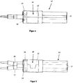
- the Figure 4 shows a cable 10 on which a sleeve 18 is mounted.
- the cable has two cores 12, which are each surrounded by an insulating means 16 and 17, respectively.
- the insulated wires 12 are surrounded by a common shield 14.
- the shield 14 forms an outer conductor of the cable, which shields the cores 12 from external electromagnetic influences.
- the shield 14 of the cable 10 originally extended between two opposite ends of the cable 10. However, the shield 14 was folded over the sleeve 18 in the course of further processing of the cable 10, such that the shield 14 extends from one end of the cable 10 to extends to the connector-side end 24 of the sleeve and is turned over at the connector-side end 24 of the sleeve around the sleeve 18. The folded shielding extends behind the sleeve 18.
- the Figure 5 shows a cable 10 according to Figure 4 in a side view, the side view according to Figure 5 opposite the side view of Figure 4 is rotated by 90 °.
- FIG. 6 shows a connector arrangement 50 with a cable 10 according to FIG Figure 4 respectively.
- Figure 5 in a side view.
- Figure 4 respectively.
- Figure 6 it can be seen that the shielding 14 or the outer conductor 52 does not optimally contact the cable in the first region 20 of the sleeve. Possible negative electrical effects due to this can, however, be weakened or compensated for by the sleeve 18 resting against the wires 12 in this area.
- the Figure 7 10 shows a connector assembly 50 according to FIG Figure 6 in a side view, the side view according to Figure 7 opposite the side view of Figure 6 is rotated by 90 °.
Landscapes
- Details Of Connecting Devices For Male And Female Coupling (AREA)
Abstract
Description
- Die vorliegende Erfindung betrifft ein Kabel bzw. eine Verbinderanordnung mit einem Kabel.
- Vor diesem Hintergrund liegt der vorliegenden Erfindung die Aufgabe zugrunde, ein Kabel mit verbesserten elektrischen Eigenschaften anzugeben.
- Erfindungsgemäß wird diese Aufgabe durch eine Baugruppe mit den Merkmalen des Patentanspruchs 1 gelöst.
- Demgemäß ist vorgesehen:
- ein Kabel, welches an einem Ende mit einem Verbinder verbindbar ist, mit wenigstens zwei Adern, einer Schirmung, einem Isoliermittel, welches zwischen den Adern und der Schirmung ausgebildet ist, und mit einer Hülse, welche an dem Ende des Kabels ausgebildet ist, wobei die Hülse einen ersten Bereich mit einem länglichen Querschnitt aufweist und einen zweiten Bereich mit einem im Wesentlichen runden Querschnitt aufweist.
- Aufgrund der wenigstens zwei Adern, die nebeneinander angeordnet sind, begrenzt die Schirmung, welche die Adern ummantelt, einen länglichen Querschnitt. Um die Haltekraft einer Hülse an der Schirmung zu erhöhen, schlägt die Erfindung vor, die Hülse in dem Bereich, in dem die Hülse mit der Schirmung zu verbinden ist, an die Kontur bzw. den Querschnitt des Schirmgeschlechts anzupassen.
- Da das Kabel mit der Hülse in der Regel im Rahmen einer weiteren Prozessierung mit einem Außenleiter von einem runden Querschnitt verbunden wird, schlägt die Erfindung ferner vor, in einem zweiten Bereich der Hülse einen im Wesentlichen runden Querschnitt vorzusehen.
- Unter "länglich" wird in dieser Anmeldung verstanden, dass eine Erstreckung in einer ersten Richtung größer ist als eine Erstreckung in einer zweiten Richtung, wobei die zweite Richtung zu der ersten Richtung senkrecht ist.
- Unter einem im Wesentlichen runden Querschnitt werden runde Querschnitte, die Einbuchtungen in axialer Richtung aufweisen können, verstanden.
- Längliche Querschnitte können beispielsweise im Wesentlichen langlochförmig sein, d.h. kurze Seiten werden durch Halbkreise gebildet, wobei die langen Seiten die kurzen Seiten verbinden. Der Begriff langlochförmig schließt nicht aus, dass die langen Seiten Einbuchtungen aufweisen können.
- Vorteilhafte Ausgestaltungen und Weiterbildungen ergeben sich aus den weiteren Unteransprüchen sowie aus der Beschreibung unter Bezugnahme auf die Figuren der Zeichnung.
- Es versteht sich, dass die voranstehend genannten und die nachstehend noch zu erläuternden Merkmale nicht nur in der jeweils angegebenen Kombination, sondern auch in anderen Kombinationen oder in Alleinstellung verwendbar sind, ohne den Rahmen der vorliegenden Erfindung zu verlassen.
- Gemäß einer bevorzugten Weiterbildung der Erfindung ist der erste Bereich an einem ersten verbinderseitigen Ende der Hülse und der zweite Bereich an einem zweiten Ende ausgebildet. Dementsprechend lässt sich die Erfindung auf ein Kabel mit Adern, die nebeneinander angeordnet sind und einen länglichen Querschnitt bilden, anwenden. Es versteht sich jedoch, dass die Erfindung auch auf Kabel mit Adern, die in einem runden Querschnitt angeordnet sind, anwendbar ist. Dementsprechend kann also alternativ vorgesehen sein, dass die Hülse an einem verbinderseitigen Ende einen runden Querschnitt aufweist und an einem gegenüberliegenden Ende länglich ausgebildet ist.
- Gemäß einer bevorzugten Weiterbildung der Erfindung ist die Hülse auf der Schirmung ausgebildet und ein verbinderseitiges Ende der Schirmung ist um die Hülse umgeschlagen, wobei sich die umgeschlagene Schirmung insbesondere bis hinter die Hülse erstreckt. In diesem Fall ist auch eine verbesserte Haftung der umgeschlagenen Schirmung auf der Hülse gewährleistet.
- Durch Hülsenform wird die Schirmung, welche um die Stützhülse umgeschlagen wird, derart geführt, dass Luftkammern zwischen Außenleitern und Kabeladern reduziert und dadurch elektrische Störstellen reduziert werden.
- Der erste Bereich der Hülse ist derart geformt, dass die Schirmung der Leitung in eine definierte, insbesondere konturfolgende, Lage zu den Einzeladern des Kabels und dem Außenleiter des Steckverbinders gebracht wird.
- Gemäß einer bevorzugten Weiterbildung der Erfindung sind die wenigstens zwei Adern miteinander verdrillt. In diesem Fall spricht man auch von sogenannten "twisted pair"-Kabeln. Die Erfindung wirkt sich auf "twisted pair"-Kabel besonders vorteilhaft aus, da es bei konventionellen länglichen Hülsen zu einer geringen Fertigungstoleranz während der Montage der Hülse auf der Schirmung kommt. Dabei kommt es oft zu Problemen, wenn eine Hülse gegenüber dem Kabel während der Montage geringgradig verdreht ist. Diese Problemstellung lässt sich aufgrund des zweiten Bereichs mit dem runden, also rotationssymmetrischen Querschnitt, entschärfen.
- Gemäß einer bevorzugten Weiterbildung der Erfindung weist der erste Bereich zwei gegenüberliegende U-förmige Laschen auf. Dementsprechend kann die Hülse in dem ersten Bereich unterbrochen sein. Dies wirkt sich besonders vorteilhaft auf die Herstellbarkeit bzw. die Herstellungskosten einer Hülse aus. Alternativ kann vorgesehen sein, dass die Hülse mit den verschiedenen Querschnitten in dem ersten bzw. zweiten Bereich eine Kröpfung zwischen dem ersten und dem zweiten Bereich aufweist.
- Dabei kann vorgesehen sein, dass die U-förmigen Laschen in einem Verarbeitungsschritt, z.B. durch Crimpen, derart verformt werden, dass diese sich berühren oder sich überlappen.
- Gemäß einer bevorzugten Weiterbildung der Erfindung weist die Hülse eine Einbuchtung, welche konturfolgend zu der Schirmung ist, auf. Die Einbuchtung entsteht dementsprechend auf der Ober- bzw. Unterseite zwischen zwei Adern. Hierdurch werden die elektrischen Eigenschaften des Kabels in dem Bereich der Hülse verbessert.
- Es versteht sich, dass die Erfindung sich auch auf eine Verbinderanordnung mit einem Verbinder und mit einem Kabel, wie es vorstehend beschrieben wurde, anwendbar ist. Dabei ist das Kabel an einem verbinderseitigen Ende mit dem Verbinder verbunden, indem ein Außenleiter der Verbinderanordnung mit dem Kabel vercrimpt ist.
- Es versteht sich jedoch, dass die vorliegende Erfindung auf sämtliche Verbindungsoptionen eines Kabels anwendbar ist. Dementsprechend lässt sich ein Kabel auch mit einem anderen Kabel oder beispielsweise mit einem Funkmodul verbinden.
- Gemäß einer bevorzugten Weiterbildung der Erfindung ist es dabei zweckmäßig, die Hülse, die Schirmung und den Außenleiter in dem ersten Bereich miteinander zu vercrimpen.
- Alternativ oder zusätzlich ist es dabei zweckmäßig, wenn die Hülse, der Außenleiter und insbesondere die Schirmung in dem zweiten Bereich miteinander vercrimpt sind.
- Es versteht sich, dass es insbesondere vorteilhaft ist, die Hülse, die Schirmung und den Außenleiter sowohl in dem ersten Bereich als auch in dem zweiten Bereich miteinander zu vercrimpen. Somit lässt sich der Crimp in dem ersten Bereich hinsichtlich der Haltekraft der Schirmung an der Hülse vorteilhaft auslegen und ein Crimp in dem zweiten Bereich lässt sich bezüglich des Außenleiters und Hülse besonders vorteilhaft ausgelegen.
- Die obigen Ausgestaltungen und Weiterbildungen lassen sich, sofern sinnvoll, beliebig miteinander kombinieren. Weitere mögliche Ausgestaltungen, Weiterbildungen und Implementierungen der Erfindung umfassen auch nicht explizit genannte Kombinationen von zuvor oder im Folgenden bezüglich der Ausführungsbeispiele beschriebenen Merkmale der Erfindung. Insbesondere wird dabei der Fachmann auch Einzelaspekte als Verbesserungen oder Ergänzungen zu der jeweiligen Grundform der vorliegenden Erfindung hinzufügen.
- Die vorliegende Erfindung wird nachfolgend anhand der in den schematischen Figuren der Zeichnung angegebenen Ausführungsbeispiele näher erläutert. Es zeigen dabei:
- Fig. 1
- eine schematische Perspektivansicht einer Hülse zur Montage an einem Kabel gemäß einer Ausführungsform der Erfindung;
- Fig. 2
- eine schematische Seitenansicht einer Hülse zur Montage an einem Kabel gemäß einer Ausführungsform der Erfindung;
- Fig. 3
- eine schematische Seitenansicht einer Hülse zur Montage an einem Kabel gemäß einer Ausführungsform der Erfindung;
- Fig. 4
- eine schematische Seitenansicht eines Kabels gemäß einer Ausführungsform der Erfindung;
- Fig. 5
- eine schematische Seitenansicht eines Kabels gemäß einer Ausführungsform der Erfindung;
- Fig. 6
- eine schematische Seitenansicht einer Verbinderanordnung gemäß einer Ausführungsform der Erfindung;
- Fig. 7
- eine schematische Seitenansicht einer Verbinderanordnung gemäß einer Ausführungsform der Erfindung.
- Die beiliegenden Figuren der Zeichnung sollen ein weiteres Verständnis der Ausführungsformen der Erfindung vermitteln. Sie veranschaulichen Ausführungsformen und dienen im Zusammenhang mit der Beschreibung der Erklärung von Prinzipien und Konzepten der Erfindung. Andere Ausführungsformen und viele der genannten Vorteile ergeben sich im Hinblick auf die Zeichnungen. Die Elemente der Zeichnungen sind nicht notwendigerweise maßstabsgetreu zueinander gezeigt.
- In den Figuren der Zeichnung sind gleiche, funktionsgleiche und gleich wirkende Elemente, Merkmale und Komponenten - sofern nichts anderes ausgeführt ist - jeweils mit denselben Bezugszeichen versehen.
- Im Folgenden werden die Figuren zusammenhängend und übergreifend beschrieben.
-
Figur 1 zeigt eine Hülse 18 zur Montage an einem Kabel 10 gemäß einer Ausführungsform der Erfindung. Die Hülse 18 weist einen ersten Bereich 20 mit einem länglichen Querschnitt auf. Der längliche Querschnitt ist in etwa langlochförmig und durch zwei gegenüberliegende U-förmige Laschen 30, 31 gebildet. Zwischen den Laschen 30, 31 ist die Hülse 18 von Unterbrechungen 34, 35 unterbrochen, d.h. gegenüberliegende Enden der Laschen 30, 31 berühren sich in einem unvercrimpten Zustand nicht. Die Hülse 18 weist ferner einen zweiten Bereich 22 mit einem im Wesentlichen runden Querschnitt auf. Im Wesentlichen bedeutet, dass der Querschnitt des zweiten Bereichs 22 lediglich näherungsweise rund ist und auf seiner Oberseite eine Einbuchtung 32 aufweist. Die Einbuchtung 32 befindet sich an einer Stelle, die sich in montiertem Zustand zwischen zwei Adern 12 befindet. - Dementsprechend ist in der
Figur 1 der erste Bereich 20 mit dem länglichen Querschnitt an einem ersten, verbinderseitigen Ende 24 der Hülse 18 ausgebildet. Der zweite Bereich 22 der Hülse 18 ist an dem gegenüberliegenden kabelseitigem Ende 26 der Hülse ausgebildet. - Der erste Bereich 20 der Hülse 18 ist mit dem zweiten Bereich 22 der Hülse über zwei Stege 36, 37 verbunden. Dabei verbindet der Steg 36 die U-förmige Lasche 31 mit dem zweiten Bereich 22 der Hülse. Der Steg 37 verbindet die Lasche 30 mit dem zweiten Bereich 22 der Hülse.
- Die
Figur 2 zeigt eine Hülse 18 gemäßFigur 1 in einer Seitenansicht. - Die
Figur 3 zeigt eine Hülse 18 gemäßFigur 1 bzw.Figur 2 in einer weiteren Seitenansicht, wobei die Hülse 18 in der Seitenansicht gemäßFigur 3 gegenüber der Seitenansicht ausFigur 2 um 90° gedreht ist. - Die
Figur 4 zeigt ein Kabel 10, auf welchem eine Hülse 18 montiert ist. Das Kabel weist zwei Adern 12 , welche jeweils von einem Isoliermittel 16 bzw. 17 umgeben sind, auf. Die isolierten Adern 12 sind von einer gemeinsamen Schirmung 14 umgeben. Die Schirmung 14 bildet einen Außenleiter des Kabels, der die Adern 12 vor äußeren elektromagnetischen Einflüssen abschirmt. - Die Schirmung 14 des Kabels 10 erstreckte sich ursprünglich zwischen zwei gegenüberliegenden Enden des Kabels 10. Die Schirmung 14 wurde jedoch im Rahmen einer weiteren Verarbeitung des Kabels 10 um die Hülse 18 umgeschlagen, derart, dass sich die Schirmung 14 von einem Ende des Kabels 10 bis zu dem verbinderseitigen Ende 24 der Hülse erstreckt und an dem verbinderseitigen Ende 24 der Hülse um die Hülse 18 umgeschlagen ist. Dabei erstreckt sich die umgeschlagene Schirmung bis hinter die Hülse 18.
- Die
Figur 5 zeigt ein Kabel 10 gemäßFigur 4 in einer Seitenansicht, wobei die Seitenansicht gemäßFigur 5 gegenüber der Seitenansicht vonFigur 4 um 90° verdreht ist. - Aus der Zusammenschau der
Figuren 4 und 5 geht hervor, dass die Schirmung 14 zwischen der Hülse 18 und den Adern 12 sich an den Querschnitt, den die beiden Adern 12 bilden, anlegt. Dementsprechend umschließt auch die Schirmung 14 einen länglichen Querschnitt. - Die
Figur 6 zeigt eine Verbinderanordnung 50 mit einem Kabel 10 gemäßFigur 4 bzw.Figur 5 in einer Seitenansicht. AusFigur 4 bzw.Figur 6 ist ersichtlich, dass sich die Schirmung 14 bzw. der Außenleiter 52 in dem ersten Bereich 20 der Hülse nicht optimal an das Kabel anlegen. Mögliche negative elektrische Auswirkungen aufgrund dessen können jedoch abgeschwächt oder kompensiert werden, indem die Hülse 18 in diesem Bereich an den Adern 12 anliegt. - Die
Figur 7 zeigt eine Verbinderanordnung 50 gemäßFigur 6 in einer Seitenansicht, wobei die Seitenansicht gemäßFigur 7 gegenüber der Seitenansicht vonFigur 6 um 90° verdreht ist. - Aus der Zusammenschau der
Figuren 4-7 ist ferner ersichtlich, dass der Außenleiter 52 bzw. die Schirmung 14 in dem zweiten Bereich 22 an der Hülse 18 anliegen. - Obwohl die vorliegende Erfindung anhand bevorzugter Ausführungsbeispiele vorstehend vollständig beschrieben wurde, ist sie darauf nicht beschränkt, sondern auf vielfältige Art und Weise modifizierbar.
-
- 10
- Kabel
- 12
- Adern
- 14
- Schirmung
- 16
- Isoliermittel
- 17
- Isoliermittel
- 18
- Hülse
- 20
- erster Bereich
- 22
- zweiter Bereich
- 24
- verbinderseitiges Ende der Hülse
- 26
- gegenüberliegendes Ende der Hülse
- 28
- Schirmung
- 30
- U-förmige Lasche
- 31
- U-förmige Lasche
- 32
- Einbuchtung
- 34
- Unterbrechung
- 35
- Unterbrechung
- 36
- Steg
- 37
- Steg
- 50
- Verbinderanordnung
- 52
- Außenleiter
Claims (12)
- Kabel (10), welches an einem Ende mit einem Verbinder verbindbar ist, mit
wenigstens zwei Adern (12),
einer Schirmung (14),
wenigstens einem Isoliermittel (16; 17), welches zwischen den Adern und der Schirmung ausgebildet ist, und mit einer Hülse (18), welche an dem Ende des Kabels ausgebildet ist,
wobei die Hülse einen ersten Bereich (20) mit einem länglichen Querschnitt aufweist und einen zweiten Bereich (22) mit einem im Wesentlichen runden Querschnitt aufweist. - Kabel nach Anspruch 1, wobei der erste Bereich an einem ersten verbinderseitigen Ende der Hülse (24) und der zweite Bereich an einem gegenüberliegenden Ende der Hülse (26) ausgebildet ist.
- Kabel nach einem der vorstehenden Ansprüche, wobei die Hülse auf der Schirmung ausgebildet ist, und ein verbinderseitiges Ende der Schirmung (28) um die Hülse umgeschlagen ist, wobei sich die umgeschlagene Schirmung (28) insbesondere bis hinter die Hülse erstreckt.
- Kabel nach einem der vorstehenden Ansprüche, wobei die wenigstens zwei Adern miteinander verdrillt sind.
- Kabel nach einem der vorstehenden Ansprüche, wobei der erste Bereich wenigstens zwei U-förmige Laschen (30, 31), insbesondere zwei gegenüberliegende oder vier Laschen, aufweist.
- Kabel nach Anspruch 5, wobei sich die U-förmigen Laschen kontaktieren oder überlappen.
- Kabel nach einem der vorstehenden Ansprüche, wobei die Hülse, insbesondere in dem zweiten Bereich, eine Einbuchtung (32), welche konturfolgend zu der Schirmung ist, aufweist.
- Kabel nach einem der vorstehenden Ansprüche, wobei die Hülse in dem ersten Bereich eine Unterbrechung, insbesondere zwei Unterbrechungen (34; 35), aufweist.
- Kabel nach einem der vorstehenden Ansprüche, wobei der erste Bereich der Hülse mit dem zweiten Bereich der Hülse mittels eines Stegs (36; 37) verbunden sind.
- Verbinderanordnung (50) mit einem Verbinder und mit einem Kabel nach einem der vorstehenden Ansprüche, welches an einem verbinderseitigen Ende mit dem Verbinder verbunden ist, indem ein Außenleiter (52) der Verbinderanordnung mit dem Kabel vercrimpt ist.
- Verbinderanordnung nach Anspruch 10, wobei die Hülse, die Schirmung und der Außenleiter in dem ersten Bereich miteinander vercrimpt sind.
- Verbinderanordnung nach einem der Ansprüche 10 oder 11, wobei die Hülse, der Außenleiter und insbesondere die Schirmung in dem zweiten Bereich miteinander vercrimpt sind.
Applications Claiming Priority (1)
| Application Number | Priority Date | Filing Date | Title |
|---|---|---|---|
| DE102018121239.9A DE102018121239A1 (de) | 2018-08-30 | 2018-08-30 | Mehradriges kabel |
Publications (2)
| Publication Number | Publication Date |
|---|---|
| EP3618197A1 true EP3618197A1 (de) | 2020-03-04 |
| EP3618197B1 EP3618197B1 (de) | 2021-07-07 |
Family
ID=67658750
Family Applications (1)
| Application Number | Title | Priority Date | Filing Date |
|---|---|---|---|
| EP19191624.6A Active EP3618197B1 (de) | 2018-08-30 | 2019-08-14 | Mehradrige kabelanordnung |
Country Status (4)
| Country | Link |
|---|---|
| US (1) | US10886720B2 (de) |
| EP (1) | EP3618197B1 (de) |
| CN (1) | CN110875556A (de) |
| DE (1) | DE102018121239A1 (de) |
Cited By (1)
| Publication number | Priority date | Publication date | Assignee | Title |
|---|---|---|---|---|
| US12580343B2 (en) | 2021-09-01 | 2026-03-17 | Fci Usa Llc | High speed, ruggedized connector |
Families Citing this family (3)
| Publication number | Priority date | Publication date | Assignee | Title |
|---|---|---|---|---|
| DE102021109486A1 (de) * | 2021-04-15 | 2022-10-20 | Te Connectivity Germany Gmbh | Elektrische Crimpferrule, Verfahren zur Ferrulenmontage sowie Verfahren zum Assemblieren einer elektrischen Verbindungseinrichtung |
| DE102021117039A1 (de) | 2021-07-01 | 2023-01-05 | Te Connectivity Germany Gmbh | Elektrische Mehradernkabel-Crimpferrule sowie Crimpverfahren |
| US12463382B2 (en) | 2021-11-24 | 2025-11-04 | Foxconn (Kunshan) Computer Connector Co., Ltd. | Electrical connector assembly having unitary ground bar wrapping around cable wires and method of making same |
Citations (2)
| Publication number | Priority date | Publication date | Assignee | Title |
|---|---|---|---|---|
| DE102006044479A1 (de) * | 2005-10-27 | 2007-05-03 | Yazaki Corp. | Verbinder |
| US20180026401A1 (en) * | 2016-07-21 | 2018-01-25 | Japan Aviation Electronics Industry, Limited | Connector and wire harness |
Family Cites Families (69)
| Publication number | Priority date | Publication date | Assignee | Title |
|---|---|---|---|---|
| US595650A (en) * | 1897-12-14 | Territory | ||
| US1426210A (en) * | 1920-09-23 | 1922-08-15 | Neil S Recorder Syndicate Ltd | Junction box for electric conductors |
| US1672201A (en) * | 1921-05-18 | 1928-06-05 | Ac Spark Plug Co | Terminal connecter for electrical supply cables |
| US2010530A (en) * | 1930-05-08 | 1935-08-06 | Gen Cable Corp | Electrical installation |
| US2106724A (en) * | 1935-03-16 | 1938-02-01 | Burton H Cope | Connecter |
| US2142818A (en) * | 1935-10-28 | 1939-01-03 | Illinois Tool Works | Electrical connecter |
| US2456554A (en) * | 1945-10-12 | 1948-12-14 | United Carr Fastener Corp | Connector for cords or cables |
| US3168614A (en) * | 1962-01-16 | 1965-02-02 | Simplex Wire & Cable Co | Armored cable connection |
| US3221294A (en) * | 1963-05-03 | 1965-11-30 | Amp Inc | Crimped electrical connections |
| US3262662A (en) * | 1963-12-09 | 1966-07-26 | Raymond A | Cable fastener |
| US3383457A (en) * | 1966-04-05 | 1968-05-14 | Amp Inc | Connector means for connecting coaxial cable to a printed circuit board |
| US3453376A (en) * | 1966-07-05 | 1969-07-01 | Amp Inc | Center contact structure for coaxial cable conductors |
| US3470524A (en) * | 1967-06-19 | 1969-09-30 | Deutsch Co Elec Comp | Push-pull connector |
| US3670293A (en) * | 1970-08-20 | 1972-06-13 | Amp Inc | Shielded wire connectors |
| BE794947A (fr) * | 1972-02-02 | 1973-08-02 | Raychem Corp | Procede et dispositif de connexion |
| US3793616A (en) * | 1972-02-23 | 1974-02-19 | Belden Corp | Terminal connector |
| US4010538A (en) * | 1975-07-01 | 1977-03-08 | Amp Incorporated | Phono plug |
| US4087889A (en) * | 1975-07-18 | 1978-05-09 | Kabushiki Kaisha Saneisha Seisakusho | Wire connecting sleeve |
| US4180101A (en) * | 1975-12-12 | 1979-12-25 | Wegurit Gesellschaft mbH Pipelinebedarf & Co. | Device for closing-off the space defined between an inner pipe and an outer shield tube |
| US4128735A (en) * | 1977-01-17 | 1978-12-05 | Trw Inc. | Attachment of electric cable to submergible pump motor heads |
| FR2507827B1 (fr) * | 1981-06-11 | 1985-10-04 | Electricfil Ind Sarl | Embout coude de raccordement electrique |
| US4619332A (en) * | 1984-03-29 | 1986-10-28 | Sheehan Robert K | Connector for a helically grooved metallic conduit |
| JPS61201283U (de) * | 1985-06-07 | 1986-12-17 | ||
| SE8901230D0 (sv) * | 1988-08-01 | 1989-04-07 | Aweidmueller Gmbh & Co C | Foerfarande foer framstaellning av med ett isoleringselement foersedda kontaktorgan saasom kontakthylsor och kabelskor och deras anbringande paa avisolerade ledaraendar, samt enligt foerfarandet framstaellda kontaktorgan |
| JP2723432B2 (ja) * | 1992-11-12 | 1998-03-09 | 矢崎総業株式会社 | 雌型端子金具 |
| JPH078970U (ja) * | 1993-07-06 | 1995-02-07 | 住友電装株式会社 | ゴム栓付き端子圧着電線 |
| US5437567A (en) * | 1993-08-09 | 1995-08-01 | Molex Incorporated | Female electrical terminal |
| JPH0736364U (ja) * | 1993-12-10 | 1995-07-04 | 住友電装株式会社 | 高圧抵抗電線用の端子 |
| JPH0817502A (ja) * | 1994-06-30 | 1996-01-19 | Yazaki Corp | 雌端子の接触部構造 |
| GB9417572D0 (en) * | 1994-09-01 | 1994-10-19 | Amp Gmbh | Electrical contact having improved locking lances |
| DE69602669T2 (de) * | 1995-03-27 | 1999-11-11 | The Whitaker Corp., Wilmington | Elektrischer Verbinder |
| US5594202A (en) * | 1995-04-06 | 1997-01-14 | Tobias; Michael A. | Split sleeve system |
| BR9709910A (pt) * | 1996-06-17 | 1999-08-10 | Framatome Connectors Int | Luva de ligacão de encaixe |
| JP2003297493A (ja) * | 2002-04-05 | 2003-10-17 | Auto Network Gijutsu Kenkyusho:Kk | 同軸コネクタ |
| US7355130B2 (en) * | 2004-04-09 | 2008-04-08 | Siemens Information And Communication Networks, Inc. | Cable sealing device |
| JP4381895B2 (ja) * | 2004-06-09 | 2009-12-09 | 株式会社オートネットワーク技術研究所 | コネクタとコネクタ付ケーブル及びその製造方法 |
| JP2006004820A (ja) * | 2004-06-18 | 2006-01-05 | Yazaki Corp | 同軸ケーブル用シールド端子 |
| US7273984B2 (en) * | 2005-07-11 | 2007-09-25 | Twins Investments Company | Outdoor cord connection cover apparatus |
| WO2007013589A1 (ja) * | 2005-07-29 | 2007-02-01 | Yazaki Corporation | アース用電線の止水方法およびアース用電線 |
| US7433571B2 (en) * | 2005-09-08 | 2008-10-07 | David Kendricks | Cable bundling and organizing system |
| US7252564B1 (en) * | 2006-01-27 | 2007-08-07 | Delphi Technologies, Inc. | Female electrical connector having crimping portions of double thickness |
| JP5033660B2 (ja) * | 2008-01-30 | 2012-09-26 | 矢崎総業株式会社 | 同軸コネクタ及び同軸コネクタの組み付け方法 |
| USD595653S1 (en) * | 2008-08-29 | 2009-07-07 | Centipede Systems, Inc. | Double ended resilient microelectronic connector |
| USD595650S1 (en) * | 2008-08-29 | 2009-07-07 | Centipede Systems, Inc. | Microelectronic connector |
| USD595652S1 (en) * | 2008-08-29 | 2009-07-07 | Centipede Systems, Inc. | Double ended microelectronic connector |
| USD595651S1 (en) * | 2008-08-29 | 2009-07-07 | Centipede Systems, Inc. | Resilient microelectronic connector |
| US8397452B2 (en) * | 2009-10-15 | 2013-03-19 | Specified Technologies Inc. | Firestopping bushing |
| US8272894B2 (en) * | 2010-11-05 | 2012-09-25 | Primecon Technology Ltd. | Coaxial connector |
| JP5711571B2 (ja) * | 2011-03-02 | 2015-05-07 | 矢崎総業株式会社 | 同軸ケーブルの端末処理構造および端末処理方法 |
| US8952274B2 (en) * | 2012-07-10 | 2015-02-10 | Thomas & Betts International, Inc. | Sleeve for protecting wire or cable |
| JP6060015B2 (ja) * | 2013-03-19 | 2017-01-11 | 矢崎総業株式会社 | 圧着端子の電線に対する圧着構造 |
| JP6075556B2 (ja) * | 2013-07-10 | 2017-02-08 | 株式会社オートネットワーク技術研究所 | 端子付き電線 |
| US9046194B2 (en) * | 2013-08-13 | 2015-06-02 | Specifiedtechnologies Inc. | Protective conduit for a structural panel opening |
| JP2015076236A (ja) * | 2013-10-08 | 2015-04-20 | 矢崎総業株式会社 | 圧着端子 |
| JP5991300B2 (ja) * | 2013-10-24 | 2016-09-14 | 住友電装株式会社 | スリット付き熱収縮チューブ |
| JP6360684B2 (ja) * | 2014-02-27 | 2018-07-18 | 矢崎総業株式会社 | 同軸コネクタ |
| JP6357334B2 (ja) * | 2014-03-28 | 2018-07-11 | 矢崎総業株式会社 | 圧着端子と電線の接続構造 |
| EP2980937B1 (de) * | 2014-07-30 | 2016-10-12 | MD Elektronik GmbH | Verfahren und Vorrichtung zum Herstellen eines geschirmten Kabels sowie ein geschirmtes Kabel |
| JP2016072067A (ja) * | 2014-09-30 | 2016-05-09 | ホシデン株式会社 | コネクタ |
| CA2963462C (en) * | 2014-10-03 | 2021-06-15 | General Cable Technologies Corporation | Wire and methods for preparing a wire to receive a contact element |
| DE202015000750U1 (de) * | 2015-01-30 | 2015-02-25 | Rosenberger Hochfrequenztechnik Gmbh & Co. Kg | Steckverbinderanordnung mit Kompensationshülse |
| JP2016197542A (ja) * | 2015-04-03 | 2016-11-24 | 住友電装株式会社 | コネクタ |
| JP6551187B2 (ja) * | 2015-11-24 | 2019-07-31 | 株式会社オートネットワーク技術研究所 | シールドコネクタ、及びコネクタ付きシールドケーブル |
| HUE045125T2 (hu) * | 2016-05-04 | 2019-12-30 | Md Elektronik Gmbh | Kábel |
| JP2018067496A (ja) * | 2016-10-21 | 2018-04-26 | 住友電装株式会社 | シールド端子及び外導体端子 |
| US10128607B2 (en) * | 2017-02-23 | 2018-11-13 | Te Connectivity Corporation | Sealed connector system |
| DE102017105682A1 (de) * | 2017-03-16 | 2018-09-20 | Te Connectivity Germany Gmbh | Kontaktträger, elektrische Kontakteinrichtung sowie Verfahren zum Herstellen eines konfektionierten Kabels |
| DE102017122048A1 (de) * | 2017-09-22 | 2019-03-28 | Te Connectivity Germany Gmbh | Elektrische Kontaktvorrichtung, elektrische Verbindungseinrichtung, sowie Verfahren zum Konfektionieren eines elektrischen Kabels |
| FR3074616B1 (fr) * | 2017-12-06 | 2019-11-01 | Raydiall | Piece d'adaptation d'impedance electrique pour connecteur monte sur cable a fils electriques isoles |
-
2018
- 2018-08-30 DE DE102018121239.9A patent/DE102018121239A1/de not_active Withdrawn
-
2019
- 2019-08-14 EP EP19191624.6A patent/EP3618197B1/de active Active
- 2019-08-21 US US16/546,476 patent/US10886720B2/en active Active
- 2019-08-30 CN CN201910815568.1A patent/CN110875556A/zh active Pending
Patent Citations (2)
| Publication number | Priority date | Publication date | Assignee | Title |
|---|---|---|---|---|
| DE102006044479A1 (de) * | 2005-10-27 | 2007-05-03 | Yazaki Corp. | Verbinder |
| US20180026401A1 (en) * | 2016-07-21 | 2018-01-25 | Japan Aviation Electronics Industry, Limited | Connector and wire harness |
Cited By (1)
| Publication number | Priority date | Publication date | Assignee | Title |
|---|---|---|---|---|
| US12580343B2 (en) | 2021-09-01 | 2026-03-17 | Fci Usa Llc | High speed, ruggedized connector |
Also Published As
| Publication number | Publication date |
|---|---|
| CN110875556A (zh) | 2020-03-10 |
| US10886720B2 (en) | 2021-01-05 |
| EP3618197B1 (de) | 2021-07-07 |
| US20200076179A1 (en) | 2020-03-05 |
| DE102018121239A1 (de) | 2020-03-05 |
Similar Documents
| Publication | Publication Date | Title |
|---|---|---|
| DE102018104253B4 (de) | Steckverbinderanordnung | |
| EP3403296B1 (de) | Aussenleiteranordnung für einen koaxial-steckverbinder | |
| EP3618197B1 (de) | Mehradrige kabelanordnung | |
| EP3396791B1 (de) | Aussenleiteranordnung | |
| EP3319182B1 (de) | Steckverbinderanordnung | |
| EP3685471B1 (de) | Hochstromsteckverbinder mit isolierhülse | |
| EP3327868B1 (de) | Elektrischer steckverbinder für ein mehradriges elektrisches kabel | |
| EP3327875B1 (de) | Elektrischer steckverbinder für ein mehradriges elektrisches kabel | |
| EP3422480A1 (de) | Kontaktsystem zur kontaktierung eines schirmgeflechts und eines kontaktelements | |
| DE102017006767A1 (de) | Steckverbinderanordnung | |
| EP3387710A1 (de) | Aussenleiteranordnung für einen koaxial-steckverbinder | |
| WO2024032936A1 (de) | Verbindungsanordnung zum elektrischen verbinden eines busteilnehmers an ein differentielles bussystem | |
| EP3573187B1 (de) | Steckverbinderanordnung | |
| EP3327869A1 (de) | Elektrischer steckverbinder für ein mehradriges elektrisches kabel | |
| EP4092836A1 (de) | Vorkonfektioniertes kabel, kabelsteckverbinderanordnung und elektrische steckverbindung | |
| EP3444907A1 (de) | Steckverbinderanordnung | |
| EP3364507A1 (de) | Elektrischer steckverbinder für ein mehradriges elektrisches kabel | |
| EP3367514A1 (de) | Steckverbindung für hochfrequenzanwendungen, zum beispiel für ethernet anwendung | |
| DE102011077886A1 (de) | Leitung sowie Verfahren zur Leitungskonfektionierung | |
| DE102017009370A1 (de) | Steckverbinderanordnung | |
| EP3595099B1 (de) | Adernkreuzer | |
| EP3327876B1 (de) | Elektrischer steckverbinder für ein mehradriges elektrisches kabel | |
| DE102020108376A1 (de) | Steckverbinder mit PE-Kontakt | |
| DE102015104551A1 (de) | Mehrreihiger Kabelstecker | |
| WO2019214775A1 (de) | Elektrischer steckverbinder für ein mehradriges elektrisches kabel |
Legal Events
| Date | Code | Title | Description |
|---|---|---|---|
| PUAI | Public reference made under article 153(3) epc to a published international application that has entered the european phase |
Free format text: ORIGINAL CODE: 0009012 |
|
| STAA | Information on the status of an ep patent application or granted ep patent |
Free format text: STATUS: THE APPLICATION HAS BEEN PUBLISHED |
|
| AK | Designated contracting states |
Kind code of ref document: A1 Designated state(s): AL AT BE BG CH CY CZ DE DK EE ES FI FR GB GR HR HU IE IS IT LI LT LU LV MC MK MT NL NO PL PT RO RS SE SI SK SM TR |
|
| AX | Request for extension of the european patent |
Extension state: BA ME |
|
| STAA | Information on the status of an ep patent application or granted ep patent |
Free format text: STATUS: REQUEST FOR EXAMINATION WAS MADE |
|
| 17P | Request for examination filed |
Effective date: 20200901 |
|
| RBV | Designated contracting states (corrected) |
Designated state(s): AL AT BE BG CH CY CZ DE DK EE ES FI FR GB GR HR HU IE IS IT LI LT LU LV MC MK MT NL NO PL PT RO RS SE SI SK SM TR |
|
| GRAP | Despatch of communication of intention to grant a patent |
Free format text: ORIGINAL CODE: EPIDOSNIGR1 |
|
| STAA | Information on the status of an ep patent application or granted ep patent |
Free format text: STATUS: GRANT OF PATENT IS INTENDED |
|
| INTG | Intention to grant announced |
Effective date: 20210323 |
|
| GRAS | Grant fee paid |
Free format text: ORIGINAL CODE: EPIDOSNIGR3 |
|
| GRAA | (expected) grant |
Free format text: ORIGINAL CODE: 0009210 |
|
| STAA | Information on the status of an ep patent application or granted ep patent |
Free format text: STATUS: THE PATENT HAS BEEN GRANTED |
|
| AK | Designated contracting states |
Kind code of ref document: B1 Designated state(s): AL AT BE BG CH CY CZ DE DK EE ES FI FR GB GR HR HU IE IS IT LI LT LU LV MC MK MT NL NO PL PT RO RS SE SI SK SM TR |
|
| REG | Reference to a national code |
Ref country code: GB Ref legal event code: FG4D Free format text: NOT ENGLISH |
|
| REG | Reference to a national code |
Ref country code: AT Ref legal event code: REF Ref document number: 1409489 Country of ref document: AT Kind code of ref document: T Effective date: 20210715 |
|
| REG | Reference to a national code |
Ref country code: DE Ref legal event code: R096 Ref document number: 502019001771 Country of ref document: DE |
|
| REG | Reference to a national code |
Ref country code: IE Ref legal event code: FG4D Free format text: LANGUAGE OF EP DOCUMENT: GERMAN |
|
| REG | Reference to a national code |
Ref country code: SE Ref legal event code: TRGR |
|
| REG | Reference to a national code |
Ref country code: LT Ref legal event code: MG9D |
|
| REG | Reference to a national code |
Ref country code: NL Ref legal event code: MP Effective date: 20210707 |
|
| PG25 | Lapsed in a contracting state [announced via postgrant information from national office to epo] |
Ref country code: RS Free format text: LAPSE BECAUSE OF FAILURE TO SUBMIT A TRANSLATION OF THE DESCRIPTION OR TO PAY THE FEE WITHIN THE PRESCRIBED TIME-LIMIT Effective date: 20210707 Ref country code: FI Free format text: LAPSE BECAUSE OF FAILURE TO SUBMIT A TRANSLATION OF THE DESCRIPTION OR TO PAY THE FEE WITHIN THE PRESCRIBED TIME-LIMIT Effective date: 20210707 Ref country code: ES Free format text: LAPSE BECAUSE OF FAILURE TO SUBMIT A TRANSLATION OF THE DESCRIPTION OR TO PAY THE FEE WITHIN THE PRESCRIBED TIME-LIMIT Effective date: 20210707 Ref country code: LT Free format text: LAPSE BECAUSE OF FAILURE TO SUBMIT A TRANSLATION OF THE DESCRIPTION OR TO PAY THE FEE WITHIN THE PRESCRIBED TIME-LIMIT Effective date: 20210707 Ref country code: BG Free format text: LAPSE BECAUSE OF FAILURE TO SUBMIT A TRANSLATION OF THE DESCRIPTION OR TO PAY THE FEE WITHIN THE PRESCRIBED TIME-LIMIT Effective date: 20211007 Ref country code: HR Free format text: LAPSE BECAUSE OF FAILURE TO SUBMIT A TRANSLATION OF THE DESCRIPTION OR TO PAY THE FEE WITHIN THE PRESCRIBED TIME-LIMIT Effective date: 20210707 Ref country code: PT Free format text: LAPSE BECAUSE OF FAILURE TO SUBMIT A TRANSLATION OF THE DESCRIPTION OR TO PAY THE FEE WITHIN THE PRESCRIBED TIME-LIMIT Effective date: 20211108 Ref country code: NO Free format text: LAPSE BECAUSE OF FAILURE TO SUBMIT A TRANSLATION OF THE DESCRIPTION OR TO PAY THE FEE WITHIN THE PRESCRIBED TIME-LIMIT Effective date: 20211007 Ref country code: NL Free format text: LAPSE BECAUSE OF FAILURE TO SUBMIT A TRANSLATION OF THE DESCRIPTION OR TO PAY THE FEE WITHIN THE PRESCRIBED TIME-LIMIT Effective date: 20210707 |
|
| PG25 | Lapsed in a contracting state [announced via postgrant information from national office to epo] |
Ref country code: PL Free format text: LAPSE BECAUSE OF FAILURE TO SUBMIT A TRANSLATION OF THE DESCRIPTION OR TO PAY THE FEE WITHIN THE PRESCRIBED TIME-LIMIT Effective date: 20210707 Ref country code: LV Free format text: LAPSE BECAUSE OF FAILURE TO SUBMIT A TRANSLATION OF THE DESCRIPTION OR TO PAY THE FEE WITHIN THE PRESCRIBED TIME-LIMIT Effective date: 20210707 Ref country code: GR Free format text: LAPSE BECAUSE OF FAILURE TO SUBMIT A TRANSLATION OF THE DESCRIPTION OR TO PAY THE FEE WITHIN THE PRESCRIBED TIME-LIMIT Effective date: 20211008 |
|
| REG | Reference to a national code |
Ref country code: DE Ref legal event code: R097 Ref document number: 502019001771 Country of ref document: DE |
|
| REG | Reference to a national code |
Ref country code: BE Ref legal event code: MM Effective date: 20210831 |
|
| PG25 | Lapsed in a contracting state [announced via postgrant information from national office to epo] |
Ref country code: DK Free format text: LAPSE BECAUSE OF FAILURE TO SUBMIT A TRANSLATION OF THE DESCRIPTION OR TO PAY THE FEE WITHIN THE PRESCRIBED TIME-LIMIT Effective date: 20210707 |
|
| PLBE | No opposition filed within time limit |
Free format text: ORIGINAL CODE: 0009261 |
|
| STAA | Information on the status of an ep patent application or granted ep patent |
Free format text: STATUS: NO OPPOSITION FILED WITHIN TIME LIMIT |
|
| PG25 | Lapsed in a contracting state [announced via postgrant information from national office to epo] |
Ref country code: SM Free format text: LAPSE BECAUSE OF FAILURE TO SUBMIT A TRANSLATION OF THE DESCRIPTION OR TO PAY THE FEE WITHIN THE PRESCRIBED TIME-LIMIT Effective date: 20210707 Ref country code: SK Free format text: LAPSE BECAUSE OF FAILURE TO SUBMIT A TRANSLATION OF THE DESCRIPTION OR TO PAY THE FEE WITHIN THE PRESCRIBED TIME-LIMIT Effective date: 20210707 Ref country code: RO Free format text: LAPSE BECAUSE OF FAILURE TO SUBMIT A TRANSLATION OF THE DESCRIPTION OR TO PAY THE FEE WITHIN THE PRESCRIBED TIME-LIMIT Effective date: 20210707 Ref country code: MC Free format text: LAPSE BECAUSE OF FAILURE TO SUBMIT A TRANSLATION OF THE DESCRIPTION OR TO PAY THE FEE WITHIN THE PRESCRIBED TIME-LIMIT Effective date: 20210707 Ref country code: LU Free format text: LAPSE BECAUSE OF NON-PAYMENT OF DUE FEES Effective date: 20210814 Ref country code: EE Free format text: LAPSE BECAUSE OF FAILURE TO SUBMIT A TRANSLATION OF THE DESCRIPTION OR TO PAY THE FEE WITHIN THE PRESCRIBED TIME-LIMIT Effective date: 20210707 Ref country code: CZ Free format text: LAPSE BECAUSE OF FAILURE TO SUBMIT A TRANSLATION OF THE DESCRIPTION OR TO PAY THE FEE WITHIN THE PRESCRIBED TIME-LIMIT Effective date: 20210707 Ref country code: AL Free format text: LAPSE BECAUSE OF FAILURE TO SUBMIT A TRANSLATION OF THE DESCRIPTION OR TO PAY THE FEE WITHIN THE PRESCRIBED TIME-LIMIT Effective date: 20210707 |
|
| 26N | No opposition filed |
Effective date: 20220408 |
|
| PG25 | Lapsed in a contracting state [announced via postgrant information from national office to epo] |
Ref country code: IE Free format text: LAPSE BECAUSE OF NON-PAYMENT OF DUE FEES Effective date: 20210814 Ref country code: BE Free format text: LAPSE BECAUSE OF NON-PAYMENT OF DUE FEES Effective date: 20210831 |
|
| REG | Reference to a national code |
Ref country code: CH Ref legal event code: PL |
|
| PG25 | Lapsed in a contracting state [announced via postgrant information from national office to epo] |
Ref country code: LI Free format text: LAPSE BECAUSE OF NON-PAYMENT OF DUE FEES Effective date: 20220831 Ref country code: CH Free format text: LAPSE BECAUSE OF NON-PAYMENT OF DUE FEES Effective date: 20220831 |
|
| PG25 | Lapsed in a contracting state [announced via postgrant information from national office to epo] |
Ref country code: CY Free format text: LAPSE BECAUSE OF FAILURE TO SUBMIT A TRANSLATION OF THE DESCRIPTION OR TO PAY THE FEE WITHIN THE PRESCRIBED TIME-LIMIT Effective date: 20210707 |
|
| P01 | Opt-out of the competence of the unified patent court (upc) registered |
Effective date: 20230525 |
|
| PG25 | Lapsed in a contracting state [announced via postgrant information from national office to epo] |
Ref country code: HU Free format text: LAPSE BECAUSE OF FAILURE TO SUBMIT A TRANSLATION OF THE DESCRIPTION OR TO PAY THE FEE WITHIN THE PRESCRIBED TIME-LIMIT; INVALID AB INITIO Effective date: 20190814 |
|
| PG25 | Lapsed in a contracting state [announced via postgrant information from national office to epo] |
Ref country code: MK Free format text: LAPSE BECAUSE OF FAILURE TO SUBMIT A TRANSLATION OF THE DESCRIPTION OR TO PAY THE FEE WITHIN THE PRESCRIBED TIME-LIMIT Effective date: 20210707 |
|
| PG25 | Lapsed in a contracting state [announced via postgrant information from national office to epo] |
Ref country code: MT Free format text: LAPSE BECAUSE OF FAILURE TO SUBMIT A TRANSLATION OF THE DESCRIPTION OR TO PAY THE FEE WITHIN THE PRESCRIBED TIME-LIMIT Effective date: 20210707 |
|
| PGFP | Annual fee paid to national office [announced via postgrant information from national office to epo] |
Ref country code: DE Payment date: 20250827 Year of fee payment: 7 |
|
| PGFP | Annual fee paid to national office [announced via postgrant information from national office to epo] |
Ref country code: IT Payment date: 20250825 Year of fee payment: 7 |
|
| REG | Reference to a national code |
Ref country code: AT Ref legal event code: MM01 Ref document number: 1409489 Country of ref document: AT Kind code of ref document: T Effective date: 20240814 |
|
| PGFP | Annual fee paid to national office [announced via postgrant information from national office to epo] |
Ref country code: GB Payment date: 20250826 Year of fee payment: 7 |
|
| PG25 | Lapsed in a contracting state [announced via postgrant information from national office to epo] |
Ref country code: AT Free format text: LAPSE BECAUSE OF NON-PAYMENT OF DUE FEES Effective date: 20240814 |
|
| PGFP | Annual fee paid to national office [announced via postgrant information from national office to epo] |
Ref country code: FR Payment date: 20250825 Year of fee payment: 7 |
|
| PGFP | Annual fee paid to national office [announced via postgrant information from national office to epo] |
Ref country code: SE Payment date: 20250825 Year of fee payment: 7 |
|
| PG25 | Lapsed in a contracting state [announced via postgrant information from national office to epo] |
Ref country code: TR Free format text: LAPSE BECAUSE OF FAILURE TO SUBMIT A TRANSLATION OF THE DESCRIPTION OR TO PAY THE FEE WITHIN THE PRESCRIBED TIME-LIMIT Effective date: 20210707 |
|
| PGFP | Annual fee paid to national office [announced via postgrant information from national office to epo] |
Ref country code: AT Payment date: 20260410 Year of fee payment: 5 |