EP3616992A1 - Dispositif de réglage pour un phare de véhicule automobile - Google Patents
Dispositif de réglage pour un phare de véhicule automobile Download PDFInfo
- Publication number
- EP3616992A1 EP3616992A1 EP18191005.0A EP18191005A EP3616992A1 EP 3616992 A1 EP3616992 A1 EP 3616992A1 EP 18191005 A EP18191005 A EP 18191005A EP 3616992 A1 EP3616992 A1 EP 3616992A1
- Authority
- EP
- European Patent Office
- Prior art keywords
- adjusting
- motor vehicle
- guide part
- vehicle headlight
- displacement axis
- Prior art date
- Legal status (The legal status is an assumption and is not a legal conclusion. Google has not performed a legal analysis and makes no representation as to the accuracy of the status listed.)
- Granted
Links
- 238000006073 displacement reaction Methods 0.000 claims abstract description 27
- 230000005540 biological transmission Effects 0.000 claims abstract description 24
- 230000008878 coupling Effects 0.000 claims abstract description 22
- 238000010168 coupling process Methods 0.000 claims abstract description 22
- 238000005859 coupling reaction Methods 0.000 claims abstract description 22
- 230000013011 mating Effects 0.000 abstract description 2
- 230000003287 optical effect Effects 0.000 description 2
- 230000000712 assembly Effects 0.000 description 1
- 238000000429 assembly Methods 0.000 description 1
- 230000001747 exhibiting effect Effects 0.000 description 1
- 230000002349 favourable effect Effects 0.000 description 1
Images

Classifications
-
- F—MECHANICAL ENGINEERING; LIGHTING; HEATING; WEAPONS; BLASTING
- F21—LIGHTING
- F21S—NON-PORTABLE LIGHTING DEVICES; SYSTEMS THEREOF; VEHICLE LIGHTING DEVICES SPECIALLY ADAPTED FOR VEHICLE EXTERIORS
- F21S41/00—Illuminating devices specially adapted for vehicle exteriors, e.g. headlamps
- F21S41/60—Illuminating devices specially adapted for vehicle exteriors, e.g. headlamps characterised by a variable light distribution
-
- B—PERFORMING OPERATIONS; TRANSPORTING
- B60—VEHICLES IN GENERAL
- B60Q—ARRANGEMENT OF SIGNALLING OR LIGHTING DEVICES, THE MOUNTING OR SUPPORTING THEREOF OR CIRCUITS THEREFOR, FOR VEHICLES IN GENERAL
- B60Q1/00—Arrangement of optical signalling or lighting devices, the mounting or supporting thereof or circuits therefor
- B60Q1/02—Arrangement of optical signalling or lighting devices, the mounting or supporting thereof or circuits therefor the devices being primarily intended to illuminate the way ahead or to illuminate other areas of way or environments
- B60Q1/04—Arrangement of optical signalling or lighting devices, the mounting or supporting thereof or circuits therefor the devices being primarily intended to illuminate the way ahead or to illuminate other areas of way or environments the devices being headlights
- B60Q1/06—Arrangement of optical signalling or lighting devices, the mounting or supporting thereof or circuits therefor the devices being primarily intended to illuminate the way ahead or to illuminate other areas of way or environments the devices being headlights adjustable, e.g. remotely-controlled from inside vehicle
- B60Q1/068—Arrangement of optical signalling or lighting devices, the mounting or supporting thereof or circuits therefor the devices being primarily intended to illuminate the way ahead or to illuminate other areas of way or environments the devices being headlights adjustable, e.g. remotely-controlled from inside vehicle by mechanical means
- B60Q1/0683—Adjustable by rotation of a screw
-
- B—PERFORMING OPERATIONS; TRANSPORTING
- B60—VEHICLES IN GENERAL
- B60Q—ARRANGEMENT OF SIGNALLING OR LIGHTING DEVICES, THE MOUNTING OR SUPPORTING THEREOF OR CIRCUITS THEREFOR, FOR VEHICLES IN GENERAL
- B60Q1/00—Arrangement of optical signalling or lighting devices, the mounting or supporting thereof or circuits therefor
- B60Q1/02—Arrangement of optical signalling or lighting devices, the mounting or supporting thereof or circuits therefor the devices being primarily intended to illuminate the way ahead or to illuminate other areas of way or environments
- B60Q1/04—Arrangement of optical signalling or lighting devices, the mounting or supporting thereof or circuits therefor the devices being primarily intended to illuminate the way ahead or to illuminate other areas of way or environments the devices being headlights
- B60Q1/0408—Arrangement of optical signalling or lighting devices, the mounting or supporting thereof or circuits therefor the devices being primarily intended to illuminate the way ahead or to illuminate other areas of way or environments the devices being headlights built into the vehicle body, e.g. details concerning the mounting of the headlamps on the vehicle body
- B60Q1/0433—Arrangement of optical signalling or lighting devices, the mounting or supporting thereof or circuits therefor the devices being primarily intended to illuminate the way ahead or to illuminate other areas of way or environments the devices being headlights built into the vehicle body, e.g. details concerning the mounting of the headlamps on the vehicle body the housing being fastened onto the vehicle body using screws
-
- B—PERFORMING OPERATIONS; TRANSPORTING
- B60—VEHICLES IN GENERAL
- B60Q—ARRANGEMENT OF SIGNALLING OR LIGHTING DEVICES, THE MOUNTING OR SUPPORTING THEREOF OR CIRCUITS THEREFOR, FOR VEHICLES IN GENERAL
- B60Q1/00—Arrangement of optical signalling or lighting devices, the mounting or supporting thereof or circuits therefor
- B60Q1/02—Arrangement of optical signalling or lighting devices, the mounting or supporting thereof or circuits therefor the devices being primarily intended to illuminate the way ahead or to illuminate other areas of way or environments
- B60Q1/04—Arrangement of optical signalling or lighting devices, the mounting or supporting thereof or circuits therefor the devices being primarily intended to illuminate the way ahead or to illuminate other areas of way or environments the devices being headlights
- B60Q1/06—Arrangement of optical signalling or lighting devices, the mounting or supporting thereof or circuits therefor the devices being primarily intended to illuminate the way ahead or to illuminate other areas of way or environments the devices being headlights adjustable, e.g. remotely-controlled from inside vehicle
- B60Q1/076—Arrangement of optical signalling or lighting devices, the mounting or supporting thereof or circuits therefor the devices being primarily intended to illuminate the way ahead or to illuminate other areas of way or environments the devices being headlights adjustable, e.g. remotely-controlled from inside vehicle by electrical means including means to transmit the movements, e.g. shafts or joints
-
- F—MECHANICAL ENGINEERING; LIGHTING; HEATING; WEAPONS; BLASTING
- F16—ENGINEERING ELEMENTS AND UNITS; GENERAL MEASURES FOR PRODUCING AND MAINTAINING EFFECTIVE FUNCTIONING OF MACHINES OR INSTALLATIONS; THERMAL INSULATION IN GENERAL
- F16H—GEARING
- F16H1/00—Toothed gearings for conveying rotary motion
- F16H1/02—Toothed gearings for conveying rotary motion without gears having orbital motion
- F16H1/04—Toothed gearings for conveying rotary motion without gears having orbital motion involving only two intermeshing members
- F16H1/12—Toothed gearings for conveying rotary motion without gears having orbital motion involving only two intermeshing members with non-parallel axes
- F16H1/14—Toothed gearings for conveying rotary motion without gears having orbital motion involving only two intermeshing members with non-parallel axes comprising conical gears only
-
- F—MECHANICAL ENGINEERING; LIGHTING; HEATING; WEAPONS; BLASTING
- F16—ENGINEERING ELEMENTS AND UNITS; GENERAL MEASURES FOR PRODUCING AND MAINTAINING EFFECTIVE FUNCTIONING OF MACHINES OR INSTALLATIONS; THERMAL INSULATION IN GENERAL
- F16H—GEARING
- F16H25/00—Gearings comprising primarily only cams, cam-followers and screw-and-nut mechanisms
- F16H25/18—Gearings comprising primarily only cams, cam-followers and screw-and-nut mechanisms for conveying or interconverting oscillating or reciprocating motions
- F16H25/20—Screw mechanisms
-
- F—MECHANICAL ENGINEERING; LIGHTING; HEATING; WEAPONS; BLASTING
- F21—LIGHTING
- F21S—NON-PORTABLE LIGHTING DEVICES; SYSTEMS THEREOF; VEHICLE LIGHTING DEVICES SPECIALLY ADAPTED FOR VEHICLE EXTERIORS
- F21S41/00—Illuminating devices specially adapted for vehicle exteriors, e.g. headlamps
- F21S41/60—Illuminating devices specially adapted for vehicle exteriors, e.g. headlamps characterised by a variable light distribution
- F21S41/63—Illuminating devices specially adapted for vehicle exteriors, e.g. headlamps characterised by a variable light distribution by acting on refractors, filters or transparent cover plates
-
- F—MECHANICAL ENGINEERING; LIGHTING; HEATING; WEAPONS; BLASTING
- F21—LIGHTING
- F21S—NON-PORTABLE LIGHTING DEVICES; SYSTEMS THEREOF; VEHICLE LIGHTING DEVICES SPECIALLY ADAPTED FOR VEHICLE EXTERIORS
- F21S41/00—Illuminating devices specially adapted for vehicle exteriors, e.g. headlamps
- F21S41/60—Illuminating devices specially adapted for vehicle exteriors, e.g. headlamps characterised by a variable light distribution
- F21S41/67—Illuminating devices specially adapted for vehicle exteriors, e.g. headlamps characterised by a variable light distribution by acting on reflectors
- F21S41/675—Illuminating devices specially adapted for vehicle exteriors, e.g. headlamps characterised by a variable light distribution by acting on reflectors by moving reflectors
-
- F—MECHANICAL ENGINEERING; LIGHTING; HEATING; WEAPONS; BLASTING
- F21—LIGHTING
- F21V—FUNCTIONAL FEATURES OR DETAILS OF LIGHTING DEVICES OR SYSTEMS THEREOF; STRUCTURAL COMBINATIONS OF LIGHTING DEVICES WITH OTHER ARTICLES, NOT OTHERWISE PROVIDED FOR
- F21V17/00—Fastening of component parts of lighting devices, e.g. shades, globes, refractors, reflectors, filters, screens, grids or protective cages
- F21V17/10—Fastening of component parts of lighting devices, e.g. shades, globes, refractors, reflectors, filters, screens, grids or protective cages characterised by specific fastening means or way of fastening
- F21V17/12—Fastening of component parts of lighting devices, e.g. shades, globes, refractors, reflectors, filters, screens, grids or protective cages characterised by specific fastening means or way of fastening by screwing
-
- B—PERFORMING OPERATIONS; TRANSPORTING
- B60—VEHICLES IN GENERAL
- B60Q—ARRANGEMENT OF SIGNALLING OR LIGHTING DEVICES, THE MOUNTING OR SUPPORTING THEREOF OR CIRCUITS THEREFOR, FOR VEHICLES IN GENERAL
- B60Q2200/00—Special features or arrangements of vehicle headlamps
- B60Q2200/30—Special arrangements for adjusting headlamps, e.g. means for transmitting the movements for adjusting the lamps
- B60Q2200/36—Conjoint adjustments, i.e. a mechanical link allows conjoint adjustment of several units
-
- F—MECHANICAL ENGINEERING; LIGHTING; HEATING; WEAPONS; BLASTING
- F21—LIGHTING
- F21W—INDEXING SCHEME ASSOCIATED WITH SUBCLASSES F21K, F21L, F21S and F21V, RELATING TO USES OR APPLICATIONS OF LIGHTING DEVICES OR SYSTEMS
- F21W2102/00—Exterior vehicle lighting devices for illuminating purposes
-
- F—MECHANICAL ENGINEERING; LIGHTING; HEATING; WEAPONS; BLASTING
- F21—LIGHTING
- F21W—INDEXING SCHEME ASSOCIATED WITH SUBCLASSES F21K, F21L, F21S and F21V, RELATING TO USES OR APPLICATIONS OF LIGHTING DEVICES OR SYSTEMS
- F21W2107/00—Use or application of lighting devices on or in particular types of vehicles
- F21W2107/10—Use or application of lighting devices on or in particular types of vehicles for land vehicles
Definitions
- the invention relates to an adjusting device for adjusting two optically relevant structural units of a motor vehicle headlight.
- the invention also relates to a motor vehicle headlight with at least one adjusting device according to the invention.
- Such a relevant optical unit is, for example, a light module, for example consisting of at least one light source, at least one reflector, at least one lens, etc .; however, it can also be individual components such as reflectors, lenses, etc., which are adjusted accordingly.
- the at least one optically relevant structural unit is often mounted in the headlight so as to be pivotable about one or more axes, for example about a horizontal and / or vertical axis.
- one or more light modules are mounted on a support frame, and the support frame is mounted so as to be pivotable about one or two axes, as described above.
- Adjustment devices for adjusting optically relevant structural units of motor vehicle headlights such as light sources, reflectors and / or lenses, allow the light image generated by the headlight to be adapted to predetermined requirements. This makes it possible to subsequently compensate for deviations from target specifications, which are determined, for example, after the headlight has been installed in a motor vehicle, by using an adjusting device.
- a typical task of adjusting devices is to adjust the headlamp range of a headlamp, this technical field having become known in particular under the term "headlamp range control" - LWR for short.
- At least one drive device is provided for the adjustment, the drive device usually being manually operable, for example the drive device comprises a rotary wheel or an adjusting screw, the rotary movement of which is converted via a suitable mechanism into a linear movement of a sliding element, which in corresponding slideways in the Headlight housing is slidably guided.
- An adjustment point of the optically relevant unit e.g. of the support frame to which the structural unit is attached is mounted in the sliding element, so that when the sliding element is moved, the structural unit or the supporting frame are pivoted.
- connection connecting the transmission element to the actuating element is designed to convert a rotational movement of the transmission element into a sliding movement of the actuating element along the displacement axis relative to the transmission element.
- the actuating element acts on two optically relevant structural units in such a way that a movement of the actuating element can be converted into a changed orientation of the optically relevant structural units.
- the optically relevant units can be, for example, panels (arrangements), light sources, reflectors, lenses, entire light modules or assemblies, etc. It is also possible for at least one or both optically relevant structural units to be accommodated in an adjustment mechanism, for example in a pivotally mounted support frame.
- the expression "that the actuating element is set up to engage the optically relevant structural units” is therefore also understood to mean an arrangement in which the actuating element acts indirectly on the optically relevant structural unit, for example via an adjustment mechanism.
- the holding element is designed as separate from the remaining components of the adjusting device and is fixed in relation to the drive device, for example on a motor vehicle headlight housing.
- the fine adjustment of the movement of the actuating element along the displacement axis is made possible by the thread pitch of the threaded portion of the actuating element and the corresponding counter thread of the guide part, i.e. that a separate guide part can be provided for each specific thread pitch of an actuating element.
- the actuating element has at least one projection projecting radially to the displacement axis and the holding element has a first and a second stop corresponding to it, the at least one projection and the first and the second stop being set up along the stroke of the adjusting element limit the displacement axis.
- the maximum and the minimum stroke of the actuating element along the displacement axis with respect to the transmission element is limited by the at least one projection arranged on the actuating element and the two corresponding stops arranged on the holding element.
- the guide part is detachably arranged on the holding element.
- the translation of the rotary movement of the drive device is determined by the thread pitch of the actuating element and the corresponding guide part, and, as described above, this translation can be variably changed by simply exchanging the actuating element and the guide part without other components of the adjusting device need to be changed.
- the adjusting element is designed as an adjusting rod with opposite ends.
- first and the second coupling element are each arranged at one end of the actuating element.
- the control rod is designed, for example, as an elongate control rod, the first coupling element being arranged at one end of the control rod and the second coupling element being arranged at the other end of the control rod.
- the distance between the coupling elements results from the length of the control rod or the distance of the ends, which are opposite to each other on the longitudinal axis of the control rod.
- the first and / or the second coupling element can advantageously be formed by a spherical head arranged concentrically to the displacement axis.
- a connecting part can also be provided between a coupling element of the actuating element and an optically relevant structural unit to be set, the connecting part being able to be designed as separate from the optical structural unit.
- the invention makes it possible to obtain a particularly robust and finely adjustable adjusting device that can be implemented inexpensively.
- first and / or the second coupling element are designed as screws that can be screwed onto the actuating element in order to be able to adjust the relative distance between the first and second coupling elements.
- the drive device can comprise an adjusting screw, the rotational movement of which is converted into a rotating movement of the transmission element in a known manner, wherein this adjusting screw can be fixed in order to adjust the relative distance of the first and second coupling elements, whereby the first and / or the second coupling element with the aid of a screwdriver can be moved.
- first and / or the second coupling element are designed as screws that can be detached from the adjusting element.
- the transmission element has a toothing, in particular a ring gear.
- a motor vehicle headlight which comprises a housing, at least two optically relevant structural units and at least one adjusting device according to the invention.
- the guide part is arranged in a fixed manner with respect to the housing of the motor vehicle headlight.
- the holding element is firmly connected to the housing of the motor vehicle headlight.
- the optically relevant structural units can be individual parts of a motor vehicle headlight or a lighting unit, for example a reflector, a lens, a light source, an aperture arrangement, etc., or the optically relevant structural units include one or more such components or one or more lighting units on a common support that is pivotable.
- a light module is assumed below as an optically relevant structural unit.
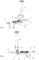
- the setting device comprises a drive device 150 with a transmission element 200 mounted on a holding element 500 to be rotatable about a displacement axis X , an actuating element 300 which is mechanically engaged with the transmission element 200 by means of a connection , the actuating element 300 having a threaded section 350 and is also set up to engage the optically relevant structural units by means of a first and a second coupling element 361, 362 , and a guide part 400 which can be attached to the holding element 500 and has a mating thread corresponding to the threaded section 350 , the adjusting element 300 being connected to the threaded section 350 attachable guide part 400, which in combination with the threaded section 350 is set up to convert a rotary movement of the transmission element 200 into a sliding movement along the displacement axis X, in the guide part 400 is rotatable and displaceable gel is agert.
- the first and the second coupling member 361, 362 is formed in the examples shown, by a concentrically arranged to the displacement axis X spherical head, it being possible for the first and the second coupling member 361, 362 formed as a releasable by the actuating element 300 screws.
- the drive device 150 which can preferably be mounted on a headlight housing, can be actuated manually, for example, and includes in the figures Embodiments shown an adjusting screw 600, the rotational movement is converted in a known manner into a rotational movement of a transmission element 200 which is rotatably mounted about a displacement axis X.
- the axis of rotation of the adjusting screw 600 is oriented to the displacement axis X such that the adjusting screw 600 of a motor vehicle headlight that is installed in a vehicle is still accessible.
- the axis of rotation of the adjusting screw 600 can have any angle with respect to the displacement axis X.
- the axis of rotation of the adjusting screw 600 is at an angle between 80 ° and 100 ° with respect to the displacement axis X.
- the axis of rotation of the adjusting screw 600 is oriented normal to the displacement axis X.
- the transmission element 200 also has a toothing, in particular a ring gear, the adjusting screw 600 being provided for engagement in the toothing.
- the transmission element 200 also has an opening into which the actuating element 300 is inserted.
- the actuating element can be rotated 300 about a displacement axis X, that is, that the adjusting element 300 also is with twisted during a rotational movement of the transmission element 200th
- the adjusting rod is also 300 in Fig. 1 and formed in the other figures as an actuating rod and has a threaded portion 350 by means of which the adjusting element 300 with a one to the threaded portion 350 of the actuator element 300 corresponding counter-thread exhibiting guide part is mounted rotatably about its longitudinal axis or the displacement axis X 400, wherein the guide portion 400 is fixedly arranged on the holding element 500 with respect to the drive device 150 .
- the guide part 400 is fastened detachably or interchangeably to the holding element 500 .
- the holding element 500 is, for example, firmly connected to a motor vehicle headlight housing and is screwed on, for example, by means of screws.
- the holding element 500 also identifies in the example 1 and 2 a first and a second stop 510, 520, which are arranged in connection with two of the actuating element 300, radially protruding to the displacement axis X projections 310 limit the pushing movement of the control element 300 along the displacement axis X.
- 3 and 4 show another example of an adjuster, but without the aforementioned stops 510, 520 and protrusions 310 of the example 1 and 2 ,
Landscapes
- Engineering & Computer Science (AREA)
- General Engineering & Computer Science (AREA)
- Mechanical Engineering (AREA)
- Non-Portable Lighting Devices Or Systems Thereof (AREA)
- Lighting Device Outwards From Vehicle And Optical Signal (AREA)
Priority Applications (3)
| Application Number | Priority Date | Filing Date | Title |
|---|---|---|---|
| EP18191005.0A EP3616992B1 (fr) | 2018-08-27 | 2018-08-27 | Dispositif de réglage pour un phare de véhicule automobile |
| KR1020190096903A KR102267266B1 (ko) | 2018-08-27 | 2019-08-08 | 자동차 헤드램프용 설정 장치 |
| CN201910794925.0A CN110864263B (zh) | 2018-08-27 | 2019-08-27 | 用于机动车探照灯的调节装置 |
Applications Claiming Priority (1)
| Application Number | Priority Date | Filing Date | Title |
|---|---|---|---|
| EP18191005.0A EP3616992B1 (fr) | 2018-08-27 | 2018-08-27 | Dispositif de réglage pour un phare de véhicule automobile |
Publications (2)
| Publication Number | Publication Date |
|---|---|
| EP3616992A1 true EP3616992A1 (fr) | 2020-03-04 |
| EP3616992B1 EP3616992B1 (fr) | 2021-03-10 |
Family
ID=63490211
Family Applications (1)
| Application Number | Title | Priority Date | Filing Date |
|---|---|---|---|
| EP18191005.0A Active EP3616992B1 (fr) | 2018-08-27 | 2018-08-27 | Dispositif de réglage pour un phare de véhicule automobile |
Country Status (3)
| Country | Link |
|---|---|
| EP (1) | EP3616992B1 (fr) |
| KR (1) | KR102267266B1 (fr) |
| CN (1) | CN110864263B (fr) |
Cited By (2)
| Publication number | Priority date | Publication date | Assignee | Title |
|---|---|---|---|---|
| WO2023156189A1 (fr) * | 2022-02-15 | 2023-08-24 | HELLA GmbH & Co. KGaA | Arbre souple pour une unité de réglage dans un phare et procédé de fabrication |
| EP4226056A4 (fr) * | 2020-10-05 | 2024-03-27 | Asyst Tech L P | Biellette de transmission réglable |
Citations (6)
| Publication number | Priority date | Publication date | Assignee | Title |
|---|---|---|---|---|
| DE102011017538A1 (de) * | 2011-04-26 | 2012-10-31 | Automotive Lighting Reutlingen Gmbh | Kompakte vertikale Verstelleinheit für Scheinwerfer mit überlagerter horizontaler Grundeinstellung |
| CN104296093A (zh) * | 2014-09-05 | 2015-01-21 | 上海小糸车灯有限公司 | 一种用于车灯可调支架连接的双球头连杆连接装置 |
| EP2881283A1 (fr) * | 2013-11-28 | 2015-06-10 | Automotive Lighting Reutlingen GmbH | Phare de véhicule automobile |
| DE102014200237A1 (de) * | 2014-01-09 | 2015-07-09 | Automotive Lighting Reutlingen Gmbh | Scheinwerfer eines Kraftfahrzeugs |
| FR3022984A1 (fr) * | 2014-06-27 | 2016-01-01 | Valeo Iluminacion Sa | Dispositif de reglage de l'inclinaison d'un reflecteur |
| DE202015106575U1 (de) * | 2014-12-08 | 2016-01-07 | Ford Global Technologies, Llc | Einstellvorrichtung zum Ausrichten von zwei entgegengesetzt geschwenkten Lampenelementen eines Kraftfahrzeugs |
Family Cites Families (16)
| Publication number | Priority date | Publication date | Assignee | Title |
|---|---|---|---|---|
| DE3728121A1 (de) * | 1987-08-22 | 1989-03-02 | Bosch Gmbh Robert | Kugelzapfenlagerung eines reflektors an rahmen von kraftfahrzeugscheinwerfern |
| US5779343A (en) * | 1996-06-25 | 1998-07-14 | Elco Industries | Headlight adjuster |
| US6527427B1 (en) * | 2000-10-14 | 2003-03-04 | Asyst Technologies, Llc | Clutching feature for adjusting device |
| DE10133864C1 (de) * | 2001-07-12 | 2002-10-10 | Daimler Chrysler Ag | Kraftfahrzeugscheinwerfer mit getrennt einstellbaren Reflektoren für unterschiedliche Lichtfunktionen und Verfahren zum Einstellen der Lichtabstrahlung desselben |
| DE10336628A1 (de) * | 2003-08-05 | 2005-03-24 | Thyssenkrupp Presta Steertec Gmbh | Lenkgetriebe für ein Kraftfahrzeug |
| JP4796364B2 (ja) * | 2005-09-15 | 2011-10-19 | 川崎重工業株式会社 | 車両のランプ装置およびこれを備えた自動二輪車 |
| DE102010061105A1 (de) * | 2010-12-08 | 2012-06-14 | Hella Kgaa Hueck & Co. | Scheinwerfer für ein Fahrzeug mit einer Justageverbingung zwischen zwei Lichteinheiten |
| AT514113B1 (de) * | 2013-04-04 | 2019-08-15 | Zkw Group Gmbh | Fahrzeugscheinwerfer mit einer Verstelleinrichtung |
| AT515268B1 (de) * | 2013-12-20 | 2015-10-15 | Zizala Lichtsysteme Gmbh | Beleuchtungsvorrichtung für einen Kraftfahrzeugscheinwerfer sowie Kraftfahrzeugscheinwerfer |
| AT515451B1 (de) * | 2014-03-10 | 2016-02-15 | Zizala Lichtsysteme Gmbh | Einstellvorrichtung für einen Fahrzeugscheinwerfer |
| AT516973B1 (de) * | 2015-03-17 | 2017-06-15 | Zkw Group Gmbh | Einstellsystem für einen fahrzeugscheinwerfer |
| DE102015110553A1 (de) * | 2015-07-01 | 2017-01-05 | Hella Kgaa Hueck & Co. | Scheinwerfer für ein Kraftfahrzeug |
| AT517523B1 (de) * | 2015-07-28 | 2017-09-15 | Zkw Group Gmbh | Leuchteinrichtung für einen KFZ-Scheinwerfer |
| CN107458302B (zh) * | 2016-06-03 | 2019-11-22 | 北汽福田汽车股份有限公司 | 用于车辆的大灯组件及具有其的车辆 |
| AT519210B1 (de) * | 2016-10-03 | 2019-03-15 | Zkw Group Gmbh | Beleuchtungseinrichtung für einspurige Kraftfahrzeuge |
| CN207555486U (zh) * | 2017-10-10 | 2018-06-29 | 艾默林汽车活动组件(无锡)有限公司 | 一种电动调节机构及车灯调节装置 |
-
2018
- 2018-08-27 EP EP18191005.0A patent/EP3616992B1/fr active Active
-
2019
- 2019-08-08 KR KR1020190096903A patent/KR102267266B1/ko active IP Right Grant
- 2019-08-27 CN CN201910794925.0A patent/CN110864263B/zh active Active
Patent Citations (6)
| Publication number | Priority date | Publication date | Assignee | Title |
|---|---|---|---|---|
| DE102011017538A1 (de) * | 2011-04-26 | 2012-10-31 | Automotive Lighting Reutlingen Gmbh | Kompakte vertikale Verstelleinheit für Scheinwerfer mit überlagerter horizontaler Grundeinstellung |
| EP2881283A1 (fr) * | 2013-11-28 | 2015-06-10 | Automotive Lighting Reutlingen GmbH | Phare de véhicule automobile |
| DE102014200237A1 (de) * | 2014-01-09 | 2015-07-09 | Automotive Lighting Reutlingen Gmbh | Scheinwerfer eines Kraftfahrzeugs |
| FR3022984A1 (fr) * | 2014-06-27 | 2016-01-01 | Valeo Iluminacion Sa | Dispositif de reglage de l'inclinaison d'un reflecteur |
| CN104296093A (zh) * | 2014-09-05 | 2015-01-21 | 上海小糸车灯有限公司 | 一种用于车灯可调支架连接的双球头连杆连接装置 |
| DE202015106575U1 (de) * | 2014-12-08 | 2016-01-07 | Ford Global Technologies, Llc | Einstellvorrichtung zum Ausrichten von zwei entgegengesetzt geschwenkten Lampenelementen eines Kraftfahrzeugs |
Cited By (2)
| Publication number | Priority date | Publication date | Assignee | Title |
|---|---|---|---|---|
| EP4226056A4 (fr) * | 2020-10-05 | 2024-03-27 | Asyst Tech L P | Biellette de transmission réglable |
| WO2023156189A1 (fr) * | 2022-02-15 | 2023-08-24 | HELLA GmbH & Co. KGaA | Arbre souple pour une unité de réglage dans un phare et procédé de fabrication |
Also Published As
| Publication number | Publication date |
|---|---|
| KR102267266B1 (ko) | 2021-06-22 |
| CN110864263A (zh) | 2020-03-06 |
| CN110864263B (zh) | 2022-04-15 |
| EP3616992B1 (fr) | 2021-03-10 |
| KR20200024086A (ko) | 2020-03-06 |
Similar Documents
| Publication | Publication Date | Title |
|---|---|---|
| EP3616993B1 (fr) | Phare de véhicule automobile avec dispositif de réglage | |
| EP2918447B1 (fr) | Dispositif de réglage pour un phare de véhicule | |
| EP2786897B1 (fr) | Phare de véhicule avec un dispositif de réglage | |
| EP2762358B1 (fr) | Système de réglage de phare de véhicule | |
| EP3069931B1 (fr) | Système de réglage de phare de véhicule | |
| EP3616992B1 (fr) | Dispositif de réglage pour un phare de véhicule automobile | |
| AT508605B1 (de) | Verstellvorrichtung zum verstellen eines optisch relevanten bauteiles eines fahrzeugscheinwerfers | |
| EP3561364A1 (fr) | Dispositif d'ajustement d'un angle de caméra ainsi qu'utilisation d'un tel dispositif | |
| EP2697562B1 (fr) | Dispositif pour régler un tube optique disposé dans le logement d'un projecteur ou d'un appareil optique | |
| EP3566902B1 (fr) | Dispositif de réglage pour un phare de véhicule automobile | |
| EP4094049A1 (fr) | Dispositif de positionnement pour faire pivoter au moins un composant concerné pour un projecteur de véhicule automobile | |
| AT513203B1 (de) | Verstelleinrichtung für einen Kraftfahrzeugscheinwerfer sowie Kraftfahrzeugscheinwerfer | |
| DE102013213254A1 (de) | Betätigungseinheit für ein optisches element mit zweidimensionalem stellantrieb | |
| DE202020005947U1 (de) | Einstellvorrichtung zur Einstellung einer optisch relevanten Baueinheit eines Kraftfahrzeugscheinwerfers | |
| DE102018132919A1 (de) | Strahlaufweiter und Verfahren zum Betreiben eines Strahlaufweiters | |
| AT510453B1 (de) | Verstellvorrichtung zum verstellen eines optisch relevanten bauteiles eines fahrzeugscheinwerfers | |
| AT506090B1 (de) | Verstellbare lampenhalterung | |
| EP3898326B1 (fr) | Dispositif de réglage pour un phare de véhicule automobile | |
| AT516966B1 (de) | Verstelleinrichtung für Kraftfahrzeugscheinwerfer | |
| EP3538952A1 (fr) | Adaptateur pour faire pivoter un objectif | |
| DE102020108831A1 (de) | Befestigungssystem zum Anbringen eines Projektors in einer Flugzeugkabine, Verfahren zum Warten und/oder Anbringen eines Projektors sowie Verfahren zum Einstellen eines Projektors | |
| WO2016141925A1 (fr) | Projecteur pour véhicules | |
| DE102009019121A1 (de) | Positionierhilfe für verstellbares optisches Element | |
| DE1116916B (de) | Objektivfernfeineinstellvorrichtung fuer kinematografische und fotografische Geraete |
Legal Events
| Date | Code | Title | Description |
|---|---|---|---|
| PUAI | Public reference made under article 153(3) epc to a published international application that has entered the european phase |
Free format text: ORIGINAL CODE: 0009012 |
|
| STAA | Information on the status of an ep patent application or granted ep patent |
Free format text: STATUS: THE APPLICATION HAS BEEN PUBLISHED |
|
| AK | Designated contracting states |
Kind code of ref document: A1 Designated state(s): AL AT BE BG CH CY CZ DE DK EE ES FI FR GB GR HR HU IE IS IT LI LT LU LV MC MK MT NL NO PL PT RO RS SE SI SK SM TR |
|
| AX | Request for extension of the european patent |
Extension state: BA ME |
|
| STAA | Information on the status of an ep patent application or granted ep patent |
Free format text: STATUS: REQUEST FOR EXAMINATION WAS MADE |
|
| 17P | Request for examination filed |
Effective date: 20200902 |
|
| RBV | Designated contracting states (corrected) |
Designated state(s): AL AT BE BG CH CY CZ DE DK EE ES FI FR GB GR HR HU IE IS IT LI LT LU LV MC MK MT NL NO PL PT RO RS SE SI SK SM TR |
|
| GRAP | Despatch of communication of intention to grant a patent |
Free format text: ORIGINAL CODE: EPIDOSNIGR1 |
|
| STAA | Information on the status of an ep patent application or granted ep patent |
Free format text: STATUS: GRANT OF PATENT IS INTENDED |
|
| INTG | Intention to grant announced |
Effective date: 20201013 |
|
| GRAS | Grant fee paid |
Free format text: ORIGINAL CODE: EPIDOSNIGR3 |
|
| STAA | Information on the status of an ep patent application or granted ep patent |
Free format text: STATUS: GRANT OF PATENT IS INTENDED |
|
| GRAA | (expected) grant |
Free format text: ORIGINAL CODE: 0009210 |
|
| STAA | Information on the status of an ep patent application or granted ep patent |
Free format text: STATUS: THE PATENT HAS BEEN GRANTED |
|
| AK | Designated contracting states |
Kind code of ref document: B1 Designated state(s): AL AT BE BG CH CY CZ DE DK EE ES FI FR GB GR HR HU IE IS IT LI LT LU LV MC MK MT NL NO PL PT RO RS SE SI SK SM TR |
|
| REG | Reference to a national code |
Ref country code: GB Ref legal event code: FG4D Free format text: NOT ENGLISH |
|
| REG | Reference to a national code |
Ref country code: AT Ref legal event code: REF Ref document number: 1369471 Country of ref document: AT Kind code of ref document: T Effective date: 20210315 Ref country code: CH Ref legal event code: EP |
|
| REG | Reference to a national code |
Ref country code: IE Ref legal event code: FG4D Free format text: LANGUAGE OF EP DOCUMENT: GERMAN |
|
| REG | Reference to a national code |
Ref country code: DE Ref legal event code: R096 Ref document number: 502018004227 Country of ref document: DE |
|
| REG | Reference to a national code |
Ref country code: LT Ref legal event code: MG9D |
|
| PG25 | Lapsed in a contracting state [announced via postgrant information from national office to epo] |
Ref country code: FI Free format text: LAPSE BECAUSE OF FAILURE TO SUBMIT A TRANSLATION OF THE DESCRIPTION OR TO PAY THE FEE WITHIN THE PRESCRIBED TIME-LIMIT Effective date: 20210310 Ref country code: HR Free format text: LAPSE BECAUSE OF FAILURE TO SUBMIT A TRANSLATION OF THE DESCRIPTION OR TO PAY THE FEE WITHIN THE PRESCRIBED TIME-LIMIT Effective date: 20210310 Ref country code: GR Free format text: LAPSE BECAUSE OF FAILURE TO SUBMIT A TRANSLATION OF THE DESCRIPTION OR TO PAY THE FEE WITHIN THE PRESCRIBED TIME-LIMIT Effective date: 20210611 Ref country code: BG Free format text: LAPSE BECAUSE OF FAILURE TO SUBMIT A TRANSLATION OF THE DESCRIPTION OR TO PAY THE FEE WITHIN THE PRESCRIBED TIME-LIMIT Effective date: 20210610 Ref country code: NO Free format text: LAPSE BECAUSE OF FAILURE TO SUBMIT A TRANSLATION OF THE DESCRIPTION OR TO PAY THE FEE WITHIN THE PRESCRIBED TIME-LIMIT Effective date: 20210610 Ref country code: LT Free format text: LAPSE BECAUSE OF FAILURE TO SUBMIT A TRANSLATION OF THE DESCRIPTION OR TO PAY THE FEE WITHIN THE PRESCRIBED TIME-LIMIT Effective date: 20210310 |
|
| REG | Reference to a national code |
Ref country code: NL Ref legal event code: MP Effective date: 20210310 |
|
| PG25 | Lapsed in a contracting state [announced via postgrant information from national office to epo] |
Ref country code: SE Free format text: LAPSE BECAUSE OF FAILURE TO SUBMIT A TRANSLATION OF THE DESCRIPTION OR TO PAY THE FEE WITHIN THE PRESCRIBED TIME-LIMIT Effective date: 20210310 Ref country code: LV Free format text: LAPSE BECAUSE OF FAILURE TO SUBMIT A TRANSLATION OF THE DESCRIPTION OR TO PAY THE FEE WITHIN THE PRESCRIBED TIME-LIMIT Effective date: 20210310 Ref country code: RS Free format text: LAPSE BECAUSE OF FAILURE TO SUBMIT A TRANSLATION OF THE DESCRIPTION OR TO PAY THE FEE WITHIN THE PRESCRIBED TIME-LIMIT Effective date: 20210310 |
|
| PG25 | Lapsed in a contracting state [announced via postgrant information from national office to epo] |
Ref country code: NL Free format text: LAPSE BECAUSE OF FAILURE TO SUBMIT A TRANSLATION OF THE DESCRIPTION OR TO PAY THE FEE WITHIN THE PRESCRIBED TIME-LIMIT Effective date: 20210310 |
|
| PG25 | Lapsed in a contracting state [announced via postgrant information from national office to epo] |
Ref country code: CZ Free format text: LAPSE BECAUSE OF FAILURE TO SUBMIT A TRANSLATION OF THE DESCRIPTION OR TO PAY THE FEE WITHIN THE PRESCRIBED TIME-LIMIT Effective date: 20210310 Ref country code: EE Free format text: LAPSE BECAUSE OF FAILURE TO SUBMIT A TRANSLATION OF THE DESCRIPTION OR TO PAY THE FEE WITHIN THE PRESCRIBED TIME-LIMIT Effective date: 20210310 Ref country code: SM Free format text: LAPSE BECAUSE OF FAILURE TO SUBMIT A TRANSLATION OF THE DESCRIPTION OR TO PAY THE FEE WITHIN THE PRESCRIBED TIME-LIMIT Effective date: 20210310 |
|
| PG25 | Lapsed in a contracting state [announced via postgrant information from national office to epo] |
Ref country code: PT Free format text: LAPSE BECAUSE OF FAILURE TO SUBMIT A TRANSLATION OF THE DESCRIPTION OR TO PAY THE FEE WITHIN THE PRESCRIBED TIME-LIMIT Effective date: 20210712 Ref country code: PL Free format text: LAPSE BECAUSE OF FAILURE TO SUBMIT A TRANSLATION OF THE DESCRIPTION OR TO PAY THE FEE WITHIN THE PRESCRIBED TIME-LIMIT Effective date: 20210310 Ref country code: RO Free format text: LAPSE BECAUSE OF FAILURE TO SUBMIT A TRANSLATION OF THE DESCRIPTION OR TO PAY THE FEE WITHIN THE PRESCRIBED TIME-LIMIT Effective date: 20210310 Ref country code: SK Free format text: LAPSE BECAUSE OF FAILURE TO SUBMIT A TRANSLATION OF THE DESCRIPTION OR TO PAY THE FEE WITHIN THE PRESCRIBED TIME-LIMIT Effective date: 20210310 Ref country code: IS Free format text: LAPSE BECAUSE OF FAILURE TO SUBMIT A TRANSLATION OF THE DESCRIPTION OR TO PAY THE FEE WITHIN THE PRESCRIBED TIME-LIMIT Effective date: 20210710 |
|
| REG | Reference to a national code |
Ref country code: DE Ref legal event code: R097 Ref document number: 502018004227 Country of ref document: DE |
|
| PLBE | No opposition filed within time limit |
Free format text: ORIGINAL CODE: 0009261 |
|
| STAA | Information on the status of an ep patent application or granted ep patent |
Free format text: STATUS: NO OPPOSITION FILED WITHIN TIME LIMIT |
|
| PG25 | Lapsed in a contracting state [announced via postgrant information from national office to epo] |
Ref country code: DK Free format text: LAPSE BECAUSE OF FAILURE TO SUBMIT A TRANSLATION OF THE DESCRIPTION OR TO PAY THE FEE WITHIN THE PRESCRIBED TIME-LIMIT Effective date: 20210310 Ref country code: AL Free format text: LAPSE BECAUSE OF FAILURE TO SUBMIT A TRANSLATION OF THE DESCRIPTION OR TO PAY THE FEE WITHIN THE PRESCRIBED TIME-LIMIT Effective date: 20210310 Ref country code: ES Free format text: LAPSE BECAUSE OF FAILURE TO SUBMIT A TRANSLATION OF THE DESCRIPTION OR TO PAY THE FEE WITHIN THE PRESCRIBED TIME-LIMIT Effective date: 20210310 |
|
| 26N | No opposition filed |
Effective date: 20211213 |
|
| PG25 | Lapsed in a contracting state [announced via postgrant information from national office to epo] |
Ref country code: SI Free format text: LAPSE BECAUSE OF FAILURE TO SUBMIT A TRANSLATION OF THE DESCRIPTION OR TO PAY THE FEE WITHIN THE PRESCRIBED TIME-LIMIT Effective date: 20210310 |
|
| REG | Reference to a national code |
Ref country code: CH Ref legal event code: PL |
|
| PG25 | Lapsed in a contracting state [announced via postgrant information from national office to epo] |
Ref country code: MC Free format text: LAPSE BECAUSE OF FAILURE TO SUBMIT A TRANSLATION OF THE DESCRIPTION OR TO PAY THE FEE WITHIN THE PRESCRIBED TIME-LIMIT Effective date: 20210310 |
|
| REG | Reference to a national code |
Ref country code: BE Ref legal event code: MM Effective date: 20210831 |
|
| PG25 | Lapsed in a contracting state [announced via postgrant information from national office to epo] |
Ref country code: LI Free format text: LAPSE BECAUSE OF NON-PAYMENT OF DUE FEES Effective date: 20210831 Ref country code: IT Free format text: LAPSE BECAUSE OF FAILURE TO SUBMIT A TRANSLATION OF THE DESCRIPTION OR TO PAY THE FEE WITHIN THE PRESCRIBED TIME-LIMIT Effective date: 20210310 Ref country code: CH Free format text: LAPSE BECAUSE OF NON-PAYMENT OF DUE FEES Effective date: 20210831 |
|
| PG25 | Lapsed in a contracting state [announced via postgrant information from national office to epo] |
Ref country code: IS Free format text: LAPSE BECAUSE OF FAILURE TO SUBMIT A TRANSLATION OF THE DESCRIPTION OR TO PAY THE FEE WITHIN THE PRESCRIBED TIME-LIMIT Effective date: 20210710 Ref country code: LU Free format text: LAPSE BECAUSE OF NON-PAYMENT OF DUE FEES Effective date: 20210827 |
|
| PG25 | Lapsed in a contracting state [announced via postgrant information from national office to epo] |
Ref country code: IE Free format text: LAPSE BECAUSE OF NON-PAYMENT OF DUE FEES Effective date: 20210827 Ref country code: BE Free format text: LAPSE BECAUSE OF NON-PAYMENT OF DUE FEES Effective date: 20210831 |
|
| GBPC | Gb: european patent ceased through non-payment of renewal fee |
Effective date: 20220827 |
|
| PG25 | Lapsed in a contracting state [announced via postgrant information from national office to epo] |
Ref country code: CY Free format text: LAPSE BECAUSE OF FAILURE TO SUBMIT A TRANSLATION OF THE DESCRIPTION OR TO PAY THE FEE WITHIN THE PRESCRIBED TIME-LIMIT Effective date: 20210310 |
|
| P01 | Opt-out of the competence of the unified patent court (upc) registered |
Effective date: 20230528 |
|
| PG25 | Lapsed in a contracting state [announced via postgrant information from national office to epo] |
Ref country code: HU Free format text: LAPSE BECAUSE OF FAILURE TO SUBMIT A TRANSLATION OF THE DESCRIPTION OR TO PAY THE FEE WITHIN THE PRESCRIBED TIME-LIMIT; INVALID AB INITIO Effective date: 20180827 |
|
| PG25 | Lapsed in a contracting state [announced via postgrant information from national office to epo] |
Ref country code: GB Free format text: LAPSE BECAUSE OF NON-PAYMENT OF DUE FEES Effective date: 20220827 |
|
| PGFP | Annual fee paid to national office [announced via postgrant information from national office to epo] |
Ref country code: FR Payment date: 20230828 Year of fee payment: 6 Ref country code: DE Payment date: 20230821 Year of fee payment: 6 |
|
| PG25 | Lapsed in a contracting state [announced via postgrant information from national office to epo] |
Ref country code: MK Free format text: LAPSE BECAUSE OF FAILURE TO SUBMIT A TRANSLATION OF THE DESCRIPTION OR TO PAY THE FEE WITHIN THE PRESCRIBED TIME-LIMIT Effective date: 20210310 |