EP3608901B1 - Verschiebungspufferschaltung, gate-treiberschaltung, anzeigetafel, anzeigevorrichtung und ansteuerungsverfahren - Google Patents
Verschiebungspufferschaltung, gate-treiberschaltung, anzeigetafel, anzeigevorrichtung und ansteuerungsverfahren Download PDFInfo
- Publication number
- EP3608901B1 EP3608901B1 EP17861186.9A EP17861186A EP3608901B1 EP 3608901 B1 EP3608901 B1 EP 3608901B1 EP 17861186 A EP17861186 A EP 17861186A EP 3608901 B1 EP3608901 B1 EP 3608901B1
- Authority
- EP
- European Patent Office
- Prior art keywords
- shift
- buffer
- transistor
- pull
- circuit
- Prior art date
- Legal status (The legal status is an assumption and is not a legal conclusion. Google has not performed a legal analysis and makes no representation as to the accuracy of the status listed.)
- Active
Links
- 239000000872 buffer Substances 0.000 title claims description 535
- 238000000034 method Methods 0.000 title claims description 13
- 101100102583 Schizosaccharomyces pombe (strain 972 / ATCC 24843) vgl1 gene Proteins 0.000 claims description 29
- 102100023478 Transcription cofactor vestigial-like protein 1 Human genes 0.000 claims description 29
- 239000003990 capacitor Substances 0.000 claims description 22
- 101100102598 Mus musculus Vgll2 gene Proteins 0.000 claims description 20
- 102100023477 Transcription cofactor vestigial-like protein 2 Human genes 0.000 claims description 20
- 102100036285 25-hydroxyvitamin D-1 alpha hydroxylase, mitochondrial Human genes 0.000 claims description 14
- 101000875403 Homo sapiens 25-hydroxyvitamin D-1 alpha hydroxylase, mitochondrial Proteins 0.000 claims description 14
- 230000004044 response Effects 0.000 claims description 10
- 238000010586 diagram Methods 0.000 description 16
- 101150028119 SPD1 gene Proteins 0.000 description 13
- 230000008859 change Effects 0.000 description 4
- 238000005516 engineering process Methods 0.000 description 4
- 238000004519 manufacturing process Methods 0.000 description 3
- 230000008569 process Effects 0.000 description 3
- 230000000694 effects Effects 0.000 description 2
- 230000002159 abnormal effect Effects 0.000 description 1
- 239000002131 composite material Substances 0.000 description 1
- 230000002349 favourable effect Effects 0.000 description 1
- 230000005669 field effect Effects 0.000 description 1
- 230000010354 integration Effects 0.000 description 1
- 239000000463 material Substances 0.000 description 1
- 238000012986 modification Methods 0.000 description 1
- 230000004048 modification Effects 0.000 description 1
- 238000001259 photo etching Methods 0.000 description 1
- 239000000758 substrate Substances 0.000 description 1
- 239000010409 thin film Substances 0.000 description 1
Images


Classifications
-
- G—PHYSICS
- G09—EDUCATION; CRYPTOGRAPHY; DISPLAY; ADVERTISING; SEALS
- G09G—ARRANGEMENTS OR CIRCUITS FOR CONTROL OF INDICATING DEVICES USING STATIC MEANS TO PRESENT VARIABLE INFORMATION
- G09G3/00—Control arrangements or circuits, of interest only in connection with visual indicators other than cathode-ray tubes
- G09G3/20—Control arrangements or circuits, of interest only in connection with visual indicators other than cathode-ray tubes for presentation of an assembly of a number of characters, e.g. a page, by composing the assembly by combination of individual elements arranged in a matrix no fixed position being assigned to or needed to be assigned to the individual characters or partial characters
- G09G3/34—Control arrangements or circuits, of interest only in connection with visual indicators other than cathode-ray tubes for presentation of an assembly of a number of characters, e.g. a page, by composing the assembly by combination of individual elements arranged in a matrix no fixed position being assigned to or needed to be assigned to the individual characters or partial characters by control of light from an independent source
- G09G3/36—Control arrangements or circuits, of interest only in connection with visual indicators other than cathode-ray tubes for presentation of an assembly of a number of characters, e.g. a page, by composing the assembly by combination of individual elements arranged in a matrix no fixed position being assigned to or needed to be assigned to the individual characters or partial characters by control of light from an independent source using liquid crystals
- G09G3/3611—Control of matrices with row and column drivers
- G09G3/3674—Details of drivers for scan electrodes
- G09G3/3677—Details of drivers for scan electrodes suitable for active matrices only
-
- G—PHYSICS
- G11—INFORMATION STORAGE
- G11C—STATIC STORES
- G11C19/00—Digital stores in which the information is moved stepwise, e.g. shift registers
- G11C19/28—Digital stores in which the information is moved stepwise, e.g. shift registers using semiconductor elements
-
- G—PHYSICS
- G09—EDUCATION; CRYPTOGRAPHY; DISPLAY; ADVERTISING; SEALS
- G09G—ARRANGEMENTS OR CIRCUITS FOR CONTROL OF INDICATING DEVICES USING STATIC MEANS TO PRESENT VARIABLE INFORMATION
- G09G3/00—Control arrangements or circuits, of interest only in connection with visual indicators other than cathode-ray tubes
- G09G3/20—Control arrangements or circuits, of interest only in connection with visual indicators other than cathode-ray tubes for presentation of an assembly of a number of characters, e.g. a page, by composing the assembly by combination of individual elements arranged in a matrix no fixed position being assigned to or needed to be assigned to the individual characters or partial characters
- G09G3/22—Control arrangements or circuits, of interest only in connection with visual indicators other than cathode-ray tubes for presentation of an assembly of a number of characters, e.g. a page, by composing the assembly by combination of individual elements arranged in a matrix no fixed position being assigned to or needed to be assigned to the individual characters or partial characters using controlled light sources
- G09G3/30—Control arrangements or circuits, of interest only in connection with visual indicators other than cathode-ray tubes for presentation of an assembly of a number of characters, e.g. a page, by composing the assembly by combination of individual elements arranged in a matrix no fixed position being assigned to or needed to be assigned to the individual characters or partial characters using controlled light sources using electroluminescent panels
- G09G3/32—Control arrangements or circuits, of interest only in connection with visual indicators other than cathode-ray tubes for presentation of an assembly of a number of characters, e.g. a page, by composing the assembly by combination of individual elements arranged in a matrix no fixed position being assigned to or needed to be assigned to the individual characters or partial characters using controlled light sources using electroluminescent panels semiconductive, e.g. using light-emitting diodes [LED]
- G09G3/3208—Control arrangements or circuits, of interest only in connection with visual indicators other than cathode-ray tubes for presentation of an assembly of a number of characters, e.g. a page, by composing the assembly by combination of individual elements arranged in a matrix no fixed position being assigned to or needed to be assigned to the individual characters or partial characters using controlled light sources using electroluminescent panels semiconductive, e.g. using light-emitting diodes [LED] organic, e.g. using organic light-emitting diodes [OLED]
- G09G3/3266—Details of drivers for scan electrodes
-
- G—PHYSICS
- G11—INFORMATION STORAGE
- G11C—STATIC STORES
- G11C19/00—Digital stores in which the information is moved stepwise, e.g. shift registers
- G11C19/18—Digital stores in which the information is moved stepwise, e.g. shift registers using capacitors as main elements of the stages
- G11C19/182—Digital stores in which the information is moved stepwise, e.g. shift registers using capacitors as main elements of the stages in combination with semiconductor elements, e.g. bipolar transistors, diodes
- G11C19/184—Digital stores in which the information is moved stepwise, e.g. shift registers using capacitors as main elements of the stages in combination with semiconductor elements, e.g. bipolar transistors, diodes with field-effect transistors, e.g. MOS-FET
-
- G—PHYSICS
- G09—EDUCATION; CRYPTOGRAPHY; DISPLAY; ADVERTISING; SEALS
- G09G—ARRANGEMENTS OR CIRCUITS FOR CONTROL OF INDICATING DEVICES USING STATIC MEANS TO PRESENT VARIABLE INFORMATION
- G09G2300/00—Aspects of the constitution of display devices
- G09G2300/04—Structural and physical details of display devices
- G09G2300/0404—Matrix technologies
- G09G2300/0408—Integration of the drivers onto the display substrate
-
- G—PHYSICS
- G09—EDUCATION; CRYPTOGRAPHY; DISPLAY; ADVERTISING; SEALS
- G09G—ARRANGEMENTS OR CIRCUITS FOR CONTROL OF INDICATING DEVICES USING STATIC MEANS TO PRESENT VARIABLE INFORMATION
- G09G2310/00—Command of the display device
- G09G2310/02—Addressing, scanning or driving the display screen or processing steps related thereto
- G09G2310/0264—Details of driving circuits
- G09G2310/0267—Details of drivers for scan electrodes, other than drivers for liquid crystal, plasma or OLED displays
-
- G—PHYSICS
- G09—EDUCATION; CRYPTOGRAPHY; DISPLAY; ADVERTISING; SEALS
- G09G—ARRANGEMENTS OR CIRCUITS FOR CONTROL OF INDICATING DEVICES USING STATIC MEANS TO PRESENT VARIABLE INFORMATION
- G09G2310/00—Command of the display device
- G09G2310/02—Addressing, scanning or driving the display screen or processing steps related thereto
- G09G2310/0264—Details of driving circuits
- G09G2310/0286—Details of a shift registers arranged for use in a driving circuit
-
- G—PHYSICS
- G09—EDUCATION; CRYPTOGRAPHY; DISPLAY; ADVERTISING; SEALS
- G09G—ARRANGEMENTS OR CIRCUITS FOR CONTROL OF INDICATING DEVICES USING STATIC MEANS TO PRESENT VARIABLE INFORMATION
- G09G2310/00—Command of the display device
- G09G2310/02—Addressing, scanning or driving the display screen or processing steps related thereto
- G09G2310/0264—Details of driving circuits
- G09G2310/0291—Details of output amplifiers or buffers arranged for use in a driving circuit
Definitions
- Embodiments of the present disclosure relate to a shift-buffer circuit, a gate driving circuit, a display panel, a display device and a driving method.
- a Gate-driver on Array (GOA) technology is to integrate a gate driving circuit directly on an array substrate of a display device by a photoetching process
- a GOA circuit usually includes a plurality of cascaded shift registers, and each of the shift registers corresponds to a gate line corresponding to a row of pixels (for example, each of the shift registers provides a scan driving signal to a gate line corresponding to a row of pixels), so as to realize scan driving of the display panel.
- CN 105788555 A describes a shift register unit and a driving method thereof, a gate driving circuit, and a display device are disclosed.
- US 2010/245337A1 describes a shift register and a gate-line drive device therefor are disclosed.
- Embodiments of the disclosure provide a shift-buffer circuit, comprising: a shift register and a plurality of buffers connected with the shift register, wherein: the shift register includes a shift output terminal; the shift register is configured to output a shift output signal from the shift output terminal, in response to a shift clock signal; each of the buffers includes a buffer input terminal and a buffer output terminal, the buffer input terminal being connected with the shift output terminal; and each of the buffers is configured to output a buffer output signal from the buffer output terminal, in response to a buffer clock signal; the shift register includes:
- the second power supply terminal is connected with the first power supply terminal.
- the second shift reset circuit includes a seventh shift transistor, a first electrode of the seventh shift transistor being connected with the shift pull-up node, a gate electrode of the seventh shift transistor being connected with the second shift pull-down node, and a second electrode of the seventh shift transistor being connected with the first power supply terminal;
- the second shift output pull-down circuit includes an eighth shift transistor, a first electrode of the eighth shift transistor being connected with the shift output terminal, a gate electrode of the eighth shift transistor being connected with the second shift pull-down node, and a second electrode of the eighth shift transistor being connected with the first power supply terminal;
- the second pull-down node control circuit includes a ninth shift transistor and a tenth shift transistor, a first electrode of the ninth shift transistor being connected with the second power signal terminal, a gate electrode of the ninth shift transistor being connected with the second power signal terminal, a second electrode of the ninth shift transistor being connected with the second shift pull-down node, a first electrode of the tenth shift transistor being connected
- each of the shift registers is connected with four of the buffers.
- Embodiments of the disclosure further provide a gate driving circuit, comprising shift-buffer circuits in a plurality of stages, wherein a shift-buffer circuit of each stage includes the shift-buffer circuit described above.
- a shift output terminal of a shift register in a shift-buffer circuit of a (2n-1)-th stage is connected with a shift input terminal of a shift register in a shift-buffer circuit of a (2n+1)-th stage; and a shift output terminal of a shift register in a shift-buffer circuit of a 2n-th stage is connected with a shift input terminal of a shift register in a shift-buffer circuit of a (2n+2)-th stage, where n is an integer greater than zero.
- an enabled signal terminal of a buffer in the shift-buffer circuit of the (2n-1)-th stage is configured to receive a first enabled signal; and an enabled signal terminal of a buffer in the shift-buffer circuit of the 2n-th stage is configured to receive a second enabled signal.
- Embodiments of the disclosure further provide a display panel, comprising the gate driving circuit described above.
- Embodiments of the disclosure further provide a display device, comprising the display panel described above.
- Embodiments of the disclosure further provide a method of driving the shift-buffer circuit described above, comprising: applying a shift clock signal to a shift register, to make the shift register output a shift output signal in response to the shift clock signal; and applying buffer clock signals to a plurality of buffers in a period of the shift output signal, to make the plurality of buffers output buffer output signals sequentially.
- a resolution of a display panel adopting a conventional gate driving circuit is fixed, the resolution cannot be adjusted according to actual needs, and selective driving cannot be implemented in different regions of the display panel.
- a shift-buffer circuit, a gate driving circuit, a display panel and a driving method provided by embodiments of the present disclosure can change a display resolution and can perform selective driving in different regions of the display panel.
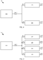
- the shift-buffer circuit 100 comprises: a shift register 110 and a plurality of buffers 120 connected with the shift register 110.
- the shift register 110 includes a shift output terminal SOUT; the shift register 110 is configured to output a shift output signal from the shift output terminal SOUT, in response to a shift clock signal CLKS.
- Each of the buffers 120 includes a buffer input terminal BIN and a buffer output terminal BOUT, and each buffer input terminal BIN is connected with the shift output terminal SOUT; each of the buffers 120 is configured to output a buffer output signal from the buffer output terminal BOUT, in response to a buffer clock signal CLKB.
- the buffer output signal is a gate scanning signal.
- each buffer output signal may be used as a gate scanning signal for driving a row or a column of pixels in a display panel for display.
- the shift-buffer circuit 100 comprises a shift register 110 and two buffers 120 connected with the shift register 110.
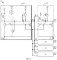
- the shift-buffer circuit 100 comprises a shift register 110 and four buffers 120 connected with the shift register 110. It should be noted that, in the embodiments of the present disclosure, the number of the buffers 120 connected with a shift register 110 is not limited to two or four, and may also be other numbers.
- the shift-buffer circuit 100 comprises a shift register 110 and four buffers 120 connected with the shift register 110, the resolution ratio change and the current leakage situation of the shift-buffer circuit 110 are better balanced.
- the shift-buffer circuit 100 comprises a shift register 110 and four buffers 120 connected with the shift register 110.
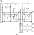
- the shift register 110 comprises a shift input circuit 111, a first shift reset circuit 112, a shift output circuit 113, a first shift output pull-down circuit 114, a first pull-down node control circuit 115, and a shift storage capacitor SC.
- the shift input circuit 111 is connected with a shift input terminal SIN and a shift pull-up node SPU, respectively;
- the first shift reset circuit 112 is connected with the shift pull-up node SPU, a first shift pull-down node SPD1, and a first power supply terminal VGL1, respectively;
- the shift output circuit 113 is connected with the shift pull-up node SPU, a shift clock signal terminal (which is used for providing a shift clock signal CLKS) and the shift output terminal SOUT, respectively;
- the first shift output pull-down circuit 114 is connected with the shift output terminal SOUT, the first pull-down node SPD1 and the first power supply terminal VGL1, respectively;
- the first pull-down node control circuit 115 is connected with the first shift pull-down node SPD1, a first power signal terminal VDD1 and the first power supply terminal VGL1, rcspcctivcly; and
- the shift storage capacitor SC is connected with the shift pull-up node SPU and the shift output terminal SOUT, respectively.
- each buffer 120 includes: a buffer input circuit 121, a first buffer reset circuit 122, a buffer output circuit 123, a first buffer output pull-down circuit 124 and a buffer storage capacitor BC.
- the buffer input circuit 121 is connected with the buffer input terminal BIN and a buffer pull-up node BPU, respectively;
- the first buffer reset circuit 122 is connected with the buffer pull-up node BPU, a first buffer pull-down node BPD1 and a second power supply terminal VGL2, respectively;
- the buffer output circuit 123 is connected with the buffer pull-up node BPU, a buffer clock signal terminal (which is used for providing a buffer clock signal CLKB) and the buffer output terminal BOUT, respectively;
- the first buffer output pull-down circuit 124 is connected with the buffer output terminal BOUT, the first buffer pull-down node BPD1 and a second power supply terminal VGL2, respectively;
- the buffer storage capacitor BC is connected with the buffer pull-up node BPU and the buffer output terminal BOUT, respectively.
- the shift register 110 and the buffer 120 may further include other additional circuits, the shift register 110 in FIG. 3 may be combined with other buffers to form a shift buffer circuit, and the buffer 120 in FIG. 3 may also be combined with other shift registers to form a shift buffer circuit.
- the first buffer pull-down node BPD1 is connected with the first shift pull-down node SPD1. That is, the shift register 110 and the buffer 120 may share the first pull-down node, so that the number of circuits for controlling a voltage of the first pull-down node may be reduced, thereby simplifying the circuit and facilitating design and production of the circuit.
- the first pull-down node which is shared includes the first buffer pull-down node BPD1 and the first shift pull-down node SPD1 which are electrically connected with each other, and thus the voltages of the first buffer pull-down node BPD1 and the first shift pull-down node SPD1 may be controlled by a same circuit.
- a second power supply terminal VGL2 shown in FIG. 5 may be connected with the first power supply terminal VGL1 (a circuit after being connected is shown in FIG. 4 ).
- the second power supply terminal VGL2 is connected with the first power supply terminal VGL1, which may simplify the circuit and facilitate design and production of the circuit.
- a voltage of the first power supply terminal VGL1 is a low level voltage (for example, 0V, -1V or other values), and a voltage of the second power terminal VGL2 is also a low level voltage.
- the shift input circuit 111 includes a first shift transistor T1.
- a first electrode of the first shift transistor T1 is connected with the shift input terminal SIN
- a gate electrode of the first shift transistor T1 is connected with the shift input terminal SIN
- a second electrode of the first shift transistor T1 is connected with the shift pull-up node SPU.
- the first shift reset circuit 112 includes a second shift transistor T2.
- a first electrode of the second shift transistor T2 is connected with the shift pull-up node SPU, a gate electrode of the second shift transistor T2 is connected with the first shift pull-down node SPD1, and a second electrode of the second shift transistor T2 is connected with the first power supply terminal VGL1.
- the shift output circuit 113 includes a third shift transistor T3.
- a first electrode of the third shift transistor T3 is connected with the shift clock signal terminal for receiving a shift clock signal CLKS, a gate electrode of the third shift transistor T3 is connected with the shift pull-up node SPU, a second electrode of the third shift transistor T3 is connected with the shift output terminal SOUT.
- the first shift output pull-down circuit 114 includes a fourth shift transistor T4.
- a first electrode of the fourth shift transistor is connected with the shift output terminal SOUT, a gate electrode of the fourth shift transistor is connected with the first shift pull-down node SPD1, and a second electrode of the fourth shift transistor is connected with the first power supply terminal VGL1.
- the first pull-down node control circuit 115 includes a fifth shift transistor T5 and a sixth shift transistor T6.
- a first electrode of the fifth shift transistor T5 is connected with the first power signal terminal VDD1
- a gate electrode of the fifth transistor T5 is connected with the first power signal terminal VDD1
- a second electrode of the fifth shift transistor T5 is connected with the first shift pull-down node SPD1.
- a first electrode of the sixth shift transistor T6 is connected with the first shift pull-down node SPD1, a gate electrode of the sixth shift transistor T6 is connected with the shift pull-up node SPU, and a second electrode of the sixth shift transistor T6 is connected with the first power supply terminal VGL1.
- a first terminal of the shift storage capacitor SC is connected with the shift pull-up node SPU, and a second terminal of the shift storage capacitor SC is connected with the shift output terminal SOUT.
- the buffer input circuit 121 includes a first buffer transistor M1.
- a first electrode of the first buffer transistor M is connected with the buffer input terminal BIN, a gate electrode of the first buffer transistor M1 is connected with an enabled signal terminal EN, and a second electrode of the first buffer transistor M1 is connected with the buffer pull-up node BPU.
- the first buffer reset circuit 122 includes a second buffer transistor M2.
- a first electrode of the second buffer transistor M2 is connected with the buffer pull-up node BPU, a gate electrode of the second buffer transistor M2 is connected with the first buffer pull-down node BPD1, and a second electrode of the second buffer transistor M2 is connected with the second power supply terminal VGL2.
- the buffer output circuit 123 includes a third buffer transistor M3.
- a first electrode of the third buffer transistor M3 is connected with the buffer clock signal terminal to receive a buffer clock signal CLKB, a gate electrode of the third buffer transistor M3 is connected with the buffer pull-up node BPU, and a second electrode of the third buffer transistor M3 is connected with the buffer output terminal BOUT.
- the first buffer output pull-down circuit 124 includes a fourth buffer transistor M4.
- a first electrode of the fourth buffer transistor M4 is connected with the buffer output terminal BOUT, a gate electrode of the fourth buffer transistor M4 is connected with the first buffer pull-down node BPD1, and a second electrode of the fourth buffer transistor M4 is connected with the second power supply terminal VGL2.
- a first terminal of the buffer storage capacitor BC is connected with the buffer pull-up node BPU, and a second terminal of the buffer storage capacitor BC is connected with the buffer output terminal BOUT.
- the shift register 110 further includes: a second shift reset circuit 116, a second shift output pull-down circuit 117 and a second pull-down node control circuit 118.
- the second shift reset circuit 116 is connected with the shift pull-up node SPU, a second shift pull-down node SPD2 and a first power supply terminal VGL1, respectively;
- the second shift output pull-down circuit 117 is connected with the shift output terminal SOUT, the second shift pull-down node SPD2 and the first power supply terminal VGL1, respectively;
- the second pull-down node control circuit 118 is connected with the second shift pull-down node SPD2, a second power signal terminal VDD2 and the first power supply terminal VGL1, respectively.
- each of the buffers 120 further includes a second buffer reset circuit 125 and a second buffer output pull-down circuit 126.
- the second buffer reset circuit 125 is connected with the buffer pull-up node BPU, a second buffer pull-down node BPD2 and the second power supply terminal VGL2, rcspcctivcly; and the second buffer output pull-down circuit 126 is connected with the buffer output terminal BOUT, the second buffer pull-down node BPD2 and the second power supply terminal VGL2, respectively.
- a first power signal provided by the first power signal terminal VDD1 and a second power signal provided by the second power signal terminal VDD2 are mutually reverse signals. That is, when the first power signal provided by the first power signal terminal VDD1 is at a high level (e.g., 5V or 8V or other values), the second power signal provided by the second power signal terminal VDD2 is at a low level (e.g., 0V, -1V or other values); when the first power signal provided by the first power signal terminal VDD1 is at a low level (e.g., 0V, -IV, or other values); when the first power signal provided by the first power signal terminal VDD1 is at a low level (e.g., 0V, -IV, or other values), the second power signal provided by the second power signal terminal VDD2 is at a high level (e.g., 5V or 8V or other values).
- a high level e.g., 5V or 8V or other values
- the second shift reset circuit 116 includes a seventh shift transistor T7.
- a first electrode of the seventh shift transistor T7 is connected with the shift pull-up node SPU, a gate electrode of the seventh shift transistor T7 is connected with the second shift pull-down node SPD2, and a second electrode of the seventh shift transistor T7 is connected with the first power supply terminal VGL1.
- the second shift output pull-down circuit 117 includes an eighth shift transistor T8.
- a first electrode of the eighth shift transistor T8 is connected with the shift output terminal SOUT, a gate electrode of the eighth shift transistor T8 is connected with the second shift pull-down node SPD2, and a second electrode of the eighth shift transistor T8 is connected with the first power supply terminal VGL1.
- the second pull-down node control circuit 118 includes a ninth shift transistor T9 and a tenth shift transistor T10. A first electrode of the ninth shift transistor T9 is connected with the second power signal terminal VDD2, a gate electrode of the ninth shift transistor T9 is connected with the second power signal terminal VDD2, a second electrode of the ninth shift transistor T9 is connected with the second shift pull-down node SPD2.
- a first electrode of the tenth shift transistor T10 is connected with the second shift pull-down node SPD2, a gate electrode of the tenth shift transistor T10 is connected with the shift pull-up node SPU, and a second electrode of the tenth shift transistor T10 is connected with the first power supply terminal VGL1.
- the second buffer reset circuit 125 includes a fifth buffer transistor M5.
- a first electrode of the fifth buffer transistor M5 is connected with the buffer pull-up node BPU, a gate electrode of the fifth buffer transistor M5 is connected with the second buffer pull-down node BPD2, and a second electrode of the fifth buffer transistor M5 is connected with the second power supply terminal VGL2.
- the second buffer output pull-down circuit 126 includes a sixth buffer transistor M6.
- a first electrode of the sixth buffer transistor M6 is connected with the buffer output terminal BOUT, a gate electrode of the sixth buffer transistor M6 is connected with the second buffer pull-down node BPD2, and a second electrode of the sixth buffer transistor M6 is connected with the second power supply terminal VGL2.
- the transistors used in the embodiments of the present disclosure may be all thin film transistors, field effect transistors, or other switching devices having same characteristics.
- Source and drain electrodes of a transistor used herein may be symmetrical in structure, so that the source and drain electrodes may have no difference in structure.
- one of the two electrodes is directly described as a first electrode, and another of the two electrodes is a second electrode, and thus the first electrodes and the second electrodes of all or part of the transistors in the embodiments of the present disclosure are interchangeable as needed.
- a first electrode of a transistor may be a source electrode and a second electrode of the transistor may be a drain clcctrodc; alternatively, the first electrode of the transistor is a drain electrode and the second electrode is a source electrode.
- the transistors may be classified into N-type and P-type transistors according to their characteristics.
- a turn-on voltage is a low level voltage (e.g., 0V, -5V or other values) and a turn-off voltage is a high level voltage (e.g., 5V, 10V or other values);
- a transistor is an N-type transistor, the turn-on voltage is a high level voltage (e.g., 5V, 10V, or other values) and the turn-off voltage is a low level voltage (e.g., 0V, -5V, or other values).
- the fifth buffer transistor M5 and the sixth buffer transistor M6 are all N-type transistors.
- the second buffer pull-down node BPD2 may be connected with the second shift pull-down node SPD2. That is, the shift register 110 and the buffer 120 may share the second pull-down node, so that the number of circuits for controlling voltages of the second pull-down nodes BPD2 and SPD2 may be reduced, thereby simplifying the circuit and facilitating design and production of the circuit.
- the shared second pull-down node may include the second buffer pull-down node BPD2 and the second shift pull-down node SPD2 which are electrically connected with each other, so that the voltages of the second buffer pull-down node BPD2 and the second shift pull-down node SPD2 may be controlled by a same circuit.
- the first pull-down node control circuit 115 and the second pull-down node control circuit 118 may control the first pull-down node (including the first shift pull-down node SPD1 and the first buffer pull-down node BPD1) and the second pull-down node (including the second shift pull-down node SPD2 and the second buffer pull-down node BPD2) to work respectively, so as to reduce a possibility of failure caused by the transistors being turned on for a long time, improve anti-interference ability of the shift-buffer circuit, and improve reliability of the shift-buffer circuit.
- one frame and “another frame” described in the embodiments of the present disclosure may be two frames adjacent to each other, or two frames not adjacent to each other, which is not limited here.
- a driving time sequence of respective signals of the shift register may be an alternation of a driving time sequence of the "one frame” and a driving time sequence of the "another frame”
- the alternative periods may be alternated every one frame, alternated every two frames, alternated every three frames, etc., which is not limited in the present disclosure.
- the first power signal provided by the first power signal terminal VDD1 and the second power signal provided by the second power signal terminal VDD2 are both set to be reverse signals of corresponding signals in a display time of a previous frame.
- the first power supply signal provided by the first power signal terminal VDD 1 and the second power signal provided by the second power signal terminal VDD2 are both reverse signals of the corresponding signals of the previous frame.
- the first power signal provided by the first power signal terminal VDD1 and the second power signal provided by the second power signal terminal VDD2 may be selectively exchanged once every several frames according to specific conditions of the circuit.
- each shift register 110 is connected with four buffers 120.
- the shift-buffer circuit 100 shown in FIG. 3 to FIG. 7 includes four buffers 120; however, for the sake of clear illustration, only specific components of one buffer 120 are shown, and the other buffers 120 shown as boxes may also have a same or similar circuit structure.
- An embodiment of the present disclosure further provides a gate driving circuit 10, and as shown in FIG. 8 , the gate driving circuit 10 includes multiple stages of shift-buffer circuits 100 provided in any one embodiment of the present disclosure.
- a shift clock signal terminal of a shift register of a first stage SR1 is connected with a first shift clock CS1, and a signal provided by the first shift clock CS1 is used as a shift clock signal CLKS;
- a shift clock signal terminal of a shift register of a second stage SR2 is connected with a second shift clock CS2, and a signal provided by the second shift clock CS2 is used as a shift clock signal CLKS;
- a shift clock signal terminal of a shift register of a third stage SR3 is connected with a third shift clock CS3, and a signal provided by the third shift clock CS3 is used as a shift clock signal CLKS;
- a shift clock signal terminal of a shift register of a fourth stage SR4 is connected with a fourth shift clock CS4, and a signal provided by the fourth shift clock CS4 is used as a shift clock signal CLKS.
- a shift clock signal terminal of a shift register of a fifth stage SR5 is connected with the first shift clock CS1, and the signal provided by the first shift clock CS1 is used as a shift clock signal CLKS;
- a shift clock signal terminal of a shift register of a sixth stage SR6 is connected with the second shift clock CS2, and the signal provided by the second shift clock CS2 is used as a shift clock signal CLKS;
- a shift clock signal terminal of a shift register of a seventh stage SR7 is connected with the third shift clock CS3, and the signal provided by the third shift clock CS3 is used as a shift clock signal CLKS;
- a shift clock signal terminal of a shift register of an eighth stage SR8 is connected with the fourth shift clock CS4, and the signal provided by the fourth shift clock CS4 is used as a shift clock signal CLKS. That is, the shift registers of every four stages form one period, and are connected with the first shift clock CS1, the second shift clock CS2, the third shift clock CS3 and
- a buffer clock signal terminal of a buffer of a first stage BF1 is connected with a first buffer clock CB1, a signal provided by the first buffer clock CB1 is used as a buffer clock signal CLKB;
- a buffer clock signal terminal of a buffer of a second stage BF2 is connected with a second buffer clock CB2, a signal provided by the second buffer clock CB2 is used as a buffer clock signal CLKB;
- a buffer clock signal terminal of a buffer of a third stage BF3 is connected with a third buffer clock CB3, a signal provided by the third buffer clock CB3 is used as a buffer clock signal CLKB;
- a buffer clock signal terminal of a buffer of a fourth stage BF4 is connected with a fourth buffer clock CB4, a signal provided by the fourth buffer clock CB4 is used as a buffer clock signal CLKB;
- a buffer clock signal terminal of a buffer of a fifth stage BF5 is connected with a fifth buffer clock CB5, a signal provided by the fifth buffer clock
- the buffers of every eight stages form one period, and are connected with the first buffer clock CB1, the second buffer clock CB2, the third buffer clock CB3, the fourth buffer clock CB4, the fifth buffer clock CB5, the sixth buffer clock CB6, the seventh buffer clock CB7 and the eighth buffer clock CB8, respectively.
- a shift output terminal SOUT of a shift register 110 in a shift-buffer circuit 100 of a (2n-1)-th stage is connected with a shift input terminal SIN of a shift register 110 in a shift-buffer circuit 100 of a (2n+1)-th stage
- a shift output terminal SOUT of a shift register 110 in a shift-buffer circuit 100 of a 2n-th stage is connected with a shift input terminal SIN of a shift register 110 in a shift-buffer circuit 100 of a (2n+2)-th stage, where n is an integer greater than zero.
- a shift input terminal SIN of a shift register of a first stage is connected with a first trigger signal terminal for receiving a first trigger signal STV.
- a shift input terminal SIN of a shift register of a second stage may also be connected with the first trigger signal terminal for receiving the first trigger signal STV.
- the shift input terminal SIN of the shift register of the first stage and the shift input terminal SIN of the shift register of the second stage may also receive different trigger signals.
- the gate driving circuit 10 includes shift registers of m stages SRI, SR2 ... SRm and buffers of 4m stages BF1, BF2, ... BF4m correspondingly connected with the shift registers (that is, the gate driving circuit 10 includes m sets of sub-circuits, each set of the sub-circuits includes a shift register and four buffers).
- the shift registers SRI, SR2 ... SRm may be a shift register 110 provided by any one embodiment of the present disclosure.
- the buffers BF1, BF2 ... BF4m may be a buffer 120 provided by any one embodiment of the present disclosure. Buffer outputs BOUT of the buffers BF1, BF2 ... BF4m are respectively connected with gate lines G1, G2 togetherG4m, where m is a positive integer, representing a total number of shift registers SRI, SR2 ... SRm.
- an enabled signal terminal EN of the buffer 120 in a shift-buffer circuit 100 of a (2n-1)-th stage is configured to receive a first enabled signal EN1; an enabled signal terminal EN of the buffer 120 in a shift-buffer circuit 100 of a 2n-th stage is configured to receive a second enabled signal EN2.
- n is a positive integer greater than or equal to 1, n ⁇ m/2 - 1.
- the buffer 120 in the shift-buffer circuit 100 of the (2n-1)-th stage receives the first enabled signal EN1; the buffer 120 in the shift-buffer circuit 100 of the 2n-th stage receives the second enabled signal EN2.
- the first enabled signal EN1 and the second enabled signal EN2 are different, so as to prevent abnormal output.
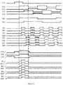
- FIG. 9 is a driving time sequence diagram of a gate driving circuit in a first resolution mode provided by an embodiment of the present disclosure
- FIG. 10 is a driving time sequence diagram of the gate driving circuit in a second resolution mode provided by an embodiment of the present disclosure
- FIG. 11 is a driving time sequence diagram of the gate driving circuit in a third resolution mode provided by an embodiment of the present disclosure.
- a resolution of the first resolution mode is 8K
- a resolution of the second resolution mode is UD (4K)
- a resolution of the third resolution mode is FDH (2K). That is to say, the resolution of the first resolution mode is twice of the resolution of the second resolution mode, and the resolution of the second resolution mode is twice of the resolution of the third resolution mode.
- the shift-buffer circuit and the gate driving circuit provided by the embodiments of the present disclosure may achieve four times of the resolution change in different regions.
- a first trigger signal STV with a high level is input to a first electrode and a gate electrode of the first shift transistor T1, and the first shift transistor T1 inputs the first trigger signal STV with the high level to a shift pull-up node SPU_1, the third shift transistor T3 is turned on, the sixth shift transistor T6 is turned on, a low level voltage of the first power supply terminal VGL1 is input to the first shift pull-down node SPD1, the second shift transistor T2 and the fourth shift transistor T4 are turned off, and since the second shift pull-down node SPD2 is at a low level, the seventh shift transistor T7 and the eighth shift transistor T8 are turned off; a shift clock signal CLKS with a high level is input to a shift output terminal SOUT_1 through the third shift transistor T3; due to a bootstrap effect of a shift storage capacitor SC, a voltage of the shift pull-up node SPU_1 is further increased, so that the third shift transistor
- the shift output terminal SOUT_1 inputs a high level voltage to a buffer input terminal BIN, a first enabled signal EN1 with a high level is input to a gate electrode of the first buffer transistor M1 through an enabled signal terminal EN, the first buffer transistor M1 is turned on, and the first buffer transistor M1 inputs a high level voltage of the buffer input terminal BIN to the buffer pull-up node BPU; since the first buffer pull-down node BPD1 is connected with the first shift pull-down node SPD1, the first buffer pull-down node BPD1 is also at a low level, the second buffer transistor M2 and the fourth buffer transistor M4 are turned off, and since the second buffer pull-down node BPD2 is at a low level, the fifth buffer transistor M5 and the sixth buffer transistor M6 are turned off; and a buffer clock signal CLKB with a high level is input to a buffer output terminal BOUT_1 through the third buffer transistor M3; Due to the bootstrap effect of the buffer storage capacitor BC, a voltage of a buffer pull-up no
- buffer clock signals for example, from the first buffer clock CB1, the second buffer clock CB2, the third buffer clock CB3 and the fourth buffer clock CB4, are sequentially applied to the four buffers connected with the same shift register, respectively, so that the buffers may output the buffer output signals sequentially.
- buffer clock signals for example, from the first buffer clock CB1, the second buffer clock CB2, the third buffer clock CB3 and the fourth buffer clock CB4, are sequentially applied to the four buffers connected with the shift register of the odd-numbered stage, respectively; during a period when a shift register of an even-numbered stage (2n-th stage, where n is an integer greater than 0) has a shift output signal with a high level, buffer clock signals, for example, from the fifth buffer clock CB5, the sixth buffer clock CB6, the seventh buffer clock CB7, and the eighth buffer clock CB8, are sequentially applied to the four buffers connected with the shift register of the even-numbered stage respectively, so that the buffers may output the buffer output signals sequentially. In this way, the first resolution mode is realized.
- a difference between FIG. 10 and FIG. 9 includes, by adjusting time sequences of the first buffer clock CB1, the second buffer clock CB2, the third buffer clock CB3, the fourth buffer clock CB4, the buffer clock CB5, the sixth buffer clock CB6, the seventh buffer clock CB7 and the eighth buffer clock CB8, to make the first buffer clock CB1 and the second buffer clock CB2 have a same time sequence, the third buffer clock CB3 and the fourth buffer clock CB4 have a same time sequence, the fifth buffer clock CB5 and the sixth buffer clock CB6 have a same time sequence, and the seventh buffer clock CB7 and the eighth buffer clock CB8 have a same time sequence.
- two adjacent buffers have a same output, so that every two adjacent gate lines in a corresponding display panel may be turned on simultaneously to receive a same data signal.
- resolution in the case of FIG. 10 is reduced to half of that of the case in FIG. 9 , that is, a frame frequency of the case in FIG. 10 may be increased by two times compared with that of the case in FIG. 9 . In this way, the second resolution mode is realized.
- a difference between FIG. 11 and FIG. 9 includes making the first buffer clock CB1, the second buffer clock CB2, the third buffer clock CB3 and the fourth buffer clock CB4 have a same time sequence, and also making the fifth buffer clock CB5, the sixth buffer clock CB6, the seventh buffer clock CB7 and the eighth buffer clock CB8 have a same time sequence, by adjusting time sequences of the first buffer clock CB1, the second buffer clock CB2, the third buffer clock CB3, the fourth buffer clock CB4, the buffer clock CB5, the sixth buffer clock CB6, the seventh buffer clock CB7 and the eighth buffer clock CB8.
- four adjacent buffers have a same output.
- every four adjacent gate lines in the corresponding display panel may be turned on simultaneously to receive the same data signal.
- resolution in the case of FIG. 11 is reduced to one quarter of that of the case in FIG. 9 , that is, a frame frequency of the case in FIG. 11 may be increased by four times compared with that of the case in FIG. 9 . In this way, the third resolution mode is realized.
- the gate driving circuit or the display panel may be divided into a plurality of different row blocks.
- the first resolution mode may be applied in some row blocks to realize high resolution (e.g., 8K) display
- the second resolution mode is applied in some row blocks to realize medium resolution (e.g., UD, 4K) display, thereby taking into account both the resolution and the frame frequency.
- the third resolution mode is applied in some row blocks to realize low resolution (e.g., FHD, 2K) display, thereby increasing the frame frequency.
- an underscore and a number following the underscore (e.g., "_1") in the above description denote a shift register of a corresponding stage, a buffer of a corresponding stage or a component thereof.
- “SPU_1” denotes the first shift pull-up node of the shift register of the first stage
- “SOUT_1” denotes the shift output terminal of the shift register of the first stage
- “SPD1_1” denotes the first shift pull-down node of the shift register of the first stage.
- BOUT_1 denotes the buffer output terminal of the first buffer
- BOUT_2 denotes the buffer output terminal of the second buffer
- BOUT_3 denotes the buffer output terminal of the third buffer
- BOUT_4" denotes the buffer output terminal of the fourth buffer.
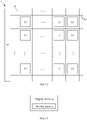
- An embodiment of the present disclosure further provides a display panel 1, as shown in FIG. 12 , the display panel 1 comprises the gate driving circuit 10 provided by any embodiment of the present disclosure.
- the display panel 1 provided by an embodiment of the present disclosure further comprises gate lines 11, data lines 12, and a plurality of pixel units 13 defined by intersecting the gate lines 11 and the data lines 12, and the gate driving circuit 10 is configured to provide gate driving signals to the gate lines.
- the gate lines 11 may include the gate lines G1, G2 ... G4m shown in FIG. 8 , each buffer from the buffers BF1, BF2 ... BF4m is used for outputting a gate driving signal to a corresponding gate line G1, G2 ... G4m.
- an embodiment of the present disclosure further provides a display device 2, as shown in FIG. 13 , and the display device 2 comprises the display panel 1 provided by any embodiment of the present disclosure.
- the display device 2 may be any product or component having a display function such as an electronic paper, a cell phone, a tablet computer, a television, a monitor, a notebook computer, a digital photo frame, a navigator and so on.
- a display function such as an electronic paper, a cell phone, a tablet computer, a television, a monitor, a notebook computer, a digital photo frame, a navigator and so on.
- the display device 2 may further comprise a signal receiving circuit, a video signal decoding circuit and the like, so as to receive and process the video signal, or may further comprise a modulation and demodulation circuit or an antenna and the like, so as to have signal connection with other equipment through network, wireless signal and the like.
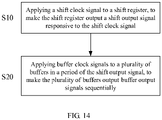
- An embodiment of the present disclosure further provides a method of driving the shift-buffer circuit 100 provided by any embodiment of the present disclosure, and as shown in FIG. 14 , the method comprises the following steps:
- step S10 a shift clock signal CLKS with a high level is applied to the shift register 110, so that the shift register 110 outputs the shift output signal in response to the shift clock signal CLKS with the high level.
- a buffer clock signal CLKB with a high level is applied to the plurality of buffers 120 in a period of the high-level shift output signal, so that the plurality of buffers 120 output the buffer output signals each with a high level sequentially.
- the shift-buffer circuit, the gate driving circuit, the display panel and the driving method provided by the embodiments of the present disclosure may change the display resolution and may perform selective driving in different regions of the display panel.
Landscapes
- Engineering & Computer Science (AREA)
- Physics & Mathematics (AREA)
- Computer Hardware Design (AREA)
- General Physics & Mathematics (AREA)
- Theoretical Computer Science (AREA)
- Microelectronics & Electronic Packaging (AREA)
- Power Engineering (AREA)
- Chemical & Material Sciences (AREA)
- Crystallography & Structural Chemistry (AREA)
- Liquid Crystal Display Device Control (AREA)
- Shift Register Type Memory (AREA)
- Control Of Indicators Other Than Cathode Ray Tubes (AREA)
Claims (10)
- Schiebepufferschaltung (100), umfassend ein Schieberegister (110) und eine Mehrzahl von mit dem Schieberegister (110) verbundenen Puffern (120), wobei:das Schieberegister (110) einen Ausgabeanschluss (SOUT) beinhaltet;das Schieberegister (110) konfiguriert ist, ein Schiebeausgabesignal von dem Schiebeausgabeanschluss (SOUT) auszugeben, in Antwort auf ein Schiebetaktsignal;jeder der Puffer (120) einen Puffereingabeanschluss (BIN) und einen Pufferausgabeanschluss (BOUT) beinhaltet, wobei der Puffereingabeanschluss (BIN) mit dem Schiebeausgabeanschluss (SOUT) verbunden ist;jeder der Puffer (120) konfiguriert ist, ein Pufferausgabesignal von dem Pufferausgabeanschluss (BOUT) in Antwort auf ein Puffertaktsignal auszugeben;wobei die Schieberegister (110) beinhalten:eine Schiebeeingabeschaltung (111), jeweils verbunden mit einem Schiebeeingabeanschluss (SIN) und einem Schiebe-Pull-Up-Knoten (SPU);eine erste Schieberückstellschaltung (112), jeweils verbunden mit dem Schiebe-Pull-Up-Knoten (SPU), einem ersten Schiebe-Pull-Down-Knoten (SPD1) und einem ersten Energiezufuhranschluss (VGL1);eine Schiebeausgabeschaltung (113), jeweils verbunden mit dem Schiebe-Pull-Up-Knoten (SPU), einem Schiebetaktsignalanschluss und dem Schiebeausgabeanschluss (SOUT);eine erste Schiebeausgabe-Pull-Down-Schaltung (114), jeweils verbunden mit dem Schiebeausgabeanschluss (SOUT), dem ersten Schiebe-Pull-Down-Knoten (SPD1) und dem ersten Energiezufuhranschluss (VGL1);eine erste Pull-Down-Knotensteuerschaltung (115), jeweils verbunden mit dem ersten Schiebe-Pull-Down-Knoten (SPD1), einem ersten Energiesignalanschluss (VDD1) und dem ersten Energiezufuhranschluss (VGL1); undeinen Schiebespeicherkondensator (SC), jeweils verbunden mit dem Schiebe-Pull-Up-Knoten (SPU) und dem Schiebeausgabeanschluss (SOUT);wobei die Schiebeeingabeschaltung (111) einen ersten Schiebetransistor (T1) beinhaltet; wobei eine erste Elektrode von dem ersten Schiebetransistor (T1) mit dem Schiebeeingabeanschluss (SIN) verbunden ist, wobei eine Gate-Elektrode von dem ersten Schieberegister (T1) mit dem Schiebeeingabeanschluss (SIN) verbunden ist, und wobei eine zweite Elektrode von dem ersten Schiebetransistor (T1) mit dem Schiebe-Pull-Up-Knoten (SPU) verbunden ist;wobei die erste Schieberückstellschaltung (112) einen zweiten Schiebetransistor (T2) beinhaltet, wobei eine erste Elektrode von dem zweiten Schiebetransistor (T2) mit dem Schiebe-Pull-Up-Knoten (SPU) verbunden ist, wobei eine Gate-Elektrode von dem zweiten Schiebetransistor (T2) mit dem ersten Schiebe-Pull-Down-Knoten (SPD1) verbunden ist, und wobei eine zweite Elektrode von dem zweiten Schiebetransistor (T2) mit dem ersten Energiezufuhranschluss (VGL1) verbunden ist;wobei die Schiebeausgabeschaltung (113) einen dritten Schiebetransistor (T3) beinhaltet, wobei eine erste Elektrode von dem dritten Schiebetransistor (T3) mit dem Schiebetaktsignalanschluss verbunden ist, wobei eine Gate-Elektrode von dem dritten Schiebetransistor (T3) mit dem Schiebe-Pull-Up-Knoten (SPU) verbunden ist, und wobei eine zweite Elektrode von dem dritten Schiebetransistor (T3) mit dem Schiebeausgabeanschluss (SOUT) verbunden ist;wobei die erste Schiebeausgabe-Pull-Down-Schaltung (114) einen vierten Schiebetransistor (T4) beinhaltet, wobei eine erste Elektrode von dem vierten Schiebetransistor (T4) mit dem Schiebeausgabeanschluss (SOUT) verbunden ist, wobei eine Gate-Elektrode von dem vierten Schiebetransistor (T4) mit dem Schiebe-Pull-Down-Knoten (SPD1) verbunden ist, und wobei eine zweite Elektrode von dem vierten Schiebetransistor (T4) mit dem ersten Energiezufuhranschluss (VGL1) verbunden ist;wobei die erste Pull-Down-Knotensteuerschaltung (115) einen fünften Schiebetransistor (T5) und einen sechsten Schiebetransistor (T6) beinhaltet, wobei eine erste Elektrode von dem fünften Schiebetransistor (T5) mit dem ersten Energiesignalanschluss (VDD1) verbunden ist, wobei eine Gate-Elektrode von dem fünften Transistor (T5) mit dem ersten Energiesignalanschluss (VDD1) verbunden ist, wobei eine zweite Elektrode von dem fünften Schiebetransistor (T5) mit dem ersten Schiebe-Pull-Down-Knoten (SPD1) verbunden ist, wobei eine erste Elektrode von dem sechsten Schiebetransistor (T6) mit dem ersten Schiebe-Pull-Down-Knoten (SPD1) verbunden ist, wobei eine Gate-Elektrode von dem sechsten Schiebetransistor (T6) mit dem Schiebe-Pull-Up-Knoten (SPU) verbunden ist, und wobei eine zweite Elektrode von dem sechsten Schiebetransistor (T6) mit dem ersten Energiezufuhranschluss (VGL1) verbunden ist; undwobei ein erster Anschluss von dem Schiebespeicherkondensator (SC) mit dem Schiebe-Pull-Up-Knoten (SPU) verbunden ist, und wobei ein zweiter Anschluss von dem Schiebespeicherkondensator (SC) mit dem Schiebeausgabeanschluss (SOUT) verbunden ist;wobei jeder der Speicher (120) außerdem beinhaltet:eine Puffereingabeschaltung (121), die jeweils mit dem Puffereingabeanschluss (BIN) und einem Puffer-Pull-Up-Knoten (BPU) verbunden ist;eine erste Pufferrückstellschaltung (122), die jeweils mit dem Puffer-Pull-Up-Knoten (BPU), einem ersten Puffer-Pull-Down-Knoten (BPD1) und einem zweiten Energiezufuhranschluss (VGL2) verbunden ist;eine Pufferausgabeschaltung (123), die jeweils mit dem Puffer-Pull-Up-Knoten (BPU), einem Puffertaktsignalanschluss und dem Pufferausgabeanschluss (BOUT) verbunden ist;eine erste Pufferausgabe-Pull-Down-Schaltung (124), die jeweils mit dem Pufferausgabeanschluss (BOUT), dem ersten Puffer-Pull-Down-Knoten (BPD1) und dem zweiten Energiezufuhranschluss (VGL2) verbunden ist;einen Pufferspeicherkondensator (SC), der jeweils mit dem Puffer-Pull-Up-Knoten (BPU) und dem Pufferausgabeanschluss (BOUT) verbunden ist;wobei die Puffereingabeschaltung (121) einen ersten Puffertransistor (M1) beinhaltet, wobei eine erste Elektrode von dem ersten Puffertransistor (M1) mit dem Puffereingabeanschluss (BIN) verbunden ist, wobei eine Gate-Elektrode von dem ersten Puffertransistor (M1) mit einem Freigabesignalanschluss verbunden ist, und wobei eine zweite Elektrode von dem ersten Puffertransistor (M1) mit dem Puffer-Pull-Up-Knoten (BPU) verbunden ist;wobei die erste Pufferrückstellschaltung (122) einen zweiten Puffertransistor (M2) beinhaltet, wobei eine erste Elektrode von dem zweiten Puffertransistor (M2) mit dem Puffer-Pull-Up-Knoten (BPU) verbunden ist, wobei eine Gate-Elektrode von dem zweiten Puffertransistor (M2) mit dem ersten Puffer-Pull-Down-Knoten (BPD1) verbunden ist, und wobei eine zweite Elektrode von dem zweiten Puffertransistor (M2) mit dem zweiten Energiezufuhranschluss (VGL2) verbunden ist;wobei die Pufferausgabeschaltung (123) einen dritten Puffertransistor (M3) beinhaltet, wobei eine erste Elektrode von dem dritten Puffertransistor (M3) mit dem Puffertaktsignalanschluss verbunden ist, wobei eine Gate-Elektrode von dem dritten Puffertransistor (M3) mit dem Puffer-Pull-Up-Knoten (BPU) verbunden ist, und wobei eine zweite Elektrode von dem dritten Puffertransistor (M3) mit dem Pufferausgabeanschluss (BOUT) verbunden ist;wobei die Pufferausgabe-Pull-Down-Schaltung (124) einen vierten Puffertransistor (M4) beinhaltet, wobei eine erste Elektrode von dem vierten Puffertransistor (M4) mit dem Pufferausgabeanschluss (BOUT) verbunden ist, wobei eine Gate-Elektrode von dem vierten Puffertransistor (M4) mit dem ersten Puffer-Pull-Down-Knoten (BPD1) verbunden ist, und wobei eine zweite Elektrode von dem vierten Puffertransistor (M4) mit dem zweiten Energiezufuhranschluss (VGL2) verbunden ist; undwobei ein erster Anschluss von dem Pufferspeicherkondensator (BC) mit dem Puffer-Pull-Up-Knoten (BPU) verbunden ist, und wobei ein zweiter Anschluss von dem Pufferspeicherkondensator (BC) mit dem Pufferausgabeanschluss (BOUT) verbunden ist;wobei das Schieberegister (110) außerdem beinhaltet:eine zweite Schieberückstellschaltung (116), die jeweils mit dem Schiebe-Pull-Up-Knoten (SPU), einem zweiten Schiebe-Pull-Down-Knoten (SPD2) und dem ersten Energiezufuhranschluss (VGL1) verbunden ist;eine zweite Schiebeausgabe-Pull-Down-Schaltung (117), die jeweils mit dem Schiebeausgabeanschluss (SOUT), dem zweiten Schiebe-Pull-Down-Knoten (SPD2) und dem ersten Energiezufuhranschluss (VGL1) verbunden ist; undeine zweite Pull-Down-Knotensteuerschaltung (118), die jeweils mit dem zweiten Schiebe-Pull-Down-Knoten (SPD2), einem zweiten Energiesignalanschluss (VDD2) und dem ersten Energiezufuhranschluss (VGL1) verbunden ist,wobei ein mittels des ersten Energiesignalanschlusses (VDD1) bereitgestelltes erstes Energiesignal und ein mittels des zweiten Energiesignalanschlusses (VDD2) bereitgestelltes zweites Energiesignal gegenseitig umgekehrte Signale sind;wobeijeder der Puffer (120) außerdem beinhaltet:eine zweite Pufferrückstellschaltung (125), die jeweils mit dem Puffer-Pull-Up-Knoten (BPU), einem zweiten Puffer-Pull-Down-Knoten (BPD2) und dem zweiten Energiezufuhranschluss (VGL2) verbunden ist; undeine zweite Pufferausgabe-Pull-Down-Schaltung (126), die jeweils mit dem Pufferausgabeanschluss (BOUT), dem zweiten Puffer-Pull-Down-Knoten (BPD2) und dem zweiten Energiezufuhranschluss (VGL2) verbunden ist,wobei der erste Puffer-Pull-Down-Knoten (BPD1) mit dem ersten Schiebe-Pull-Down-Knoten (SPD1) verbunden ist, und wobei der zweite Puffer-Pull-Down-Knoten (BPD2) mit dem zweiten Schiebe-Pull-Down-Knoten (SPD2) verbunden ist.
- Schiebepufferschaltung (100) gemäß Anspruch 1, wobei der zweite Energiezufuhranschluss (VGL2) mit dem ersten Energiezufuhranschluss (VGL1) verbunden ist.
- Schiebepufferschaltung (100) gemäß Anspruch 1, wobei:die zweite Schieberückstellschaltung (116) einen siebten Schiebetransistor (T7) beinhaltet, wobei eine erste Elektrode von dem siebten Schiebetransistor (T7) mit dem Schiebe-Pull-Up-Knoten (SPU) verbunden ist, wobei eine Gate-Elektrode von dem siebten Schiebetransistor (T7) mit dem zweiten Schiebe-Pull-Down-Knoten verbunden ist, und wobei eine zweite Elektrode von dem siebten Schiebetransistor (T7) mit dem ersten Energiezufuhranschluss (VGL1) verbunden ist;eine zweite Schiebeausgabe-Pull-Down-Schaltung (117) eine achten Schiebetransistor (T8) beinhaltet, wobei eine erste Elektrode von dem achten Schiebetransistor (T8) mit dem Schiebeausgabeanschluss (SOUT) verbunden ist, eine Gate-Elektrode von dem achten Schiebetransistor (T8) mit dem zweiten Schiebe-Pull-Down-Knoten (SPD2) verbunden ist, und eine zweite Elektrode von dem achten Schiebetransistor (T8) mit dem ersten Energiezufuhranschluss (VGL1) verbunden ist;die zweite Pull-Down-Knotensteuerschaltung (118) einen neunten Schiebetransistor (T9) und einen zehnten Schiebetransistor (T10) beinhaltet, wobei eine erste Elektrode von dem neunten Schiebetransistor (T9) mit dem zweiten Energiesignalanschluss (VDD2) verbunden ist, wobei eine Gate-Elektrode von dem neunten Schiebetransistor (T9) mit dem zweiten Energiesignalanschluss (VDD2) verbunden ist, wobei eine zweite Elektrode von dem neunten Schiebetransistor (T9) mit dem zweiten Schiebe-Pull-Down-Knoten (SPD2) verbunden ist, wobei eine erste Elektrode von dem zehnten Schiebetransistor (T10) mit dem zweiten Schiebe-Pull-Down-Knoten (SPD2) verbunden ist, wobei eine Gate-Elektrode von dem zehnten Schiebetransistor (T10) mit dem Schiebe-Pull-Up-Knoten (SPU) verbunden ist, und wobei eine zweite Elektrode von dem zehnten Schiebetransistor (T10) mit dem ersten Energiezufuhranschluss (VGL1) verbunden ist;die zweite Pufferrückstellschaltung (125) einen fünften Puffertransistor (M5) beinhaltet, wobei eine erste Elektrode von dem fünften Puffertransistor (M5) mit dem Puffer-Pull-Up-Knoten (BPU) verbunden ist, wobei eine Gate-Elektrode von dem fünften Puffertransistor (M5) mit dem zweiten Puffer-Pull-Down-Knoten (BPD2) verbunden ist, und wobei eine zweite Elektrode von dem fünften Puffertransistor (M5) mit dem zweiten Energiezufuhranschluss (VGL2) verbunden ist; und wobeidie zweite Pufferausgabe-Pull-Down-Schaltung (126) einen sechsten Puffertransistor (M6) beinhaltet, wobei eine erste Elektrode von dem sechsten Puffertransistor (M6) mit dem Pufferausgabeanschluss (BOUT) verbunden ist, wobei eine Gate-Elektrode von dem sechsten Puffertransistor (M6) mit dem zweiten Puffer-Pull-Down-Knoten (BPD2) verbunden ist, und wobei eine zweite Elektrode von dem sechsten Puffertransistor (M6) mit dem zweiten Energiezufuhranschluss (VGL2) verbunden ist.
- Schiebepufferschaltung (100) gemäß einem der Ansprüche 1 - 3, wobei jedes der Schieberegister (110) mit vier von den Puffern (120) verbunden ist.
- Gate-Treiberschaltung, umfassend Schiebepufferschaltungen (100) in einer Mehrzahl von Stufen, wobei eine Schiebepufferschaltung (100) von jeder Stufe die Schiebepufferschaltung (100) gemäß einem der Ansprüche 1 bis 4 beinhaltet.
- Gate-Treiberschaltung gemäß Anspruch 5, wobei:ein Schiebeausgabeanschluss (SOUT) von einem Schieberegister (110) in einer Schiebepufferschaltung (100) von einer (2n-1)-ten Stufe verbunden ist mit einem Schiebeeingabeanschluss (SIN) von einem Schieberegister (110) in einer Schiebepufferschaltung (100) von einer (2n+1)-ten Stufe; undein Schiebeausgabeanschluss (SOUT) von einem Schieberegister (110) in einer Schiebepufferschaltung (100) von einer 2n-ten Stufe verbunden ist mit einem Schiebeeingabeanschluss (SIN) von einem Schieberegister (110) in einer Schiebepufferschaltung (100) von einer (2n+2)-ten Stufe,wobei n eine Integerzahl größer als null ist.
- Gate-Treiberschaltung gemäß Anspruch 6, wobeiein Freigabesignalanschluss von einem Puffer (120) in der Schiebepufferschaltung (100) von der (2n-1)-ten Stufe konfiguriert ist, um ein erstes Freigabesignal zu empfangen; undwobei ein Freigabesignalanschluss von einem Puffer (120) in der Schiebepufferschaltung (100) von der 2n-ten Stufe konfiguriert ist, um ein zweites Freigabesignal zu empfangen.
- Anzeigepanel, umfassend die Gate-Treiberschaltung gemäß einem der Ansprüche 5 bis 7.
- Anzeigevorrichtung, umfassend das Anzeigepanel gemäß Anspruch 8.
- Verfahren zur Ansteuerung der Schiebepufferschaltung (100) gemäß einem der Ansprüche 1 bis 4, umfassend:Zuführen eines Schiebetaktsignals zu einem Schieberegister (110), um das Schieberegister (110) zu veranlassen, ein Schiebeausgabesignal in Antwort auf das Schiebetaktsignal auszugeben; undZuführen von Puffertaktsignalen an eine Mehrzahl von Puffern (120) in einer Periode von dem Schiebeausgabesignal, um die Mehrzahl von Puffern (120) zu veranlassen, sequenziell Pufferausgabesignale auszugeben.
Applications Claiming Priority (2)
| Application Number | Priority Date | Filing Date | Title |
|---|---|---|---|
| CN201710218273.7A CN108694894B (zh) | 2017-04-05 | 2017-04-05 | 移位缓存及栅极驱动电路、显示面板及设备和驱动方法 |
| PCT/CN2017/106517 WO2018184372A1 (zh) | 2017-04-05 | 2017-10-17 | 移位缓存电路、栅极驱动电路、显示面板、显示设备和驱动方法 |
Publications (3)
| Publication Number | Publication Date |
|---|---|
| EP3608901A1 EP3608901A1 (de) | 2020-02-12 |
| EP3608901A4 EP3608901A4 (de) | 2020-12-02 |
| EP3608901B1 true EP3608901B1 (de) | 2022-04-20 |
Family
ID=63711956
Family Applications (1)
| Application Number | Title | Priority Date | Filing Date |
|---|---|---|---|
| EP17861186.9A Active EP3608901B1 (de) | 2017-04-05 | 2017-10-17 | Verschiebungspufferschaltung, gate-treiberschaltung, anzeigetafel, anzeigevorrichtung und ansteuerungsverfahren |
Country Status (4)
| Country | Link |
|---|---|
| US (1) | US10540938B2 (de) |
| EP (1) | EP3608901B1 (de) |
| CN (1) | CN108694894B (de) |
| WO (1) | WO2018184372A1 (de) |
Families Citing this family (17)
| Publication number | Priority date | Publication date | Assignee | Title |
|---|---|---|---|---|
| CN108346402B (zh) * | 2017-01-22 | 2019-12-24 | 京东方科技集团股份有限公司 | 一种栅极驱动电路及其驱动方法、显示装置 |
| CN106782284B (zh) * | 2017-03-02 | 2018-02-27 | 京东方科技集团股份有限公司 | 移位寄存器及其驱动方法、栅极驱动装置以及显示装置 |
| CN108122529B (zh) * | 2018-01-25 | 2021-08-17 | 京东方科技集团股份有限公司 | 栅极驱动单元及其驱动方法和栅极驱动电路 |
| CN108172192B (zh) * | 2018-03-20 | 2020-11-03 | 京东方科技集团股份有限公司 | 移位寄存器单元、驱动方法、栅极驱动电路和显示设备 |
| CN108447438B (zh) * | 2018-04-10 | 2020-12-08 | 京东方科技集团股份有限公司 | 显示装置、栅极驱动电路、移位寄存器及其控制方法 |
| CN108597437B (zh) * | 2018-06-20 | 2021-08-27 | 京东方科技集团股份有限公司 | 一种移位寄存器、栅极驱动电路及其驱动方法、显示装置 |
| CN109767740B (zh) * | 2019-03-25 | 2021-01-22 | 京东方科技集团股份有限公司 | 移位寄存器、栅极驱动电路及其驱动方法、显示装置 |
| CN110503921B (zh) * | 2019-09-18 | 2020-11-10 | 京东方科技集团股份有限公司 | 栅极驱动电路及其驱动方法、显示装置 |
| WO2022252053A1 (zh) * | 2021-05-31 | 2022-12-08 | 京东方科技集团股份有限公司 | 行驱动信号增强电路、移位寄存器单元和显示面板 |
| KR102812891B1 (ko) * | 2021-11-30 | 2025-05-23 | 엘지디스플레이 주식회사 | 게이트 드라이버를 갖는 디스플레이 장치 |
| KR20230103704A (ko) * | 2021-12-31 | 2023-07-07 | 엘지디스플레이 주식회사 | 발광표시장치 |
| US20250131885A1 (en) * | 2023-10-24 | 2025-04-24 | Apple Inc. | Display with Silicon Gate Drivers and Semiconducting Oxide Pixels |
| WO2024130493A1 (zh) * | 2022-12-19 | 2024-06-27 | 京东方科技集团股份有限公司 | 驱动电路、驱动方法、驱动模组和显示装置 |
| US12354558B2 (en) | 2022-12-19 | 2025-07-08 | Chengdu Boe Optoelectronics Technology Co., Ltd. | Driving circuit, driving method, driving module and display device |
| WO2024130491A1 (zh) | 2022-12-19 | 2024-06-27 | 京东方科技集团股份有限公司 | 驱动电路、驱动方法、驱动模组和显示装置 |
| WO2024130492A1 (zh) | 2022-12-19 | 2024-06-27 | 京东方科技集团股份有限公司 | 驱动电路、驱动方法、驱动模组和显示装置 |
| GB2638079A (en) | 2022-12-19 | 2025-08-13 | Boe Technology Group Co Ltd | Driving circuit, driving method, driving module, and display device |
Family Cites Families (19)
| Publication number | Priority date | Publication date | Assignee | Title |
|---|---|---|---|---|
| TWI386904B (zh) * | 2008-05-12 | 2013-02-21 | Chimei Innolux Corp | 平面顯示器 |
| CN101847445B (zh) * | 2009-03-27 | 2012-11-21 | 北京京东方光电科技有限公司 | 移位寄存器及其栅线驱动装置 |
| TWI407400B (zh) * | 2009-09-14 | 2013-09-01 | Au Optronics Corp | 液晶顯示器、平面顯示器及其閘極驅動方法 |
| US8325127B2 (en) * | 2010-06-25 | 2012-12-04 | Au Optronics Corporation | Shift register and architecture of same on a display panel |
| US9330782B2 (en) * | 2010-07-13 | 2016-05-03 | Sharp Kabushiki Kaisha | Shift register and display device having the same |
| TWI431585B (zh) * | 2010-11-30 | 2014-03-21 | Au Optronics Corp | 多工式驅動電路 |
| JP5963551B2 (ja) * | 2012-06-06 | 2016-08-03 | キヤノン株式会社 | アクティブマトリクスパネル、検出装置、及び、検出システム |
| CN103578433B (zh) * | 2012-07-24 | 2015-10-07 | 北京京东方光电科技有限公司 | 一种栅极驱动电路、方法及液晶显示器 |
| TWI552129B (zh) * | 2014-11-26 | 2016-10-01 | 群創光電股份有限公司 | 掃描驅動電路及應用其之顯示面板 |
| CN104732939A (zh) * | 2015-03-27 | 2015-06-24 | 京东方科技集团股份有限公司 | 移位寄存器、栅极驱动电路、显示装置及栅极驱动方法 |
| CN104835476B (zh) * | 2015-06-08 | 2017-09-15 | 京东方科技集团股份有限公司 | 移位寄存器单元、栅极驱动电路及其驱动方法、阵列基板 |
| CN104867439B (zh) * | 2015-06-24 | 2017-04-05 | 合肥京东方光电科技有限公司 | 移位寄存器单元及其驱动方法、栅极驱动电路及显示装置 |
| US9626895B2 (en) * | 2015-08-25 | 2017-04-18 | Chunghwa Picture Tubes, Ltd. | Gate driving circuit |
| CN105304044B (zh) * | 2015-11-16 | 2017-11-17 | 深圳市华星光电技术有限公司 | 液晶显示设备及goa电路 |
| CN105788555B (zh) * | 2016-05-19 | 2018-04-10 | 京东方科技集团股份有限公司 | 移位寄存器单元及其驱动方法、栅极驱动电路、显示装置 |
| CN105869566B (zh) * | 2016-06-21 | 2019-12-03 | 京东方科技集团股份有限公司 | 移位寄存器单元、驱动方法、栅极驱动电路及显示装置 |
| CN105895046B (zh) * | 2016-06-22 | 2018-12-28 | 京东方科技集团股份有限公司 | 移位寄存器、栅极驱动电路以及显示设备 |
| CN106157898B (zh) * | 2016-06-28 | 2019-05-03 | 厦门天马微电子有限公司 | 一种扫描电路、栅极驱动电路及显示装置 |
| CN106710508B (zh) * | 2017-02-17 | 2020-07-10 | 京东方科技集团股份有限公司 | 移位寄存器、栅线驱动方法、阵列基板和显示装置 |
-
2017
- 2017-04-05 CN CN201710218273.7A patent/CN108694894B/zh not_active Expired - Fee Related
- 2017-10-17 US US15/768,948 patent/US10540938B2/en active Active
- 2017-10-17 WO PCT/CN2017/106517 patent/WO2018184372A1/zh not_active Ceased
- 2017-10-17 EP EP17861186.9A patent/EP3608901B1/de active Active
Also Published As
| Publication number | Publication date |
|---|---|
| EP3608901A1 (de) | 2020-02-12 |
| CN108694894B (zh) | 2020-07-07 |
| US10540938B2 (en) | 2020-01-21 |
| EP3608901A4 (de) | 2020-12-02 |
| WO2018184372A1 (zh) | 2018-10-11 |
| US20190057638A1 (en) | 2019-02-21 |
| CN108694894A (zh) | 2018-10-23 |
Similar Documents
| Publication | Publication Date | Title |
|---|---|---|
| EP3608901B1 (de) | Verschiebungspufferschaltung, gate-treiberschaltung, anzeigetafel, anzeigevorrichtung und ansteuerungsverfahren | |
| US10789868B2 (en) | Shift register circuit and method for driving the same, gate driving circuit and method for driving the same, and display apparatus | |
| CN109285496B (zh) | 移位寄存器单元、栅极驱动电路及其驱动方法、显示装置 | |
| EP3254277B1 (de) | Schieberegistereinheit, zugehöriger gate-treiber und anzeigevorrichtung sowie verfahren zur ansteuerung davon | |
| KR101521706B1 (ko) | 게이트 구동 회로, 어레이 기판 및 디스플레이 장치 | |
| US9129576B2 (en) | Gate driving waveform control | |
| CN104821159B (zh) | 一种栅极驱动电路、显示面板及触控显示装置 | |
| US9530521B2 (en) | Shift register unit, gate driving circuit, and display device | |
| US10657879B1 (en) | Gate driving circuit, method for driving the same, and display apparatus | |
| US20170178582A1 (en) | Shift register, gate driving circuit, display panel, driving method thereof and display device | |
| US11783743B2 (en) | Shifting register, driving method thereof, driving circuit and display device | |
| US9881542B2 (en) | Gate driver on array (GOA) circuit cell, driver circuit and display panel | |
| WO2017067300A1 (zh) | 一种栅极驱动电路及其驱动方法、显示面板 | |
| WO2017219658A1 (zh) | 移位寄存器、栅极驱动电路以及显示设备 | |
| CN105654991B (zh) | 移位寄存器及其驱动方法、goa电路以及显示装置 | |
| EP3882901B1 (de) | Schieberegistereinheit und antriebsverfahren, gate-treiberschaltung und anzeigevorrichtung | |
| CN101504829B (zh) | 具有双向稳压功能的液晶显示装置及移位寄存器 | |
| WO2016206240A1 (zh) | 移位寄存器单元及其驱动方法、移位寄存器和显示装置 | |
| CN107068033B (zh) | 移位寄存器单元、栅极驱动电路、测试方法及显示装置 | |
| US11100841B2 (en) | Shift register, driving method thereof, gate driving circuit, and display device | |
| US20140043304A1 (en) | Shift registers, display panels, display devices, and electronic devices | |
| US12198772B2 (en) | Shift register and driving method thereof, gate driving circuit, and display device | |
| US20170103722A1 (en) | Shift register unit, gate driving circuit and display apparatus | |
| EP3678138A1 (de) | Schieberegister, gatetreiberschaltung, anzeigetafel und antriebsverfahren | |
| US11183103B2 (en) | Shift register unit and driving method thereof, gate driving circuit, and display device |
Legal Events
| Date | Code | Title | Description |
|---|---|---|---|
| STAA | Information on the status of an ep patent application or granted ep patent |
Free format text: STATUS: UNKNOWN |
|
| STAA | Information on the status of an ep patent application or granted ep patent |
Free format text: STATUS: THE INTERNATIONAL PUBLICATION HAS BEEN MADE |
|
| PUAI | Public reference made under article 153(3) epc to a published international application that has entered the european phase |
Free format text: ORIGINAL CODE: 0009012 |
|
| STAA | Information on the status of an ep patent application or granted ep patent |
Free format text: STATUS: REQUEST FOR EXAMINATION WAS MADE |
|
| 17P | Request for examination filed |
Effective date: 20180424 |
|
| AK | Designated contracting states |
Kind code of ref document: A1 Designated state(s): AL AT BE BG CH CY CZ DE DK EE ES FI FR GB GR HR HU IE IS IT LI LT LU LV MC MK MT NL NO PL PT RO RS SE SI SK SM TR |
|
| AX | Request for extension of the european patent |
Extension state: BA ME |
|
| DAV | Request for validation of the european patent (deleted) | ||
| DAX | Request for extension of the european patent (deleted) | ||
| A4 | Supplementary search report drawn up and despatched |
Effective date: 20201102 |
|
| RIC1 | Information provided on ipc code assigned before grant |
Ipc: G09G 3/20 20060101ALI20201027BHEP Ipc: G09G 3/36 20060101AFI20201027BHEP Ipc: G11C 19/28 20060101ALI20201027BHEP Ipc: G11C 19/18 20060101ALI20201027BHEP |
|
| STAA | Information on the status of an ep patent application or granted ep patent |
Free format text: STATUS: EXAMINATION IS IN PROGRESS |
|
| 17Q | First examination report despatched |
Effective date: 20210408 |
|
| GRAP | Despatch of communication of intention to grant a patent |
Free format text: ORIGINAL CODE: EPIDOSNIGR1 |
|
| STAA | Information on the status of an ep patent application or granted ep patent |
Free format text: STATUS: GRANT OF PATENT IS INTENDED |
|
| INTG | Intention to grant announced |
Effective date: 20211117 |
|
| GRAS | Grant fee paid |
Free format text: ORIGINAL CODE: EPIDOSNIGR3 |
|
| GRAA | (expected) grant |
Free format text: ORIGINAL CODE: 0009210 |
|
| STAA | Information on the status of an ep patent application or granted ep patent |
Free format text: STATUS: THE PATENT HAS BEEN GRANTED |
|
| AK | Designated contracting states |
Kind code of ref document: B1 Designated state(s): AL AT BE BG CH CY CZ DE DK EE ES FI FR GB GR HR HU IE IS IT LI LT LU LV MC MK MT NL NO PL PT RO RS SE SI SK SM TR |
|
| REG | Reference to a national code |
Ref country code: GB Ref legal event code: FG4D |
|
| REG | Reference to a national code |
Ref country code: CH Ref legal event code: EP |
|
| REG | Reference to a national code |
Ref country code: DE Ref legal event code: R096 Ref document number: 602017056366 Country of ref document: DE |
|
| REG | Reference to a national code |
Ref country code: IE Ref legal event code: FG4D |
|
| REG | Reference to a national code |
Ref country code: AT Ref legal event code: REF Ref document number: 1485815 Country of ref document: AT Kind code of ref document: T Effective date: 20220515 |
|
| REG | Reference to a national code |
Ref country code: LT Ref legal event code: MG9D |
|
| REG | Reference to a national code |
Ref country code: NL Ref legal event code: MP Effective date: 20220420 |
|
| REG | Reference to a national code |
Ref country code: AT Ref legal event code: MK05 Ref document number: 1485815 Country of ref document: AT Kind code of ref document: T Effective date: 20220420 |
|
| PG25 | Lapsed in a contracting state [announced via postgrant information from national office to epo] |
Ref country code: NL Free format text: LAPSE BECAUSE OF FAILURE TO SUBMIT A TRANSLATION OF THE DESCRIPTION OR TO PAY THE FEE WITHIN THE PRESCRIBED TIME-LIMIT Effective date: 20220420 |
|
| PG25 | Lapsed in a contracting state [announced via postgrant information from national office to epo] |
Ref country code: SE Free format text: LAPSE BECAUSE OF FAILURE TO SUBMIT A TRANSLATION OF THE DESCRIPTION OR TO PAY THE FEE WITHIN THE PRESCRIBED TIME-LIMIT Effective date: 20220420 Ref country code: PT Free format text: LAPSE BECAUSE OF FAILURE TO SUBMIT A TRANSLATION OF THE DESCRIPTION OR TO PAY THE FEE WITHIN THE PRESCRIBED TIME-LIMIT Effective date: 20220822 Ref country code: NO Free format text: LAPSE BECAUSE OF FAILURE TO SUBMIT A TRANSLATION OF THE DESCRIPTION OR TO PAY THE FEE WITHIN THE PRESCRIBED TIME-LIMIT Effective date: 20220720 Ref country code: LT Free format text: LAPSE BECAUSE OF FAILURE TO SUBMIT A TRANSLATION OF THE DESCRIPTION OR TO PAY THE FEE WITHIN THE PRESCRIBED TIME-LIMIT Effective date: 20220420 Ref country code: HR Free format text: LAPSE BECAUSE OF FAILURE TO SUBMIT A TRANSLATION OF THE DESCRIPTION OR TO PAY THE FEE WITHIN THE PRESCRIBED TIME-LIMIT Effective date: 20220420 Ref country code: GR Free format text: LAPSE BECAUSE OF FAILURE TO SUBMIT A TRANSLATION OF THE DESCRIPTION OR TO PAY THE FEE WITHIN THE PRESCRIBED TIME-LIMIT Effective date: 20220721 Ref country code: FI Free format text: LAPSE BECAUSE OF FAILURE TO SUBMIT A TRANSLATION OF THE DESCRIPTION OR TO PAY THE FEE WITHIN THE PRESCRIBED TIME-LIMIT Effective date: 20220420 Ref country code: ES Free format text: LAPSE BECAUSE OF FAILURE TO SUBMIT A TRANSLATION OF THE DESCRIPTION OR TO PAY THE FEE WITHIN THE PRESCRIBED TIME-LIMIT Effective date: 20220420 Ref country code: BG Free format text: LAPSE BECAUSE OF FAILURE TO SUBMIT A TRANSLATION OF THE DESCRIPTION OR TO PAY THE FEE WITHIN THE PRESCRIBED TIME-LIMIT Effective date: 20220720 Ref country code: AT Free format text: LAPSE BECAUSE OF FAILURE TO SUBMIT A TRANSLATION OF THE DESCRIPTION OR TO PAY THE FEE WITHIN THE PRESCRIBED TIME-LIMIT Effective date: 20220420 |
|
| PG25 | Lapsed in a contracting state [announced via postgrant information from national office to epo] |
Ref country code: RS Free format text: LAPSE BECAUSE OF FAILURE TO SUBMIT A TRANSLATION OF THE DESCRIPTION OR TO PAY THE FEE WITHIN THE PRESCRIBED TIME-LIMIT Effective date: 20220420 Ref country code: PL Free format text: LAPSE BECAUSE OF FAILURE TO SUBMIT A TRANSLATION OF THE DESCRIPTION OR TO PAY THE FEE WITHIN THE PRESCRIBED TIME-LIMIT Effective date: 20220420 Ref country code: LV Free format text: LAPSE BECAUSE OF FAILURE TO SUBMIT A TRANSLATION OF THE DESCRIPTION OR TO PAY THE FEE WITHIN THE PRESCRIBED TIME-LIMIT Effective date: 20220420 Ref country code: IS Free format text: LAPSE BECAUSE OF FAILURE TO SUBMIT A TRANSLATION OF THE DESCRIPTION OR TO PAY THE FEE WITHIN THE PRESCRIBED TIME-LIMIT Effective date: 20220820 |
|
| REG | Reference to a national code |
Ref country code: DE Ref legal event code: R097 Ref document number: 602017056366 Country of ref document: DE |
|
| PG25 | Lapsed in a contracting state [announced via postgrant information from national office to epo] |
Ref country code: SM Free format text: LAPSE BECAUSE OF FAILURE TO SUBMIT A TRANSLATION OF THE DESCRIPTION OR TO PAY THE FEE WITHIN THE PRESCRIBED TIME-LIMIT Effective date: 20220420 Ref country code: SK Free format text: LAPSE BECAUSE OF FAILURE TO SUBMIT A TRANSLATION OF THE DESCRIPTION OR TO PAY THE FEE WITHIN THE PRESCRIBED TIME-LIMIT Effective date: 20220420 Ref country code: RO Free format text: LAPSE BECAUSE OF FAILURE TO SUBMIT A TRANSLATION OF THE DESCRIPTION OR TO PAY THE FEE WITHIN THE PRESCRIBED TIME-LIMIT Effective date: 20220420 Ref country code: EE Free format text: LAPSE BECAUSE OF FAILURE TO SUBMIT A TRANSLATION OF THE DESCRIPTION OR TO PAY THE FEE WITHIN THE PRESCRIBED TIME-LIMIT Effective date: 20220420 Ref country code: DK Free format text: LAPSE BECAUSE OF FAILURE TO SUBMIT A TRANSLATION OF THE DESCRIPTION OR TO PAY THE FEE WITHIN THE PRESCRIBED TIME-LIMIT Effective date: 20220420 Ref country code: CZ Free format text: LAPSE BECAUSE OF FAILURE TO SUBMIT A TRANSLATION OF THE DESCRIPTION OR TO PAY THE FEE WITHIN THE PRESCRIBED TIME-LIMIT Effective date: 20220420 |
|
| PGFP | Annual fee paid to national office [announced via postgrant information from national office to epo] |
Ref country code: DE Payment date: 20221019 Year of fee payment: 6 |
|
| PLBE | No opposition filed within time limit |
Free format text: ORIGINAL CODE: 0009261 |
|
| STAA | Information on the status of an ep patent application or granted ep patent |
Free format text: STATUS: NO OPPOSITION FILED WITHIN TIME LIMIT |
|
| 26N | No opposition filed |
Effective date: 20230123 |
|
| PG25 | Lapsed in a contracting state [announced via postgrant information from national office to epo] |
Ref country code: AL Free format text: LAPSE BECAUSE OF FAILURE TO SUBMIT A TRANSLATION OF THE DESCRIPTION OR TO PAY THE FEE WITHIN THE PRESCRIBED TIME-LIMIT Effective date: 20220420 |
|
| PG25 | Lapsed in a contracting state [announced via postgrant information from national office to epo] |
Ref country code: SI Free format text: LAPSE BECAUSE OF FAILURE TO SUBMIT A TRANSLATION OF THE DESCRIPTION OR TO PAY THE FEE WITHIN THE PRESCRIBED TIME-LIMIT Effective date: 20220420 Ref country code: MC Free format text: LAPSE BECAUSE OF FAILURE TO SUBMIT A TRANSLATION OF THE DESCRIPTION OR TO PAY THE FEE WITHIN THE PRESCRIBED TIME-LIMIT Effective date: 20220420 |
|
| REG | Reference to a national code |
Ref country code: CH Ref legal event code: PL |
|
| REG | Reference to a national code |
Ref country code: BE Ref legal event code: MM Effective date: 20221031 |
|
| GBPC | Gb: european patent ceased through non-payment of renewal fee |
Effective date: 20221017 |
|
| PG25 | Lapsed in a contracting state [announced via postgrant information from national office to epo] |
Ref country code: LU Free format text: LAPSE BECAUSE OF NON-PAYMENT OF DUE FEES Effective date: 20221017 |
|
| PG25 | Lapsed in a contracting state [announced via postgrant information from national office to epo] |
Ref country code: LI Free format text: LAPSE BECAUSE OF NON-PAYMENT OF DUE FEES Effective date: 20221031 Ref country code: FR Free format text: LAPSE BECAUSE OF NON-PAYMENT OF DUE FEES Effective date: 20221031 Ref country code: CH Free format text: LAPSE BECAUSE OF NON-PAYMENT OF DUE FEES Effective date: 20221031 |
|
| PG25 | Lapsed in a contracting state [announced via postgrant information from national office to epo] |
Ref country code: BE Free format text: LAPSE BECAUSE OF NON-PAYMENT OF DUE FEES Effective date: 20221031 |
|
| PG25 | Lapsed in a contracting state [announced via postgrant information from national office to epo] |
Ref country code: IE Free format text: LAPSE BECAUSE OF NON-PAYMENT OF DUE FEES Effective date: 20221017 Ref country code: GB Free format text: LAPSE BECAUSE OF NON-PAYMENT OF DUE FEES Effective date: 20221017 |
|
| PG25 | Lapsed in a contracting state [announced via postgrant information from national office to epo] |
Ref country code: IT Free format text: LAPSE BECAUSE OF FAILURE TO SUBMIT A TRANSLATION OF THE DESCRIPTION OR TO PAY THE FEE WITHIN THE PRESCRIBED TIME-LIMIT Effective date: 20220420 |
|
| PG25 | Lapsed in a contracting state [announced via postgrant information from national office to epo] |
Ref country code: HU Free format text: LAPSE BECAUSE OF FAILURE TO SUBMIT A TRANSLATION OF THE DESCRIPTION OR TO PAY THE FEE WITHIN THE PRESCRIBED TIME-LIMIT; INVALID AB INITIO Effective date: 20171017 |
|
| PG25 | Lapsed in a contracting state [announced via postgrant information from national office to epo] |
Ref country code: CY Free format text: LAPSE BECAUSE OF FAILURE TO SUBMIT A TRANSLATION OF THE DESCRIPTION OR TO PAY THE FEE WITHIN THE PRESCRIBED TIME-LIMIT Effective date: 20220420 |
|
| REG | Reference to a national code |
Ref country code: DE Ref legal event code: R119 Ref document number: 602017056366 Country of ref document: DE |
|
| PG25 | Lapsed in a contracting state [announced via postgrant information from national office to epo] |
Ref country code: MK Free format text: LAPSE BECAUSE OF FAILURE TO SUBMIT A TRANSLATION OF THE DESCRIPTION OR TO PAY THE FEE WITHIN THE PRESCRIBED TIME-LIMIT Effective date: 20220420 |
|
| PG25 | Lapsed in a contracting state [announced via postgrant information from national office to epo] |
Ref country code: DE Free format text: LAPSE BECAUSE OF NON-PAYMENT OF DUE FEES Effective date: 20240501 |
|
| PG25 | Lapsed in a contracting state [announced via postgrant information from national office to epo] |
Ref country code: MT Free format text: LAPSE BECAUSE OF FAILURE TO SUBMIT A TRANSLATION OF THE DESCRIPTION OR TO PAY THE FEE WITHIN THE PRESCRIBED TIME-LIMIT Effective date: 20220420 |
|
| PG25 | Lapsed in a contracting state [announced via postgrant information from national office to epo] |
Ref country code: BG Free format text: LAPSE BECAUSE OF FAILURE TO SUBMIT A TRANSLATION OF THE DESCRIPTION OR TO PAY THE FEE WITHIN THE PRESCRIBED TIME-LIMIT Effective date: 20220420 |
|
| PG25 | Lapsed in a contracting state [announced via postgrant information from national office to epo] |
Ref country code: BG Free format text: LAPSE BECAUSE OF FAILURE TO SUBMIT A TRANSLATION OF THE DESCRIPTION OR TO PAY THE FEE WITHIN THE PRESCRIBED TIME-LIMIT Effective date: 20220420 |