EP3608580A1 - Druckbehälter und herstellungsverfahren dafür - Google Patents
Druckbehälter und herstellungsverfahren dafür Download PDFInfo
- Publication number
- EP3608580A1 EP3608580A1 EP19177182.3A EP19177182A EP3608580A1 EP 3608580 A1 EP3608580 A1 EP 3608580A1 EP 19177182 A EP19177182 A EP 19177182A EP 3608580 A1 EP3608580 A1 EP 3608580A1
- Authority
- EP
- European Patent Office
- Prior art keywords
- central axis
- reinforcing fibers
- outer circumferential
- straight body
- body part
- Prior art date
- Legal status (The legal status is an assumption and is not a legal conclusion. Google has not performed a legal analysis and makes no representation as to the accuracy of the status listed.)
- Granted
Links
Images


Classifications
-
- F—MECHANICAL ENGINEERING; LIGHTING; HEATING; WEAPONS; BLASTING
- F17—STORING OR DISTRIBUTING GASES OR LIQUIDS
- F17C—VESSELS FOR CONTAINING OR STORING COMPRESSED, LIQUEFIED OR SOLIDIFIED GASES; FIXED-CAPACITY GAS-HOLDERS; FILLING VESSELS WITH, OR DISCHARGING FROM VESSELS, COMPRESSED, LIQUEFIED, OR SOLIDIFIED GASES
- F17C1/00—Pressure vessels, e.g. gas cylinder, gas tank, replaceable cartridge
- F17C1/02—Pressure vessels, e.g. gas cylinder, gas tank, replaceable cartridge involving reinforcing arrangements
- F17C1/04—Protecting sheathings
- F17C1/06—Protecting sheathings built-up from wound-on bands or filamentary material, e.g. wires
-
- F—MECHANICAL ENGINEERING; LIGHTING; HEATING; WEAPONS; BLASTING
- F17—STORING OR DISTRIBUTING GASES OR LIQUIDS
- F17C—VESSELS FOR CONTAINING OR STORING COMPRESSED, LIQUEFIED OR SOLIDIFIED GASES; FIXED-CAPACITY GAS-HOLDERS; FILLING VESSELS WITH, OR DISCHARGING FROM VESSELS, COMPRESSED, LIQUEFIED, OR SOLIDIFIED GASES
- F17C1/00—Pressure vessels, e.g. gas cylinder, gas tank, replaceable cartridge
- F17C1/02—Pressure vessels, e.g. gas cylinder, gas tank, replaceable cartridge involving reinforcing arrangements
-
- F—MECHANICAL ENGINEERING; LIGHTING; HEATING; WEAPONS; BLASTING
- F16—ENGINEERING ELEMENTS AND UNITS; GENERAL MEASURES FOR PRODUCING AND MAINTAINING EFFECTIVE FUNCTIONING OF MACHINES OR INSTALLATIONS; THERMAL INSULATION IN GENERAL
- F16J—PISTONS; CYLINDERS; SEALINGS
- F16J12/00—Pressure vessels in general
-
- F—MECHANICAL ENGINEERING; LIGHTING; HEATING; WEAPONS; BLASTING
- F17—STORING OR DISTRIBUTING GASES OR LIQUIDS
- F17C—VESSELS FOR CONTAINING OR STORING COMPRESSED, LIQUEFIED OR SOLIDIFIED GASES; FIXED-CAPACITY GAS-HOLDERS; FILLING VESSELS WITH, OR DISCHARGING FROM VESSELS, COMPRESSED, LIQUEFIED, OR SOLIDIFIED GASES
- F17C1/00—Pressure vessels, e.g. gas cylinder, gas tank, replaceable cartridge
- F17C1/16—Pressure vessels, e.g. gas cylinder, gas tank, replaceable cartridge constructed of plastics materials
-
- F—MECHANICAL ENGINEERING; LIGHTING; HEATING; WEAPONS; BLASTING
- F17—STORING OR DISTRIBUTING GASES OR LIQUIDS
- F17C—VESSELS FOR CONTAINING OR STORING COMPRESSED, LIQUEFIED OR SOLIDIFIED GASES; FIXED-CAPACITY GAS-HOLDERS; FILLING VESSELS WITH, OR DISCHARGING FROM VESSELS, COMPRESSED, LIQUEFIED, OR SOLIDIFIED GASES
- F17C2201/00—Vessel construction, in particular geometry, arrangement or size
- F17C2201/01—Shape
- F17C2201/0104—Shape cylindrical
- F17C2201/0109—Shape cylindrical with exteriorly curved end-piece
-
- F—MECHANICAL ENGINEERING; LIGHTING; HEATING; WEAPONS; BLASTING
- F17—STORING OR DISTRIBUTING GASES OR LIQUIDS
- F17C—VESSELS FOR CONTAINING OR STORING COMPRESSED, LIQUEFIED OR SOLIDIFIED GASES; FIXED-CAPACITY GAS-HOLDERS; FILLING VESSELS WITH, OR DISCHARGING FROM VESSELS, COMPRESSED, LIQUEFIED, OR SOLIDIFIED GASES
- F17C2201/00—Vessel construction, in particular geometry, arrangement or size
- F17C2201/05—Size
- F17C2201/056—Small (<1 m3)
-
- F—MECHANICAL ENGINEERING; LIGHTING; HEATING; WEAPONS; BLASTING
- F17—STORING OR DISTRIBUTING GASES OR LIQUIDS
- F17C—VESSELS FOR CONTAINING OR STORING COMPRESSED, LIQUEFIED OR SOLIDIFIED GASES; FIXED-CAPACITY GAS-HOLDERS; FILLING VESSELS WITH, OR DISCHARGING FROM VESSELS, COMPRESSED, LIQUEFIED, OR SOLIDIFIED GASES
- F17C2201/00—Vessel construction, in particular geometry, arrangement or size
- F17C2201/05—Size
- F17C2201/058—Size portable (<30 l)
-
- F—MECHANICAL ENGINEERING; LIGHTING; HEATING; WEAPONS; BLASTING
- F17—STORING OR DISTRIBUTING GASES OR LIQUIDS
- F17C—VESSELS FOR CONTAINING OR STORING COMPRESSED, LIQUEFIED OR SOLIDIFIED GASES; FIXED-CAPACITY GAS-HOLDERS; FILLING VESSELS WITH, OR DISCHARGING FROM VESSELS, COMPRESSED, LIQUEFIED, OR SOLIDIFIED GASES
- F17C2203/00—Vessel construction, in particular walls or details thereof
- F17C2203/01—Reinforcing or suspension means
- F17C2203/011—Reinforcing means
- F17C2203/012—Reinforcing means on or in the wall, e.g. ribs
-
- F—MECHANICAL ENGINEERING; LIGHTING; HEATING; WEAPONS; BLASTING
- F17—STORING OR DISTRIBUTING GASES OR LIQUIDS
- F17C—VESSELS FOR CONTAINING OR STORING COMPRESSED, LIQUEFIED OR SOLIDIFIED GASES; FIXED-CAPACITY GAS-HOLDERS; FILLING VESSELS WITH, OR DISCHARGING FROM VESSELS, COMPRESSED, LIQUEFIED, OR SOLIDIFIED GASES
- F17C2203/00—Vessel construction, in particular walls or details thereof
- F17C2203/06—Materials for walls or layers thereof; Properties or structures of walls or their materials
- F17C2203/0602—Wall structures; Special features thereof
- F17C2203/0604—Liners
-
- F—MECHANICAL ENGINEERING; LIGHTING; HEATING; WEAPONS; BLASTING
- F17—STORING OR DISTRIBUTING GASES OR LIQUIDS
- F17C—VESSELS FOR CONTAINING OR STORING COMPRESSED, LIQUEFIED OR SOLIDIFIED GASES; FIXED-CAPACITY GAS-HOLDERS; FILLING VESSELS WITH, OR DISCHARGING FROM VESSELS, COMPRESSED, LIQUEFIED, OR SOLIDIFIED GASES
- F17C2203/00—Vessel construction, in particular walls or details thereof
- F17C2203/06—Materials for walls or layers thereof; Properties or structures of walls or their materials
- F17C2203/0602—Wall structures; Special features thereof
- F17C2203/0609—Straps, bands or ribbons
-
- F—MECHANICAL ENGINEERING; LIGHTING; HEATING; WEAPONS; BLASTING
- F17—STORING OR DISTRIBUTING GASES OR LIQUIDS
- F17C—VESSELS FOR CONTAINING OR STORING COMPRESSED, LIQUEFIED OR SOLIDIFIED GASES; FIXED-CAPACITY GAS-HOLDERS; FILLING VESSELS WITH, OR DISCHARGING FROM VESSELS, COMPRESSED, LIQUEFIED, OR SOLIDIFIED GASES
- F17C2203/00—Vessel construction, in particular walls or details thereof
- F17C2203/06—Materials for walls or layers thereof; Properties or structures of walls or their materials
- F17C2203/0602—Wall structures; Special features thereof
- F17C2203/0612—Wall structures
- F17C2203/0614—Single wall
- F17C2203/0617—Single wall with one layer
-
- F—MECHANICAL ENGINEERING; LIGHTING; HEATING; WEAPONS; BLASTING
- F17—STORING OR DISTRIBUTING GASES OR LIQUIDS
- F17C—VESSELS FOR CONTAINING OR STORING COMPRESSED, LIQUEFIED OR SOLIDIFIED GASES; FIXED-CAPACITY GAS-HOLDERS; FILLING VESSELS WITH, OR DISCHARGING FROM VESSELS, COMPRESSED, LIQUEFIED, OR SOLIDIFIED GASES
- F17C2203/00—Vessel construction, in particular walls or details thereof
- F17C2203/06—Materials for walls or layers thereof; Properties or structures of walls or their materials
- F17C2203/0602—Wall structures; Special features thereof
- F17C2203/0612—Wall structures
- F17C2203/0614—Single wall
- F17C2203/0621—Single wall with three layers
-
- F—MECHANICAL ENGINEERING; LIGHTING; HEATING; WEAPONS; BLASTING
- F17—STORING OR DISTRIBUTING GASES OR LIQUIDS
- F17C—VESSELS FOR CONTAINING OR STORING COMPRESSED, LIQUEFIED OR SOLIDIFIED GASES; FIXED-CAPACITY GAS-HOLDERS; FILLING VESSELS WITH, OR DISCHARGING FROM VESSELS, COMPRESSED, LIQUEFIED, OR SOLIDIFIED GASES
- F17C2203/00—Vessel construction, in particular walls or details thereof
- F17C2203/06—Materials for walls or layers thereof; Properties or structures of walls or their materials
- F17C2203/0634—Materials for walls or layers thereof
- F17C2203/0658—Synthetics
- F17C2203/0663—Synthetics in form of fibers or filaments
- F17C2203/067—Synthetics in form of fibers or filaments helically wound
-
- F—MECHANICAL ENGINEERING; LIGHTING; HEATING; WEAPONS; BLASTING
- F17—STORING OR DISTRIBUTING GASES OR LIQUIDS
- F17C—VESSELS FOR CONTAINING OR STORING COMPRESSED, LIQUEFIED OR SOLIDIFIED GASES; FIXED-CAPACITY GAS-HOLDERS; FILLING VESSELS WITH, OR DISCHARGING FROM VESSELS, COMPRESSED, LIQUEFIED, OR SOLIDIFIED GASES
- F17C2203/00—Vessel construction, in particular walls or details thereof
- F17C2203/06—Materials for walls or layers thereof; Properties or structures of walls or their materials
- F17C2203/0634—Materials for walls or layers thereof
- F17C2203/0658—Synthetics
- F17C2203/0663—Synthetics in form of fibers or filaments
- F17C2203/0673—Polymers
-
- F—MECHANICAL ENGINEERING; LIGHTING; HEATING; WEAPONS; BLASTING
- F17—STORING OR DISTRIBUTING GASES OR LIQUIDS
- F17C—VESSELS FOR CONTAINING OR STORING COMPRESSED, LIQUEFIED OR SOLIDIFIED GASES; FIXED-CAPACITY GAS-HOLDERS; FILLING VESSELS WITH, OR DISCHARGING FROM VESSELS, COMPRESSED, LIQUEFIED, OR SOLIDIFIED GASES
- F17C2209/00—Vessel construction, in particular methods of manufacturing
- F17C2209/21—Shaping processes
- F17C2209/2154—Winding
-
- F—MECHANICAL ENGINEERING; LIGHTING; HEATING; WEAPONS; BLASTING
- F17—STORING OR DISTRIBUTING GASES OR LIQUIDS
- F17C—VESSELS FOR CONTAINING OR STORING COMPRESSED, LIQUEFIED OR SOLIDIFIED GASES; FIXED-CAPACITY GAS-HOLDERS; FILLING VESSELS WITH, OR DISCHARGING FROM VESSELS, COMPRESSED, LIQUEFIED, OR SOLIDIFIED GASES
- F17C2221/00—Handled fluid, in particular type of fluid
- F17C2221/01—Pure fluids
- F17C2221/012—Hydrogen
-
- F—MECHANICAL ENGINEERING; LIGHTING; HEATING; WEAPONS; BLASTING
- F17—STORING OR DISTRIBUTING GASES OR LIQUIDS
- F17C—VESSELS FOR CONTAINING OR STORING COMPRESSED, LIQUEFIED OR SOLIDIFIED GASES; FIXED-CAPACITY GAS-HOLDERS; FILLING VESSELS WITH, OR DISCHARGING FROM VESSELS, COMPRESSED, LIQUEFIED, OR SOLIDIFIED GASES
- F17C2223/00—Handled fluid before transfer, i.e. state of fluid when stored in the vessel or before transfer from the vessel
- F17C2223/03—Handled fluid before transfer, i.e. state of fluid when stored in the vessel or before transfer from the vessel characterised by the pressure level
- F17C2223/036—Very high pressure (>80 bar)
-
- F—MECHANICAL ENGINEERING; LIGHTING; HEATING; WEAPONS; BLASTING
- F17—STORING OR DISTRIBUTING GASES OR LIQUIDS
- F17C—VESSELS FOR CONTAINING OR STORING COMPRESSED, LIQUEFIED OR SOLIDIFIED GASES; FIXED-CAPACITY GAS-HOLDERS; FILLING VESSELS WITH, OR DISCHARGING FROM VESSELS, COMPRESSED, LIQUEFIED, OR SOLIDIFIED GASES
- F17C2260/00—Purposes of gas storage and gas handling
- F17C2260/01—Improving mechanical properties or manufacturing
- F17C2260/011—Improving strength
-
- F—MECHANICAL ENGINEERING; LIGHTING; HEATING; WEAPONS; BLASTING
- F17—STORING OR DISTRIBUTING GASES OR LIQUIDS
- F17C—VESSELS FOR CONTAINING OR STORING COMPRESSED, LIQUEFIED OR SOLIDIFIED GASES; FIXED-CAPACITY GAS-HOLDERS; FILLING VESSELS WITH, OR DISCHARGING FROM VESSELS, COMPRESSED, LIQUEFIED, OR SOLIDIFIED GASES
- F17C2270/00—Applications
- F17C2270/01—Applications for fluid transport or storage
- F17C2270/0165—Applications for fluid transport or storage on the road
- F17C2270/0168—Applications for fluid transport or storage on the road by vehicles
-
- F—MECHANICAL ENGINEERING; LIGHTING; HEATING; WEAPONS; BLASTING
- F17—STORING OR DISTRIBUTING GASES OR LIQUIDS
- F17C—VESSELS FOR CONTAINING OR STORING COMPRESSED, LIQUEFIED OR SOLIDIFIED GASES; FIXED-CAPACITY GAS-HOLDERS; FILLING VESSELS WITH, OR DISCHARGING FROM VESSELS, COMPRESSED, LIQUEFIED, OR SOLIDIFIED GASES
- F17C2270/00—Applications
- F17C2270/01—Applications for fluid transport or storage
- F17C2270/0165—Applications for fluid transport or storage on the road
- F17C2270/0184—Fuel cells
Definitions
- the present invention relates to a pressure vessel and a manufacturing method thereof.
- the present invention can provide a pressure vessel and a manufacturing method thereof that can keep the manufacturing cost down.
- a pressure vessel of a first aspect includes: a vessel main body having a cylindrical straight body part, a first domed part and a second domed part, the first domed part including a first hemispherical portion, the second domed part including a second hemispherical portion, the first hemispherical portion and the second hemispherical portion having hemispherical shapes and being integrally formed at each end of the straight body part; a first reinforced section formed by winding reinforcing fibers around an outer circumferential surface of the first domed part such that the reinforcing fibers are interlaced with each other; a second reinforced section formed by winding the reinforcing fibers helically around an outer circumferential surface of the straight body part, continuously from the first reinforced section; and a third reinforced section formed by winding the reinforcing fibers around an outer circumferential surface of the second domed part such that the reinforcing fibers are interlaced with each other, continuously from the second reinforced section
- the reinforcing fibers are helically wound around the outer circumferential surface of the straight body part, while the reinforcing fibers are wound so as to be interlaced with each other around the outer circumferential surfaces of the first domed part and the second domed part.
- the reinforcing fibers are less likely to slip over the outer circumferential surfaces of the first domed part and the second domed part, so that it is not necessary to wind the reinforcing fibers at such a winding angle that the reinforcing fibers run along a geodesic line (the shortest route).
- a pressure vessel of a second aspect is a pressure vessel according to the first aspect, wherein, as seen from a direction orthogonal to an axial direction of a central axis of the vessel main body, the first reinforced section may transition to the second reinforced section on the side of a first axial end of the central axis from a first border between the straight body part and the first domed part, and the second reinforced section may transition to the third reinforced section on the side of a second axial end of the central axis from a second border between the straight body part and the second domed part.
- the reinforcing fibers wound around the straight body part are not interlaced with each other.
- the required amount of reinforcing fibers is reduced, and the manufacturing cost is further kept down.
- a pressure vessel of a third aspect is a pressure vessel according to the second aspect, wherein, as seen from the direction orthogonal to the axial direction of the central axis of the vessel main body, the first reinforced section may transition to the second reinforced section on the side of an axial center of the central axis from a first specific portion in an outer circumferential surface of the first hemispherical portion that is determined by a winding angle, relative to the central axis, of the reinforcing fibers wound around the straight body part, and the second reinforced section may transition to the third reinforced section on a side of the axial center of the central axis from a second specific portion in an outer circumferential surface of the second hemispherical portion that is determined by the winding angle, relative to the central axis, of the reinforcing fibers wound around the straight body part.
- the reinforcing fibers are wound at the same winding angle around the outer circumferential surfaces of the first and second hemispherical portions and the outer circumferential surface of the straight body part.
- the reinforcing fibers are wound with good continuity from the outer circumferential surface of the first hemispherical portion to the outer circumferential surface of the straight body part, and from the outer circumferential surface of the straight body part to the outer circumferential surface of the second hemispherical portion, which improves the productivity of the pressure vessel.
- a pressure vessel of a fourth aspect is a pressure vessel according to the third aspect, wherein, as seen from the direction orthogonal to the axial direction of the central axis of the vessel main body, the first specific portion may be an imaginary circumference passing through an imaginary intersection point between the outer circumferential surface of the first hemispherical portion and the reinforcing fibers wound at the winding angle and passing through an intersection point between the first border and the central axis, and as seen from the direction orthogonal to the axial direction of the central axis of the vessel main body, the second specific portion may be an imaginary circumference passing through an imaginary intersection point between the outer circumferential surface of the second hemispherical portion and the reinforcing fibers wound at the winding angle and passing through an intersection point between the second border and the central axis.
- the reinforcing fibers are wound with better continuity from the outer circumferential surface of the first hemispherical portion to the outer circumferential surface of the straight body part, and from the outer circumferential surface of the straight body part to the outer circumferential surface of the second hemispherical portion.
- the productivity of the pressure vessel improves.
- a pressure vessel of a fifth aspect is a pressure vessel according to any one of the first to fourth aspects, wherein: the first domed part may include a first cylindrical portion protruding toward a first axial end of a central axis of the vessel main body; the second domed part may include a second cylindrical portion protruding toward a second axial end of the central axis of the vessel main body; and as seen from a direction orthogonal to an axial direction of the central axis of the vessel main body, an angle, relative to the central axis, of an imaginary tangential line passing through a terminal end, on the side of the first hemispherical portion, of a first curved surface continuing from the first cylindrical portion to the first hemispherical portion may be equal to or smaller than a winding angle, relative to the central axis, of the reinforcing fibers wound around the straight body part, and an angle, relative to the central axis, of an imaginary tangential line passing through a terminal end, on the side of the
- the fifth aspect it is easy to wind the reinforcing fibers around the outer circumferential surfaces of the first and second hemispherical portions at the same winding angle as around the outer circumferential surface of the straight body part, so that the reinforcing fibers are wound with better continuity from the outer circumferential surface of the first hemispherical portion to the outer circumferential surface of the straight body part, and from the outer circumferential surface of the straight body part to the outer circumferential surface of the second hemispherical portion.
- the productivity of the pressure vessel improves.
- a pressure vessel of a sixth aspect is a pressure vessel according to any one of the first to fifth aspects, wherein, as seen from a direction orthogonal to an axial direction of a central axis of the vessel main body, a winding angle, relative to the central axis, of the reinforcing fibers wound around the straight body part may be within a range of 54.7 degrees ⁇ 10 degrees.
- the winding angle of the reinforcing fibers wound around the straight body part is within the range of 54.7 degrees ⁇ 10 degrees.
- the value "54.7 degrees” is determined based on stresses acting on the straight body part in a circumferential direction and an axial direction.
- the straight body part is reinforced more appropriately, compared with if the winding angle of the reinforcing fibers wound around the straight body part is not within the range of 54.7 degrees ⁇ 10 degrees.
- a pressure vessel manufacturing method of a seventh aspect is a method in which a vessel main body having a cylindrical straight body part, a first domed part and a second domed part, the first domed part including a first hemispherical portion, the second domed part including a second hemispherical portion, the first hemispherical portion and the second hemispherical portion having hemispherical shapes and being integrally formed at each end of the straight body part, is wound with reinforcing fibers to reinforce the vessel main body.
- This method includes: a first step of winding the reinforcing fibers around an outer circumferential surface of the first domed part such that the reinforcing fibers are interlaced with each other; a second step of helically winding the reinforcing fibers around an outer circumferential surface of the straight body part, continuously from the first step; and a third step of winding the reinforcing fibers around an outer circumferential surface of the second domed part such that the reinforcing fibers are interlaced with each other, continuously from the second step.
- the reinforcing fibers are helically wound around the outer circumferential surface of the straight body part, while the reinforcing fibers are wound so as to be interlaced with each other around the outer circumferential surfaces of the first and second domed parts.
- the reinforcing fibers are less likely to slip over the outer circumferential surfaces of the first and second domed parts, so that it is not necessary to wind the reinforcing fibers at such a winding angle that the reinforcing fibers run along a geodesic line (the shortest route).
- a pressure vessel manufacturing method of an eighth aspect is a pressure vessel manufacturing method according to the seventh aspect, wherein, as seen from a direction orthogonal to an axial direction of a central axis of the vessel main body, the first step may transition to the second step on a side of a first axial end of the central axis from a first border between the straight body part and the first domed part, and the second step may transition to the third step on a side of a second axial end of the central axis from a second border between the straight body part and the second domed part.
- the reinforcing fibers wound around the straight body part are not interlaced with each other.
- the required amount of reinforcing fibers is reduced and the manufacturing cost is further kept down.
- a pressure vessel manufacturing method of a ninth aspect is a pressure vessel manufacturing method according to the eighth aspect, wherein, as seen from the direction orthogonal to the axial direction of the central axis of the vessel main body, the first step may transition to the second step on a side of an axial center of the central axis from a first specific portion in an outer circumferential surface of the first hemispherical portion that is determined by a winding angle, relative to the central axis, of the reinforcing fibers wound around the straight body part, and the second step may transition to the third step on a side of the axial center of the central axis from a second specific portion in an outer circumferential surface of the second hemispherical portion that is determined by the winding angle, relative to the central axis, of the reinforcing fibers wound around the straight body part.
- the reinforcing fibers are wound at the same winding angle around the outer circumferential surfaces of the first and second hemispherical portions and the outer circumferential surface of the straight body part.
- the reinforcing fibers are wound with good continuity from the outer circumferential surface of the first hemispherical portion to the outer circumferential surface of the straight body part, and from the outer circumferential surface of the straight body part to the outer circumferential surface of the second hemispherical portion, which improves the productivity of the pressure vessel.
- a pressure vessel manufacturing method of a tenth aspect is a pressure vessel manufacturing method according to the ninth aspect, wherein, as seen from the direction orthogonal to the axial direction of the central axis of the vessel main body, the first specific portion may be an imaginary circumference passing through an imaginary intersection point between the outer circumferential surface of the first hemispherical portion and the reinforcing fibers wound at the winding angle and passing through an intersection point between the first border and the central axis, and the second specific portion may be an imaginary circumference passing through an imaginary intersection point between the outer circumferential surface of the second hemispherical portion and the reinforcing fibers wound at the winding angle and passing through an intersection point between the second border and the central axis.
- the reinforcing fibers are wound with better continuity from the outer circumferential surface of the first hemispherical portion to the outer circumferential surface of the straight body part, and from the outer circumferential surface of the straight body part to the outer circumferential surface of the second hemispherical portion.
- the productivity of the pressure vessel improves.
- a pressure vessel manufacturing method of an eleventh aspect is a pressure vessel manufacturing method according to any one of the seventh to tenth aspects, wherein, as seen from a direction orthogonal to an axial direction of a central axis of the vessel main body, a winding angle, relative to the central axis, of the reinforcing fibers wound around the straight body part may be within a range of 54.7 degrees ⁇ 10 degrees.
- the winding angle of the reinforcing fibers wound around the straight body part is within the range of 54.7 degrees ⁇ 10 degrees.
- the value "54.7 degrees” is determined based on stresses acting on the straight body part in a circumferential direction and an axial direction.
- the straight body part is reinforced more appropriately, compared with if the winding angle of the reinforcing fibers wound around the straight body part is not within the range of 54.7 degrees ⁇ 10 degrees.
- the above aspects can keep the manufacturing cost of the pressure vessel down.
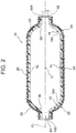
- the arrows X in FIG. 1 indicate sides farther away from a center O of a pressure vessel 10 (vessel main body 12) in an axial direction of a central axis CL of the pressure vessel 10, and these farther side will be referred to as "axial end sides.”
- axial end sides the side of an axial end of the central axis CL on the side of a first domed part 16 of the pressure vessel 10 to be described later will also be referred to as a "first axial end side”
- the side of an axial end of the central axis CL on the side of a second domed part 18 of the pressure vessel 10 will also be referred to as a "second axial end side.”
- the side nearer to the center O of the pressure vessel 10 (vessel main body 12) will be referred to as an "axial center side.”
- the pressure vessel 10 according to this embodiment is intended, for example, to be filled with hydrogen as fuel and installed in a fuel cell vehicle (not shown
- the pressure vessel 10 has the vessel main body 12 called a liner.
- the vessel main body 12 is blow-molded from a liquid crystal resin material that is excellent in both gas barrier property and dimensional stability.
- the vessel main body 12 has a cylindrical straight body part 14, and the first domed part 16 and the second domed part 18 respectively including a first hemispherical portion 16A and a second hemispherical portion 18A that have substantially hemispherical shapes and are integrally formed one at each end of the straight body part 14.
- first hemispherical portion 16A and the second hemispherical portion 18A will also be collectively referred to as “hemispherical portions 16A, 18A,” and the first domed part 16 and the second domed part 18 will also be collectively referred to as “domed parts 16, 18.”
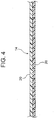
- the pressure vessel 10 has reinforcing fibers 20, in the shape of a tape with a predetermined width, wound in layers around an outer circumferential surface of the straight body part 14 and outer circumferential surfaces of the domed parts 16, 18.
- the reinforcing fibers 20 are made of fiber-reinforced plastics (FRP) containing glass fibers, carbon fibers, aramid fibers, or the like, and an FRP layer as a fiber-reinforced-plastic layer is formed on an outer circumferential surface of the vessel main body 12.
- FRP fiber-reinforced plastics
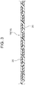
- the reinforcing fibers 20 are wound so as to be interlaced with each other (hereinafter also referred to as "braid winding") around the outer circumferential surface of the first domed part 16, and a first reinforced section 26 that is an FRP layer is formed by the braid-wound reinforcing fibers 20.
- the reinforcing fibers 20 are wound so as to be interlaced with each other (hereinafter also referred to as "braid winding") around the outer circumferential surface of the second domed part 18, and a third reinforced section 28 that is an FRP layer is formed by the braid-wound reinforcing fibers 20.
- the reinforcing fibers 20 are helically wound (hereinafter also referred to as "helical winding") around the outer circumferential surface of the straight body part 14, and a second reinforced section 24 that is an FRP layer is formed by the helically wound reinforcing fibers 20.
- the helical winding refers to winding the reinforcing fibers 20 around the entire outer circumferential surface of the straight body part 14 at a predetermined winding angle ⁇ (- ⁇ ) relative to the central axis CL of the vessel main body 12, and then further winding the reinforcing fibers 20 on top of that (on top of the reinforcing fibers 20 having been wound at the angle - ⁇ ) at the predetermined winding angle ⁇ (+0) relative to the central axis CL of the vessel main body 12.
- the second reinforced section 24 is formed as the reinforcing fibers 20 are wound at the predetermined winding angles - ⁇ and + ⁇ in at least two layers around the outer circumferential surface of the straight body part 14.
- the braid winding refers to winding the reinforcing fibers 20 so as to be interlaced with each other, and winding the reinforcing fibers 20 at the predetermined winding angles - ⁇ and + ⁇ relative to the central axis CL of the vessel main body 12.
- the winding angle ⁇ is an angle derived from a stress occurring when a predetermined internal pressure is acting on the straight body part 14, and is an angle attributable to the fact that a stress acting on the vessel main body 12 in a circumferential direction is twice as large as a stress acting thereon in a longitudinal axial direction.
- the domed parts 16, 18 require a lower level of reinforcement than the straight body part 14. Therefore, the braid winding that has lower strength than the helical winding is used for the domed parts 16, 18, while the helical winding that has higher strength than the braid winding is used for the straight body part 14.
- a position at which the first reinforced section 26 transitions to the second reinforced section 24 is located on a first border 22A between the straight body part 14 and the first domed part 16 (on a first imaginary circumference 32 to be described later), as seen from a direction orthogonal to the axial direction of the central axis CL of the vessel main body 12.
- the position of transition from the first reinforced section 26 to the second reinforced section 24 is not limited to this position.
- the first reinforced section 26 may transition to the second reinforced section 24 on the side of the first axial end of the central axis CL from the first border 22A between the straight body part 14 and the first domed part 16 (at the position indicated by the long dashed-short dashed line T), as seen from the direction orthogonal to the axial direction of the central axis CL of the vessel main body 12.
- the first border 22A here refers to the first imaginary circumference 32 passing through an imaginary border point Ks between the straight body part 14 and the first domed part 16 (a point at which the curvature becomes zero).
- the position at which the first reinforced section 26 transitions to the second reinforced section 24 is located on the axial center side from a first specific portion 30 in an outer circumferential surface of the first hemispherical portion 16A that is determined by the winding angle ⁇ ( ⁇ ), relative to the central axis CL, of the reinforcing fibers 20 wound around the straight body part 14, as seen from the direction orthogonal to the axial direction of the central axis CL of the vessel main body 12.
- the first specific portion 30 here refers to a second imaginary circumference 34 passing through an imaginary intersection point Kp between the outer circumferential surface of the first hemispherical portion 16A and a first axial end-side edge 20B of reinforcing fibers 20A (represented by dotted portions), of the reinforcing fibers 20 wound at the winding angle ⁇ , that passes through an intersection point Cp between the first imaginary circumference 32 and the central axis CL, as seen from the direction orthogonal to the axial direction of the central axis CL of the vessel main body 12.
- the position of transition from the first reinforced section 26 to the second reinforced section 24 may be any position inside a region E between the second imaginary circumference 34 and the first imaginary circumference 32 (the region on the axial center side from the first specific portion 30 including the first specific portion 30 and on the first axial end side from the first border 22A including the first border 22A).
- the same description applies to transition from the second reinforced section 24 to the third reinforced section 28 (not shown).
- the second reinforced section 24 transitions to the third reinforced section 28 on the side of the second axial end of the central axis CL from a second border 22B between the straight body part 14 and the second domed part 18.
- the position of transition is not limited to this position.
- the second reinforced section 24 may transition to the third reinforced section 28 on the side of the axial center of the central axis CL from a second specific portion in an outer circumferential surface of the second hemispherical portion 18A that is determined by the winding angle ⁇ (+ ⁇ ), relative to the central axis CL, of the reinforcing fibers 20 wound around the straight body part 14.
- the first domed part 16 includes, at an axial center portion thereof, a first cylindrical portion 16B protruding toward the first axial end of the central axis CL of the vessel main body 12.
- the second domed part 18 includes, at an axial center portion thereof, a second cylindrical portion 18B protruding toward the second axial end of the central axis CL of the vessel main body 12.
- a sealing plug 46 is fitted in the first cylindrical portion 16B
- a closure plug 48 is fitted in the second cylindrical portion 18B and a valve (not shown) is attached to the closure plug 48.
- an angle ⁇ , relative to the central axis CL, of an imaginary tangential line Kt passing through a terminal end Np, on the side of the first hemispherical portion 16A, of a first curved surface 36 of the first domed part 16 continuing from the first cylindrical portion 16B to the first hemispherical portion 16A is equal to or smaller than the winding angle ⁇ , relative to the central axis CL, of the reinforcing fibers 20 wound around the straight body part 14 ( ⁇ ⁇ ⁇ ), as seen from the direction orthogonal to the axial direction of the central axis CL of the vessel main body 12.
- an angle ⁇ , relative to the central axis CL, of an imaginary tangential line Kt passing through a terminal end Np, on the side of the second hemispherical portion 18A, of a second curved surface 38 (see FIG. 2 ) of the second domed part 18 continuing from the second cylindrical portion 18B to the second hemispherical portion 18A is equal to or smaller than the winding angle ⁇ , relative to the central axis CL, of the reinforcing fibers 20 wound around the straight body part 14 ( ⁇ ⁇ ⁇ ).
- the "terminal end Np" here includes an inflection point between the first curved surface 36 and the first hemispherical portion 16A and an inflection point between the second curved surface 38 and the second hemispherical portion 18A.
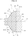
- the reinforcing fibers 20 are wound around the outer circumferential surface of the vessel main body 12 by a publicly known manufacturing apparatus 40.
- the manufacturing apparatus 40 has pluralities of bobbins 42, 44 disposed in two rows on a circumference, and the reinforcing fibers 20 reeled out from the bobbins 42, 44 in the respective rows are sequentially wound around the outer circumferential surface of the first domed part 16, the outer circumferential surface of the straight body part 14, and the outer circumferential surface of the second domed part 18 of the vessel main body 12 that is moved in the axial direction of the central axis CL (the leftward direction in FIG. 8 ).
- the bobbins 42 linked together by the solid line and the bobbins 44 linked together by the imaginary line are disposed in a circumferential direction so as to alternate with each other on a radially inner side and a radially outer side.
- the manufacturing apparatus 40 is driven such that the bobbins 42 linked together by the solid line and the bobbins 44 linked together by the imaginary line are moved from the radially inner side to the radially outer side and from the radially outer side to the radially inner side, so as to sequentially alternate with each other, while the bobbins 42, 44 are moved in the opposite directions (opposite circumferential directions).
- the solid line represents a moving path of the bobbins 42
- the imaginary line represents a moving path of the bobbins 44.
- the bobbins 42 linked together by the solid line and the bobbins 44 linked together by the imaginary line are disposed in the circumferential direction, respectively on the radially outer side and the radially inner side.
- the manufacturing apparatus 40 is driven such that the bobbins 42 linked together by the solid line and the bobbins 44 linked together by the imaginary line are moved in the opposite directions (opposite circumferential directions).
- the pressure vessel 10 is formed as the reinforcing fibers 20 are wound around the outer circumferential surface of the vessel main body 12. Specifically, the reinforcing fibers 20 are sequentially reeled out from the bobbins 42, 44, and first, the reinforcing fibers 20 are braid-wound around the outer circumferential surface of the first domed part 16 to form the first reinforced section 26 (first step).
- the reinforcing fibers 20 are less likely to slip over the outer circumferential surface of the first domed part 16, so that it is not necessary to wind the reinforcing fibers 20 at such a winding angle that the reinforcing fibers 20 run along a geodesic line (the shortest route).
- flexibility is allowed in setting the angle at which the reinforcing fibers 20 are wound around the vessel main body 12 (straight body part 14), and desired strength can be achieved by a required minimum amount of reinforcing fibers 20.
- the manufacturing cost and the mass of the pressure vessel 10 can be kept down.
- the reinforcing fibers 20 are helically wound around the outer circumferential surface of the straight body part 14 to form the second reinforced section 24 (second step).
- the transition from the braid winding in the first domed part 16 to the helical winding in the straight body part 14 is made in the region E between the second imaginary circumference 34 (first specific portion 30) and the first imaginary circumference 32 (first border 22A).
- the second imaginary circumference 34 includes the imaginary intersection point Kp that is determined by the optimal winding angle ⁇ of the reinforcing fibers 20 for the straight body part 14.
- the reinforcing fibers 20 can transition smoothly from the braid winding to the helical winding at the same winding angle ⁇ .
- the reinforcing fibers 20 are wound with good continuity from the outer circumferential surface of the first hemispherical portion 16A to the outer circumferential surface of the straight body part 14, which can improve the productivity of the pressure vessel 10.
- the angle ⁇ , relative to the central axis CL, of the imaginary tangential line Kt passing through the terminal end Np, on the side of the first hemispherical portion 16A, of the first curved surface 36 continuing from the first cylindrical portion 16B to the first hemispherical portion 16A is equal to or smaller than the winding angle ⁇ , relative to the central axis CL, of the reinforcing fibers 20 wound around the straight body part 14 (see FIG. 7 ).
- the helical winding instead of the braid winding is used for the straight body part 14
- the required amount of reinforcing fibers 20 can be reduced compared with if the braid winding is used also for the straight body part 14.
- the manufacturing cost and the mass of the pressure vessel 10 can be further kept down.
- the reinforcing fibers 20 are thus not bent in the straight body part 14, the strength of the second reinforced section 24 that most requires strength can be appropriately secured (The straight body part 14 can be appropriately reinforced).
- the reinforcing fibers 20 are braid-wound around the outer circumferential surface of the second domed part 18 to form the third reinforced section 28 (third step).
- the reinforcing fibers 20 are less likely to slip also over the outer circumferential surface of the second domed part 18, so that it is not necessary to wind the reinforcing fibers 20 at such a winding angle that the reinforcing fibers 20 run along a geodesic line (the shortest route).
- the transition from the helical winding in the straight body part 14 to the braid winding in the second domed part 18 is also made in the region of the second domed part 18 between a first imaginary circumference (second border 22B) similar to the first imaginary circumference 32 and a second imaginary circumference (second specific portion) similar to the second imaginary circumference 34.
- the second imaginary circumference of the second domed part 18 similar to the second imaginary circumference 34 includes an imaginary intersection point that is determined by the optimal winding angle ⁇ of the reinforcing fibers 20 for the straight body part 14.
- the reinforcing fibers 20 can transition smoothly from the helical winding to the braid winding at the same winding angle ⁇ .
- the reinforcing fibers 20 are wound with good continuity from the outer circumferential surface of the straight body part 14 to the outer circumferential surface of the second hemispherical portion 18A, which can improve the productivity of the pressure vessel 10.
- the angle, relative to the central axis CL, of the imaginary tangential line passing through the terminal end, on the side of the second hemispherical portion 18A, of the second curved surface 38 continuing from the second cylindrical portion 18B to the second hemispherical portion 18A is equal to or smaller than the winding angle ⁇ , relative to the central axis CL, of the reinforcing fibers 20 wound around the straight body part 14.
- the winding angle ⁇ of the reinforcing fibers 20 wound around the straight body part 14 is within the range of 54.7 degrees ⁇ 10 degrees.
- This value "54.7 degrees” is an angle (equilibrium angle) derived from a stress occurring when a predetermined internal pressure is acting on the straight body part 14.
- ⁇ 10 degrees is a tolerance allowed in actually winding the reinforcing fibers 20.
- the straight body part 14 can be reinforced more appropriately, compared with if the winding angle ⁇ of the reinforcing fibers 20 wound around the straight body part 14 is not within the range of 54.7 degrees ⁇ 10 degrees.
- the reinforcing fibers 20 When the reinforcing fibers 20 have been thus wound around the vessel main body 12 and the first reinforced section 26, the second reinforced section 24, and the third reinforced section 28 have been formed, the reinforcing fibers 20 forming the first reinforced section 26, the second reinforced section 24, and the third reinforced section 28 are impregnated with a thermosetting resin and then heated to harden the thermosetting resin.
- the pressure vessel 10 that has excellent corrosion resistance, can achieve weight reduction and cost reduction, and is easy to transport and handle can be produced.
- the pressure vessel 10 according to the embodiment has been described above based on the drawings, the pressure vessel 10 according to the embodiment is not limited to that shown in the drawings, and design changes can be appropriately made thereto within the scope of the gist of the present invention.
- the vessel main body 12 is not limited to that made of a liquid crystal resin.
- the vessel main body 12 may be made of another synthetic resin having a gas barrier property, such as high-density polyethylene, or may be made of light metal, such as an aluminum alloy.
- the vessel main body 12 is not limited to that produced by blow molding, and may instead be produced by injection molding etc.
Landscapes
- Engineering & Computer Science (AREA)
- General Engineering & Computer Science (AREA)
- Mechanical Engineering (AREA)
- Filling Or Discharging Of Gas Storage Vessels (AREA)
- Pressure Vessels And Lids Thereof (AREA)
Applications Claiming Priority (1)
| Application Number | Priority Date | Filing Date | Title |
|---|---|---|---|
| JP2018150690A JP7176287B2 (ja) | 2018-08-09 | 2018-08-09 | 圧力容器及びその製造方法 |
Publications (2)
| Publication Number | Publication Date |
|---|---|
| EP3608580A1 true EP3608580A1 (de) | 2020-02-12 |
| EP3608580B1 EP3608580B1 (de) | 2024-01-10 |
Family
ID=66676317
Family Applications (1)
| Application Number | Title | Priority Date | Filing Date |
|---|---|---|---|
| EP19177182.3A Active EP3608580B1 (de) | 2018-08-09 | 2019-05-29 | Druckbehälter und herstellungsverfahren dafür |
Country Status (6)
| Country | Link |
|---|---|
| US (1) | US11421824B2 (de) |
| EP (1) | EP3608580B1 (de) |
| JP (1) | JP7176287B2 (de) |
| KR (1) | KR102240301B1 (de) |
| CN (1) | CN110822280B (de) |
| RU (1) | RU2708751C1 (de) |
Families Citing this family (15)
| Publication number | Priority date | Publication date | Assignee | Title |
|---|---|---|---|---|
| JP6627961B2 (ja) * | 2016-03-04 | 2020-01-15 | 日産自動車株式会社 | 高圧ガス貯蔵容器、および高圧ガス貯蔵容器の製造方法 |
| KR20180017377A (ko) * | 2016-08-09 | 2018-02-21 | 현대자동차주식회사 | 고압 용기 |
| JP7131523B2 (ja) * | 2019-10-16 | 2022-09-06 | トヨタ自動車株式会社 | モジュール |
| KR102401745B1 (ko) * | 2019-11-27 | 2022-05-25 | 롯데케미칼 주식회사 | 후프층 및 헬리컬층이 와인딩된 고압탱크 및 그 제작방법 |
| JP7259734B2 (ja) * | 2019-12-25 | 2023-04-18 | トヨタ自動車株式会社 | 高圧タンクの製造方法 |
| DE102020124545A1 (de) * | 2020-09-21 | 2022-03-24 | Bayerische Motoren Werke Aktiengesellschaft | Druckbehälter und Druckbehältersystem |
| KR102923154B1 (ko) * | 2020-12-01 | 2026-02-09 | 현대자동차주식회사 | 압력용기 및 그 제조방법 |
| WO2022138996A1 (ko) * | 2020-12-21 | 2022-06-30 | 일진복합소재 주식회사 | 비정형 수소저장탱크 및 이의 제조방법 |
| CN113128088B (zh) * | 2021-04-02 | 2022-09-20 | 华东师范大学 | 一种用于复合材料压力容器的缠绕线型设计方法及系统 |
| US12358365B1 (en) * | 2021-05-07 | 2025-07-15 | Agility Fuel Systems Llc | Vehicles having composite interwoven gas containment assemblies |
| JP7533399B2 (ja) * | 2021-08-26 | 2024-08-14 | トヨタ自動車株式会社 | タンクおよびその製造方法 |
| JP7501471B2 (ja) * | 2021-08-26 | 2024-06-18 | トヨタ自動車株式会社 | タンクの製造方法および製造装置 |
| JP7711622B2 (ja) * | 2022-04-26 | 2025-07-23 | トヨタ自動車株式会社 | タンク製造方法 |
| JP7687274B2 (ja) * | 2022-05-19 | 2025-06-03 | トヨタ自動車株式会社 | ガスタンクおよびその製造方法 |
| JP7652135B2 (ja) | 2022-05-19 | 2025-03-27 | トヨタ自動車株式会社 | ガスタンクおよびその製造方法 |
Citations (8)
| Publication number | Priority date | Publication date | Assignee | Title |
|---|---|---|---|---|
| JP2004263827A (ja) | 2003-03-04 | 2004-09-24 | Mitsubishi Rayon Co Ltd | 圧力容器およびその製造方法 |
| EP1520683A2 (de) * | 2003-10-01 | 2005-04-06 | Fuji Jukogyo Kabushiki Kaisha | Verfahren zur Herstellung eines Druckbehälters |
| US20050076995A1 (en) * | 2003-10-03 | 2005-04-14 | Shugo Yasui | Pressure container manufacturing method |
| US20120048862A1 (en) * | 2009-04-10 | 2012-03-01 | Toyota Jidosha Kabushiki Kaisha | Tank and manufacturing method thereof |
| WO2016020972A1 (ja) * | 2014-08-04 | 2016-02-11 | 日産自動車株式会社 | 高圧タンク及び高圧タンク製造方法 |
| DE202015105815U1 (de) * | 2015-09-24 | 2016-12-28 | Rehau Ag + Co | Druckbehälter zur Speicherung von Gasen oder Flüssigkeiten unter Drücken oberhalb von 200 bar |
| WO2017073108A1 (ja) * | 2015-10-26 | 2017-05-04 | サムテック株式会社 | 複合容器 |
| WO2018096905A1 (ja) * | 2016-11-24 | 2018-05-31 | 東レ株式会社 | 圧力容器の製造方法 |
Family Cites Families (24)
| Publication number | Priority date | Publication date | Assignee | Title |
|---|---|---|---|---|
| JPS5936146B2 (ja) * | 1978-02-23 | 1984-09-01 | 川重防災工業株式会社 | 圧力容器 |
| DE3631975A1 (de) * | 1986-09-19 | 1988-04-07 | Eugen Ehs | Trocknerbehaelter fuer eine klimaanlage |
| JP3000868B2 (ja) * | 1994-10-04 | 2000-01-17 | 村田機械株式会社 | ボンベの製造方法 |
| US5822838A (en) * | 1996-02-01 | 1998-10-20 | Lockheed Martin Corporation | High performance, thin metal lined, composite overwrapped pressure vessel |
| NL1014290C2 (nl) * | 2000-02-04 | 2001-08-07 | Advanced Lightweight Const Gro | Vezelversterkt drukvat en werkwijze voor het maken van een vezelversterkt drukvat. |
| CN1676985A (zh) | 2004-03-30 | 2005-10-05 | 华群 | 纤维增强型压力容器及其用途 |
| JP2005308055A (ja) | 2004-04-20 | 2005-11-04 | Murata Mach Ltd | Frp製圧力容器 |
| JP2006132746A (ja) * | 2004-11-09 | 2006-05-25 | Toyota Industries Corp | 圧力容器及び水素貯蔵タンク並びに圧力容器の製造方法 |
| JP2008032088A (ja) * | 2006-07-27 | 2008-02-14 | Toyota Motor Corp | タンク |
| US8074826B2 (en) * | 2008-06-24 | 2011-12-13 | Composite Technology Development, Inc. | Damage and leakage barrier in all-composite pressure vessels and storage tanks |
| RU2393375C2 (ru) * | 2008-08-27 | 2010-06-27 | Сергей Владимирович ЛУКЬЯНЕЦ | Баллон высокого давления |
| US20130206778A1 (en) * | 2010-02-01 | 2013-08-15 | Sergei Vladimirovich Lukyanets | Metal composite pressure cylinder |
| JP5408351B2 (ja) * | 2010-06-08 | 2014-02-05 | トヨタ自動車株式会社 | 高圧タンクおよび高圧タンクの製造方法 |
| DE112011105750B9 (de) * | 2011-10-18 | 2018-08-09 | Toyota Jidosha Kabushiki Kaisha | Herstellungsverfahren für einen Hochdruck-Gastank |
| RU2526999C1 (ru) * | 2013-07-30 | 2014-08-27 | Открытое акционерное общество Центральный научно-исследовательский институт специального машиностроения | Оболочка из композиционных материалов для высокого внутреннего давления |
| DE102014223127A1 (de) | 2014-11-12 | 2016-05-12 | Bayerische Motoren Werke Aktiengesellschaft | Druckbehälter, Verfahren zur Herstellung eines Druckbehälters sowie Flechtmaschine |
| DE202016100754U1 (de) | 2016-02-12 | 2016-02-23 | Enrichment Technology Company Ltd. Zweigniederlassung Deutschland | Polkappenverstärkter Druckbehälter |
| JP6381563B2 (ja) * | 2016-03-01 | 2018-08-29 | 株式会社日本製鋼所 | 圧力容器およびフープラップ複合圧力容器 |
| JP6627961B2 (ja) * | 2016-03-04 | 2020-01-15 | 日産自動車株式会社 | 高圧ガス貯蔵容器、および高圧ガス貯蔵容器の製造方法 |
| JP6874474B2 (ja) * | 2017-03-30 | 2021-05-19 | トヨタ自動車株式会社 | タンクの製造装置および製造方法 |
| US10619794B2 (en) * | 2018-03-13 | 2020-04-14 | Ford Global Technologies, Llc | Pressurized-fluid storage device |
| CN112166282B (zh) * | 2018-06-26 | 2021-11-26 | 全耐塑料高级创新研究公司 | 具有增强内衬的复合材料压力容器及其制造方法 |
| EP3831583A4 (de) * | 2018-07-30 | 2021-09-22 | Kabushiki Kaisha Toyota Jidoshokki | Rohrförmiger frp-körper und verfahren zur herstellung des rohrförmigen frp-körpers |
| JP7035976B2 (ja) * | 2018-11-15 | 2022-03-15 | トヨタ自動車株式会社 | 高圧タンクおよびその取付け構造 |
-
2018
- 2018-08-09 JP JP2018150690A patent/JP7176287B2/ja active Active
-
2019
- 2019-05-16 RU RU2019114950A patent/RU2708751C1/ru active
- 2019-05-17 KR KR1020190057851A patent/KR102240301B1/ko active Active
- 2019-05-21 CN CN201910424332.5A patent/CN110822280B/zh active Active
- 2019-05-29 US US16/424,967 patent/US11421824B2/en active Active
- 2019-05-29 EP EP19177182.3A patent/EP3608580B1/de active Active
Patent Citations (8)
| Publication number | Priority date | Publication date | Assignee | Title |
|---|---|---|---|---|
| JP2004263827A (ja) | 2003-03-04 | 2004-09-24 | Mitsubishi Rayon Co Ltd | 圧力容器およびその製造方法 |
| EP1520683A2 (de) * | 2003-10-01 | 2005-04-06 | Fuji Jukogyo Kabushiki Kaisha | Verfahren zur Herstellung eines Druckbehälters |
| US20050076995A1 (en) * | 2003-10-03 | 2005-04-14 | Shugo Yasui | Pressure container manufacturing method |
| US20120048862A1 (en) * | 2009-04-10 | 2012-03-01 | Toyota Jidosha Kabushiki Kaisha | Tank and manufacturing method thereof |
| WO2016020972A1 (ja) * | 2014-08-04 | 2016-02-11 | 日産自動車株式会社 | 高圧タンク及び高圧タンク製造方法 |
| DE202015105815U1 (de) * | 2015-09-24 | 2016-12-28 | Rehau Ag + Co | Druckbehälter zur Speicherung von Gasen oder Flüssigkeiten unter Drücken oberhalb von 200 bar |
| WO2017073108A1 (ja) * | 2015-10-26 | 2017-05-04 | サムテック株式会社 | 複合容器 |
| WO2018096905A1 (ja) * | 2016-11-24 | 2018-05-31 | 東レ株式会社 | 圧力容器の製造方法 |
Also Published As
| Publication number | Publication date |
|---|---|
| JP7176287B2 (ja) | 2022-11-22 |
| JP2020026817A (ja) | 2020-02-20 |
| EP3608580B1 (de) | 2024-01-10 |
| CN110822280B (zh) | 2022-01-11 |
| US20200049312A1 (en) | 2020-02-13 |
| KR102240301B1 (ko) | 2021-04-14 |
| BR102019009873A2 (pt) | 2020-03-03 |
| US11421824B2 (en) | 2022-08-23 |
| RU2708751C1 (ru) | 2019-12-11 |
| CN110822280A (zh) | 2020-02-21 |
| KR20200018223A (ko) | 2020-02-19 |
Similar Documents
| Publication | Publication Date | Title |
|---|---|---|
| EP3608580B1 (de) | Druckbehälter und herstellungsverfahren dafür | |
| JP4588307B2 (ja) | 耐圧容器製造方法 | |
| CN102388256B (zh) | 罐及其制造方法 | |
| US10487981B2 (en) | High-pressure composite vessel and the method of manufacturing high-pressure composite vessel | |
| US20160341359A1 (en) | High pressure tank, method of manufacturing high pressure tank and method of designing liner shape | |
| JP7439744B2 (ja) | 高圧タンクおよびその製造方法 | |
| JP7314771B2 (ja) | 圧力容器及びその製造方法 | |
| US10619794B2 (en) | Pressurized-fluid storage device | |
| US10456994B2 (en) | Composite container | |
| CN111503265B (zh) | 高压罐及制造高压罐的方法 | |
| JP6256190B2 (ja) | 高圧ガスタンクの製造方法 | |
| KR102347694B1 (ko) | 압력 용기의 제조 방법 | |
| JP7093010B2 (ja) | 高圧タンク | |
| US20170241591A1 (en) | High-pressure tank and method of manufacturing high-pressure tank | |
| JP2005106142A (ja) | 圧力容器 | |
| CN115992928A (zh) | 高压罐及高压罐的制造方法 | |
| JP7318781B2 (ja) | 圧力容器及びその製造方法 | |
| JP2020128010A (ja) | 高圧タンクの製造方法 | |
| JP6733228B2 (ja) | 圧力容器 | |
| JP2020131430A (ja) | 高圧タンクの製造方法 | |
| BR102019009873B1 (pt) | Vaso de pressão e método de fabricação do mesmo | |
| JP2018010429A (ja) | 高圧タンクにおける繊維堆積含有率の計算方法 | |
| KR102717282B1 (ko) | 두개의 원통형 섹션들을 갖는 탱크 라이너 | |
| JP2023032013A (ja) | タンクおよびその製造方法 |
Legal Events
| Date | Code | Title | Description |
|---|---|---|---|
| PUAI | Public reference made under article 153(3) epc to a published international application that has entered the european phase |
Free format text: ORIGINAL CODE: 0009012 |
|
| STAA | Information on the status of an ep patent application or granted ep patent |
Free format text: STATUS: REQUEST FOR EXAMINATION WAS MADE |
|
| 17P | Request for examination filed |
Effective date: 20190529 |
|
| AK | Designated contracting states |
Kind code of ref document: A1 Designated state(s): AL AT BE BG CH CY CZ DE DK EE ES FI FR GB GR HR HU IE IS IT LI LT LU LV MC MK MT NL NO PL PT RO RS SE SI SK SM TR |
|
| AX | Request for extension of the european patent |
Extension state: BA ME |
|
| STAA | Information on the status of an ep patent application or granted ep patent |
Free format text: STATUS: EXAMINATION IS IN PROGRESS |
|
| 17Q | First examination report despatched |
Effective date: 20220331 |
|
| GRAP | Despatch of communication of intention to grant a patent |
Free format text: ORIGINAL CODE: EPIDOSNIGR1 |
|
| STAA | Information on the status of an ep patent application or granted ep patent |
Free format text: STATUS: GRANT OF PATENT IS INTENDED |
|
| INTG | Intention to grant announced |
Effective date: 20230804 |
|
| GRAS | Grant fee paid |
Free format text: ORIGINAL CODE: EPIDOSNIGR3 |
|
| GRAA | (expected) grant |
Free format text: ORIGINAL CODE: 0009210 |
|
| STAA | Information on the status of an ep patent application or granted ep patent |
Free format text: STATUS: THE PATENT HAS BEEN GRANTED |
|
| AK | Designated contracting states |
Kind code of ref document: B1 Designated state(s): AL AT BE BG CH CY CZ DE DK EE ES FI FR GB GR HR HU IE IS IT LI LT LU LV MC MK MT NL NO PL PT RO RS SE SI SK SM TR |
|
| REG | Reference to a national code |
Ref country code: GB Ref legal event code: FG4D |
|
| REG | Reference to a national code |
Ref country code: CH Ref legal event code: EP |
|
| REG | Reference to a national code |
Ref country code: DE Ref legal event code: R096 Ref document number: 602019044756 Country of ref document: DE |
|
| REG | Reference to a national code |
Ref country code: IE Ref legal event code: FG4D |
|
| REG | Reference to a national code |
Ref country code: LT Ref legal event code: MG9D |
|
| REG | Reference to a national code |
Ref country code: NL Ref legal event code: MP Effective date: 20240110 |
|
| P01 | Opt-out of the competence of the unified patent court (upc) registered |
Effective date: 20240419 |
|
| REG | Reference to a national code |
Ref country code: DE Ref legal event code: R084 Ref document number: 602019044756 Country of ref document: DE |
|
| REG | Reference to a national code |
Ref country code: AT Ref legal event code: MK05 Ref document number: 1649143 Country of ref document: AT Kind code of ref document: T Effective date: 20240110 |
|
| PG25 | Lapsed in a contracting state [announced via postgrant information from national office to epo] |
Ref country code: NL Free format text: LAPSE BECAUSE OF FAILURE TO SUBMIT A TRANSLATION OF THE DESCRIPTION OR TO PAY THE FEE WITHIN THE PRESCRIBED TIME-LIMIT Effective date: 20240110 |
|
| PG25 | Lapsed in a contracting state [announced via postgrant information from national office to epo] |
Ref country code: NL Free format text: LAPSE BECAUSE OF FAILURE TO SUBMIT A TRANSLATION OF THE DESCRIPTION OR TO PAY THE FEE WITHIN THE PRESCRIBED TIME-LIMIT Effective date: 20240110 |
|
| PG25 | Lapsed in a contracting state [announced via postgrant information from national office to epo] |
Ref country code: IS Free format text: LAPSE BECAUSE OF FAILURE TO SUBMIT A TRANSLATION OF THE DESCRIPTION OR TO PAY THE FEE WITHIN THE PRESCRIBED TIME-LIMIT Effective date: 20240510 |
|
| PG25 | Lapsed in a contracting state [announced via postgrant information from national office to epo] |
Ref country code: LT Free format text: LAPSE BECAUSE OF FAILURE TO SUBMIT A TRANSLATION OF THE DESCRIPTION OR TO PAY THE FEE WITHIN THE PRESCRIBED TIME-LIMIT Effective date: 20240110 |
|
| PG25 | Lapsed in a contracting state [announced via postgrant information from national office to epo] |
Ref country code: GR Free format text: LAPSE BECAUSE OF FAILURE TO SUBMIT A TRANSLATION OF THE DESCRIPTION OR TO PAY THE FEE WITHIN THE PRESCRIBED TIME-LIMIT Effective date: 20240411 |
|
| PG25 | Lapsed in a contracting state [announced via postgrant information from national office to epo] |
Ref country code: HR Free format text: LAPSE BECAUSE OF FAILURE TO SUBMIT A TRANSLATION OF THE DESCRIPTION OR TO PAY THE FEE WITHIN THE PRESCRIBED TIME-LIMIT Effective date: 20240110 Ref country code: RS Free format text: LAPSE BECAUSE OF FAILURE TO SUBMIT A TRANSLATION OF THE DESCRIPTION OR TO PAY THE FEE WITHIN THE PRESCRIBED TIME-LIMIT Effective date: 20240410 |
|
| PG25 | Lapsed in a contracting state [announced via postgrant information from national office to epo] |
Ref country code: ES Free format text: LAPSE BECAUSE OF FAILURE TO SUBMIT A TRANSLATION OF THE DESCRIPTION OR TO PAY THE FEE WITHIN THE PRESCRIBED TIME-LIMIT Effective date: 20240110 |
|
| PG25 | Lapsed in a contracting state [announced via postgrant information from national office to epo] |
Ref country code: AT Free format text: LAPSE BECAUSE OF FAILURE TO SUBMIT A TRANSLATION OF THE DESCRIPTION OR TO PAY THE FEE WITHIN THE PRESCRIBED TIME-LIMIT Effective date: 20240110 |
|
| PG25 | Lapsed in a contracting state [announced via postgrant information from national office to epo] |
Ref country code: RS Free format text: LAPSE BECAUSE OF FAILURE TO SUBMIT A TRANSLATION OF THE DESCRIPTION OR TO PAY THE FEE WITHIN THE PRESCRIBED TIME-LIMIT Effective date: 20240410 Ref country code: NO Free format text: LAPSE BECAUSE OF FAILURE TO SUBMIT A TRANSLATION OF THE DESCRIPTION OR TO PAY THE FEE WITHIN THE PRESCRIBED TIME-LIMIT Effective date: 20240410 Ref country code: LT Free format text: LAPSE BECAUSE OF FAILURE TO SUBMIT A TRANSLATION OF THE DESCRIPTION OR TO PAY THE FEE WITHIN THE PRESCRIBED TIME-LIMIT Effective date: 20240110 Ref country code: IS Free format text: LAPSE BECAUSE OF FAILURE TO SUBMIT A TRANSLATION OF THE DESCRIPTION OR TO PAY THE FEE WITHIN THE PRESCRIBED TIME-LIMIT Effective date: 20240510 Ref country code: HR Free format text: LAPSE BECAUSE OF FAILURE TO SUBMIT A TRANSLATION OF THE DESCRIPTION OR TO PAY THE FEE WITHIN THE PRESCRIBED TIME-LIMIT Effective date: 20240110 Ref country code: GR Free format text: LAPSE BECAUSE OF FAILURE TO SUBMIT A TRANSLATION OF THE DESCRIPTION OR TO PAY THE FEE WITHIN THE PRESCRIBED TIME-LIMIT Effective date: 20240411 Ref country code: ES Free format text: LAPSE BECAUSE OF FAILURE TO SUBMIT A TRANSLATION OF THE DESCRIPTION OR TO PAY THE FEE WITHIN THE PRESCRIBED TIME-LIMIT Effective date: 20240110 Ref country code: BG Free format text: LAPSE BECAUSE OF FAILURE TO SUBMIT A TRANSLATION OF THE DESCRIPTION OR TO PAY THE FEE WITHIN THE PRESCRIBED TIME-LIMIT Effective date: 20240110 Ref country code: AT Free format text: LAPSE BECAUSE OF FAILURE TO SUBMIT A TRANSLATION OF THE DESCRIPTION OR TO PAY THE FEE WITHIN THE PRESCRIBED TIME-LIMIT Effective date: 20240110 |
|
| PG25 | Lapsed in a contracting state [announced via postgrant information from national office to epo] |
Ref country code: PL Free format text: LAPSE BECAUSE OF FAILURE TO SUBMIT A TRANSLATION OF THE DESCRIPTION OR TO PAY THE FEE WITHIN THE PRESCRIBED TIME-LIMIT Effective date: 20240110 Ref country code: PT Free format text: LAPSE BECAUSE OF FAILURE TO SUBMIT A TRANSLATION OF THE DESCRIPTION OR TO PAY THE FEE WITHIN THE PRESCRIBED TIME-LIMIT Effective date: 20240510 |
|
| PG25 | Lapsed in a contracting state [announced via postgrant information from national office to epo] |
Ref country code: SE Free format text: LAPSE BECAUSE OF FAILURE TO SUBMIT A TRANSLATION OF THE DESCRIPTION OR TO PAY THE FEE WITHIN THE PRESCRIBED TIME-LIMIT Effective date: 20240110 Ref country code: PT Free format text: LAPSE BECAUSE OF FAILURE TO SUBMIT A TRANSLATION OF THE DESCRIPTION OR TO PAY THE FEE WITHIN THE PRESCRIBED TIME-LIMIT Effective date: 20240510 Ref country code: PL Free format text: LAPSE BECAUSE OF FAILURE TO SUBMIT A TRANSLATION OF THE DESCRIPTION OR TO PAY THE FEE WITHIN THE PRESCRIBED TIME-LIMIT Effective date: 20240110 Ref country code: LV Free format text: LAPSE BECAUSE OF FAILURE TO SUBMIT A TRANSLATION OF THE DESCRIPTION OR TO PAY THE FEE WITHIN THE PRESCRIBED TIME-LIMIT Effective date: 20240110 |
|
| PG25 | Lapsed in a contracting state [announced via postgrant information from national office to epo] |
Ref country code: DK Free format text: LAPSE BECAUSE OF FAILURE TO SUBMIT A TRANSLATION OF THE DESCRIPTION OR TO PAY THE FEE WITHIN THE PRESCRIBED TIME-LIMIT Effective date: 20240110 |
|
| REG | Reference to a national code |
Ref country code: DE Ref legal event code: R097 Ref document number: 602019044756 Country of ref document: DE |
|
| PG25 | Lapsed in a contracting state [announced via postgrant information from national office to epo] |
Ref country code: SM Free format text: LAPSE BECAUSE OF FAILURE TO SUBMIT A TRANSLATION OF THE DESCRIPTION OR TO PAY THE FEE WITHIN THE PRESCRIBED TIME-LIMIT Effective date: 20240110 |
|
| PG25 | Lapsed in a contracting state [announced via postgrant information from national office to epo] |
Ref country code: EE Free format text: LAPSE BECAUSE OF FAILURE TO SUBMIT A TRANSLATION OF THE DESCRIPTION OR TO PAY THE FEE WITHIN THE PRESCRIBED TIME-LIMIT Effective date: 20240110 Ref country code: CZ Free format text: LAPSE BECAUSE OF FAILURE TO SUBMIT A TRANSLATION OF THE DESCRIPTION OR TO PAY THE FEE WITHIN THE PRESCRIBED TIME-LIMIT Effective date: 20240110 |
|
| PG25 | Lapsed in a contracting state [announced via postgrant information from national office to epo] |
Ref country code: SK Free format text: LAPSE BECAUSE OF FAILURE TO SUBMIT A TRANSLATION OF THE DESCRIPTION OR TO PAY THE FEE WITHIN THE PRESCRIBED TIME-LIMIT Effective date: 20240110 |
|
| PG25 | Lapsed in a contracting state [announced via postgrant information from national office to epo] |
Ref country code: SM Free format text: LAPSE BECAUSE OF FAILURE TO SUBMIT A TRANSLATION OF THE DESCRIPTION OR TO PAY THE FEE WITHIN THE PRESCRIBED TIME-LIMIT Effective date: 20240110 Ref country code: SK Free format text: LAPSE BECAUSE OF FAILURE TO SUBMIT A TRANSLATION OF THE DESCRIPTION OR TO PAY THE FEE WITHIN THE PRESCRIBED TIME-LIMIT Effective date: 20240110 Ref country code: RO Free format text: LAPSE BECAUSE OF FAILURE TO SUBMIT A TRANSLATION OF THE DESCRIPTION OR TO PAY THE FEE WITHIN THE PRESCRIBED TIME-LIMIT Effective date: 20240110 Ref country code: EE Free format text: LAPSE BECAUSE OF FAILURE TO SUBMIT A TRANSLATION OF THE DESCRIPTION OR TO PAY THE FEE WITHIN THE PRESCRIBED TIME-LIMIT Effective date: 20240110 Ref country code: DK Free format text: LAPSE BECAUSE OF FAILURE TO SUBMIT A TRANSLATION OF THE DESCRIPTION OR TO PAY THE FEE WITHIN THE PRESCRIBED TIME-LIMIT Effective date: 20240110 Ref country code: CZ Free format text: LAPSE BECAUSE OF FAILURE TO SUBMIT A TRANSLATION OF THE DESCRIPTION OR TO PAY THE FEE WITHIN THE PRESCRIBED TIME-LIMIT Effective date: 20240110 |
|
| PLBE | No opposition filed within time limit |
Free format text: ORIGINAL CODE: 0009261 |
|
| STAA | Information on the status of an ep patent application or granted ep patent |
Free format text: STATUS: NO OPPOSITION FILED WITHIN TIME LIMIT |
|
| PG25 | Lapsed in a contracting state [announced via postgrant information from national office to epo] |
Ref country code: IT Free format text: LAPSE BECAUSE OF FAILURE TO SUBMIT A TRANSLATION OF THE DESCRIPTION OR TO PAY THE FEE WITHIN THE PRESCRIBED TIME-LIMIT Effective date: 20240110 |
|
| 26N | No opposition filed |
Effective date: 20241011 |
|
| REG | Reference to a national code |
Ref country code: CH Ref legal event code: PL |
|
| PG25 | Lapsed in a contracting state [announced via postgrant information from national office to epo] |
Ref country code: IT Free format text: LAPSE BECAUSE OF FAILURE TO SUBMIT A TRANSLATION OF THE DESCRIPTION OR TO PAY THE FEE WITHIN THE PRESCRIBED TIME-LIMIT Effective date: 20240110 |
|
| PG25 | Lapsed in a contracting state [announced via postgrant information from national office to epo] |
Ref country code: MC Free format text: LAPSE BECAUSE OF FAILURE TO SUBMIT A TRANSLATION OF THE DESCRIPTION OR TO PAY THE FEE WITHIN THE PRESCRIBED TIME-LIMIT Effective date: 20240110 |
|
| PG25 | Lapsed in a contracting state [announced via postgrant information from national office to epo] |
Ref country code: LU Free format text: LAPSE BECAUSE OF NON-PAYMENT OF DUE FEES Effective date: 20240529 |
|
| GBPC | Gb: european patent ceased through non-payment of renewal fee |
Effective date: 20240529 |
|
| PG25 | Lapsed in a contracting state [announced via postgrant information from national office to epo] |
Ref country code: MC Free format text: LAPSE BECAUSE OF FAILURE TO SUBMIT A TRANSLATION OF THE DESCRIPTION OR TO PAY THE FEE WITHIN THE PRESCRIBED TIME-LIMIT Effective date: 20240110 Ref country code: LU Free format text: LAPSE BECAUSE OF NON-PAYMENT OF DUE FEES Effective date: 20240529 Ref country code: CH Free format text: LAPSE BECAUSE OF NON-PAYMENT OF DUE FEES Effective date: 20240531 |
|
| REG | Reference to a national code |
Ref country code: BE Ref legal event code: MM Effective date: 20240531 |
|
| PG25 | Lapsed in a contracting state [announced via postgrant information from national office to epo] |
Ref country code: IE Free format text: LAPSE BECAUSE OF NON-PAYMENT OF DUE FEES Effective date: 20240529 |
|
| PG25 | Lapsed in a contracting state [announced via postgrant information from national office to epo] |
Ref country code: BE Free format text: LAPSE BECAUSE OF NON-PAYMENT OF DUE FEES Effective date: 20240531 Ref country code: SI Free format text: LAPSE BECAUSE OF FAILURE TO SUBMIT A TRANSLATION OF THE DESCRIPTION OR TO PAY THE FEE WITHIN THE PRESCRIBED TIME-LIMIT Effective date: 20240110 |
|
| PG25 | Lapsed in a contracting state [announced via postgrant information from national office to epo] |
Ref country code: FR Free format text: LAPSE BECAUSE OF NON-PAYMENT OF DUE FEES Effective date: 20240531 |
|
| PG25 | Lapsed in a contracting state [announced via postgrant information from national office to epo] |
Ref country code: GB Free format text: LAPSE BECAUSE OF NON-PAYMENT OF DUE FEES Effective date: 20240529 |
|
| PGFP | Annual fee paid to national office [announced via postgrant information from national office to epo] |
Ref country code: DE Payment date: 20250402 Year of fee payment: 7 |
|
| PG25 | Lapsed in a contracting state [announced via postgrant information from national office to epo] |
Ref country code: CY Free format text: LAPSE BECAUSE OF FAILURE TO SUBMIT A TRANSLATION OF THE DESCRIPTION OR TO PAY THE FEE WITHIN THE PRESCRIBED TIME-LIMIT; INVALID AB INITIO Effective date: 20190529 |
|
| PG25 | Lapsed in a contracting state [announced via postgrant information from national office to epo] |
Ref country code: FI Free format text: LAPSE BECAUSE OF FAILURE TO SUBMIT A TRANSLATION OF THE DESCRIPTION OR TO PAY THE FEE WITHIN THE PRESCRIBED TIME-LIMIT Effective date: 20240110 |
|
| PG25 | Lapsed in a contracting state [announced via postgrant information from national office to epo] |
Ref country code: HU Free format text: LAPSE BECAUSE OF FAILURE TO SUBMIT A TRANSLATION OF THE DESCRIPTION OR TO PAY THE FEE WITHIN THE PRESCRIBED TIME-LIMIT; INVALID AB INITIO Effective date: 20190529 |