EP3605034A1 - Einlaufanordnung für einen walzenstuhl, walzenstuhl mit einer solchen einlaufanordnung, verfahren zur mahlgutfüllstandermittlung eines vorratsbehälters eines walzenstuhls - Google Patents
Einlaufanordnung für einen walzenstuhl, walzenstuhl mit einer solchen einlaufanordnung, verfahren zur mahlgutfüllstandermittlung eines vorratsbehälters eines walzenstuhls Download PDFInfo
- Publication number
- EP3605034A1 EP3605034A1 EP18186666.6A EP18186666A EP3605034A1 EP 3605034 A1 EP3605034 A1 EP 3605034A1 EP 18186666 A EP18186666 A EP 18186666A EP 3605034 A1 EP3605034 A1 EP 3605034A1
- Authority
- EP
- European Patent Office
- Prior art keywords
- storage container
- level
- fill level
- determined
- roller mill
- Prior art date
- Legal status (The legal status is an assumption and is not a legal conclusion. Google has not performed a legal analysis and makes no representation as to the accuracy of the status listed.)
- Granted
Links
- 238000000034 method Methods 0.000 title claims description 11
- 238000000227 grinding Methods 0.000 claims description 10
- 238000013213 extrapolation Methods 0.000 claims description 4
- 238000011161 development Methods 0.000 description 3
- 230000018109 developmental process Effects 0.000 description 3
- 230000007423 decrease Effects 0.000 description 2
- 238000011144 upstream manufacturing Methods 0.000 description 2
- 241000201308 Boschniakia Species 0.000 description 1
- 238000005452 bending Methods 0.000 description 1
- 235000013305 food Nutrition 0.000 description 1
- 238000003801 milling Methods 0.000 description 1
- 238000009420 retrofitting Methods 0.000 description 1
Images

Classifications
-
- G—PHYSICS
- G01—MEASURING; TESTING
- G01F—MEASURING VOLUME, VOLUME FLOW, MASS FLOW OR LIQUID LEVEL; METERING BY VOLUME
- G01F23/00—Indicating or measuring liquid level or level of fluent solid material, e.g. indicating in terms of volume or indicating by means of an alarm
- G01F23/20—Indicating or measuring liquid level or level of fluent solid material, e.g. indicating in terms of volume or indicating by means of an alarm by measurement of weight, e.g. to determine the level of stored liquefied gas
-
- B—PERFORMING OPERATIONS; TRANSPORTING
- B02—CRUSHING, PULVERISING, OR DISINTEGRATING; PREPARATORY TREATMENT OF GRAIN FOR MILLING
- B02C—CRUSHING, PULVERISING, OR DISINTEGRATING IN GENERAL; MILLING GRAIN
- B02C4/00—Crushing or disintegrating by roller mills
- B02C4/28—Details
- B02C4/286—Feeding devices
-
- G—PHYSICS
- G01—MEASURING; TESTING
- G01F—MEASURING VOLUME, VOLUME FLOW, MASS FLOW OR LIQUID LEVEL; METERING BY VOLUME
- G01F22/00—Methods or apparatus for measuring volume of fluids or fluent solid material, not otherwise provided for
-
- G—PHYSICS
- G01—MEASURING; TESTING
- G01F—MEASURING VOLUME, VOLUME FLOW, MASS FLOW OR LIQUID LEVEL; METERING BY VOLUME
- G01F25/00—Testing or calibration of apparatus for measuring volume, volume flow or liquid level or for metering by volume
- G01F25/0084—Testing or calibration of apparatus for measuring volume, volume flow or liquid level or for metering by volume for measuring volume
-
- G—PHYSICS
- G01—MEASURING; TESTING
- G01F—MEASURING VOLUME, VOLUME FLOW, MASS FLOW OR LIQUID LEVEL; METERING BY VOLUME
- G01F25/00—Testing or calibration of apparatus for measuring volume, volume flow or liquid level or for metering by volume
- G01F25/0092—Testing or calibration of apparatus for measuring volume, volume flow or liquid level or for metering by volume for metering by volume
Definitions
- the invention relates to an inlet arrangement for a roller mill, a control unit for an inlet arrangement and a roller mill with an inlet arrangement according to the invention.
- the invention further relates to a method for determining the millbase fill level of a storage container of a roller mill.
- the regrind is placed in a storage container, e.g. by gravitation, fed and pent up there.
- the regrind is then removed using a discharge device, e.g. a feed roller, metered and conveyed into the grinding gap.
- the fill level of the storage container is first manually, e.g. specified by an operator as the target level. It must be taken into account that on the one hand there is enough free buffer volume available (level as low as possible), but on the other hand the regrind can be metered over the entire length of the rollers (level as high as possible).
- a deviation of the actual level from the target level is detected during operation.
- a control device ensures that the discharge is adjusted so that the actual level corresponds as closely as possible to the target level.
- Force transducers have the disadvantage that the fill level of the regrind is not measured directly, but indirectly, and therefore a calibration must be carried out, which depends strongly on the regrind properties, in particular on the regrind density.
- a disadvantage of such measuring arrangements is that the actual level measured by the measuring device may not match the actual fill level of the storage container. The operator must therefore always manually check the actual level and make a correction to the determined actual level.
- a roller assembly means a roller arrangement which can be used not only in the milling industry but also in other foods and animal feed.
- the inlet arrangement comprises a storage container with at least one regrind inlet and at least one regrind outlet.
- the inlet arrangement further comprises at least one metering device arranged on the storage container for metering ground material into a grinding gap of the roller mill through the ground material outlet.
- the metering device can be designed simply as a gap, and the discharge quantity can be adjustable if necessary by changing a gap width, for example with the aid of a throttle valve.
- the metering device can further comprise further elements which, for example, support the distribution of regrind in the storage container. These can include, for example, a conveyor device such as a paddle or worm shaft.
- the metering device can also comprise a feed roller which is designed to convey the ground material from the ground material outlet to the grinding gap of the roller mill.
- the dosing device can either be connected downstream of the storage container, i.e. be arranged between the grinding gap and the storage container. Alternatively or additionally, it can be provided that the dosing device is connected upstream of the storage container, so that the quantity of regrind that is conveyed into the storage container can be dosed.
- a force transducer for determining a weight force exerted by the ground material is arranged on the storage container.
- a level sensor for determining whether a grist level has been reached is also arranged on the storage container.
- the level sensor thus provides a truth value as to whether the fill level in the storage container has reached the level of the regrind and, if necessary, exceeds it.
- Force transducers and / or level sensors can be arranged outside or inside the storage container.
- the storage container can be connected to a force transducer, for example hung on a force transducer or mounted on a force transducer. According to the invention only a weight force exerted by the regrind in the storage container and the reaching of a regrind level can be determined.
- the level sensor is preferably arranged in the storage container, particularly preferably in the upper half of the storage container.
- the force transducer is preferably arranged in the storage container, particularly preferably in a lower region of the storage container.
- the force transducer is arranged in such a way that a weight force can be determined when the reservoir is low and that the ground material only reaches the level sensor in particular when the reservoir has been filled to at least half its capacity.
- the inlet arrangement further comprises a control unit which is connected or can be connected to the force transducer and the level sensor.
- the control unit can be a dedicated control unit of the inlet arrangement, which is connected to a higher-level control unit, for example a roller mill. This is particularly advantageous if the inlet arrangement is intended for retrofitting existing roller mills.
- the control unit can be implemented in a higher-level control unit, for example in the control unit of a roller mill or in a system control.
- the control unit is designed to determine a first fill level of the storage container from the weight force determined by the force transducer.
- the control unit is also designed to determine a characteristic fill level curve based on the determined first fill level and the fill level determined by the level sensor.
- the first fill level is preferably a predetermined fill level which corresponds to the arrangement height of the force transducer.
- the fill level determined with the aid of the force transducer depends on many factors, in particular on a regrind density.
- the control unit can thus first make a first statement about the fill level of the storage container, since a determination of a weight means that there is ground material in the storage container and, if the force transducer is arranged in the storage container, that the force transducer is loaded with ground material.
- any fill level can be used and, for example, A preliminary first level can be determined via a preliminary fill level curve and the weight force-fill level correlation.
- the preliminary level curve can only be determined with the measured weight.
- the operator parameters relating to the regrind such as the degree of grinding of the material to be ground, the nip width of the upstream passage, etc., which are used to determine the preliminary filling level curve.
- the level sensor also determines whether the ground material has reached a certain level or not.
- control unit can determine a characteristic level curve in a simple manner, preferably by interpolation and / or extrapolation, with the aid of the level level reached and the first level.
- a weight force value is assigned to a level value.
- the characteristic fill level curve is preferably determined when the fill level is reached.
- the characteristic fill level curve is particularly preferably also determined for fill levels which are higher than the fill level.
- control unit can be designed such that a characteristic fill level curve is determined anew each time the fill level is reached. If the fill level falls below the fill level, the characteristic fill level curve is still used, a new characteristic curve being determined when the fill level increases and when the fill level is reached again. In addition, alternatively or additionally, it can be provided that the characteristic fill level curve is also newly determined if the fill level drops below the fill level. If the fill level decreases, the fill level sensor can be used to determine whether the fill level has fallen below and thus to determine the characteristic fill level curve.
- "reaching a fill level” means reaching the fill level when the fill level increases and / or falling below the fill level when the fill level decreases.
- the control unit is preferably also designed to determine a second fill level based on a determined weight force and the characteristic fill level curve after the determination of the characteristic fill level curve.
- a vertical distance between the force transducer and the level sensor is preferably between 20 and 80 cm, particularly preferably between 40 and 60 cm.
- the level sensor is preferably designed as a capacitive sensor.
- a capacitive sensor is a particularly simple, robust and cost-effective way of determining the level.
- the invention further relates to a control unit for an inlet arrangement of a roller mill. All of the advantages and developments of the inlet arrangement described above can therefore also be used accordingly for a control unit according to the invention.
- the control unit is connected or connectable to a force transducer arranged on the storage container for determining a weight force exerted by the regrind and to a level sensor arranged on the storage container to determine whether a grist level has been reached in the storage container.
- the control unit is also designed to determine a first fill level of the storage container from the weight force determined by the force transducer and, based on the determined first fill level and the fill level level determined by the level sensor, to determine a characteristic fill level curve.
- the invention further relates to a roller mill with an inlet arrangement according to the invention. All of the advantages and developments of the inlet arrangement described above can therefore also be used accordingly for a roller mill according to the invention.
- the roller mill comprises at least two rollers which define a roller gap for grinding ground material, the roller gap being supplied with ground material from the ground material outlet of the inlet device.
- the invention further relates to a method for determining the fill level of a storage container for regrind of a roller mill. All the advantages and developments of the inlet arrangement, the control unit and the roller mill described above are thus also applicable for a method according to the invention.
- a storage container comprises at least one regrind inlet, at least one regrind outlet and at least one dosing device for dosing regrind into a grinding gap of the roller mill through the regrind outlet.
- the method according to the invention comprises the following steps: First, a weight force exerted by the ground material is determined with a force transducer arranged on the storage container.
- a first fill level of the storage container is then determined from the weight force determined by the force transducer.
- the reaching of a ground material level in the storage container is determined.
- a characteristic fill level curve is then determined based on the determined first fill level and the fill level determined by the level sensor.
- the method according to the invention can thus be carried out with a simple sensor arrangement.
- the weight force determined by the force transducer correlates with a fill level of the storage container.
- a fill level can thus be determined using this correlation.
- the level sensor also determines whether the ground material has reached a certain level or not. Based on this, a characteristic fill level curve can be determined in a simple manner by determining a fill level curve with the aid of the fill level reached and the first fill level, preferably by interpolation and / or extrapolation.
- the fill level curve is then used to determine a second fill level of the storage container with a weight force determined by the force transducer.
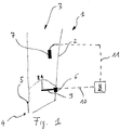
- an inlet arrangement 1 is shown schematically.
- the inlet arrangement 1 comprises a storage container 2 with a regrind inlet 3 and a regrind outlet 4.
- a dosing device 5, which is designed as a throttle valve, is also arranged on the regrind outlet 4.
- a gap width of the regrind outlet 4 can be changed by pivoting the throttle valve.
- a force transducer 6 is arranged on the storage container 2 and comprises a boom 9 which projects into the storage container 2 and can be designed, for example, as a bending beam.
- a regrind cone is formed, which is shown schematically by the dotted line.
- the control unit 8 which is connected to the force transducer 6 (shown schematically by the broken line 10), thus recognizes that a first fill level A has been reached in the storage container.
- the gradient of the fill level in the storage container 2 is recognized by the control unit 8 by an increase in the weight F determined by the force transducer 6.
- the control unit 8 can thus via a preliminary characteristic fill level curve K2, which in the Figure 2 is shown in dashed lines, carry out a preliminary level determination.
- a signal is sent to the control unit 8 via the connection 11 (also shown schematically by the dashed line), which signals the reaching of a level corresponding to a level B.
- the control unit 8 can thus use the first fill level A and the fill level B to determine a characteristic fill level curve K, which is shown schematically in FIG.
- the fill level curve K (and analogously the provisional fill level curve K2) relates a measured weight force F (x-axis) to a fill level FS (y-axis). From the Figure 2 is recognizable that with the level curve K for each weight force F determined by the force transducer 6, a level FS of the storage container 2 can be determined by the control unit 8, which level FS is more precise than a level which can only be determined with the aid of the preliminary level curve K2, the level curve K has been calibrated by using the level B level. A manual comparison of the actual level with the actual fill level of the storage container 2 can thus be omitted.
Landscapes
- Physics & Mathematics (AREA)
- Fluid Mechanics (AREA)
- General Physics & Mathematics (AREA)
- Engineering & Computer Science (AREA)
- Food Science & Technology (AREA)
- Crushing And Grinding (AREA)
- Weight Measurement For Supplying Or Discharging Of Specified Amounts Of Material (AREA)
- Filling Or Emptying Of Bunkers, Hoppers, And Tanks (AREA)
Abstract
Description
- Die Erfindung betrifft eine Einlaufanordnung für einen Walzenstuhl, eine Kontrolleinheit für eine Einlaufanordnung sowie einen Walzenstuhl mit einer erfindungsgemässen Einlaufanordnung. Die Erfindung betrifft ferner ein Verfahren zur Mahlgutfüllstandermittlung eines Vorratsbehälters eines Walzenstuhls.
- Bei Walzenstühlen aus dem Stand der Technik wird das Mahlgut vor der jeweiligen Mahlpassage einem Vorratsbehälter, z.B. durch Gravitation, zugeführt und dort aufgestaut. Das Mahlgut wird dann mit Hilfe einer Austragsvorrichtung, z.B. einer Speisewalze, dosiert und in den Mahlspalt befördert.
- Am Beginn des Mahlvorganges wird zuerst die Füllhöhe des Vorratsbehälters manuell, z.B. von einem Operator, als Soll-Niveau vorgegeben. Dabei ist zu berücksichtigen, dass zum einen genügend freies Puffervolumen zur Verfügung steht (Niveau möglichst tief), aber zum anderen das Mahlgut über die gesamte Länge der Walzen dosiert werden kann (Niveau möglichst hoch).
- Mit einer Messvorrichtung (zum Beispiel Kraftaufnehmer) wird beim Betreiben eine Abweichung des Ist-Niveaus zum Soll-Niveau detektiert. Eine Regelvorrichtung stellt sicher, dass der Austrag so angepasst wird, dass das Ist-Niveau möglichst dem Soll-Niveau entspricht. Kraftaufnehmer haben den Nachteil, dass der Füllstand des Mahlguts nicht direkt, sondern indirekt gemessen wird und somit eine Kalibrierung vorgenommen werden muss, welche stark von den Mahlguteigenschaften, insbesondere von der Mahlgutdichte, abhängt.
- Nachteilig bei solchen Messanordnungen ist, dass das von der Messvorrichtung gemessene Ist-Niveau unter Umständen nicht mit dem tatsächlichen Füllstand des Vorratsbehälters übereinstimmt. Der Operator muss somit stets manuell den tatsächlichen Füllstand überprüfen und eine Korrektur des ermittelten Ist-Niveau vornehmen.
- Es ist daher Aufgabe der vorliegenden Erfindung eine Einlaufanordnung für einen Walzenstuhl, eine Kontrolleinheit für eine Einlaufanordnung, einen Walzenstuhl sowie ein Verfahren zur Füllstandermittlung eines Vorratsbehälters anzugeben, welche die Nachteile des Bekannten vermeiden und insbesondere eine einfache, kostengünstige und automatische Füllstandermittlung des Vorratsbehälters ermöglichen.
- Die Aufgabe wird von einer Einlaufanordnung, einer Kontrolleinheit, einem Walzenstuhl und einem Verfahren mit den Merkmalen der unabhängigen Ansprüche gelöst.
- Es ist an dieser Stelle zu vermerken, dass im Sinne der vorliegenden Erfindung als Walzenstuhl eine Walzenanordnung gemeint wird, welche nicht nur in der Müllerei sondern auch bei anderen Lebensmitteln und Futtermitteln Anwendung finden kann.
- Die Einlaufanordnung umfasst einen Vorratsbehälter mit wenigstens einem Mahlguteinlass und wenigstens einem Mahlgutauslass.
- Die Einlaufanordnung umfasst ferner wenigstens eine am Vorratsbehälter angeordnete Dosiervorrichtung zum Dosieren von Mahlgut in einen Mahlspalt des Walzenstuhls durch den Mahlgutauslass. Die Dosiervorrichtung kann einfach als Spalt ausgebildet sein, wobei die Austragsmenge ggf. durch Änderung einer Spaltbreite, z.b. mit Hilfe einer Drosselklappe, einstellbar sein kann. Die Dosiervorrichtung kann ferner weitere Elemente umfassen, welche beispielsweise die Verteilung von Mahlgut im Vorratsbehälter unterstützen. Diese können beispielsweise eine Fördereinrichtung wie eine Paddel- oder Schneckenwelle umfassen. Auch kann die Dosiervorrichtung eine Speisewalze umfassen, welche zum Fördern vom Mahlgut vom Mahlgutauslass zum Mahlspalt des Walzenstuhls ausgebildet ist.
- Die Dosiervorrichtung kann entweder dem Vorratsbehälter nachgeschaltet sein, d.h. zwischen Mahlspalt und Vorratsbehälter angeordnet sein. Alternativ oder zusätzlich kann vorgesehen sein, dass die Dosiervorrichtung dem Vorratsbehälter vorgeschaltet ist, so dass die Mahlgutmenge, welche in den Vorratsbehälter gefördert wird, dosiert werden kann.
- Am Vorratsbehälter ist ein Kraftaufnehmer zur Bestimmung einer durch das Mahlgut ausgeübten Gewichtskraft angeordnet.
- Am Vorratsbehälter ist ferner ein Niveausensor zur Ermittlung des Erreichens eines Mahlgut-Niveaus angeordnet.
- Der Niveausensor liefert somit einen Wahrheitswert darüber, ob der Füllstand im Vorratsbehälter das Mahlgut-Niveau erreicht hat und ggf. dieses übersteigt oder nicht.
- Kraftaufnehmer und/oder Niveausensor können dabei ausserhalb oder innerhalb des Vorratsbehälters angeordnet sein. Beispielsweise kann der Vorratsbehälter mit einem Kraftaufnehmer verbunden sein, beispielsweise an einem Kraftaufnehmer aufgehängt oder auf einem Kraftaufnehmer gelagert sein. Erfindungsgemäss muss lediglich eine durch das Mahlgut ausgeübte Gewichtskraft im Vorratsbehälter sowie das Erreichen eines Mahlgut-Niveaus ermittelbar sein.
- Bevorzugt ist der Niveausensor im Vorratsbehälter, besonders bevorzugt in der oberen Hälfte des Vorratsbehälter, angeordnet.
- Bevorzugt ist der Kraftaufnehmer im Vorratsbehälter, besonders bevorzugt in einem unteren Bereich des Vorratsbehälters, angeordnet.
- Dies bedeutet, dass der Kraftaufnehmer derart angeordnet ist, dass bei einem niedrigen Füllstand des Vorratsbehälters eine Gewichtskraft ermittelt werden kann und, dass das Mahlgut den Niveausensor insbesondere erst erreicht, wenn der Vorratsbehälter zumindest zur Hälfte seines Fassungsvermögens befüllt worden ist.
- Die Einlaufanordnung umfasst ferner eine Kontrolleinheit, welche mit dem Kraftaufnehmer und dem Niveausensor verbunden oder verbindbar ist.
- Die Kontrolleinheit kann dabei eine dedizierte Kontrolleinheit der Einlaufanordnung sein, welche mit einer übergeordneten Kontrolleinheit, beispielsweise eines Walzenstuhls, verbunden wird. Dies ist insbesondere vorteilhaft, wenn die Einlaufanordnung zum Nachrüsten von bereits bestehenden Walzenstühlen gedacht ist. Alternativ dazu kann die Kontrolleinheit in einer übergeordneten Kontrolleinheit, beispielweise in der Kontrolleinheit eines Walzenstuhls oder in einer Anlagesteuerung, implementiert sein. Erfindungsgemäss ist die Kontrolleinheit dazu ausgebildet, aus der vom Kraftaufnehmer ermittelten Gewichtskraft einen ersten Füllstand des Vorratsbehälters zu ermitteln.
- Die Kontrolleinheit ist ferner dazu ausgebildet ist, eine charakteristische Füllstandkurve basierend auf dem ermittelten ersten Füllstand und dem vom Niveausensor ermittelten Füllstand-Niveau zu ermitteln.
- Bei dem ersten Füllstand handelt es sich bevorzugt um ein vorbestimmtes Füllstand-Niveau, welches der Anordnungshöhe des Kraftaufnehmers entspricht.
- Wie eingangs erwähnt ist der mit Hilfe des Kraftaufnehmers ermittelte Füllstand von vielen Faktoren, insbesondere von einer Mahlgutdichte, abhängig.
- Durch die Kontrolleinheit kann somit zunächst eine erste Aussage über den Füllstand des Vorratsbehälters getroffen werden, da eine Ermittlung von einer Gewichtskraft bedeutet, dass Mahlgut im Vorratsbehälter vorhanden ist und, falls der Kraftaufnehmer im Vorratsbehälter angeordnet ist, dass der Kraftaufnehmer mit Mahlgut beaufschlagt ist.
- Alternativ kann, da die ermittelte Gewichtskraft mit einem Füllstand korreliert, jeder beliebiger Füllstand herangezogen werden und bsp. über eine vorläufige Füllstandkurve und die Gewichtskraft-Füllstand-Korrelation ein vorläufiger ersten Füllstand ermittelt werden kann.
- Die vorläufige Füllstandkurve kann dabei lediglich mit der gemessenen Gewichtskraft ermittelt werden. Alternativ kann vorgesehen werden, dass der Operator Parameter betreffend das Mahlgut wie z.B. Mahlgrad des Mahlgutes, Walzenspaltbreite der vorgeschalteten Passage usw. eingeben kann, welche zur Ermittlung der vorläufigen Füllstandkurve herangezogen werden.
- Mit dem Niveausensor wird zusätzlich ermittelt, ob das Mahlgut einen bestimmten Füllstand-Niveau erreicht hat oder nicht.
- Darauf basierend kann die Kontrolleinheit auf einfache Art und Weise, bevorzugt durch Interpolation und/oder Extrapolation, eine charakteristische Füllstandkurve mithilfe des erreichten Füllstand-Niveaus und des ersten Füllstandes ermitteln.
- Bei der charakteristischen Füllstandkurve wird jeweils ein Gewichtskraftwert einem Füllstandwert zugeordnet.
- Somit kann der manuelle Abgleich zwischen Ist-Niveau und dem tatsächlichen Füllstand entfallen, da dieser nun durch die Kontrolleinheit durchgeführt wird.
- Die charakteristische Füllstandkurve wird bevorzugt beim Erreichen des Füllstand-Niveaus ermittelt. Besonders bevorzugt wird die charakteristische Füllstandkurve auch für Füllstände ermittelt, welche höher als das Füllstand-Niveau sind.
- Insbesondere kann die Kontrolleinheit derart ausgebildet sein, dass eine charakteristische Füllstandkurve bei jedem Erreichen des Füllstand-Niveaus neu ermittelt wird. Bei einer Abnahme des Füllstandes unterhalb des Füllstand-Niveaus wird die charakteristische Füllstandkurve weiterhin verwendet, wobei bei einer Zunahme des Füllstandes und bei erneutem Erreichen des Füllstand-Niveaus eine neue charakteristische Kurve ermittelt wird. Zudem kann, alternativ oder zusätzlich, vorgesehen sein, dass die charakteristische Füllstandkurve auch neu ermittelt wird, wenn der Füllstand unterhalb des Füllstand-Niveaus sinkt. Wenn der Füllstand abnimmt kann der Füllstandsensor zur Ermittlung eines Unterschreitens des Füllstand-Niveaus und somit zur Ermittlung der charakteristischen Füllstandkurve verwendet werden.
- In diesem Sinne wird gemäss der vorliegenden Erfindung unter "Erreichen eines Füllstand-Niveaus" das Erreichen des Füllstand-Niveaus bei Zunahme des Füllstandes und/oder das Unterschreiten des Füllstand-Niveau bei Abnahme des Füllstanden verstanden.
- Bevorzugt ist die Kontrolleinheit ferner dazu ausgebildet, nach der Ermittlung der charakteristischen Füllstandkurve, einen zweiten Füllstand basierend auf einer ermittelten Gewichtskraft und der charakteristischen Füllstandkurve zu ermitteln.
- Dadurch kann die Genauigkeit der Füllstandermittlung verbessert werden, da anhand der charakteristischen Füllstandkurve jeder Gewichtskraftwert einem Füllstandwert zugeordnet ist.
- Bevorzugt beträgt ein vertikaler Abstand zwischen dem Kraftaufnehmer und dem Niveausensor zwischen 20 und 80 cm, besonders bevorzugt zwischen 40 und 60 cm.
- Bevorzugt ist der Niveausensor als kapazitiver Sensor ausgebildet.
- Ein kapazitiver Sensor stellt eine besonders einfache, robuste und kostengünstige Möglichkeit zur Ermittlung des Füllstand-Niveaus dar.
- Die Erfindung betrifft ferner eine Kontrolleinheit für eine Einlaufanordnung eines Walzenstuhls. Sämtliche, oben beschriebene Vorteile und Weiterbildungen der Einlaufanordnung sind somit auch für eine erfindungsgemässe Kontrolleinheit entsprechend anwendbar.
- Die Kontrolleinheit ist dabei mit einem am Vorratsbehälter angeordneten Kraftaufnehmer zur Bestimmung einer durch das Mahlgut ausgeübten Gewichtskraft und mit einem am Vorratsbehälter angeordneten Niveausensor zur Ermittlung des Erreichens eines Mahlgut-Niveaus im Vorratsbehälter verbunden oder verbindbar.
- Die Kontrolleinheit ist ferner dazu ausgebildet, aus der von dem Kraftaufnehmer ermittelten Gewichtskraft einen ersten Füllstand des Vorratsbehälters und basierend auf dem ermittelten ersten Füllstand und dem vom Niveausensor ermittelten Füllstand-Niveau eine charakteristische Füllstandkurve zu ermitteln.
- Die Erfindung betrifft ferner einen Walzenstuhl mit einer erfindungsgemässen Einlaufanordnung. Sämtliche, oben beschriebene Vorteile und Weiterbildungen der Einlaufanordnung sind somit auch für einen erfindungsgemässen Walzenstuhl entsprechend anwendbar.
- Der Walzenstuhl umfasst wenigstens zwei Walzen, die einen Walzenspalt zum Mahlen von Mahlgut definieren, wobei der Walzenspalt mit Mahlgut aus dem Mahlgutauslass der Einlaufvorrichtung versorgt wird.
- Die Erfindung betrifft ferner ein Verfahren zur Füllstandermittlung eines Vorratsbehälters für Mahlgut eines Walzenstuhls. Sämtliche, oben beschriebene Vorteile und Weiterbildungen der Einlaufanordnung, der Kontrolleinheit und des Walzenstuhls sind somit auch für ein erfindungsgemässes Verfahren entsprechend anwendbar.
- Ein Vorratsbehälter umfasst dabei wenigstens einen Mahlguteinlass, wenigstens einen Mahlgutauslass und wenigstens eine Dosiervorrichtung zum Dosieren von Mahlgut in einen Mahlspalt des Walzenstuhls durch den Mahlgutauslass.
- Das erfindungsgemässe Verfahren umfasst die folgenden Schritte:
Zunächst wird eine durch das Mahlgut ausgeübte Gewichtskraft mit einem am Vorratsbehälter angeordneten Kraftaufnehmer ermittelt. - Aus der von dem Kraftaufnehmer ermittelten Gewichtskraft wird dann ein erster Füllstand des Vorratsbehälters ermittelt.
- Mit einem am Vorratsbehälter angeordneten Niveausensor wird das Erreichen eines Mahlgut-Niveaus im Vorratsbehälter ermittelt.
- Anschliessend wird eine charakteristische Füllstandkurve basierend auf dem ermittelten ersten Füllstand und dem vom Niveausensor ermittelten Fullstand-Niveau ermittelt.
- Wie oben bereits erwähnt kann somit mit einer einfachen Sensoranordnung das erfindungsgemässe Verfahren durchgeführt werden. Die vom Kraftaufnehmer ermittelte Gewichtskraft korreliert mit einem Füllstand des Vorratsbehälters. Über diese Korrelation kann somit ein Füllstand ermittelt werden.
- Mit dem Niveausensor wird zusätzlich ermittelt, ob das Mahlgut einen bestimmten Füllstand-Niveau erreicht hat oder nicht. Darauf basierend kann auf einfache Art und Weise eine charakteristische Füllstandkurve ermittelt werden, indem eine Füllstandkurve mithilfe des erreichten Füllstand-Niveaus und des ersten Füllstand, bevorzugt durch Interpolation und/oder Extrapolation, ermittelt wird.
- Die Füllstandkurve wird dann zur Ermittlung eines zweiten Füllstandes des Vorratsbehälters mit einer vom Kraftaufnehmer ermittelten Gewichtskraft verwendet.
- Somit kann der manuelle Abgleich zwischen Ist-Niveau und dem tatsächlichen Füllstand entfallen, da dieser nun durch die Kontrolleinheit durchgeführt wird.
- Die Erfindung wird nachfolgend anhand eines bevorzugten Ausführungsbeispiels in Verbindung mit den Figuren besser beschrieben. Es zeigen:
- Fig. 1
- eine schematische Schnittansicht der erfindungsgemässen Einlaufanordnung; und
- Fig. 2
- eine schematische Darstellung einer charakteristischen Füllstandkurve.
- In der
Figur 1 ist schematisch eine Einlaufanordnung 1 gezeigt. Die Einlaufanordnung 1 umfasst einen Vorratsbehälter 2 mit einem Mahlguteinlass 3 und einem Mahlgutauslass 4. Am Mahlgutauslass 4 ist ferner eine Dosiervorrichtung 5 angeordnet, welche als Drosselklappe ausgebildet ist. Durch Schwenken der Drosselklappe kann eine Spaltweite des Mahlgutauslasses 4 verändert werden. Am Vorratsbehälter 2 ist ein Kraftaufnehmer 6 angeordnet, welcher einen Ausleger 9 umfasst, der in den Vorratsbehälter 2 hineinragt und beispielsweise als Biegebalken ausgebildet sein kann. - Beim Befüllen des Vorratsbehälters 2 mit Mahlgut wird ein Mahlgutkegel gebildet, welcher schematisch durch die gepunktete Linie dargestellt ist. Sobald der Mahlgutkegel den Ausleger 9 erreicht hat, wird dieser mit einer Gewichtskraft FG belastet. Die Kontrolleinheit 8, welche mit dem Kraftaufnehmer 6 verbunden ist (schematisch durch die gestrichelte Linie 10 dargestellt), erkennt somit, dass ein erster Füllstand A im Vorratsbehälter erreicht worden ist.
- Beim weiteren Befüllen des Vorratsbehälters 2 steigt der Mahlgutkegel uns somit der Füllstand im Vorratsbehälter. Die Steigung des Füllstandes im Vorratsbehälter 2 wird von der Kontrolleinheit 8 durch eine Zunahme der von Kraftaufnehmer 6 ermittelten Gewichtskraft F erkannt. Die Kontrolleinheit 8 kann somit über eine vorläufige charakteristische Füllstandkurve K2, welche in der
Figur 2 gestrichelt dargestellt ist, eine vorläufige Füllstandermittlung durchführen. - Wenn der Mahlgutkegel den Niveausensor 7 erreicht hat, wird über die Verbindung 11 (ebenfalls schematisch durch die gestrichelte Linie dargestellt) der Kontrolleinheit 8 ein Signal übermittelt, welches das Erreichen eines Füllstand-Niveaus, das einem Füllstand B entspricht, signalisiert. Die Kontrolleinheit 8 kann somit mit dem ersten Füllstand A und dem Füllstand-Niveau B eine charakteristische Füllstandkurve K ermitteln, welche in der Figur 2 schematisch gezeigt ist.
- Die Füllstandkurve K (und analog die vorläufige Füllstandkurve K2) setzt eine gemessene Gewichtskraft F (x-Achse) mit einem Füllstand FS (y-Achse) in Relation. Aus der
Figur 2 ist erkennbar, dass mit der Füllstandkurve K für jede vom Kraftaufnehmer 6 ermittelte Gewichtskraft F ein Füllstand FS des Vorratsbehälters 2 von der Kontrolleinheit 8 bestimmt werden kann, welcher Füllstand FS genauer ist als ein Füllstand, welcher lediglich mit Hilfe der vorläufigen Füllstandkurve K2 bestimmbar ist, das die Füllstandkurve K durch Heranziehung des Füllstand-Niveaus B kalibriert worden ist. Ein manueller Abgleich des Ist-Niveaus mit dem tatsächlichen Füllstand des Vorratsbehälters 2 kann somit entfallen.
Claims (13)
- Einlaufanordnung (1) für einen Walzenstuhl umfassend:- einen Vorratsbehälter (2) mit wenigstens einem Mahlguteinlass (3) und wenigstens einem Mahlgutauslass (4),- wenigstens eine im Vorratsbehälter (2) angeordnete Dosiervorrichtung (5) zum Dosieren von Mahlgut in einen Mahlspalt des Walzenstuhls durch den Mahlgutauslass (4),- einen am Vorratsbehälter (2) angeordneten Kraftaufnehmer (6) zur Bestimmung einer durch das Mahlgut ausgeübten Gewichtskraft (FG),- einen am Vorratsbehälter (2) angeordneten Niveausensor (7) zur Ermittlung des Erreichens eines Mahlgut-Niveaus (B) im Vorratsbehälter (2), und- eine Kontrolleinheit (8), welche mit dem Kraftaufnehmer (6) und dem Niveausensor (7) verbunden oder verbindbar ist,dadurch gekennzeichnet, dass
die Kontrolleinheit (8) dazu ausgebildet ist, aus der von dem Kraftaufnehmer (6) ermittelten Gewichtskraft (FG) einen ersten Füllstand (A) des Vorratsbehälters (2) zu ermitteln, wobei die Kontrolleinheit (8) ferner dazu ausgebildet ist, eine charakteristische Füllstandkurve (K) basierend auf dem ermittelten ersten Füllstand (A) und dem vom Niveausensor (7) ermittelten Füllstand-Niveau (B) zu ermitteln. - Einlaufanordnung (1) nach Anspruch 1, dadurch gekennzeichnet, dass die charakteristische Füllstandkurve (K) beim Erreichen des Füllstand-Niveaus (B) ermittelt wird.
- Einlaufanordnung (1) nach einem der vorhergehenden Ansprüche, dadurch gekennzeichnet, dass die Kontrolleinheit (8) ferner dazu ausgebildet ist, nach der Ermittlung der charakteristischen Füllstandkurve (K), einen zweiten Füllstand basierend auf einer ermittelten Gewichtskraft (F) und der charakteristischen Füllstandkurve (K) zu ermitteln.
- Einlaufanordnung (1) nach einem der vorhergehenden Ansprüche, dadurch gekennzeichnet, dass ein vertikaler Abstand zwischen dem Kraftaufnehmer (6) und dem Niveausensor (7) zwischen 20 und 80 cm beträgt.
- Einlaufanordnung (1) nach einem der vorhergehenden Ansprüche, dadurch gekennzeichnet, dass der Niveausensor (7) ein kapazitiver Sensor ist.
- Einlaufanordnung (1) nach einem der vorhergehenden Ansprüche, dadurch gekennzeichnet, dass die charakteristische Füllstandkurve (K) durch Interpolation und/oder Extrapolation ermittelt wird.
- Einlaufanordnung (1) nach einem der vorhergehenden Ansprüche, dadurch gekennzeichnet, dass der Niveausensor (7) im Vorratsbehälter (2) angeordnet ist.
- Einlaufanordnung (1) nach einem der vorhergehenden Ansprüche, dadurch gekennzeichnet, dass der Kraftaufnehmer (6) im Vorratsbehälter (2) angeordnet ist.
- Einlaufanordnung (1) nach Anspruch 8, dadurch gekennzeichnet, dass der Kraftaufnehmer (6) in einem unteren Bereich des Vorratsbehälters (2) angeordnet ist.
- Kontrolleinheit (8) für eine Einlaufanordnung (1) mit einem Vorratsbehälter (2) eines Walzenstuhls, insbesondere eine Einlaufanordnung (1) nach einem der vorhergehenden Patentansprüche, dadurch gekennzeichnet, dass die Kontrolleinheit (8) mit einem am Vorratsbehälter (2) angeordneten Kraftaufnehmer (6) zur Bestimmung einer durch das Mahlgut ausgeübten Gewichtskraft (FG) und mit einem am Vorratsbehälter (2) angeordneten Niveausensor (7) zur Ermittlung des Erreichens eines Mahlgut-Niveaus (B) im Vorratsbehälter (2) verbunden oder verbindbar ist, wobei die Kontrolleinheit (8) ferner dazu ausgebildet ist, aus der von dem Kraftaufnehmer (6) ermittelten Gewichtskraft (FG) einen ersten Füllstand (A) des Vorratsbehälters (2) und basierend auf dem ermittelten ersten Füllstand (A) und dem vom Niveausensor (7) ermittelten Füllstand-Niveau (B) eine charakteristische Füllstandkurve (K) zu ermitteln.
- Walzenstuhl (14) mit wenigstens zwei Walzen, welche einen Walzenspalt definieren, dadurch gekennzeichnet, dass der Walzenstuhl ferner eine Einlaufanordnung (1) nach einem der Ansprüche 1 bis 9 umfasst.
- Verfahren zur Mahlgutfüllstandermittlung eines Vorratsbehälter (2) für Mahlgut eines Walzenstuhls, wobei der Vorratsbehälter wenigstens einen Mahlguteinlass (3), wenigstens einen Mahlgutauslass (4) und wenigstens eine Dosiervorrichtung (5) zum Dosieren von Mahlgut in einen Mahlspalt des Walzenstuhls durch den Mahlgutauslass (4) umfasst, umfassend die folgenden Schritte:- Bestimmen einer durch das Mahlgut ausgeübten Gewichtskraft (FG) mit einem im Vorratsbehälter (2) angeordneten Kraftaufnehmer (6),- Ermitteln eines ersten Füllstands (A) des Vorratsbehälter (2) aus der von dem Kraftaufnehmer (6) ermittelten Gewichtskraft,- Ermitteln des Erreichens eines Mahlgut-Niveaus (B) im Vorratsbehälter (2) mit einem im Vorratsbehälter (2) angeordneten Niveausensor (7),- Ermitteln einer charakteristischen Füllstandkurve (K) basierend auf dem ermittelten ersten Füllstand (A) und dem vom Niveausensor (7) ermittelten Fullstand-Niveau (B).
- Verfahren nach Anspruch 12, dadurch gekennzeichnet, dass die charakteristische Füllstandkurve (K) durch Interpolation und/oder Extrapolation ermittelt wird.
Priority Applications (12)
| Application Number | Priority Date | Filing Date | Title |
|---|---|---|---|
| ES18186666T ES2901827T3 (es) | 2018-07-31 | 2018-07-31 | Dispositivo de entrada para un molino de cilindros, molino de cilindros con un dispositivo de entrada de este tipo, procedimiento para la determinación del nivel de relleno de material de molienda de un depósito de almacenamiento de un molino de cilindros |
| EP18186666.6A EP3605034B1 (de) | 2018-07-31 | 2018-07-31 | Einlaufanordnung für einen walzenstuhl, walzenstuhl mit einer solchen einlaufanordnung, verfahren zur mahlgutfüllstandermittlung eines vorratsbehälters eines walzenstuhls |
| JP2021505354A JP7031058B2 (ja) | 2018-07-31 | 2019-07-31 | ローラミルのための取込み装置、このような取込み装置を備えたローラミルならびにローラミルの蓄え容器の粉砕物充填状態を求めるための方法 |
| AU2019313596A AU2019313596B2 (en) | 2018-07-31 | 2019-07-31 | Intake arrangement for a roller mill, roller mill having such an intake arrangement and method for determining the ground material fill level of a storage container of a roller mill |
| MX2021001202A MX2021001202A (es) | 2018-07-31 | 2019-07-31 | Arreglo de entrada para un molino de rodillos, molino de rodillos con dicho arreglo de entrada y metodo para determinar el nivel de material de molienda en un contenedor de almacenamiento de un molino de rodillos. |
| RU2021103659A RU2764123C1 (ru) | 2018-07-31 | 2019-07-31 | Входное устройство для вальцового станка, вальцовый станок с таким входным устройством и способ определения уровня наполнения размалываемым материалом бункера вальцового станка |
| CA3106173A CA3106173C (en) | 2018-07-31 | 2019-07-31 | Inlet arrangement for a roller mill, roller mill with such an inlet arrangement and method for determining the level of milling material in a storage container of a roller mill |
| US17/263,982 US11860020B2 (en) | 2018-07-31 | 2019-07-31 | Intake arrangement for a roller mill, roller mill having such an intake arrangement and method for determining the ground material fill level of a storage container of a roller mill |
| KR1020217005606A KR102488155B1 (ko) | 2018-07-31 | 2019-07-31 | 롤러 밀용 입구 장치, 이러한 입구 장치를 가지는 롤러 밀 및 롤러 밀의 저장 용기에서 분쇄 재료의 레벨을 결정하기 위한 방법 |
| CN201980049361.6A CN112585438A (zh) | 2018-07-31 | 2019-07-31 | 辊磨机的导入装置、具有导入装置的辊磨机以及用于确定辊磨机的储料箱中的碾磨物料料位的方法 |
| BR112021000659-1A BR112021000659A2 (pt) | 2018-07-31 | 2019-07-31 | Disposição de entrada para um moinho de rolos, moinho de rolos com tal disposição de entrada e método para determinar o nível de material de moagem em um recipiente de armazenagem de um moinho de rolos |
| PCT/EP2019/070644 WO2020025681A1 (de) | 2018-07-31 | 2019-07-31 | Einlaufanordnung für einen walzenstuhl, walzenstuhl mit einer solchen einlaufanordnung sowie verfahren zur mahlgutfüllstandermittlung eines vorratsbehälters eines walzenstuhls |
Applications Claiming Priority (1)
| Application Number | Priority Date | Filing Date | Title |
|---|---|---|---|
| EP18186666.6A EP3605034B1 (de) | 2018-07-31 | 2018-07-31 | Einlaufanordnung für einen walzenstuhl, walzenstuhl mit einer solchen einlaufanordnung, verfahren zur mahlgutfüllstandermittlung eines vorratsbehälters eines walzenstuhls |
Publications (2)
| Publication Number | Publication Date |
|---|---|
| EP3605034A1 true EP3605034A1 (de) | 2020-02-05 |
| EP3605034B1 EP3605034B1 (de) | 2021-09-22 |
Family
ID=63113390
Family Applications (1)
| Application Number | Title | Priority Date | Filing Date |
|---|---|---|---|
| EP18186666.6A Active EP3605034B1 (de) | 2018-07-31 | 2018-07-31 | Einlaufanordnung für einen walzenstuhl, walzenstuhl mit einer solchen einlaufanordnung, verfahren zur mahlgutfüllstandermittlung eines vorratsbehälters eines walzenstuhls |
Country Status (12)
| Country | Link |
|---|---|
| US (1) | US11860020B2 (de) |
| EP (1) | EP3605034B1 (de) |
| JP (1) | JP7031058B2 (de) |
| KR (1) | KR102488155B1 (de) |
| CN (1) | CN112585438A (de) |
| AU (1) | AU2019313596B2 (de) |
| BR (1) | BR112021000659A2 (de) |
| CA (1) | CA3106173C (de) |
| ES (1) | ES2901827T3 (de) |
| MX (1) | MX2021001202A (de) |
| RU (1) | RU2764123C1 (de) |
| WO (1) | WO2020025681A1 (de) |
Cited By (1)
| Publication number | Priority date | Publication date | Assignee | Title |
|---|---|---|---|---|
| WO2023198735A1 (de) | 2022-04-14 | 2023-10-19 | Swisca Ag | Dosier- und/oder wiegevorrichtung für nahrungsmittel |
Families Citing this family (2)
| Publication number | Priority date | Publication date | Assignee | Title |
|---|---|---|---|---|
| CA3221170A1 (en) | 2021-07-12 | 2023-01-19 | Buhler Ag | Feed level control system and method |
| CN115284079B (zh) * | 2022-09-30 | 2023-01-03 | 中国科学院长春光学精密机械与物理研究所 | 磁流变抛光标定方法 |
Citations (2)
| Publication number | Priority date | Publication date | Assignee | Title |
|---|---|---|---|---|
| US5433391A (en) * | 1991-10-11 | 1995-07-18 | Satake Uk Limited | Cereal milling machine |
| US20160067713A1 (en) * | 2013-04-23 | 2016-03-10 | Satake Corporation | Stock level detector for roll machine for milling |
Family Cites Families (21)
| Publication number | Priority date | Publication date | Assignee | Title |
|---|---|---|---|---|
| US543391A (en) * | 1895-07-23 | Slack-adjuster | ||
| US4169543A (en) * | 1977-10-20 | 1979-10-02 | Keystone International, Inc. | Amplitude responsive detector |
| IT1160480B (it) * | 1983-02-25 | 1987-03-11 | Sangati Spa | Dispositivo per la regolazione automatica della alimentazione del prodotto in un laminatoio di macinazione per cereali |
| FI94676C (fi) * | 1993-11-16 | 1995-10-10 | Aspo Systems Oy | Menetelmä ja laitteisto nesteen mittauslaitteiston kalibroimiseksi |
| KR200159558Y1 (ko) * | 1997-05-29 | 1999-10-15 | 최병준 | 미곡의 중량계량과 수분측정용 호퍼 스케일 |
| DE19726551A1 (de) * | 1997-06-23 | 1998-12-24 | Buehler Ag | Speisesensorik |
| JP2003266614A (ja) * | 2002-03-15 | 2003-09-24 | Toyo Ink Mfg Co Ltd | 自動車部材成型加工用材料及び自動車部材 |
| JP4760052B2 (ja) * | 2005-02-24 | 2011-08-31 | ヤマハ株式会社 | 伝送制御装置およびサンプリング周波数変換装置 |
| CN200996852Y (zh) * | 2006-07-06 | 2007-12-26 | 张红岩 | 一种粉仓料位检测装置 |
| CN200989806Y (zh) * | 2006-11-06 | 2007-12-12 | 河南中原轧辊有限公司 | 磨粉机喂料传感装置 |
| US20090188641A1 (en) * | 2008-01-30 | 2009-07-30 | Andritz Inc. | Method and system for measuring and controlling digester or impregnation vessel chip level by measuring chip pressure |
| EP2540396A1 (de) * | 2011-06-30 | 2013-01-02 | Bühler AG | Verfahren und Vorrichtung für die Herstellung von Mehl und/oder Griess |
| CN202230393U (zh) * | 2011-09-09 | 2012-05-23 | 珠海裕嘉矿产品有限公司 | 一种自动料位控制装置 |
| RU2537099C1 (ru) * | 2013-05-14 | 2014-12-27 | Открытое акционерное общество "Союзцветметавтоматика" | Устройство для измерения весового расхода и весового дозирования жидких флотационных реагентов (весовой расходомер/дозатор жидкости) |
| CN203405260U (zh) * | 2013-07-01 | 2014-01-22 | 首钢京唐钢铁联合有限责任公司 | 用于高压辊磨料斗料位测量的装置 |
| CN203764316U (zh) * | 2014-01-10 | 2014-08-13 | 中信重工机械股份有限公司 | 一种高压辊磨机雷达料位检测装置 |
| CN203772360U (zh) * | 2014-01-10 | 2014-08-13 | 中信重工机械股份有限公司 | 一种可在恶劣环境下精确测量料位的料仓装置 |
| US9702753B2 (en) * | 2014-06-27 | 2017-07-11 | Deere & Company | Grain mass flow estimation |
| BR112017017833B1 (pt) * | 2015-02-23 | 2021-07-06 | Bühler AG | Moinho de cilindros, conjunto de aspiração e processo para recondicionamento de um moinho de cilindros |
| CN205333152U (zh) * | 2015-12-21 | 2016-06-22 | 上海云鱼智能科技有限公司 | 电磁波节点料位计 |
| CN206231915U (zh) * | 2016-12-05 | 2017-06-09 | 泰安中意重型工业设备有限公司 | 一种用于颗粒或块状物料料位检测装置 |
-
2018
- 2018-07-31 EP EP18186666.6A patent/EP3605034B1/de active Active
- 2018-07-31 ES ES18186666T patent/ES2901827T3/es active Active
-
2019
- 2019-07-31 BR BR112021000659-1A patent/BR112021000659A2/pt unknown
- 2019-07-31 KR KR1020217005606A patent/KR102488155B1/ko active IP Right Grant
- 2019-07-31 WO PCT/EP2019/070644 patent/WO2020025681A1/de active Application Filing
- 2019-07-31 CA CA3106173A patent/CA3106173C/en active Active
- 2019-07-31 AU AU2019313596A patent/AU2019313596B2/en active Active
- 2019-07-31 CN CN201980049361.6A patent/CN112585438A/zh active Pending
- 2019-07-31 US US17/263,982 patent/US11860020B2/en active Active
- 2019-07-31 MX MX2021001202A patent/MX2021001202A/es unknown
- 2019-07-31 RU RU2021103659A patent/RU2764123C1/ru active
- 2019-07-31 JP JP2021505354A patent/JP7031058B2/ja active Active
Patent Citations (2)
| Publication number | Priority date | Publication date | Assignee | Title |
|---|---|---|---|---|
| US5433391A (en) * | 1991-10-11 | 1995-07-18 | Satake Uk Limited | Cereal milling machine |
| US20160067713A1 (en) * | 2013-04-23 | 2016-03-10 | Satake Corporation | Stock level detector for roll machine for milling |
Cited By (2)
| Publication number | Priority date | Publication date | Assignee | Title |
|---|---|---|---|---|
| WO2023198735A1 (de) | 2022-04-14 | 2023-10-19 | Swisca Ag | Dosier- und/oder wiegevorrichtung für nahrungsmittel |
| CH719612A1 (de) * | 2022-04-14 | 2023-10-31 | Swisca Ag | Dosier- und/oder Wiegevorrichtung für Nahrungsmittel mit Füllstandsüberwachung. |
Also Published As
| Publication number | Publication date |
|---|---|
| US11860020B2 (en) | 2024-01-02 |
| AU2019313596B2 (en) | 2022-04-28 |
| KR20210034074A (ko) | 2021-03-29 |
| JP2021532367A (ja) | 2021-11-25 |
| BR112021000659A2 (pt) | 2021-04-13 |
| AU2019313596A1 (en) | 2021-02-04 |
| EP3605034B1 (de) | 2021-09-22 |
| US20210302217A1 (en) | 2021-09-30 |
| RU2764123C1 (ru) | 2022-01-13 |
| MX2021001202A (es) | 2021-04-12 |
| CA3106173A1 (en) | 2020-02-06 |
| CA3106173C (en) | 2023-10-03 |
| JP7031058B2 (ja) | 2022-03-07 |
| ES2901827T3 (es) | 2022-03-23 |
| KR102488155B1 (ko) | 2023-01-12 |
| WO2020025681A1 (de) | 2020-02-06 |
| CN112585438A (zh) | 2021-03-30 |
Similar Documents
| Publication | Publication Date | Title |
|---|---|---|
| EP3605034B1 (de) | Einlaufanordnung für einen walzenstuhl, walzenstuhl mit einer solchen einlaufanordnung, verfahren zur mahlgutfüllstandermittlung eines vorratsbehälters eines walzenstuhls | |
| EP2707138A2 (de) | Vorrichtung und verfahren zum zerkleinern von partikeln in einem fliessfähigen material | |
| DE3301958C2 (de) | ||
| DE112013002952B4 (de) | Misch- und Einstellverfahren für Formsand | |
| EP2372321A1 (de) | Verfahren und Vorrichtung zum Füllen von Zielbehältern | |
| DE3829623C2 (de) | ||
| EP2232207A1 (de) | Förderdosiervorrichtung | |
| DE19939042A1 (de) | Verfahren zur Bereitstellung eines zu dosierenden Materialgemischs und Ermittlung des Durchsatzes, und Anlage zur Durchführung des Verfahrens | |
| EP2159555A1 (de) | Verfahren und Vorrichtung zum Füllen von Zielbehältern | |
| DE102017207162A1 (de) | Vorrichtung zum Komprimieren eines Produkts | |
| DE102010009753B4 (de) | Vorrichtung und Verfahren zur Dosierregelung von Schüttgut | |
| EP3856645A1 (de) | Fülleinheit und verfahren zum befüllen von gebinden | |
| EP0485772B1 (de) | Mahlwerk | |
| EP2560761B2 (de) | Aufgabevorrichtung für eine hochdruckrollenpresse | |
| DE3601593C1 (de) | Verfahren und Vorrichtung zum Mahlen von Sprengstoffen | |
| WO2005005133A2 (de) | Verfahren und anlage zur automatisierten annahme und weiterverarbeitung von trauben | |
| DE2454238C2 (de) | Verfahren und Vorrichtung zum Absetzen oder Verdichten von Quark | |
| EP0121599A2 (de) | Verfahren und Vorrichtung zur pneumatischen Förderung von Feingut | |
| DE102018121966A1 (de) | Gravimetrische Dosiervorrichtung für Schüttgüter und Verfahren zum Betreiben einer derartigen Dosiervorrichtung | |
| EP3207805B1 (de) | Abfüllen von lebensmitteln mit festem und flüssigem anteil | |
| DE102014006001B4 (de) | Flüssigfütterungsanlage und Verfahren zur Flüssigfütterung | |
| DE102016120288A1 (de) | Sämaschine mit Füllstandsbestimmung | |
| DE4129898A1 (de) | Verfahren zum vermahlen von koernerfruechten sowie vorrichtung zur durchfuehrung des verfahrens | |
| DE19512098C1 (de) | Steuervorrichtung für einen Mehrphasenstrom sowie Verfahren zum Herstellen eines Naßmörtels | |
| DE102018119304A1 (de) | Behälter zur Durchleitung eines Aktivkohlepulver-Luft Gemischs |
Legal Events
| Date | Code | Title | Description |
|---|---|---|---|
| PUAI | Public reference made under article 153(3) epc to a published international application that has entered the european phase |
Free format text: ORIGINAL CODE: 0009012 |
|
| STAA | Information on the status of an ep patent application or granted ep patent |
Free format text: STATUS: THE APPLICATION HAS BEEN PUBLISHED |
|
| AK | Designated contracting states |
Kind code of ref document: A1 Designated state(s): AL AT BE BG CH CY CZ DE DK EE ES FI FR GB GR HR HU IE IS IT LI LT LU LV MC MK MT NL NO PL PT RO RS SE SI SK SM TR |
|
| AX | Request for extension of the european patent |
Extension state: BA ME |
|
| STAA | Information on the status of an ep patent application or granted ep patent |
Free format text: STATUS: REQUEST FOR EXAMINATION WAS MADE |
|
| 17P | Request for examination filed |
Effective date: 20200604 |
|
| RBV | Designated contracting states (corrected) |
Designated state(s): AL AT BE BG CH CY CZ DE DK EE ES FI FR GB GR HR HU IE IS IT LI LT LU LV MC MK MT NL NO PL PT RO RS SE SI SK SM TR |
|
| RIN1 | Information on inventor provided before grant (corrected) |
Inventor name: MARINOS, DIMITROS Inventor name: FISCHER, DANIEL Inventor name: RICKENBACH, DANIEL |
|
| GRAP | Despatch of communication of intention to grant a patent |
Free format text: ORIGINAL CODE: EPIDOSNIGR1 |
|
| STAA | Information on the status of an ep patent application or granted ep patent |
Free format text: STATUS: GRANT OF PATENT IS INTENDED |
|
| INTG | Intention to grant announced |
Effective date: 20210504 |
|
| GRAS | Grant fee paid |
Free format text: ORIGINAL CODE: EPIDOSNIGR3 |
|
| GRAA | (expected) grant |
Free format text: ORIGINAL CODE: 0009210 |
|
| STAA | Information on the status of an ep patent application or granted ep patent |
Free format text: STATUS: THE PATENT HAS BEEN GRANTED |
|
| AK | Designated contracting states |
Kind code of ref document: B1 Designated state(s): AL AT BE BG CH CY CZ DE DK EE ES FI FR GB GR HR HU IE IS IT LI LT LU LV MC MK MT NL NO PL PT RO RS SE SI SK SM TR |
|
| REG | Reference to a national code |
Ref country code: GB Ref legal event code: FG4D Free format text: NOT ENGLISH |
|
| REG | Reference to a national code |
Ref country code: DE Ref legal event code: R096 Ref document number: 502018007147 Country of ref document: DE |
|
| REG | Reference to a national code |
Ref country code: IE Ref legal event code: FG4D Free format text: LANGUAGE OF EP DOCUMENT: GERMAN |
|
| REG | Reference to a national code |
Ref country code: CH Ref legal event code: EP Ref country code: AT Ref legal event code: REF Ref document number: 1432679 Country of ref document: AT Kind code of ref document: T Effective date: 20211015 |
|
| REG | Reference to a national code |
Ref country code: LT Ref legal event code: MG9D |
|
| REG | Reference to a national code |
Ref country code: NL Ref legal event code: MP Effective date: 20210922 |
|
| PG25 | Lapsed in a contracting state [announced via postgrant information from national office to epo] |
Ref country code: NO Free format text: LAPSE BECAUSE OF FAILURE TO SUBMIT A TRANSLATION OF THE DESCRIPTION OR TO PAY THE FEE WITHIN THE PRESCRIBED TIME-LIMIT Effective date: 20211222 Ref country code: LT Free format text: LAPSE BECAUSE OF FAILURE TO SUBMIT A TRANSLATION OF THE DESCRIPTION OR TO PAY THE FEE WITHIN THE PRESCRIBED TIME-LIMIT Effective date: 20210922 Ref country code: BG Free format text: LAPSE BECAUSE OF FAILURE TO SUBMIT A TRANSLATION OF THE DESCRIPTION OR TO PAY THE FEE WITHIN THE PRESCRIBED TIME-LIMIT Effective date: 20211222 Ref country code: SE Free format text: LAPSE BECAUSE OF FAILURE TO SUBMIT A TRANSLATION OF THE DESCRIPTION OR TO PAY THE FEE WITHIN THE PRESCRIBED TIME-LIMIT Effective date: 20210922 Ref country code: RS Free format text: LAPSE BECAUSE OF FAILURE TO SUBMIT A TRANSLATION OF THE DESCRIPTION OR TO PAY THE FEE WITHIN THE PRESCRIBED TIME-LIMIT Effective date: 20210922 Ref country code: HR Free format text: LAPSE BECAUSE OF FAILURE TO SUBMIT A TRANSLATION OF THE DESCRIPTION OR TO PAY THE FEE WITHIN THE PRESCRIBED TIME-LIMIT Effective date: 20210922 Ref country code: FI Free format text: LAPSE BECAUSE OF FAILURE TO SUBMIT A TRANSLATION OF THE DESCRIPTION OR TO PAY THE FEE WITHIN THE PRESCRIBED TIME-LIMIT Effective date: 20210922 |
|
| PG25 | Lapsed in a contracting state [announced via postgrant information from national office to epo] |
Ref country code: LV Free format text: LAPSE BECAUSE OF FAILURE TO SUBMIT A TRANSLATION OF THE DESCRIPTION OR TO PAY THE FEE WITHIN THE PRESCRIBED TIME-LIMIT Effective date: 20210922 Ref country code: GR Free format text: LAPSE BECAUSE OF FAILURE TO SUBMIT A TRANSLATION OF THE DESCRIPTION OR TO PAY THE FEE WITHIN THE PRESCRIBED TIME-LIMIT Effective date: 20211223 |
|
| REG | Reference to a national code |
Ref country code: ES Ref legal event code: FG2A Ref document number: 2901827 Country of ref document: ES Kind code of ref document: T3 Effective date: 20220323 |
|
| PG25 | Lapsed in a contracting state [announced via postgrant information from national office to epo] |
Ref country code: IS Free format text: LAPSE BECAUSE OF FAILURE TO SUBMIT A TRANSLATION OF THE DESCRIPTION OR TO PAY THE FEE WITHIN THE PRESCRIBED TIME-LIMIT Effective date: 20220122 Ref country code: SK Free format text: LAPSE BECAUSE OF FAILURE TO SUBMIT A TRANSLATION OF THE DESCRIPTION OR TO PAY THE FEE WITHIN THE PRESCRIBED TIME-LIMIT Effective date: 20210922 Ref country code: RO Free format text: LAPSE BECAUSE OF FAILURE TO SUBMIT A TRANSLATION OF THE DESCRIPTION OR TO PAY THE FEE WITHIN THE PRESCRIBED TIME-LIMIT Effective date: 20210922 Ref country code: PT Free format text: LAPSE BECAUSE OF FAILURE TO SUBMIT A TRANSLATION OF THE DESCRIPTION OR TO PAY THE FEE WITHIN THE PRESCRIBED TIME-LIMIT Effective date: 20220124 Ref country code: PL Free format text: LAPSE BECAUSE OF FAILURE TO SUBMIT A TRANSLATION OF THE DESCRIPTION OR TO PAY THE FEE WITHIN THE PRESCRIBED TIME-LIMIT Effective date: 20210922 Ref country code: NL Free format text: LAPSE BECAUSE OF FAILURE TO SUBMIT A TRANSLATION OF THE DESCRIPTION OR TO PAY THE FEE WITHIN THE PRESCRIBED TIME-LIMIT Effective date: 20210922 Ref country code: EE Free format text: LAPSE BECAUSE OF FAILURE TO SUBMIT A TRANSLATION OF THE DESCRIPTION OR TO PAY THE FEE WITHIN THE PRESCRIBED TIME-LIMIT Effective date: 20210922 Ref country code: CZ Free format text: LAPSE BECAUSE OF FAILURE TO SUBMIT A TRANSLATION OF THE DESCRIPTION OR TO PAY THE FEE WITHIN THE PRESCRIBED TIME-LIMIT Effective date: 20210922 Ref country code: AL Free format text: LAPSE BECAUSE OF FAILURE TO SUBMIT A TRANSLATION OF THE DESCRIPTION OR TO PAY THE FEE WITHIN THE PRESCRIBED TIME-LIMIT Effective date: 20210922 |
|
| REG | Reference to a national code |
Ref country code: DE Ref legal event code: R097 Ref document number: 502018007147 Country of ref document: DE |
|
| PG25 | Lapsed in a contracting state [announced via postgrant information from national office to epo] |
Ref country code: DK Free format text: LAPSE BECAUSE OF FAILURE TO SUBMIT A TRANSLATION OF THE DESCRIPTION OR TO PAY THE FEE WITHIN THE PRESCRIBED TIME-LIMIT Effective date: 20210922 |
|
| PLBE | No opposition filed within time limit |
Free format text: ORIGINAL CODE: 0009261 |
|
| STAA | Information on the status of an ep patent application or granted ep patent |
Free format text: STATUS: NO OPPOSITION FILED WITHIN TIME LIMIT |
|
| 26N | No opposition filed |
Effective date: 20220623 |
|
| PG25 | Lapsed in a contracting state [announced via postgrant information from national office to epo] |
Ref country code: SI Free format text: LAPSE BECAUSE OF FAILURE TO SUBMIT A TRANSLATION OF THE DESCRIPTION OR TO PAY THE FEE WITHIN THE PRESCRIBED TIME-LIMIT Effective date: 20210922 |
|
| PG25 | Lapsed in a contracting state [announced via postgrant information from national office to epo] |
Ref country code: MC Free format text: LAPSE BECAUSE OF FAILURE TO SUBMIT A TRANSLATION OF THE DESCRIPTION OR TO PAY THE FEE WITHIN THE PRESCRIBED TIME-LIMIT Effective date: 20210922 |
|
| REG | Reference to a national code |
Ref country code: BE Ref legal event code: MM Effective date: 20220731 |
|
| PG25 | Lapsed in a contracting state [announced via postgrant information from national office to epo] |
Ref country code: LU Free format text: LAPSE BECAUSE OF NON-PAYMENT OF DUE FEES Effective date: 20220731 |
|
| PG25 | Lapsed in a contracting state [announced via postgrant information from national office to epo] |
Ref country code: BE Free format text: LAPSE BECAUSE OF NON-PAYMENT OF DUE FEES Effective date: 20220731 |
|
| P01 | Opt-out of the competence of the unified patent court (upc) registered |
Effective date: 20230523 |
|
| PG25 | Lapsed in a contracting state [announced via postgrant information from national office to epo] |
Ref country code: IE Free format text: LAPSE BECAUSE OF NON-PAYMENT OF DUE FEES Effective date: 20220731 |
|
| PGFP | Annual fee paid to national office [announced via postgrant information from national office to epo] |
Ref country code: TR Payment date: 20230727 Year of fee payment: 6 Ref country code: IT Payment date: 20230731 Year of fee payment: 6 Ref country code: GB Payment date: 20230724 Year of fee payment: 6 Ref country code: ES Payment date: 20230821 Year of fee payment: 6 Ref country code: CH Payment date: 20230801 Year of fee payment: 6 Ref country code: AT Payment date: 20230718 Year of fee payment: 6 |
|
| PGFP | Annual fee paid to national office [announced via postgrant information from national office to epo] |
Ref country code: FR Payment date: 20230724 Year of fee payment: 6 Ref country code: DE Payment date: 20230720 Year of fee payment: 6 |
|
| PG25 | Lapsed in a contracting state [announced via postgrant information from national office to epo] |
Ref country code: HU Free format text: LAPSE BECAUSE OF FAILURE TO SUBMIT A TRANSLATION OF THE DESCRIPTION OR TO PAY THE FEE WITHIN THE PRESCRIBED TIME-LIMIT; INVALID AB INITIO Effective date: 20180731 |
|
| PG25 | Lapsed in a contracting state [announced via postgrant information from national office to epo] |
Ref country code: SM Free format text: LAPSE BECAUSE OF FAILURE TO SUBMIT A TRANSLATION OF THE DESCRIPTION OR TO PAY THE FEE WITHIN THE PRESCRIBED TIME-LIMIT Effective date: 20210922 Ref country code: MK Free format text: LAPSE BECAUSE OF FAILURE TO SUBMIT A TRANSLATION OF THE DESCRIPTION OR TO PAY THE FEE WITHIN THE PRESCRIBED TIME-LIMIT Effective date: 20210922 Ref country code: CY Free format text: LAPSE BECAUSE OF FAILURE TO SUBMIT A TRANSLATION OF THE DESCRIPTION OR TO PAY THE FEE WITHIN THE PRESCRIBED TIME-LIMIT Effective date: 20210922 |