EP3604067A1 - Appareil de détermination de véhicule précédent et système de commande de véhicule - Google Patents
Appareil de détermination de véhicule précédent et système de commande de véhicule Download PDFInfo
- Publication number
- EP3604067A1 EP3604067A1 EP18772402.6A EP18772402A EP3604067A1 EP 3604067 A1 EP3604067 A1 EP 3604067A1 EP 18772402 A EP18772402 A EP 18772402A EP 3604067 A1 EP3604067 A1 EP 3604067A1
- Authority
- EP
- European Patent Office
- Prior art keywords
- vehicle
- host
- lane
- distance
- host vehicle
- Prior art date
- Legal status (The legal status is an assumption and is not a legal conclusion. Google has not performed a legal analysis and makes no representation as to the accuracy of the status listed.)
- Withdrawn
Links
- 238000006243 chemical reaction Methods 0.000 claims abstract description 31
- 238000001514 detection method Methods 0.000 claims abstract description 8
- 230000014509 gene expression Effects 0.000 claims description 24
- 238000000034 method Methods 0.000 description 14
- 230000005540 biological transmission Effects 0.000 description 9
- 238000010586 diagram Methods 0.000 description 7
- 230000006870 function Effects 0.000 description 5
- 238000004891 communication Methods 0.000 description 4
- 238000013016 damping Methods 0.000 description 3
- 230000000694 effects Effects 0.000 description 3
- 230000001133 acceleration Effects 0.000 description 2
- 230000003044 adaptive effect Effects 0.000 description 2
- 230000006835 compression Effects 0.000 description 2
- 238000007906 compression Methods 0.000 description 2
- 230000005484 gravity Effects 0.000 description 2
- 238000005259 measurement Methods 0.000 description 2
- 238000002474 experimental method Methods 0.000 description 1
- 239000000446 fuel Substances 0.000 description 1
- 238000002347 injection Methods 0.000 description 1
- 239000007924 injection Substances 0.000 description 1
- 238000012986 modification Methods 0.000 description 1
- 230000004048 modification Effects 0.000 description 1
- 238000012545 processing Methods 0.000 description 1
- 239000000243 solution Substances 0.000 description 1
- XLYOFNOQVPJJNP-UHFFFAOYSA-N water Substances O XLYOFNOQVPJJNP-UHFFFAOYSA-N 0.000 description 1
Images


Classifications
-
- B—PERFORMING OPERATIONS; TRANSPORTING
- B60—VEHICLES IN GENERAL
- B60W—CONJOINT CONTROL OF VEHICLE SUB-UNITS OF DIFFERENT TYPE OR DIFFERENT FUNCTION; CONTROL SYSTEMS SPECIALLY ADAPTED FOR HYBRID VEHICLES; ROAD VEHICLE DRIVE CONTROL SYSTEMS FOR PURPOSES NOT RELATED TO THE CONTROL OF A PARTICULAR SUB-UNIT
- B60W30/00—Purposes of road vehicle drive control systems not related to the control of a particular sub-unit, e.g. of systems using conjoint control of vehicle sub-units
- B60W30/14—Adaptive cruise control
- B60W30/16—Control of distance between vehicles, e.g. keeping a distance to preceding vehicle
- B60W30/162—Speed limiting therefor
-
- B—PERFORMING OPERATIONS; TRANSPORTING
- B60—VEHICLES IN GENERAL
- B60W—CONJOINT CONTROL OF VEHICLE SUB-UNITS OF DIFFERENT TYPE OR DIFFERENT FUNCTION; CONTROL SYSTEMS SPECIALLY ADAPTED FOR HYBRID VEHICLES; ROAD VEHICLE DRIVE CONTROL SYSTEMS FOR PURPOSES NOT RELATED TO THE CONTROL OF A PARTICULAR SUB-UNIT
- B60W30/00—Purposes of road vehicle drive control systems not related to the control of a particular sub-unit, e.g. of systems using conjoint control of vehicle sub-units
- B60W30/14—Adaptive cruise control
- B60W30/16—Control of distance between vehicles, e.g. keeping a distance to preceding vehicle
-
- B—PERFORMING OPERATIONS; TRANSPORTING
- B60—VEHICLES IN GENERAL
- B60W—CONJOINT CONTROL OF VEHICLE SUB-UNITS OF DIFFERENT TYPE OR DIFFERENT FUNCTION; CONTROL SYSTEMS SPECIALLY ADAPTED FOR HYBRID VEHICLES; ROAD VEHICLE DRIVE CONTROL SYSTEMS FOR PURPOSES NOT RELATED TO THE CONTROL OF A PARTICULAR SUB-UNIT
- B60W10/00—Conjoint control of vehicle sub-units of different type or different function
- B60W10/04—Conjoint control of vehicle sub-units of different type or different function including control of propulsion units
- B60W10/06—Conjoint control of vehicle sub-units of different type or different function including control of propulsion units including control of combustion engines
-
- B—PERFORMING OPERATIONS; TRANSPORTING
- B60—VEHICLES IN GENERAL
- B60W—CONJOINT CONTROL OF VEHICLE SUB-UNITS OF DIFFERENT TYPE OR DIFFERENT FUNCTION; CONTROL SYSTEMS SPECIALLY ADAPTED FOR HYBRID VEHICLES; ROAD VEHICLE DRIVE CONTROL SYSTEMS FOR PURPOSES NOT RELATED TO THE CONTROL OF A PARTICULAR SUB-UNIT
- B60W30/00—Purposes of road vehicle drive control systems not related to the control of a particular sub-unit, e.g. of systems using conjoint control of vehicle sub-units
- B60W30/14—Adaptive cruise control
- B60W30/16—Control of distance between vehicles, e.g. keeping a distance to preceding vehicle
- B60W30/165—Automatically following the path of a preceding lead vehicle, e.g. "electronic tow-bar"
-
- B—PERFORMING OPERATIONS; TRANSPORTING
- B60—VEHICLES IN GENERAL
- B60W—CONJOINT CONTROL OF VEHICLE SUB-UNITS OF DIFFERENT TYPE OR DIFFERENT FUNCTION; CONTROL SYSTEMS SPECIALLY ADAPTED FOR HYBRID VEHICLES; ROAD VEHICLE DRIVE CONTROL SYSTEMS FOR PURPOSES NOT RELATED TO THE CONTROL OF A PARTICULAR SUB-UNIT
- B60W30/00—Purposes of road vehicle drive control systems not related to the control of a particular sub-unit, e.g. of systems using conjoint control of vehicle sub-units
- B60W30/18—Propelling the vehicle
- B60W30/18009—Propelling the vehicle related to particular drive situations
- B60W30/18145—Cornering
-
- B—PERFORMING OPERATIONS; TRANSPORTING
- B60—VEHICLES IN GENERAL
- B60W—CONJOINT CONTROL OF VEHICLE SUB-UNITS OF DIFFERENT TYPE OR DIFFERENT FUNCTION; CONTROL SYSTEMS SPECIALLY ADAPTED FOR HYBRID VEHICLES; ROAD VEHICLE DRIVE CONTROL SYSTEMS FOR PURPOSES NOT RELATED TO THE CONTROL OF A PARTICULAR SUB-UNIT
- B60W40/00—Estimation or calculation of non-directly measurable driving parameters for road vehicle drive control systems not related to the control of a particular sub unit, e.g. by using mathematical models
- B60W40/02—Estimation or calculation of non-directly measurable driving parameters for road vehicle drive control systems not related to the control of a particular sub unit, e.g. by using mathematical models related to ambient conditions
- B60W40/06—Road conditions
- B60W40/072—Curvature of the road
-
- B—PERFORMING OPERATIONS; TRANSPORTING
- B60—VEHICLES IN GENERAL
- B60W—CONJOINT CONTROL OF VEHICLE SUB-UNITS OF DIFFERENT TYPE OR DIFFERENT FUNCTION; CONTROL SYSTEMS SPECIALLY ADAPTED FOR HYBRID VEHICLES; ROAD VEHICLE DRIVE CONTROL SYSTEMS FOR PURPOSES NOT RELATED TO THE CONTROL OF A PARTICULAR SUB-UNIT
- B60W2400/00—Indexing codes relating to detected, measured or calculated conditions or factors
-
- B—PERFORMING OPERATIONS; TRANSPORTING
- B60—VEHICLES IN GENERAL
- B60W—CONJOINT CONTROL OF VEHICLE SUB-UNITS OF DIFFERENT TYPE OR DIFFERENT FUNCTION; CONTROL SYSTEMS SPECIALLY ADAPTED FOR HYBRID VEHICLES; ROAD VEHICLE DRIVE CONTROL SYSTEMS FOR PURPOSES NOT RELATED TO THE CONTROL OF A PARTICULAR SUB-UNIT
- B60W2420/00—Indexing codes relating to the type of sensors based on the principle of their operation
- B60W2420/40—Photo, light or radio wave sensitive means, e.g. infrared sensors
- B60W2420/408—Radar; Laser, e.g. lidar
-
- B—PERFORMING OPERATIONS; TRANSPORTING
- B60—VEHICLES IN GENERAL
- B60W—CONJOINT CONTROL OF VEHICLE SUB-UNITS OF DIFFERENT TYPE OR DIFFERENT FUNCTION; CONTROL SYSTEMS SPECIALLY ADAPTED FOR HYBRID VEHICLES; ROAD VEHICLE DRIVE CONTROL SYSTEMS FOR PURPOSES NOT RELATED TO THE CONTROL OF A PARTICULAR SUB-UNIT
- B60W2520/00—Input parameters relating to overall vehicle dynamics
- B60W2520/10—Longitudinal speed
-
- B—PERFORMING OPERATIONS; TRANSPORTING
- B60—VEHICLES IN GENERAL
- B60W—CONJOINT CONTROL OF VEHICLE SUB-UNITS OF DIFFERENT TYPE OR DIFFERENT FUNCTION; CONTROL SYSTEMS SPECIALLY ADAPTED FOR HYBRID VEHICLES; ROAD VEHICLE DRIVE CONTROL SYSTEMS FOR PURPOSES NOT RELATED TO THE CONTROL OF A PARTICULAR SUB-UNIT
- B60W2540/00—Input parameters relating to occupants
- B60W2540/18—Steering angle
-
- B—PERFORMING OPERATIONS; TRANSPORTING
- B60—VEHICLES IN GENERAL
- B60W—CONJOINT CONTROL OF VEHICLE SUB-UNITS OF DIFFERENT TYPE OR DIFFERENT FUNCTION; CONTROL SYSTEMS SPECIALLY ADAPTED FOR HYBRID VEHICLES; ROAD VEHICLE DRIVE CONTROL SYSTEMS FOR PURPOSES NOT RELATED TO THE CONTROL OF A PARTICULAR SUB-UNIT
- B60W2552/00—Input parameters relating to infrastructure
- B60W2552/05—Type of road, e.g. motorways, local streets, paved or unpaved roads
-
- B—PERFORMING OPERATIONS; TRANSPORTING
- B60—VEHICLES IN GENERAL
- B60W—CONJOINT CONTROL OF VEHICLE SUB-UNITS OF DIFFERENT TYPE OR DIFFERENT FUNCTION; CONTROL SYSTEMS SPECIALLY ADAPTED FOR HYBRID VEHICLES; ROAD VEHICLE DRIVE CONTROL SYSTEMS FOR PURPOSES NOT RELATED TO THE CONTROL OF A PARTICULAR SUB-UNIT
- B60W2552/00—Input parameters relating to infrastructure
- B60W2552/30—Road curve radius
-
- B—PERFORMING OPERATIONS; TRANSPORTING
- B60—VEHICLES IN GENERAL
- B60W—CONJOINT CONTROL OF VEHICLE SUB-UNITS OF DIFFERENT TYPE OR DIFFERENT FUNCTION; CONTROL SYSTEMS SPECIALLY ADAPTED FOR HYBRID VEHICLES; ROAD VEHICLE DRIVE CONTROL SYSTEMS FOR PURPOSES NOT RELATED TO THE CONTROL OF A PARTICULAR SUB-UNIT
- B60W2554/00—Input parameters relating to objects
- B60W2554/80—Spatial relation or speed relative to objects
- B60W2554/801—Lateral distance
-
- B—PERFORMING OPERATIONS; TRANSPORTING
- B60—VEHICLES IN GENERAL
- B60W—CONJOINT CONTROL OF VEHICLE SUB-UNITS OF DIFFERENT TYPE OR DIFFERENT FUNCTION; CONTROL SYSTEMS SPECIALLY ADAPTED FOR HYBRID VEHICLES; ROAD VEHICLE DRIVE CONTROL SYSTEMS FOR PURPOSES NOT RELATED TO THE CONTROL OF A PARTICULAR SUB-UNIT
- B60W2554/00—Input parameters relating to objects
- B60W2554/80—Spatial relation or speed relative to objects
- B60W2554/802—Longitudinal distance
-
- B—PERFORMING OPERATIONS; TRANSPORTING
- B60—VEHICLES IN GENERAL
- B60W—CONJOINT CONTROL OF VEHICLE SUB-UNITS OF DIFFERENT TYPE OR DIFFERENT FUNCTION; CONTROL SYSTEMS SPECIALLY ADAPTED FOR HYBRID VEHICLES; ROAD VEHICLE DRIVE CONTROL SYSTEMS FOR PURPOSES NOT RELATED TO THE CONTROL OF A PARTICULAR SUB-UNIT
- B60W2710/00—Output or target parameters relating to a particular sub-units
- B60W2710/08—Electric propulsion units
- B60W2710/081—Speed
-
- B—PERFORMING OPERATIONS; TRANSPORTING
- B60—VEHICLES IN GENERAL
- B60W—CONJOINT CONTROL OF VEHICLE SUB-UNITS OF DIFFERENT TYPE OR DIFFERENT FUNCTION; CONTROL SYSTEMS SPECIALLY ADAPTED FOR HYBRID VEHICLES; ROAD VEHICLE DRIVE CONTROL SYSTEMS FOR PURPOSES NOT RELATED TO THE CONTROL OF A PARTICULAR SUB-UNIT
- B60W2754/00—Output or target parameters relating to objects
- B60W2754/10—Spatial relation or speed relative to objects
- B60W2754/30—Longitudinal distance
Definitions
- An aspect of the present invention relates to a preceding-vehicle determination apparatus and a vehicle control system.
- an in-vehicle radar apparatus that is applied to an adaptive cruise control (ACC) system determines a curvature radius of a road, on which a host vehicle is traveling, from a host-vehicle speed detected by a vehicle speed sensor and a yaw rate detected by a yaw rate sensor and determines whether or not a preceding vehicle is present ahead of the host vehicle (for example, see Patent Literature 1).
- ACC adaptive cruise control
- Patent Literature 1 Japanese Unexamined Patent Publication No. 2007-253714
- an object thereof is to provide a preceding-vehicle determination apparatus and a vehicle control system that is capable of limiting an influence of a measurement error of a yaw rate sensor due to vibration of a vehicle and determining a probability that a preceding vehicle is present on a host-vehicle lane.
- a preceding-vehicle determination apparatus includes: a vehicle speed sensor that detects a speed of a host vehicle; a preceding-vehicle detection sensor that detects a position of a preceding vehicle ahead of the host vehicle; a steering angle sensor that detects a steering angle of the host vehicle; a low speed determination unit that determines whether or not the vehicle speed of the host vehicle detected by the vehicle speed sensor is equal to or lower than a determination threshold value; a curvature-radius estimation unit that estimates a curvature radius R of a road, on which the host vehicle is traveling, based on the steering angle, when the vehicle speed is equal to or lower than the determination threshold value; a coordinate conversion unit that converts, based on the curvature radius R, the position of the preceding vehicle in a first coordinate system in which a curve corresponding to the curvature radius R is used as a reference to a position in a second coordinate system in which a straight line along a straight traveling direction of the host vehicle is used as
- the preceding-vehicle determination apparatus includes the low speed determination unit and estimates the curvature radius R of the road, on which the host vehicle is traveling, based on the steering angle, when the vehicle speed of the host vehicle is equal to or lower than the determination threshold value. Hence, it is possible to estimate the curvature radius R without using a yaw rate. When the vehicle speed of the host vehicle is equal to or lower than the determination threshold value, it is possible to limit an influence of an error, even in a case where the curvature radius R of the road, on which the host vehicle is traveling, is estimated based on the steering angle.
- the position of the preceding vehicle is converted to the position in the second coordinate system in which the straight line along the straight traveling direction of the host vehicle is used as a reference, and thus it is possible to significantly reduce a computation load more than in the case of converting the entire coordinate system. Consequently, it is possible to determine the position of the preceding vehicle with respect to the host vehicle with high accuracy and determine the probability that the preceding vehicle is present on the host-vehicle lane.
- the preceding-vehicle detection sensor may detect a first distance L Y from the host vehicle to the preceding vehicle in the straight traveling direction of the host vehicle and a second distance L X from the host vehicle to the preceding vehicle in a vehicle width direction orthogonal to the straight traveling direction.
- the coordinate conversion unit may calculate a distance m between the preceding vehicle and the curve corresponding to the curvature radius R, the curve passing through a center of the host vehicle in the vehicle width direction.
- the host-vehicle-lane probability calculation unit may calculate a probability that the preceding vehicle is present on the host-vehicle lane, based on the distance m. Consequently, it is possible to reduce the computation load and calculate the probability that the preceding vehicle is present on the host-vehicle lane, based on the second distance L X from the host vehicle to the preceding vehicle in the vehicle width direction.
- the coordinate conversion unit may calculate the distance m by using Expression (1) below.
- m L Y 2 + R ⁇ L X 2 0.5 ⁇ R
- a vehicle control system includes the preceding-vehicle determination apparatus.
- the vehicle control system further includes a preceding-vehicle presence/absence determination unit that determines whether or not the preceding vehicle is present on the host-vehicle lane, depending on a probability that the preceding vehicle is present on the host-vehicle lane, and a vehicle control unit that controls an inter-vehicular distance between the preceding vehicle and the host vehicle, when the preceding vehicle is present on the host-vehicle lane.
- the host vehicle may include an engine retarder.
- the vehicle control unit may control the engine retarder to decelerate the host vehicle and control the inter-vehicular distance. Consequently, it is possible to limit wear of a brake shoe.
- a preceding-vehicle determination apparatus and a vehicle control system that is capable of limiting an influence of a measurement error of a yaw rate sensor due to vibration of a vehicle and determining whether or not a preceding vehicle is present with high accuracy.
- a vehicle control system preceding-vehicle determination apparatus 1 is mounted on a host vehicle 2 and has a function of assisting drive of the host vehicle 2.
- An example of the function executed by the vehicle control system 1 includes adaptive cruise control (ACC).
- the ACC allows execution of a constant speed traveling function of maintaining a vehicle speed of the host vehicle 2 (hereinafter, referred to as a "host-vehicle speed") and an inter-vehicular distance control function of controlling an inter-vehicular distance D between the host vehicle 2 and a preceding vehicle 3.
- the host vehicle 2 is a large-sized vehicle such as a truck, for example.
- the host vehicle 2 may be a bus or any vehicle such as a large-sized vehicle other than the bus, a medium-sized vehicle, an ordinary passenger vehicle, a small-sized vehicle, or a light vehicle.
- the host vehicle 2 has an in-vehicle network. As illustrated in FIG. 3 , through the in-vehicle network, a plurality of electronic control units (ECU) 21 to 25 that control various functions of the host vehicle 2 are connected to each other via a communication line 4.
- the in-vehicle network enables data communication between the plurality of ECUs 21 to 25.
- the vehicle control system 1 includes various sensors. Examples of the various sensors include a vehicle speed sensor 11, a radar sensor 12, a yaw rate sensor 13, a steering angle sensor 14, an image sensor 15, a G/gradient sensor 16, and the like.
- the various sensors are connected to the plurality of ECUs 21 to 25 via the communication line 4. Data acquired by the various sensors is transmitted to the plurality of ECUs 21 to 25.
- the vehicle speed sensor 11 detects the host-vehicle speed.
- the vehicle speed sensor 11 is attached to a wheel 6 of the host vehicle 2 and detects a rotation angular velocity of the wheel.
- the radar sensor 12 can use a millimeter-wave radar or a laser radar, for example.
- the radar sensor 12 transmits a radar wave such as a millimeter wave.
- the radar sensor 12 computes a distance to an object based on a time taken to receive a reflected wave obtained when the transmitted radar wave is reflected on the object.
- the radar sensor 12 detects an orientation of the object with respect to the host vehicle from a receiving direction of the reflected wave. Consequently, it is possible to calculate a position (x, y) of the preceding vehicle 3 ahead of the host vehicle 2.
- the yaw rate sensor 13 is attached to be parallel to a vertical axis of the host vehicle 2 and detects a rotation angular velocity (yaw rate) around the vertical axis of the host vehicle 2.
- the steering angle sensor 14 is attached to a steering wheel, detects a steering wheel operation by a driver, and detects a steering angle (rotation angle of the steering wheel) ⁇ S .
- the image sensor 15 is attached to an upper front portion of the host vehicle 2 and acquires a front image of the host vehicle 2.
- the G/gradient sensor 16 is horizontally attached to the vicinity of a position of the center of gravity of the host vehicle 2 and detects acceleration in a front-rear direction and acceleration in a left-right direction of the center of gravity of the host vehicle 2.
- the vehicle control system 1 includes the plurality of ECUs 21 to 25.
- Examples of the plurality of ECUs 21 to 25 include the engine ECU 21, the transmission ECU 22, the electric brake system (EBS)/antilock brake system (ABS) ECU 23, the vehicle control ECU (vehicle control unit) 24, the cruise ECU 25, and the like.
- the ECU is configured of a computer including a central processing unit (CPU), a read only memory (ROM), and a random access memory (RAM).
- the engine ECU 21 is a control unit, which controls an engine of the host vehicle 2, and controls an ignition timing of the engine, an amount of fuel injection, valve opening and closing, or the like, for example.
- the engine ECU 21 detects various items of data (for example, engine RPM, engine water temperature, or the like) for detecting a state of the engine and transmits data indicating a state of the engine.
- the transmission ECU 22 is a control unit, which controls an automated manual transmission (AMT) of the host vehicle 2, and controls switching or the like of a gear of the automated manual transmission.
- the transmission ECU 22 detects a state of the automated manual transmission and transmits data indicating a state of the automated manual transmission.
- the EBS/ABS ECU 23 is a control unit, which controls a brake, and controls an operation timing of the brake, a degree of a braking force, or the like.
- the EBS/ABS ECU 23 detects an operating state of the brake and transmits data indicating an operating state of the brake.
- the vehicle control ECU 24 is a control unit, which controls the entire vehicle, and controls the plurality of ECUs to perform control or the like related to a drive assist.
- the vehicle control ECU 24 receives data related to a state of the vehicle from the plurality of ECUs and transmits data related to a command signal to the plurality of ECUs.
- the cruise ECU 25 is a control unit, which controls the ACC, and, for example, controls the plurality of ECUs 21 to 25 to perform the constant speed traveling control and the inter-vehicular distance control.
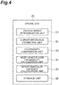
- the cruise ECU 25 includes a vehicle speed determination unit (low speed determination unit) 31, a curvature-radius estimation unit 32, a coordinate conversion unit 33, a host-vehicle-lane probability calculation unit (preceding-vehicle presence/absence determination unit) 34, an inter-vehicular distance calculation unit 35, and a storage unit 36.
- the vehicle speed determination unit 31 determines whether or not the host-vehicle speed of the host vehicle 2 detected by the vehicle speed sensor 11 is equal to or lower than a determination threshold value.
- the determination threshold value is 40 km/h, for example.
- the curvature-radius estimation unit 32 estimates a curvature radius R of a road, on which the host vehicle 2 is traveling, based on a tire angle ⁇ T to be described below, as illustrated in FIG. 5 .
- the detailed description thereof is as follows.
- the curvature-radius estimation unit 32 estimates the curvature radius R of the curved road, on which the host vehicle 2 is traveling, based on the yaw rate detected by the yaw rate sensor 13 and the host-vehicle speed detected by the vehicle speed sensor 11.
- the coordinate conversion unit 33 converts a position A of the preceding vehicle 3 in a first coordinate system in which a curve (estimated centerline E) corresponding to the curved road is used as a reference to a position in a second coordinate system in which a straight line L PC along a straight traveling direction Y of the host vehicle 2 is used as a reference.
- the coordinate conversion unit 33 converts positions A 1 , A 2 , A 3 , and A 4 of the preceding vehicle 3 in the first coordinate system illustrated in FIG. 7(a) to positions C 1 and C 2 in the second coordinate system illustrated in FIG. 7(b) .
- the host-vehicle-lane probability calculation unit 34 calculates a probability (host-vehicle-lane probability) that the preceding vehicle
- the host-vehicle-lane probability calculation unit 34 collates the position A of the preceding vehicle 3 with host-vehicle-lane probability calculating maps M 1 and M 2 (refer to FIG. 8 ) so as to calculate a probability that the preceding vehicle 3 is present on the host-vehicle lane 5.
- the host-vehicle-lane probability calculation unit 34 calculates the probability that the preceding vehicle 3 is present on the host-vehicle lane 5, based on a distance m from the host vehicle 2 to the preceding vehicle 3 in a vehicle width direction X orthogonal to the straight traveling direction Y of the host vehicle 2.
- a numerical value indicating the host-vehicle-lane probability is set based on the distance m (refer to FIG. 6 ) from the host vehicle 2 to the preceding vehicle 3 in the vehicle width direction X. For example, when the preceding vehicle 3 is present in front of the host vehicle 2, the host-vehicle-lane probability is set to 100 [%]. As the preceding vehicle 3 is separated from the host vehicle 2 in the vehicle width direction X, the host-vehicle-lane probability is reduced to 80 [%], 60 [%], or 0 [%]. Incidentally, the host-vehicle-lane probability may change depending on whether a target object such as the preceding vehicle 3 is present on the right side of the host vehicle 2 or the target object is present on the left side of the host vehicle 2.
- the host-vehicle-lane probability calculation unit 34 may change the host-vehicle-lane probability depending on whether or not the host vehicle 2 travels on a general road.
- the host-vehicle-lane probability calculation unit 34 may change the host-vehicle-lane probability depending on whether or not the host vehicle travels on a limited highway (for example, expressway).
- a limited highway for example, expressway.
- the host-vehicle-lane probability calculating map M 1 illustrated in FIG. 8(a) is applied, when the host vehicle 2 travels on the expressway.
- the host-vehicle-lane probability calculating map M 2 illustrated in FIG. 8(b) is applied, when the host vehicle 2 travels on the general way.
- a bicycle, a pedestrian, or the like will be present on the left (sidewalk side) of a host-vehicle position, and there is a low possibility that a vehicle travels on the left thereof.
- a low host-vehicle-lane probability is set (for example, 0 [%]).
- a relatively high host-vehicle-lane probability is set (for example, 60 [%]).
- the inter-vehicular distance calculation unit 35 calculates the inter-vehicular distance D between the host vehicle 2 and the preceding vehicle 3.
- the inter-vehicular distance calculation unit 35 calculates the inter-vehicular distance D (refer to FIG. 1 ) between the host vehicle 2 and the preceding vehicle 3, based on the position of the preceding vehicle 3 acquired by the radar sensor 12. Calculation of the inter-vehicular distance D when the host vehicle 2 is traveling on the curved road will be described below.
- the host-vehicle-lane probability calculating maps M 1 and M 2 are stored, for example.
- data to be used for estimating the curvature radius R is stored.
- An example of the data to be used for estimating the curvature radius R includes data related to a wheel base L WB (refer to FIG. 5 ) of the host vehicle 2.
- the cruise ECU 25 transmits command signals to the ECUs 21 to 24 so as to control the host vehicle 2 that needs to maintain the inter-vehicular distance D between the preceding vehicle 3 and the host vehicle 2.
- the cruise ECU 25 transmits the command signals to the ECUs 21 to 24 so as to control the host-vehicle speed at a constant speed.
- the cruise ECU 25 transmits a command signal to the engine ECU 21 so as to control an engine output.
- the cruise ECU 25 transmits a command signal to the transmission ECU 22 so as to control a transmission.
- the cruise ECU 25 controls the EBS/ABS ECU 23 so as to control the brake.
- the host vehicle 2 includes an engine retarder.
- the engine retarder opens an exhaust valve between an end of an intake stroke and a start of a compression stroke of the engine and allows high-pressure exhaust in an exhaust pipe to flow back to a cylinder. Consequently, a compression pressure in the cylinder increases such that an effect of an exhaust brake increases.
- the exhaust brake increases exhaust resistance of the engine, thereby increasing an effect of an engine brake.
- the cruise ECU 25 transmits a command signal to the vehicle control ECU 24.
- the vehicle control ECU 24 operates the engine retarder so as to decelerate the host vehicle 2 based on the command signal. Consequently, the brake of the host vehicle 2 is less frequently used, and wear of a brake shoe is limited.
- a midpoint P T illustrated in FIG. 5 is a tread midpoint that is a center point between right and left front wheels (wheels 6).
- the curvature radius R is a distance from a center point O of a circle E 1 including an arc on which the host vehicle 2 turns to the midpoint P T .
- the tire angle ⁇ T is an angle formed between a straight line along the straight traveling direction Y of the host vehicle 2 at the midpoint P T and a tangential line L PT of the circle E 1 .
- the wheel base L WB of the host vehicle 2 is a distance between a front axle and a rear axle.
- the tire angle ⁇ T can be expressed by Expression (3) below.
- the damping coefficient K of steering is a vehicle specific value and can be measured.
- the distance m means a distance between the estimated centerline E and the preceding vehicle 3 in a direction orthogonal to an estimated traveling direction of the preceding vehicle 3.
- the distance m may be a distance between the estimated centerline E and the center of the preceding vehicle 3 in the vehicle width direction.
- the estimated traveling direction is a direction along a curve E or a direction along a straight line L QT , for example.
- L Y y
- L X x
- a sign of L X when the preceding vehicle 3 is present on the right from the center of the host vehicle 2 in the vehicle width direction X is set to "plus”.
- a sign of L X when the preceding vehicle 3 is present on the left from the center of the host vehicle 2 in the vehicle width direction X is set to "minus".
- R represents an estimated curvature radius of the curved road, on which the host vehicle 2 is traveling.
- a sign of the curvature radius R when the road has a right-hand curve is set to "plus”.
- the position of the preceding vehicle 3 is set as a point A, and a center point of a virtual circle of the curved road having the curvature radius R is set as the point O.
- An intersection point of a straight line L OB with a straight line L AB is set as a point B.
- the straight line L OB is parallel to the straight traveling direction Y, the straight line L OB passing through the center point O.
- the straight line L AB is parallel to the vehicle width direction X, the straight line L AB passing through the position A of the preceding vehicle 3.
- O represents the center point of the virtual circle having the curvature radius R
- P represents a position of the host vehicle 2.
- Q represents an intersection point of a straight line L OA connecting the center point O and the point A which is the position of the preceding vehicle 3 with the estimated centerline E which is an arc of the virtual circle.
- ⁇ POQ represents an intersection angle between a straight line L OP and a straight line L OQ
- ⁇ OAB represents an intersection angle between the straight line L OB and the straight line L AB .
- the straight line L OP is parallel to the straight line L AB .
- intersection angle ⁇ POQ is equal to ⁇ OAB , and thus Expression (10) below is satisfied.
- Expressions (1) and (11) above are applied to a map, and thereby it is possible to convert the position A of the preceding vehicle 3 to a position in the second coordinate system in which the straight line L PC extending in the straight traveling direction Y is used as a reference, as illustrated in FIG. 7(b) .
- the coordinate conversion unit 33 determines whether the curved road has the right-hand curve or the left-hand curve based on a sign (+ or -) of a signal indicating a horizontal position of the preceding vehicle 3 detected by the radar sensor 12.
- the coordinate conversion unit determines that the curved road has the right-hand curve.
- the coordinate conversion unit determines that the curved road has the left-hand curve.
- the coordinate conversion unit 33 converts a position of the preceding vehicle 3 that is present at the point A 1 at which L X > 0 and m > 0 to a position of the point C 1 in the second coordinate system (L X ⁇ m > 0), for example.
- the coordinate conversion unit 33 converts a position of the preceding vehicle 3 that is present at the point A 2 at which L X > 0 and m ⁇ 0 to a position of the point C 2 in the second coordinate system (L X ⁇ m ⁇ 0), for example.
- the coordinate conversion unit 33 converts the position of the preceding vehicle 3 that is present at the point A 3 at which L X ⁇ 0 and m > 0 to a position of the point C 1 in the second coordinate system (L X ⁇ m > 0), for example.
- the coordinate conversion unit 33 converts a position of the preceding vehicle 3 that is present at the point A 4 at which L X ⁇ 0 and m ⁇ 0 to a position of the point C 2 in the second coordinate system (L X ⁇ m ⁇ 0), for example.
- the cruise ECU 25 acquires information of the steering angle of the host vehicle 2 output from the steering angle sensor 14 (Step S1).
- the cruise ECU 25 acquires information of the host-vehicle speed output from the vehicle speed sensor 11 (Step S2).
- the vehicle speed determination unit 31 of the cruise ECU 25 determines whether or not the host-vehicle speed is equal to or lower than 40 km/h (Step S3).
- the process proceeds to Step S4.
- the host-vehicle speed is higher than 40 km/h, the process proceeds to Step S5.
- Step S4 the curvature-radius estimation unit 32 of the cruise ECU 25 estimates the curvature radius R by using Ackermann' s formula. Specifically, the curvature-radius estimation unit 32 calculates the curvature radius R from the wheel base L WB and the steering angle ⁇ S of the host vehicle 2 by using Expression (4).
- the cruise ECU 25 executes Step S6 after Step S4.
- Step S6 the cruise ECU 25 acquires information (x, y) related to the position of the preceding vehicle 3 output from the radar sensor 12.
- Step S7 the coordinate conversion unit 33 of the cruise ECU 25 converts the position of the preceding vehicle 3 to the position in the second coordinate system in which the straight line L PC along the straight traveling direction Y is used as a reference. Specifically, the coordinate conversion unit 33 calculates the distance m by using Expression (1). The coordinate conversion unit 33 calculates the arc PQ by using Expression (11).
- the cruise ECU 25 allows the process to proceed to Step S8 after Step S7.
- Step S5 the curvature-radius estimation unit 32 of the cruise ECU 25 calculates the curvature radius R of the curved road, on which the host vehicle 2 is traveling, by using a computation expression of a yaw rate base as in the related art.
- the cruise ECU 25 executes Step S6 after Step S5 and allows the process to proceed to Step S8.
- Step S8 the host-vehicle-lane probability calculation unit 34 of the cruise ECU 25 collates the positions C 1 and C 2 of the preceding vehicle 3 in the second coordinate system with the host-vehicle-lane probability calculating map M 1 (or M 2 ) (Step S8). From a result of collation, the host-vehicle-lane probability calculation unit 34 reads a corresponding numerical value on the host-vehicle-lane probability calculating map M 1 and sets the numerical value as the host-vehicle-lane probability of the preceding vehicle 3.
- Step S9 the host-vehicle-lane probability calculation unit 34 of the cruise ECU 25 determines whether or not the host-vehicle-lane probability is equal to or higher than 80%.
- the cruise ECU 25 allows the process to proceed to Step S10 and determines that the preceding vehicle is present on the host-vehicle lane.
- the cruise ECU 25 allows the process to proceed to Step S11 and determines that the preceding vehicle is not present on the host-vehicle lane.
- the process is ended.
- the vehicle control ECU 24 of the vehicle control system 1 controls the inter-vehicular distance between the host vehicle 2 and the preceding vehicle 3 and performs control of maintaining the host-vehicle speed at the constant speed.
- the vehicle control system 1 executes the constant speed traveling control and the inter-vehicular distance control in the entire vehicle speed range regardless of the host-vehicle speed.
- the cruise ECU 25 of the vehicle control system 1 of the embodiment includes the vehicle speed determination unit 31 and estimates the curvature radius R of the road, on which the host vehicle 2 is traveling, based on the steering angle ⁇ S , when the host-vehicle speed is equal to or lower than the determination threshold value. Consequently, it is possible to estimate the curvature radius R without using the yaw rate.
- the host-vehicle speed is equal to or lower than the determination threshold value, it is possible to estimate the curvature radius R of the road, on which the host vehicle is traveling, based on the steering angle ⁇ S while it is possible to limit an influence of an error.
- the coordinate conversion unit 33 of the cruise ECU 25 converts the position of the preceding vehicle 3 to the position in the second coordinate system. The position in the second coordinate system is obtained with the straight line L PC along the straight traveling direction Y of the host vehicle 2 as a reference. Therefore, it is possible to significantly reduce a computation load more than in the case of converting the entire coordinate system as in the related art
- the radar sensor 12 of the vehicle control system 1 detects the first distance L Y from the host vehicle to the preceding vehicle 3 in the straight traveling direction of the host vehicle 2 and the second distance L X from the host vehicle 2 to the preceding vehicle 3 in the vehicle width direction X orthogonal to the straight traveling direction Y.
- the coordinate conversion unit 33 calculates the distance m between the preceding vehicle 3 and the tangential line L QT of the curve (estimated centerline E) corresponding to the curvature radius R, the curve passing through the center of the host vehicle 2 in the vehicle width direction X.
- the host-vehicle-lane probability calculation unit 34 calculates the probability that the preceding vehicle 3 is present on the host-vehicle lane, based on the distance m.
- the vehicle control system 1 it is possible to calculate the probability that the preceding vehicle 3 is present on the host-vehicle lane and reduce the computation load, based on the second distance L X from the host vehicle 2 to the preceding vehicle 3 in the vehicle width direction X.
- the host vehicle 2 includes the engine retarder.
- the vehicle control ECU 24 can control the engine retarder to decelerate the host vehicle 2. Consequently, it is possible to appropriately maintain the inter-vehicular distance between the host vehicle 2 and the preceding vehicle 3. As a result, it is possible to reduce wear of the brake shoe during deceleration of the host vehicle 2.
- the radar sensor 12 is included, is described as a preceding-vehicle detection sensor that detects the position of the preceding vehicle 3 ahead of the host vehicle 2; however, the preceding-vehicle detection sensor is not limited to the radar sensor 12.
- the positional information of the preceding vehicle may be acquired by using an in-vehicle camera (image sensor), inter-vehicle communication, or the like.
- the low speed determination unit determines whether or not the host-vehicle speed is equal to or lower than 40 km/h (determination threshold value); however, the determination threshold value is not limited to 40 km/h and may be a different vehicle speed.
- the determination threshold value may be a value that is lower than 40 km/h or higher than 40 km/h.
- the determination threshold value can be set based on an experiment or data obtained in the past.
- the probability that the preceding vehicle 3 is present on the host-vehicle lane is calculated by using the host-vehicle-lane probability calculating maps.
- the host-vehicle-lane probability may be calculated by a calculation process based on the position of the preceding vehicle 3, for example.
- 1 vehicle control system (preceding-vehicle determination apparatus), 2: host vehicle, 3: preceding vehicle, 5: host-vehicle lane, 11: vehicle speed sensor, 12: radar sensor (preceding-vehicle detection sensor), 14: steering angle sensor, 24: vehicle control ECU, 25: cruise ECU, 31: vehicle speed determination unit (low speed determination unit), 32: curvature-radius estimation unit, 33: coordinate conversion unit, 34: host-vehicle-lane probability calculation unit (preceding-vehicle presence/absence determination unit), L QT : tangential line, L X : second distance, L Y : first distance, X: vehicle width direction, Y: straight traveling direction.
Landscapes
- Engineering & Computer Science (AREA)
- Transportation (AREA)
- Mechanical Engineering (AREA)
- Automation & Control Theory (AREA)
- Chemical & Material Sciences (AREA)
- Combustion & Propulsion (AREA)
- Physics & Mathematics (AREA)
- Mathematical Physics (AREA)
- Traffic Control Systems (AREA)
- Control Of Driving Devices And Active Controlling Of Vehicle (AREA)
Applications Claiming Priority (2)
| Application Number | Priority Date | Filing Date | Title |
|---|---|---|---|
| JP2017058012A JP2018158689A (ja) | 2017-03-23 | 2017-03-23 | 先行車判定装置及び車両制御システム |
| PCT/JP2018/002561 WO2018173479A1 (fr) | 2017-03-23 | 2018-01-26 | Appareil de détermination de véhicule précédent et système de commande de véhicule |
Publications (2)
| Publication Number | Publication Date |
|---|---|
| EP3604067A1 true EP3604067A1 (fr) | 2020-02-05 |
| EP3604067A4 EP3604067A4 (fr) | 2021-01-06 |
Family
ID=63584341
Family Applications (1)
| Application Number | Title | Priority Date | Filing Date |
|---|---|---|---|
| EP18772402.6A Withdrawn EP3604067A4 (fr) | 2017-03-23 | 2018-01-26 | Appareil de détermination de véhicule précédent et système de commande de véhicule |
Country Status (5)
| Country | Link |
|---|---|
| US (1) | US20200039515A1 (fr) |
| EP (1) | EP3604067A4 (fr) |
| JP (1) | JP2018158689A (fr) |
| CN (1) | CN110121451A (fr) |
| WO (1) | WO2018173479A1 (fr) |
Families Citing this family (8)
| Publication number | Priority date | Publication date | Assignee | Title |
|---|---|---|---|---|
| JP6661695B2 (ja) * | 2018-05-09 | 2020-03-11 | 三菱電機株式会社 | 移動体検出装置、車両制御システム、移動体検出方法および車両制御方法 |
| JP7133400B2 (ja) * | 2018-08-31 | 2022-09-08 | 日立Astemo株式会社 | 車両制御装置、車両制御方法および車両追従走行システム |
| JP7352432B2 (ja) * | 2019-10-03 | 2023-09-28 | 株式会社Subaru | 車外環境認識装置 |
| WO2021152650A1 (fr) * | 2020-01-27 | 2021-08-05 | 三菱電機株式会社 | Système de détermination de véhicule précédent et procédé de détermination de véhicule précédent |
| CN113359147B (zh) * | 2020-03-06 | 2023-08-18 | 宇通客车股份有限公司 | 一种车辆及目标物运动状态的判断方法和装置 |
| CN112699575A (zh) * | 2021-01-22 | 2021-04-23 | 中汽创智科技有限公司 | 一种虚拟车辆测试平台中相对位置测算方法及系统 |
| DE102021109425B3 (de) * | 2021-04-15 | 2022-07-21 | Bayerische Motoren Werke Aktiengesellschaft | Verfahren zum Steuern eines Fahrzeugs und Steuervorrichtung für ein Fahrzeug |
| CN114396892B (zh) * | 2021-12-02 | 2023-08-25 | 重庆交通大学 | 轨道交通曲线轨道曲率测量方法 |
Family Cites Families (16)
| Publication number | Priority date | Publication date | Assignee | Title |
|---|---|---|---|---|
| JP3470453B2 (ja) * | 1995-04-06 | 2003-11-25 | 株式会社デンソー | 車間距離制御装置 |
| JP2000038050A (ja) * | 1998-07-23 | 2000-02-08 | Hino Motors Ltd | 自動車用走行制御装置 |
| JP4066573B2 (ja) * | 1999-09-22 | 2008-03-26 | 株式会社デンソー | 先行車選択装置、車間制御装置及び記録媒体 |
| JP2002175599A (ja) * | 2000-12-05 | 2002-06-21 | Hitachi Ltd | 先行車または物標の車線位置推定装置 |
| JP3975922B2 (ja) * | 2003-01-17 | 2007-09-12 | トヨタ自動車株式会社 | カーブ半径推定装置 |
| AU2003262253A1 (en) * | 2003-08-20 | 2005-03-10 | Hitachi, Ltd. | Device and method for selecting preceding vehicle |
| JP4134885B2 (ja) * | 2003-11-10 | 2008-08-20 | トヨタ自動車株式会社 | カーブ推定装置およびこれを用いた走行制御装置 |
| JP2006098983A (ja) * | 2004-09-30 | 2006-04-13 | Nippon Seiki Co Ltd | 表示装置 |
| JP4919681B2 (ja) | 2006-03-22 | 2012-04-18 | Udトラックス株式会社 | 車載用レーダ装置 |
| JP4811147B2 (ja) * | 2006-06-15 | 2011-11-09 | トヨタ自動車株式会社 | 車両制御装置 |
| JP2009149173A (ja) * | 2007-12-19 | 2009-07-09 | Mitsubishi Fuso Truck & Bus Corp | オートクルーズ装置 |
| JP5136657B2 (ja) * | 2009-01-22 | 2013-02-06 | トヨタ自動車株式会社 | カーブ半径推定装置 |
| US8781644B2 (en) * | 2011-03-21 | 2014-07-15 | Denso Corporation | Method and apparatus for recognizing shape of road for vehicles |
| KR101528882B1 (ko) * | 2013-07-19 | 2015-06-15 | 현대모비스 주식회사 | 요 레이트 센서의 오프셋 보정 장치와 방법 및 상기 장치를 구비하는 차량 속도 제어 시스템 |
| JP5949721B2 (ja) * | 2013-10-10 | 2016-07-13 | 株式会社デンソー | 先行車選択装置 |
| CN105667509A (zh) * | 2015-12-30 | 2016-06-15 | 苏州安智汽车零部件有限公司 | 一种用于汽车自适应巡航控制系统的弯道控制系统及方法 |
-
2017
- 2017-03-23 JP JP2017058012A patent/JP2018158689A/ja active Pending
-
2018
- 2018-01-26 US US16/496,138 patent/US20200039515A1/en not_active Abandoned
- 2018-01-26 WO PCT/JP2018/002561 patent/WO2018173479A1/fr unknown
- 2018-01-26 CN CN201880005503.4A patent/CN110121451A/zh active Pending
- 2018-01-26 EP EP18772402.6A patent/EP3604067A4/fr not_active Withdrawn
Also Published As
| Publication number | Publication date |
|---|---|
| WO2018173479A1 (fr) | 2018-09-27 |
| EP3604067A4 (fr) | 2021-01-06 |
| US20200039515A1 (en) | 2020-02-06 |
| JP2018158689A (ja) | 2018-10-11 |
| CN110121451A (zh) | 2019-08-13 |
Similar Documents
| Publication | Publication Date | Title |
|---|---|---|
| EP3604067A1 (fr) | Appareil de détermination de véhicule précédent et système de commande de véhicule | |
| US10515278B2 (en) | Driving assistance device | |
| CN109017777B (zh) | 驾驶辅助装置 | |
| EP1818231B1 (fr) | Système de commande de véhicule | |
| US9852633B2 (en) | Travel assist apparatus and travel assist method | |
| US9505401B2 (en) | Driving support apparatus and driving support method | |
| US8150591B2 (en) | Vehicle travel speed control method | |
| US20200139963A1 (en) | Vehicle and Control Method for the Same | |
| EP3715204A1 (fr) | Dispositif de commande de véhicule | |
| CN109969174B (zh) | 车辆控制装置 | |
| WO2012081096A1 (fr) | Dispositif d'aide au déplacement, procédé d'aide au déplacement et véhicule | |
| CN111361564A (zh) | 一种考虑效益最大化的车道变更系统及综合决策方法 | |
| CN112208533B (zh) | 车辆控制系统、车辆控制方法及存储介质 | |
| KR20140057583A (ko) | 자동차용 안전 장치 | |
| CN110949375B (zh) | 信息处理系统以及服务器 | |
| CN112406820B (zh) | 多车道增强型自动紧急制动系统控制方法 | |
| EP3923258A1 (fr) | Dispositif de fonctionnement arithmétique pour véhicule | |
| CN109501798B (zh) | 行驶控制装置、以及行驶控制方法 | |
| CN110007301B (zh) | 物体识别装置、物体识别方法以及车辆 | |
| JP2012040914A (ja) | 車両用挙動制御装置 | |
| JP6609292B2 (ja) | 車外環境認識装置 | |
| JP4919849B2 (ja) | 車載用レーダ装置 | |
| US11205343B2 (en) | Methods and systems for interpretating traffic signals and negotiating signalized intersections | |
| JP7459445B2 (ja) | 走行経路生成システム及び車両運転支援システム | |
| CN113492843B (zh) | 车载装置、车辆以及控制方法 |
Legal Events
| Date | Code | Title | Description |
|---|---|---|---|
| STAA | Information on the status of an ep patent application or granted ep patent |
Free format text: STATUS: THE INTERNATIONAL PUBLICATION HAS BEEN MADE |
|
| PUAI | Public reference made under article 153(3) epc to a published international application that has entered the european phase |
Free format text: ORIGINAL CODE: 0009012 |
|
| STAA | Information on the status of an ep patent application or granted ep patent |
Free format text: STATUS: REQUEST FOR EXAMINATION WAS MADE |
|
| 17P | Request for examination filed |
Effective date: 20191023 |
|
| AK | Designated contracting states |
Kind code of ref document: A1 Designated state(s): AL AT BE BG CH CY CZ DE DK EE ES FI FR GB GR HR HU IE IS IT LI LT LU LV MC MK MT NL NO PL PT RO RS SE SI SK SM TR |
|
| AX | Request for extension of the european patent |
Extension state: BA ME |
|
| DAV | Request for validation of the european patent (deleted) | ||
| DAX | Request for extension of the european patent (deleted) | ||
| A4 | Supplementary search report drawn up and despatched |
Effective date: 20201202 |
|
| RIC1 | Information provided on ipc code assigned before grant |
Ipc: B60W 30/18 20120101ALI20201127BHEP Ipc: B60W 40/072 20120101ALI20201127BHEP Ipc: B60W 30/16 20200101AFI20201127BHEP Ipc: B60W 30/165 20200101ALI20201127BHEP |
|
| STAA | Information on the status of an ep patent application or granted ep patent |
Free format text: STATUS: THE APPLICATION IS DEEMED TO BE WITHDRAWN |
|
| 18D | Application deemed to be withdrawn |
Effective date: 20210702 |