EP3591771A2 - Vorrichtung und verfahren zur kontakteinführungs- und -halteprüfung - Google Patents
Vorrichtung und verfahren zur kontakteinführungs- und -halteprüfung Download PDFInfo
- Publication number
- EP3591771A2 EP3591771A2 EP19174225.3A EP19174225A EP3591771A2 EP 3591771 A2 EP3591771 A2 EP 3591771A2 EP 19174225 A EP19174225 A EP 19174225A EP 3591771 A2 EP3591771 A2 EP 3591771A2
- Authority
- EP
- European Patent Office
- Prior art keywords
- contact
- test probe
- insertion tip
- electrical connector
- hole
- Prior art date
- Legal status (The legal status is an assumption and is not a legal conclusion. Google has not performed a legal analysis and makes no representation as to the accuracy of the status listed.)
- Granted
Links
Images













Classifications
-
- G—PHYSICS
- G01—MEASURING; TESTING
- G01R—MEASURING ELECTRIC VARIABLES; MEASURING MAGNETIC VARIABLES
- G01R1/00—Details of instruments or arrangements of the types included in groups G01R5/00 - G01R13/00 and G01R31/00
- G01R1/02—General constructional details
- G01R1/04—Housings; Supporting members; Arrangements of terminals
- G01R1/0408—Test fixtures or contact fields; Connectors or connecting adaptors; Test clips; Test sockets
-
- H—ELECTRICITY
- H01—ELECTRIC ELEMENTS
- H01R—ELECTRICALLY-CONDUCTIVE CONNECTIONS; STRUCTURAL ASSOCIATIONS OF A PLURALITY OF MUTUALLY-INSULATED ELECTRICAL CONNECTING ELEMENTS; COUPLING DEVICES; CURRENT COLLECTORS
- H01R13/00—Details of coupling devices of the kinds covered by groups H01R12/70 or H01R24/00 - H01R33/00
- H01R13/46—Bases; Cases
- H01R13/52—Dustproof, splashproof, drip-proof, waterproof, or flameproof cases
- H01R13/521—Sealing between contact members and housing, e.g. sealing insert
-
- H—ELECTRICITY
- H01—ELECTRIC ELEMENTS
- H01R—ELECTRICALLY-CONDUCTIVE CONNECTIONS; STRUCTURAL ASSOCIATIONS OF A PLURALITY OF MUTUALLY-INSULATED ELECTRICAL CONNECTING ELEMENTS; COUPLING DEVICES; CURRENT COLLECTORS
- H01R43/00—Apparatus or processes specially adapted for manufacturing, assembling, maintaining, or repairing of line connectors or current collectors or for joining electric conductors
- H01R43/20—Apparatus or processes specially adapted for manufacturing, assembling, maintaining, or repairing of line connectors or current collectors or for joining electric conductors for assembling or disassembling contact members with insulating base, case or sleeve
-
- G—PHYSICS
- G01—MEASURING; TESTING
- G01R—MEASURING ELECTRIC VARIABLES; MEASURING MAGNETIC VARIABLES
- G01R1/00—Details of instruments or arrangements of the types included in groups G01R5/00 - G01R13/00 and G01R31/00
- G01R1/02—General constructional details
- G01R1/06—Measuring leads; Measuring probes
- G01R1/067—Measuring probes
- G01R1/06794—Devices for sensing when probes are in contact, or in position to contact, with measured object
-
- G—PHYSICS
- G01—MEASURING; TESTING
- G01R—MEASURING ELECTRIC VARIABLES; MEASURING MAGNETIC VARIABLES
- G01R31/00—Arrangements for testing electric properties; Arrangements for locating electric faults; Arrangements for electrical testing characterised by what is being tested not provided for elsewhere
- G01R31/50—Testing of electric apparatus, lines, cables or components for short-circuits, continuity, leakage current or incorrect line connections
- G01R31/66—Testing of connections, e.g. of plugs or non-disconnectable joints
- G01R31/68—Testing of releasable connections, e.g. of terminals mounted on a printed circuit board
- G01R31/69—Testing of releasable connections, e.g. of terminals mounted on a printed circuit board of terminals at the end of a cable or a wire harness; of plugs; of sockets, e.g. wall sockets or power sockets in appliances
-
- H—ELECTRICITY
- H01—ELECTRIC ELEMENTS
- H01R—ELECTRICALLY-CONDUCTIVE CONNECTIONS; STRUCTURAL ASSOCIATIONS OF A PLURALITY OF MUTUALLY-INSULATED ELECTRICAL CONNECTING ELEMENTS; COUPLING DEVICES; CURRENT COLLECTORS
- H01R11/00—Individual connecting elements providing two or more spaced connecting locations for conductive members which are, or may be, thereby interconnected, e.g. end pieces for wires or cables supported by the wire or cable and having means for facilitating electrical connection to some other wire, terminal, or conductive member, blocks of binding posts
-
- H—ELECTRICITY
- H01—ELECTRIC ELEMENTS
- H01R—ELECTRICALLY-CONDUCTIVE CONNECTIONS; STRUCTURAL ASSOCIATIONS OF A PLURALITY OF MUTUALLY-INSULATED ELECTRICAL CONNECTING ELEMENTS; COUPLING DEVICES; CURRENT COLLECTORS
- H01R11/00—Individual connecting elements providing two or more spaced connecting locations for conductive members which are, or may be, thereby interconnected, e.g. end pieces for wires or cables supported by the wire or cable and having means for facilitating electrical connection to some other wire, terminal, or conductive member, blocks of binding posts
- H01R11/11—End pieces or tapping pieces for wires, supported by the wire and for facilitating electrical connection to some other wire, terminal or conductive member
- H01R11/18—End pieces terminating in a probe
-
- H—ELECTRICITY
- H01—ELECTRIC ELEMENTS
- H01R—ELECTRICALLY-CONDUCTIVE CONNECTIONS; STRUCTURAL ASSOCIATIONS OF A PLURALITY OF MUTUALLY-INSULATED ELECTRICAL CONNECTING ELEMENTS; COUPLING DEVICES; CURRENT COLLECTORS
- H01R13/00—Details of coupling devices of the kinds covered by groups H01R12/70 or H01R24/00 - H01R33/00
- H01R13/46—Bases; Cases
- H01R13/52—Dustproof, splashproof, drip-proof, waterproof, or flameproof cases
- H01R13/5205—Sealing means between cable and housing, e.g. grommet
-
- H—ELECTRICITY
- H01—ELECTRIC ELEMENTS
- H01R—ELECTRICALLY-CONDUCTIVE CONNECTIONS; STRUCTURAL ASSOCIATIONS OF A PLURALITY OF MUTUALLY-INSULATED ELECTRICAL CONNECTING ELEMENTS; COUPLING DEVICES; CURRENT COLLECTORS
- H01R13/00—Details of coupling devices of the kinds covered by groups H01R12/70 or H01R24/00 - H01R33/00
- H01R13/46—Bases; Cases
- H01R13/52—Dustproof, splashproof, drip-proof, waterproof, or flameproof cases
- H01R13/5219—Sealing means between coupling parts, e.g. interfacial seal
Definitions
- the present disclosure generally systems and methods for assembling a wire bundle in which each wire terminates at a respective electrically conductive contact.
- this disclosure relates to systems and methods for inserting such contacts into electrical connectors.
- a connector is generally mounted upon the end portions of a plurality of conductors, such as optical fibers, electrically conductive wires or the like.
- the connector is mated with another connector to connect respective bundles of the conductors.
- the connector is connected to a receptacle of an instrument or the like.
- each connector it is conventional for each connector to comprise a mating shell which is mechanically connected to the shell of the other connector when the two connectors are brought into operative relationship.
- Each connector also includes a contact-receiving insert.
- the insert is typically made of dielectric material and is in the form of a plate having an inner surface which confronts the corresponding insert of the other connector, and an opposite, outer surface which is parallel to the inner surface. Numerous holes penetrate this member, opening at their opposite ends at the inner and outer surfaces respectively of the insert.
- the wire is prepared for attachment to the connector by stripping the electrically insulative jacket from the end of the wire so as to expose the conductive core, and crimping a contact onto the conductor.
- This contact is in the form of a pin or a receptacle (referred to hereinafter as a "socket").
- the contact is introduced into a hole in the aforementioned insert by way of the outer surface thereof and, in the case of a pin, projects beyond the inner surface of the insert.
- a further problem is that a contact may be incompletely inserted or otherwise improperly seated in a hole of the insert. If a contact is improperly seated, it is possible that the retention force exerted by the retention clips inside the connector may be insufficient to retain the pin or socket in contact with a corresponding socket or pin if the wire to which the pin or socket is attached is pulled with sufficient force or if the connectors are shaken, for example, by vibrations.
- testing for unseated or improperly seated contacts is usually manual.
- the person can either pull on a wire or push on a contact to test retention. Similar issues regarding inconsistent results arise during manual retention testing. Since there is no way for an operator to gage the pulling or pushing force being applied, too little force may result in a faulty test and too much force may again cause damage to the wire or the connector.
- Inserting wires properly while reducing unseated contact occurrences is needed for the electrical industry across multiple sectors.
- a solution is needed for both ends of the bundles.
- a solution that would enable predefined consistent quality testing is needed to address the problem of unseated contacts in wire bundle assemblies.
- a method as defined in claim 1 for inserting and retention testing an electrically conductive contact in an electrical connector.
- an apparatus as defined in claim 10 for inserting and retention testing an electrically conductive contact in an electrical connector.
- a method as defined in claim 13 for inserting and retention testing an electrically conductive contact in an electrical connector.
- a method as defined in claim 15 for inserting an electrically conductive contact in a hole in an electrical connector.
- the subject matter disclosed herein is directed to an apparatus and methods for inserting and retention testing an electrically conductive contact in an electrical connector.
- the method includes the following steps: manually partially inserting the contact into a hole formed inside the electrical connector; inserting the contact further into the hole by pushing the contact along an axis using an insertion tip that is aligned with the axis and that displaces in a first direction along the axis during inserting; and after inserting the contact further into the hole, testing retention of the contact inside the electrical connector by pushing the contact along the axis using a test probe that is aligned with the axis and that displaces in a second direction opposite to the first direction during retention testing.
- the force exerted by the test probe on the contact is less than a specified contact retention force.
- the method further includes generating an alert signal if the test probe displaces along the axis in the second direction by more than a specified distance during retention testing.
- One aspect of the subject matter disclosed in detail below is a method for inserting and retention testing an electrically conductive contact in an electrical connector, comprising: (a) placing an electrical connector underneath an insertion tip and above a test probe; (b) coupling a contact to the insertion tip; (c) moving the test probe toward the electrical connector until an end of the test probe is at a starting position; (d) activating a first linear actuator to insert the contact further into a hole in the electrical connector by moving the contact in a first direction opposite to the second direction for a sufficient distance that an end of the contact would contact the end of the test probe at the starting position and then displace the test probe in the first direction away from the starting position provided that the insertion tip and test probe are in the same hole; (e) using a position sensor to detect whether the position of the end of the test probe at the end of step (d) is separated from the starting position by at least a first distance or not; and (f) if step (e) detects that the position of the end of the test probe at the end of step
- Another aspect of the subject matter disclosed in detail below is a method for inserting and retention testing an electrically conductive contact in an electrical connector, comprising: manually partially inserting the contact into a hole formed inside the electrical connector; inserting the contact further into the hole by pushing the contact along an axis using an insertion tip that is aligned with the axis and that displaces in a first direction along the axis during inserting; and after inserting the contact further into the hole, testing retention of the contact inside the electrical connector by pushing the contact along the axis using a test probe that is aligned with the axis and that displaces in a second direction opposite to the first direction during testing.
- the insertion tip may be in contact with one end of the contact, and during retention testing the test probe may be in contact with another end of the contact.
- the method may further comprise displacing the test probe along the axis in the second direction before inserting the contact further into the hole, the displacement of the test probe in the second direction before inserting the contact further into the hole being driven by applying a force manually.
- the method described in the preceding paragraph may further comprise one or more of the following steps: generating an electrical signal if the test probe does not displace along the axis in the first direction by at least a specified distance during inserting the contact further into the hole; causing the insertion tip to vibrate if the test probe does not displace along the axis in the first direction by at least a specified distance during inserting the contact further into the hole; and applying a force on the test probe that urges the test probe to displace along the axis in the second direction after inserting the contact further into the hole, wherein the force applied is less than a specified contact retention force.
- a further aspect of the subject matter disclosed in detail below is an apparatus for inserting and retention testing an electrically conductive contact in an electrical connector, comprising: a connector holder configured to hold an electrical connector; an insertion tip configured to contact one end of a contact partially inserted in a hole in the electrical connector while providing clearance for a wire that is terminated by the contact; an insertion tip displacement assembly configured to displace the insertion tip in a first direction along a first linear path to further insert the insertion tip in the hole in the electrical connector; a test probe configured to contact another end of the contact after the contact has been inserted further into the hole; and a test probe displacement assembly configured to displace the test probe in a second direction along a second linear path, wherein the second direction is opposite to the first direction, and the first and second linear paths partially overlap.
- the apparatus may further comprise: a controller configured to cause the insertion tip displacement assembly to displace the insertion tip along the first linear path in the first direction during a first portion of a time cycle and later cause the test probe displacement assembly to displace the test probe along the second linear path in the second direction during a second portion of the time cycle; and a position sensor that senses a position of the test probe and outputs signals representing the position of the test probe to the controller.
- a controller configured to cause the insertion tip displacement assembly to displace the insertion tip along the first linear path in the first direction during a first portion of a time cycle and later cause the test probe displacement assembly to displace the test probe along the second linear path in the second direction during a second portion of the time cycle
- a position sensor that senses a position of the test probe and outputs signals representing the position of the test probe to the controller.
- the controller may be further configured to generate an error signal if the test probe does not displace along the second linear path in the first direction by at least a specified distance during displacement of the insertion tip along the first linear path in the first direction.
- the apparatus may further comprise a vibrator mounted to the insertion tip displacement assembly, in which case the controller is further configured to activate the vibrator if the test probe does not displace along the second linear path in the first direction by at least a specified distance during displacement of the insertion tip along the first linear path in the first direction.
- the test probe displacement assembly may be configured to urge the test probe to displace along the second linear path in the second direction by applying a force that is less than a specified contact retention force, and the controller is further configured to generate an error signal if the test probe displaces along the second linear path in the second direction by more than a specified distance in response to application of the force by the test probe displacement assembly.
- the insertion tip displacement assembly may comprise: an insertion cylinder that causes the insertion tip to displace along the first linear path in the first direction in response to activation of the insertion cylinder; and a first return cylinder that causes the insertion tip to displace along the first linear path in the second direction in response to activation of the first return cylinder.
- the test probe displacement assembly may comprise a test cylinder that causes the test probe to displace along the second linear path in the second direction in response to activation of the test cylinder and a second return cylinder that causes the test probe to displace along the second linear path in the first direction in response to activation of the second return cylinder.
- the test probe displacement assembly may further comprise: a rotatable shaft; a manually operable activation lever fixedly mounted to one end of the shaft; a pinion gear fixedly mounted to the shaft and comprising a multiplicity of teeth; a test probe support shelf to which the test probe is fixedly mounted; and a rack affixed to the test probe support shelf and comprising a multiplicity of teeth, at least one tooth on the rack being interengaged with a pair of teeth on the pinion gear, wherein the test cylinder and the test probe support shelf are arranged so that the test probe support shelf is contacted by and displaced in a direction parallel to the second direction by one end of a piston rod of the test cylinder when the test cylinder is activated, but is not attached to the one end of the piston rod of the test cylinder.
- the test probe displacement assembly may further comprise a return block fixedly mounted to the shaft and disposed in a path of one end of a piston rod of the second return cylinder after the test probe support shelf has been displaced by the one end of the piston rod of the test cylinder.
- the test probe may be displaceable along the second linear path in the second direction by manual rotation of the activation lever while the test cylinder is inactive.
- a method for inserting an electrically conductive contact in a hole in an electrical connector comprising: (a) placing an electrical connector underneath an insertion tip and above a test probe; (b) coupling a contact to the insertion tip; (c) moving the test probe toward the electrical connector until an end of the test probe is at a starting position; (d) moving the insertion tip to insert the contact further into the hole in the electrical connector; (e) using a position sensor to detect whether the position of the end of the test probe at the end of step (c) is separated from the starting position by at least a specified distance or not; and (f) if step (e) detects that the position of the end of the test probe at the end of step (d) is not separated from the starting position by at least the specified, displaying symbology on a human-machine interface (or emitting/generating an audible or other perceptible signal) indicating that the contact and the test probe are not in the same hole.
- the apparatus and method disclosed in some detail below provides a technical solution to the technical problem of contacts which are not properly seated in electrical connectors during contact insertion.
- the position of a test probe is monitored during a contact insertion operation to detect instances wherein the inserted contact is not being retained with sufficient retention force to be considered as locked in place inside the electrical connector.
- the machine inserts one contact (which contact is already crimped on one end of a wire) downward into one hole of a multiplicity of holes inside the electrical connector during a downward stroke of an insertion arm that holds an insertion tip configured to push on one end of the contact.
- a test probe Prior to this automated contact insertion step, a test probe is moved to a vertical position calculated to intercept the downward-moving contact near the bottom face of the electrical connector located with its centerline axis parallel to the axis of the insertion tip. (The axis of the test probe is coaxial with the axis of the insertion tip.) If the contact is inserted in the correct hole, then the downward-moving contact will impinge on the test probe (which either covers or is partially inserted in the correct hole) and force the test probe downward. That downward movement of the test probe is detected by a position sensor to confirm that the contact was inserted in the correct hole.
- the contact will have been only partially inserted into the correct hole so that the contact is improperly seated and not retained with sufficient contact retention force.
- the contact in service may be pulled out of the hole or vibrations may cause the contact to move gradually out of the hole.
- the downward-moving contact will impinge on the test probe (which either covers or is partially inserted in the correct hole) and force the test probe downward, but to an extent that is less than full insertion. That shortened downward movement of the test probe during automated contact insertion is again detected by the position sensor, which sends sensor data to a controller that causes the controller to activate a vibrator which is coupled to the insertion tip by way of a metal rod.
- the vibrator generates vibrations which propagate down the metal rod and cause the insertion tip to vibrate. If the partially inserted contact is hung up on a hard edge inside the electrical connector, the vibrations may induce the contact to move downward past the hard edge and further into the hole to a fully inserted position.
- the controller initiates an automated contact retention test, again involving the test probe.
- the test technician tests the retention force being exerted on the contact by the electrical connector by manually either pulling on the wire or pushing on the contact using a tool.
- the automated contact retention test method disclosed herein replicates the latter, i.e., pushing on the contact.
- the testing method involves applying a force on the test probe that urges the test probe to displace in an upward direction along a linear path that is collinear with the axis of the insertion tip, i.e., in a direction opposite to the direction of movement of the insertion tip during an insertion stroke.
- a force on the test probe that urges the test probe to displace in an upward direction along a linear path that is collinear with the axis of the insertion tip, i.e., in a direction opposite to the direction of movement of the insertion tip during an insertion stroke.
- the force applied pneumatically is less than a specified contact retention force. Since at the start of the retention test, the test probe abuts the distal end of the contact at the time when a piston rod of a pneumatic cylinder is extended, urging the test probe to move upward, the contact and test probe will move upward in tandem unless the retention force is sufficient to hold the contact in place despite the applied force.
- the controller generates an electrical signal if the position sensor indicates that the test probe has displaced upward by more than a specified distance in response to the applied force.
- an error indicator or message may be displayed on a human-machine interface, alerting the operator to the fact that the contact insertion has failed. In other embodiments, the error indicator is "sounds", "beeps", or a control message send to another machine that is connected to it.
- FIG. 1 is a diagram representing a view of an apparatus 10 for automated insertion and testing of electrical contacts.
- An electrical connector 2 is seen clamped in a position underneath an insertion tip 41.
- the apparatus 10 includes the following components: a base 12; a housing 14 attached to the base 12; a pair of lift-restricting arms 16 attached at one end in the manner of a cantilever beam to the base 12; and a connector holder assembly 18 which holds the electrical connector 2.
- the connector holder assembly 18 is restrained from moving vertically upward by the lift-restricting arms 16, but is able to slide horizontally during contact insertion, which allows a contact-receiving hole in the electrical connector 2 to move into final alignment with the contact being inserted.
- the connector holder assembly 18 (which will be described in more detail later with reference to FIGS. 6 and 16 ) includes: a main plate 20 that fits in a pair of slots underneath the lift-restricting arms 16 and is slidable in any direction for aligning a particular hole in the connector 2 with the insertion tip 41 (including incremental adjustments to align the hole with the contact being inserted); a sliding plate 28 that slides linearly in a linear groove formed in the main plate 20 and to which the electrical connector 2 is clamped; and a locking handle 82 that locks the sliding plate 28 in place relative to the main plate 20.
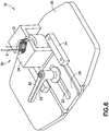
- FIG. 6 is a diagram representing a view of the connector holder assembly 18. Sliding of the sliding plate 28 in the linear groove formed in main plate 20 is facilitated by a pair of slide arms 24 that are attached (e.g., fastened) to the main plate 20 and configured to partly overlie the linear groove along its parallel edges, thereby preventing the sliding plate 28 from being lifted upward and out of the groove.
- the locking handle 82 is rotatably mounted to a bolt that passes through a linear slot 22 formed in the sliding plate 28 and is threadably coupled to the main plate 20.
- the linear slot 22 prevents interference with the bolt as the sliding plate 28 is slid in the linear groove.
- the connector holder assembly 18 further includes a clamp 30 consisting of a first jaw 32 which is fixedly coupled to the main plate 20 and a second jaw 34 which is fixedly coupled to the sliding plate 28.
- a clamp 30 consisting of a first jaw 32 which is fixedly coupled to the main plate 20 and a second jaw 34 which is fixedly coupled to the sliding plate 28.
- the electrical connector 2 (with a wire 6 connected to a contact inserted in one hole) is clamped between the jaws 32 and 34.
- the position of the second jaw 34 is adjustable by moving the sliding plate 28 toward the electrical connector 2 until the second jaw 34 abuts the shell of the electrical connector 2. Then the sliding plate 28 is locked in place by turning the locking handle 82, thereby firmly clamping the shell of the electrical connector 2 and holding the shell in a fixed position relative to the main plate 20.
- the apparatus 10 further includes the following components: an insertion tip 41 having an axis and a distal end configured to contact one end of a contact partially inserted in a hole in the electrical connector 2 while providing clearance for a wire that is terminated by the contact; and associated mechanisms (referred to herein as the "insertion tip displacement assembly") for displacing the insertion tip 41 along a first linear path (in this example, a vertical linear path) that is collinear with the axis of the insertion tip 41.
- the insertion tip displacement assembly includes an insertion arm 38 that is vertically displaceable relative to the housing 14 and projects through a vertical slot formed in the housing 14.
- the insertion tip displacement assembly further includes a quick release pin 42 that passes through a vertical bore in the end of the insertion arm 38 and a quick release button 39 that is attached to the insertion arm 38 and holds the quick release pin 42 in a fixed vertical position relative to the insertion arm 38.
- the insertion tip displacement assembly further includes an insertion tip holder 40 (e.g., in the form of a collar) that holds the insertion tip 41 so that the axis of the insertion tip 41 is parallel with a centerline of the shell of the electrical connector 2 during vertical displacement of the insertion arm 38.
- the components for driving vertical displacement of the insertion arm 38 (which components are described in more detail below) are disposed inside the housing 14 and not visible in FIG 1 .
- the vibration module 44 is configured to generate vibrations in the quick release pin 42.
- the vibration module 44 When activated by the apparatus controller (not shown in FIG. 1 ), the vibration module 44 generates vibrations which propagate down the quick release pin 42 and cause the insertion tip 41 to vibrate.
- This assembly depicted in FIG.1 provides a method to quickly attach and detach the insertion tip 41, provides the ability to apply vibratory forces to the insertion tip 41 to aid in insertion, and provides for the insertion tip 41 to be rotated slightly after being mounted to aid in manipulating the wire 6 into the insertion tip 41.
- FIG. 2 is a diagram representing a view of the apparatus 10 depicted in FIG. 1 , with the difference that an electrical contact at the end of a wire 6 has been manually partially inserted into a hole in the clamped electrical connector 2.
- the vibration module 44 includes a clamp 44a that clamps onto the quick release pin 42 and a vibration motor 44b mounted to the clamp 44a.
- the insertion tip 41 is fixedly coupled to the end of the quick release pin 42 by the insertion tip holder 40.
- Electrical connectors come in many sizes and configurations. This disclosure is concerned with multi-hole electrical connectors which accept a multiplicity of contacts which respectively terminate a multiplicity of wires making up a wire bundle.
- Electrical connector assemblies generally include a plug and a receptacle, each of which contains a dielectric insert that has electrical contacts retained within bores in the inserts. The rear portion of the assembly contains a sealing grommet, through which the wires connected to the contacts pass, and which grommet seals the contacts contained in the insert from moisture.
- the sealing grommet is usable in various electrical connector assemblies wherein contacts are retained within dielectric inserts with the wires leading to said contacts passing through a grommet that seals the connectors from moisture.
- One-half of a connector assembly for use with pin-type (i.e., male) contacts has a contact retaining insert formed of dielectric material, a plurality of pin-type contacts secured within axial holes of the insert, an interfacial seal, a front retaining ring, a connector shell, a retaining nut and a rear retaining nut, with the sealing grommet provided to prevent access to the contacts by moisture from the environment.
- the dielectric insert has a face which contacts the sealing grommet and an opposite face which faces the interfacial seal for the front of the pin-type contacts. Wires lead from the contacts through the sealing grommet.
- the sealing grommet is typically formed of a rubber-type material, such as a silicone rubber or neoprene rubber, has a front face and a rear face, with a plurality of axial passageways therethrough which cooperate and align with the axial holes of the dielectric insert. Each contact occupies a single axial passageway formed in the sealing grommet.
- a rubber-type material such as a silicone rubber or neoprene rubber
- FIG. 17 is a diagram representing a three-dimensional view of a typical insertion tip 41.
- the insertion tip 41 has a circular cylindrical portion 41a that is held by the insertion tip holder 40 (not shown in FIG. 17 , but see FIG. 2 ).
- the insertion tip 41 also has a grooved portion 41b having a C-shaped cross section. The radius of the grooved portion 41b is selected to fit inside the holes of the electrical connector 2 (not shown in FIG. 17 , but see FIG. 2 ).
- the grooved portion 41 b of the insertion tip 41 has a C-shaped or semi-circular end face 45 which abuts a portion of the electrical contact during insertion into the electrical connector 2.
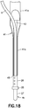
- FIG. 18 is a diagram representing a side view of a portion of a wire 6 pressed into the groove 43 formed in the insertion tip 41 depicted in FIG. 17 .
- An unjacketed end portion of the wire 6 has a pin-type contact 4a (made of metal) crimped thereon.
- the pin-type contact 4a includes a contact pin 27, a locking tab or shoulder 25 (which will be retained by a retainer mechanism inside a hole in the electrical connector 2), and a crimp barrel 26 having indentations where the crimp barrel 26 has been crimped onto the unjacketed end portion of the wire 6.
- a pin-type contact 4a made of metal
- the pin-type contact 4a includes a contact pin 27, a locking tab or shoulder 25 (which will be retained by a retainer mechanism inside a hole in the electrical connector 2), and a crimp barrel 26 having indentations where the crimp barrel 26 has been crimped onto the unjacketed end portion of the wire 6.
- the end face 45 abuts the confronting end face of the crimp barrel 26 and pushes the pin-type contact 4a into a hole in the electrical connector 2.
- the end face 45 of the insertion tip 41 is configured to engage the locking tab or shoulder 25 of the pin-type contact 4a
- FIG. 19 is a diagram representing a cross-sectional view of a typical pin-type contact 4a inserted in a hole formed in a rigid front insulator 8 and in an axial passageway 11 formed in a sealing grommet 7 of an electrical connector 2.
- the sealing grommet 7 and rigid front insulator 9 are both seated inside a shell 3 of the electrical connector 2.
- the pin-type contact 4a protrudes out of the hole 1 in the rigid front insulator 8 when the pin-type contact 4a is in its final position.
- the pin contacts 4a is held in place by resilient fingers (not shown in FIG. 19 that latch behind the locking tab or shoulder 25 of the pin-type contact 4a.
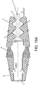
- FIG. 19A is a diagram representing a magnified view of the portion of the assembly inside the oval labeled 19A in FIG. 19 .
- the assembly includes a sealing grommet 7 and a rigid front insulator 9 with a resilient front insulator 8 sandwiched therebetween.
- the axial passageway 11 in the sealing grommet 7 is aligned with the hole 1 in the front insulators.
- the internal surface of each axial passageway 11 has resilient convolutions 5 which enable the use of the sealing grommet 7 with a range of wire gauges, so that the sealing grommet 7 is usable in various connector assemblies without the need for a special grommet for each different wire gauge, while assuring an efficient moisture seal for the contacts.
- FIG. 20 is a diagram representing a cross-sectional view of a socket-type contact 4b inserted in an electrical connector 2.
- the electrical connector for receiving socket-type contacts 4b has components similar to the components seen in FIG. 19 .
- the socket-type contacts 4b do not protrude outside the holes 1 formed in the rigid front insulator 9.
- FIG. 3 is a diagram representing a view of portions of the apparatus 10 depicted in FIG. 1 following removal of the connector holder assembly 18 to reveal a test probe 46 (separated from the insertion tip 41 above by a large gap) and associated mechanisms (referred to herein as the "test probe displacement assembly") for vertically displacing the test probe 46 along a second linear path that is collinear with the axis of the insertion tip 41 and aligned with the first linear path.
- the movements of the test probe 46 and insertion tip 41 are coordinated by a controller 76 which is programmable (see FIG. 13 ).
- the distal end of the insertion tip 41 leads the insertion tip 41 when the insertion tip 41 is displaced in a first direction (e.g., downward), and the distal end of the test probe 46 leads the test probe 46 when the test probe 46 is displaced in a second direction (e.g., upward) opposite to the first direction.
- the test probe 46 has an axis and a distal end configured to contact another end of the contact 4a or 4b after the contact 4a or 4b has been inserted further into a hole in the electrical connector 2 by the insertion tip 41.
- the test probe displacement assembly includes the following components: a rotatable shaft 52; a pair of manually operable activation levers 80 fixedly mounted to opposing ends of the shaft 52; a pinion gear 54 fixedly mounted to the shaft 52 and comprising a multiplicity of teeth; a test probe support shelf 48 which is movable vertically along a linear bearing 36 and to which the test probe 46 is fixedly mounted; a rack 50 affixed to the test probe support shelf 48 and comprising a multiplicity of teeth, at least one tooth on the rack 50 being interengaged with a pair of teeth on the pinion gear 54; and a return block 56 fixedly mounted to the shaft 52.
- the rack 50 and pinion gear 54 convert rotation of shaft 52 into linear displacement of the test probe support shelf 48.
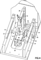
- FIG. 4 is a diagram representing a view of portions of the apparatus depicted in FIG. 3 after the test probe 46 has been displaced upward.
- FIG. 4 shows the test probe 46 separated from the insertion tip 41 above by a small gap; in contrast to FIG. 3 , which shows the test probe 46 in a lower position with a larger gap separating the test probe 46 and the insertion tip 41.
- the apparatus 10 further includes an angular position sensor 78 (e.g., a rotary potentiometer) which is configured and mounted to detect the angular position of the shaft 52. Since the vertical displacement of the test probe 46 is directly proportional to the degree of rotation of the shaft 52, the angular position sensor 78 outputs electrical signals that represent the vertical position of the test probe 46 relative to the frame of reference of the base 12. The angular position sensor 78 senses the position of the test probe 46 and outputs signals representing the position of the test probe to a controller 76 (see FIG. 13 ) for processing the sensor data.
- a controller 76 see FIG. 13
- the controller 76 is configured to cause the insertion tip displacement assembly to displace the insertion tip 41 along the first linear path in the first direction during a first portion of a time cycle and later cause the test probe displacement assembly to displace the test probe 46 along the second linear path in the second direction during a second portion of the time cycle.
- the apparatus is also configured to output display control signals to a human-machine interface 74 indicating error states or successful retention based on shaft angular position data received from the angular position sensor 78. In response to receipt of such display control signals from the controller 76, the human-machine interface 74 displays symbology indicating error states or successful retention to the operator.
- FIG. 5 is a diagram representing a view of the human-machine interface 74 of the apparatus 10 depicted in FIG. 1 . This implementation of the human-machine interface 74 is a touch-screen liquid-crystal display device.
- both the insertion tip displacement assembly and the test probe displacement assembly include pneumatic cylinders 58, 60, 70 and 72 for driving the respective displacements in either direction.
- the pneumatic cylinders are connected to electrically controlled pneumatic valves 66 (e.g., solenoid valves) which are selectively activated by the controller 76, which sends electrical valve control signals to control the states of the pneumatic valves 66.
- pneumatic valves 66 e.g., solenoid valves
- the insertion tip displacement assembly includes the following additional components: an insertion cylinder 70 (having a piston 88 connected to a piston rod 90) that causes the insertion arm 38 to displace in the first direction with the insertion tip 41 displacing along the first linear path (in the first direction) in response to activation of the insertion cylinder 70 and a first return cylinder 72 (having a piston 92 connected to a piston rod 94) that causes the insertion arm 38 to displace in the second direction with the insertion tip 41 displacing along the first linear path (in the second direction) in response to activation of the first return cylinder 72.
- an insertion cylinder 70 having a piston 88 connected to a piston rod 90
- a first return cylinder 72 having a piston 92 connected to a piston rod 94
- test probe displacement assembly includes the following additional components: a test cylinder 58 (having a piston 84 connected to a piston rod 86) that causes the test probe support shelf 48 to displace in the second direction with the test probe 46 displacing along the second linear path (in the second direction) in response to activation of the test cylinder 58 and a second return cylinder 60 (having a piston 62 connected to a piston rod 64) that causes the test probe support shelf 48 to displace in the first direction with the test probe 46 displacing along the second linear path (in the first direction) in response to activation of the second return cylinder 60.
- a test cylinder 58 having a piston 84 connected to a piston rod 86
- second return cylinder 60 having a piston 62 connected to a piston rod 64
- test cylinder 58 and the test probe support shelf 48 are arranged so that the test probe support shelf 48 is contacted by and displaced in a direction parallel to the second direction by one end of the piston rod 86 of the test cylinder 58 when the test cylinder 58 is activated, but is not attached to the one end of the piston rod 86 of the test cylinder 58.
- This upward vertical displacement of the test probe support shelf 48 in turn raises the test probe 46, which is affixed to the test probe support shelf 48.
- the return block 56 (seen in FIGS.
- FIG. 7 is a diagram representing a side view of the apparatus depicted in FIG. 1 with the left-side cover open to reveal the pressure regulators and gauges inside the housing 14.
- Each pneumatic cylinder is operatively coupled to a pressure regulator 66 by way of a respective pneumatic valve and a respective flexible hose (not shown in the drawings).
- the pressure regulator 66 regulates (i.e., reduces) the pressure of the compressed air being supplied via tubing from a main air supply (not shown in the drawings).
- the controller 76 also controls activation of the vibration module 44 (see FIGS. 1 and 7 ).
- the controller 76 activates the vibration module 44 in response to data from the angular position sensor 78 indicating that the contact being inserted was not fully inserted. More specifically, the controller 76 is configured to activate the vibration module 44 if the test probe 46 does not displace along the second linear path in the first direction by at least a specified distance during displacement of the insertion tip 41 along the first linear path in the first direction. For example, this occur if the contact was inserted in the correct hole but did not reach a position whereat the contact could be retained by the retention mechanism (e.g., spring fingers or a retention clip) inside the hole.
- the retention mechanism e.g., spring fingers or a retention clip
- the contact 4a or 4b is inserted in the wrong hole while the test probe 46 is inserted in the correct hole.
- the test probe 46 will not move in the first direction when the insertion tip 41 is moved in the first direction because the contact being pushed downward by the insertion tip 41 does not impinge upon the test probe 46, which is in a neighboring hole.
- the controller 76 is further configured to generate an error signal if the test probe 46 does not displace along the second linear path in the first direction by at least a specified distance during displacement of the insertion tip 41 along the first linear path in the first direction.
- the controller 76 is configured to cause the test probe displacement assembly to displace the test probe 46 along the second linear path in the second direction during a second portion of the time cycle for the purpose of testing the retention of an inserted contact.
- the test probe displacement assembly namely, the test cylinder 58
- the controller 76 is further configured to generate an error signal if the test probe 46 displaces along the second linear path in the second direction by more than a specified distance in response to application of force by the test cylinder 58. Upward displacement by more than the specified distance indicates that the pin- or socket-type contact (which is abutting the distal end of the test probe 46) is not being retained inside the hole 1 in the electrical connector 2.
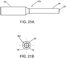
- FIGS. 21A and 21B are diagrams representing side and end views respectively of a pin-type test probe 46a (for use in inserting a pin-type contact 4a of the type depicted in FIG. 19 ) in accordance with one embodiment.
- the pin-type test probe 46a has a shank 98 and a distal end 96 with a flat end face 23 that is designed to abut and push against the end of the pin-type contact 4a.
- the distal end 96 of pin-type test probe 46a has a diameter less than the diameter of the shank 98.
- FIGS. 22A and 22B are diagrams representing side and end views respectively of a socket-type test probe 46b (for use in inserting a socket-type contact 4b of the type depicted in FIG. 20 ) in accordance with one embodiment.
- the socket-type test probe 46b has a shank 98 and a round distal end 95 with a flat end face that is designed to be partially inserted into and push against the end of the socket-type contact 4a.
- the flat end face is circular with a diameter less than the diameter of the opening in the socket-type contact 4a.
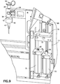
- FIG. 9 is a diagram representing a side view of portions of the apparatus 10 depicted in FIG. 1 with the right-side cover open and the connector holder assembly 18 removed.
- This view shows a linear guide rail 68 disposed inside the housing. More specifically, the linear guide rail 68 is disposed vertically and guides vertical displacement of an insertion arm displacement plate 75 to which the insertion arm 38 is affixed.
- the apparatus further includes linear bearings that enable the insertion arm displacement plate 75 to travel smoothly along the guide rail 68 in response to activation of the one of the insertion cylinder 70 and first return cylinder 72.
- the smaller channel to the right of the linear guide rail 68 in FIG. 9 is a linear displacement transducer 71 that directly measures the vertical position (elevation) of the insert arm 38. More specifically, the linear displacement transducer 71 senses a position of a component (e.g., insertion arm displacement plate 75) of the insertion tip displacement assembly that has a fixed positional relationship relative to the insertion tip 41 and outputs signals representing the position of the insertion tip 41 to the controller 76.
- a component e.g., insertion arm displacement plate 75
- the linear displacement transducer 71 is used to unlock a "hold up" function of the insert arm 38 which happens at the end of a complete cycle.
- the insert arm 38 is raised at the end of a cycle and held there until it is manually lifted above a threshold position. This tells the controller 76 to cause the first return cylinder 72 to lower the piston rod 94. This gives the operator the ability to freely load contacts and manipulate the electrical connector 2 without the insert tip 41 getting in the way.
- the linear displacement transducer 71 is useful for other purposes. For example, by noting the position of the insertion arm 38 as the tool inserts the contact in relation to insert time, in one proposed implementation the controller 76 is configured to determine if the contact is sticking and use that information to trigger warnings and also turn on the vibratory system. Another potential use case is to create "insertion graphs" of movement versus time which is displayed on the screen of the human-machine interface 74 and used as both a troubleshooting and a feedback mechanism for illustrating problem insertion cycles. In addition, the position information provided by the linear displacement transducer 71 enables calculation of the movement speed for the purposes of calibrating the machine for consistent operation and helping to detect maintenance issues.
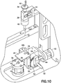
- FIG. 10 is a diagram representing a view of portions of the apparatus 10 for automated insertion and testing of electrical contacts in a state wherein an insertion tip 41 and a test probe 46 are separated by a large gap.
- the test probe is a socket-type test probe 46b.
- FIG. 10 provides a more advantageous view of the components of the test probe displacement assembly which cause the test probe support shelf 48 to displace downward in response to activation of the second return cylinder 60.
- the piston rod 64 is extended.
- the end of the piston rod 64 pushes against the return block 56, thereby causing the shaft 52 to rotate.
- FIG. 11 is a flowchart identifying steps of a method 100 for inserting a contact in an electrical connector and then testing for contact retention.
- the angular position sensor 78 monitors the position of the test probe 46 at any time during the contact insertion and retention testing operations.
- the controller 76 receives feedback from the angular position sensor 78 during these operations and then applies logic to the sensor data to trigger certain actions. For example, the controller 76 determines if an error has occurred or, in the alternative, if insertion was successful in the sense that the inserted contact is being retained with a retention force greater than the testing force being exerted on the contact by the test probe 46.
- the method 100 includes the following steps.
- the electrical connector 2 is loaded in the connector holder assembly 18 (step 102).
- the connector holder assembly 18 is loaded into the slots underneath the lift-restricting arms 16 (step 104).
- the position of the main plate 20 is coarsely adjustable so that the electrical connector 2 is underneath the insertion tip 41.
- the contact is manually inserted in the insertion tip 106 by the operator (step 106).
- the insert arm 38 is lowered until the contact is partially inserted in a selected hole 1 in the electrical connector 2 (step 108).
- the position of the main plate 20 is finely adjustable so that the selected hole 1 in the electrical connector 2 is directly below the contact carried by the insertion tip 41.
- the mechanical components that make up the test probe mount and actuating mechanism provide adequate friction to hold the end face 23 of the test probe 46 at the starting position during tool activation.
- the primary sources of this friction is the angular position sensor 78 (e.g., rotary potentiometer), the solid bushings on opposing ends of the shaft 52, and the linear bearing (not shown in the drawings) which enables the test probe support shelf 48 to displace vertically.
- FIG. 12 is a diagram indicating various vertical positions A through F of the end face 23 of the test probe 46 during one test cycle.
- the lowermost horizontal line represents the zero position F of the end face 23 when the machine is reset (for example, by activation of the second return cylinder 60).
- the uppermost horizontal line represents the starting position A after the test probe 46 has been displaced vertically upward by the test cylinder 58.
- the next horizontal line represents a vertical position B corresponding to the alignment check point (explained in more detail below).
- the next horizontal line represents a vertical position C corresponding to the vibration check point (explained in more detail below).
- the next horizontal line represents a vertical position D corresponding to the insertion failure point (explained in more detail below).
- the dashed horizontal line represents a vertical position E corresponding to the position of the tip of the fully inserted contact and the position of the abutting end face 23 of the test probe 46.
- the controller 76 determines whether the end face 23 of the test probe 46 is in the starting position A (see FIG. 12 ) based on the sensor feedback being received from the angular position sensor 78 or not (step 112). On the one hand, if the controller 76 determines in step 112 that the end face 23 of the test probe 46 is not in the starting position A, then the automated cycle is not initiated and an error message is displayed by the human- machine interface 74, indicating that the operator should troubleshoot the problem and then try again (step 114).
- step 112 determines in step 112 that the end face 23 of the test probe 46 is in the starting position A, then the controller 76 activates the insertion cylinder 70, causing the insertion arm to move downward, thereby inserting the contact further into the selected hole 1 (step 116).
- the controller 76 determines whether the end face 23 of the test probe 46 has moved below the alignment check point at vertical position B (see FIG. 12 ) based on the sensor feedback being received from the angular position sensor 78 or not (step 118). On the one hand, if the controller 76 determines in step 118 that the end face 23 of the test probe 46 has not moved below the alignment check point, then the machine is reset by activating the first return cylinder 72 and an error message is displayed by the human-machine interface 74, indicating to the operator that the contact and the test probe 46 are not in the same hole (step 120).
- step 118 determines whether the end face 23 of the test probe 46 has moved below the alignment check point
- the controller 76 determines whether the end face 23 of the test probe 46 has moved below the vibration check point at vertical position C (see FIG. 12 ) based on the sensor feedback being received from the angular position sensor 78 or not (step 122).
- step 122 determines in step 122 that the end face 23 of the test probe 46 has not moved below the vibration check point
- the vibration motor 44b is activated (step 124) and an error message is displayed by the human-machine interface 74, warning the operator to check the insertion pin (step 126) when the vibration cycle has ceased.
- step 122 determines in step 122 that the end face 23 of the test probe 46 has moved below the vibration check point
- the controller 76 deactivates the insertion cylinder 70 to release the downward force being exerted on the insertion tip 41 and then initiates the retention test by activating the test cylinder 58 to apply a force that pushes the test probe upward (steps 128), which applied force is less than the specified minimum retention force for the contact.
- the controller 76 determines whether the end face 23 of the test probe 46 has moved from below to above the insertion failure point at vertical position D (see FIG. 12 ) based on the sensor feedback being received from the angular position sensor 78 or not (step 130). On the one hand, if the controller 76 determines in step 130 that the end of the test probe 46 has moved above the insertion failure point, then the machine is reset by activating the first return cylinder 72 and an error message is displayed by the human-machine interface 74 (step 132), indicating to the operator that contact insertion has failed.
- step 130 determines in step 130 that the end of the test probe 46 has not moved above the insertion failure point
- the controller 76 instructs the human-machine interface 74 to display a message indicating that contact insertion was successful, at which point the retention test cycle automatically ends.
- FIG. 14 is a diagram representing a view of the same components seen in FIG. 1 , except that the connector holder assembly 18 has been removed. Elements in FIG. 14 which bear the same reference numerals as those appearing in FIG. 1 have the same functionality as the corresponding element in FIG. 1 , which functionality has been described above and will not be repeated here.
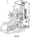
- FIG. 15 is a diagram representing a cut-away view showing some internal components of the apparatus depicted in FIG. 14 , including a test probe gear system 49 in the form of a rack 50 and a pinion gear 54.
- FIG. 16 is a diagram representing an orthographic view of a connector holder assembly 18 in accordance with an alternative embodiment.
- the connector holder assembly 18 includes a clamp 30 consisting of a first jaw 32 which is fixedly coupled to the main plate 20 and a second jaw 34 which is fixedly coupled to the sliding plate 28.
- the electrical connector 2 is clamped between the jaws 32 and 34.
- the position of the second jaw 34 is adjustable by moving the sliding plate 28 toward the electrical connector 2 until the second jaw 34 abuts the shell of the electrical connector 2.
- a pair of slide arms 24 are attached to the main plate 20 to prevent the sliding plate 28 from lifting upward out of the groove in which the sliding plate 28 slides.
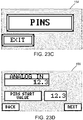
- FIGS. 23A through 23D are diagrams representing respective example screenshots displayed on the human-machine interface 74 of the apparatus 10 depicted in FIG. 1 .
- FIG. 23A shows a screenshot 150 wherein the operator starts the system by touching the virtual button named "SYSTEM START".
- FIG. 23B shows the main operating screen 152. Not all of the fields shown in FIG. 23B are displayed at the same time. The symbol "?" is a warning to manually check the contact. The warnings only appear if the corresponding event has happened. The data on the side is displayed only in a data display mode.
- FIG. 23C shows a pins/socket selection screen 154. By pressing the main virtual button, the operator can toggle between selecting a program for pin-type contacts and selecting a program for socket-type contacts.
- FIG. 23D shows a typical maintenance screen 156 for adjusting test and error values.
- Computer numerical control is the automation of machine tools by means of computers executing pre-programmed sequences of machine control commands.
- Some steps of the methods described herein are encoded as executable instructions embodied in a non-transitory tangible computer-readable storage medium, including, without limitation, a storage device and/or a memory device. Such instructions, when executed by a CNC controller, cause the apparatus to perform at least a portion of the methods described herein.
- controller means a computer or processor configured to execute pre-programmed sequences of machine control commands for controlling computer-controlled components of the contact insertion and retention testing apparatus disclosed herein.
- Such devices typically include a processor, processing device, or controller, such as a general-purpose central processing unit, a microcontroller, a reduced instruction set computer processor, an ASIC, a programmable logic circuit, an FPGA, a digital signal processor, and/or any other circuit or processing device capable of executing the functions described herein.
- the methods described herein may be encoded as executable instructions embodied in a non-transitory tangible computer-readable storage medium, including, without limitation, a storage device and/or a memory device. Such instructions, when executed by a processing device, cause the processing device to perform at least a portion of the methods described herein.
- the above examples are exemplary only, and thus are not intended to limit in any way the definition and/or meaning of the terms "processor” and "computing device”.
Landscapes
- Physics & Mathematics (AREA)
- General Physics & Mathematics (AREA)
- Engineering & Computer Science (AREA)
- Manufacturing & Machinery (AREA)
- Manufacturing Of Electrical Connectors (AREA)
- Measuring Leads Or Probes (AREA)
Applications Claiming Priority (2)
| Application Number | Priority Date | Filing Date | Title |
|---|---|---|---|
| US201862670343P | 2018-05-11 | 2018-05-11 | |
| US16/224,853 US11128086B2 (en) | 2018-05-11 | 2018-12-19 | Apparatus for contact insertion and retention testing |
Publications (3)
| Publication Number | Publication Date |
|---|---|
| EP3591771A2 true EP3591771A2 (de) | 2020-01-08 |
| EP3591771A3 EP3591771A3 (de) | 2020-02-12 |
| EP3591771B1 EP3591771B1 (de) | 2025-07-02 |
Family
ID=68463361
Family Applications (1)
| Application Number | Title | Priority Date | Filing Date |
|---|---|---|---|
| EP19174225.3A Active EP3591771B1 (de) | 2018-05-11 | 2019-05-13 | Vorrichtung und verfahren zur kontakteinführungs- und -halteprüfung |
Country Status (4)
| Country | Link |
|---|---|
| US (2) | US11128086B2 (de) |
| EP (1) | EP3591771B1 (de) |
| JP (1) | JP7319065B2 (de) |
| CN (1) | CN110470866B (de) |
Cited By (1)
| Publication number | Priority date | Publication date | Assignee | Title |
|---|---|---|---|---|
| CN113588015A (zh) * | 2021-09-29 | 2021-11-02 | 常州诺德电子股份有限公司 | 连接器端子装配防退针工装和方法 |
Families Citing this family (13)
| Publication number | Priority date | Publication date | Assignee | Title |
|---|---|---|---|---|
| US11128086B2 (en) * | 2018-05-11 | 2021-09-21 | The Boeing Company | Apparatus for contact insertion and retention testing |
| EP3757536A1 (de) * | 2019-06-25 | 2020-12-30 | Kistler Holding AG | Kontaktkraftmessvorrichtung und verfahren zum messen einer kontaktkraft mit einer solchen kontaktkraftmessvorrichtung |
| CN111596368B (zh) * | 2020-05-28 | 2025-08-19 | 广东科世得润汽车部件有限公司 | 汽车车身线束测试台 |
| US11592476B2 (en) * | 2020-09-17 | 2023-02-28 | Maury Microwave, Inc. | Impedance tuners with linear actuators |
| GB2616076B (en) * | 2022-02-28 | 2024-04-10 | Aptiv Tech Ltd | Plugging force test apparatus |
| CN115950569A (zh) * | 2022-12-28 | 2023-04-11 | 大连理工大学 | 一种电连接器接触件保持力检测装置及方法 |
| CN116298431B (zh) * | 2023-05-19 | 2023-08-04 | 山东天鲲电力科技有限公司 | 一种sf6充气柜测试用压力可控式检测装置 |
| CN117192190B (zh) * | 2023-11-08 | 2024-01-12 | 深圳市力容电子有限公司 | 一种电容器电压检测设备和检测方法 |
| GB2639837A (en) * | 2024-03-22 | 2025-10-08 | Fokker Elmo B V | End effector, apparatus and methods for multi-pin electrical connectors |
| CN118431867B (zh) * | 2024-05-16 | 2024-11-08 | 深圳市紘通电子有限公司 | 一种用于连接器的装配组件及其装配方法 |
| CN118801194B (zh) * | 2024-09-11 | 2025-01-21 | 顺科智连技术股份有限公司 | 一种带屏蔽的加热插头生产装置 |
| CN119643123B (zh) * | 2024-12-11 | 2026-01-27 | 中国计量大学 | 连接器的接触件的保持力测试装置 |
| CN120281272B (zh) * | 2025-04-07 | 2025-09-23 | 安徽旭合新能源科技有限公司 | 一种0bb电池iv特性测试装置 |
Citations (1)
| Publication number | Priority date | Publication date | Assignee | Title |
|---|---|---|---|---|
| US5689191A (en) * | 1995-04-13 | 1997-11-18 | Yazaki Corporation | Terminal-in-connector checking device |
Family Cites Families (53)
| Publication number | Priority date | Publication date | Assignee | Title |
|---|---|---|---|---|
| US2292236A (en) * | 1941-01-14 | 1942-08-04 | Carl P Martin | Prod |
| US2535988A (en) * | 1949-10-18 | 1950-12-26 | Jacob B Lew | Tension testing apparatus for electric sockets and wire connections |
| JPS5318545Y2 (de) * | 1972-03-22 | 1978-05-17 | ||
| US4241967A (en) | 1979-08-31 | 1980-12-30 | The Bendix Corporation | Electrical connector assembly sealing grommet |
| JPH0620314Y2 (ja) | 1987-08-10 | 1994-05-25 | 住友電装株式会社 | 端子挿入検査器 |
| US4981446A (en) | 1989-11-06 | 1991-01-01 | The Boeing Company | Modular, circular, environment resistant electrical connector assembly |
| US5099572A (en) | 1989-11-06 | 1992-03-31 | The Boeing Company | Method of assembling an electrical connector assembly |
| US5183413A (en) | 1989-12-21 | 1993-02-02 | The Boeing Company | Modular, circular, environment resistant electrical connector assembly having retention clips for manually or automatically loading of electrical contacts |
| JP2507480Y2 (ja) * | 1991-07-23 | 1996-08-14 | 日本航空電子工業株式会社 | コンタクト挿入装置 |
| JP2575406Y2 (ja) * | 1993-08-24 | 1998-06-25 | 住友電装株式会社 | コネクタ検査装置 |
| JP2797928B2 (ja) * | 1993-10-15 | 1998-09-17 | 住友電装株式会社 | コネクタ検査装置 |
| US5614820A (en) * | 1994-03-10 | 1997-03-25 | Sumitomo Wiring Systems, Ltd. | Connector examination device for determining a connection in a connector |
| JPH07333283A (ja) * | 1994-06-13 | 1995-12-22 | Sumitomo Wiring Syst Ltd | 防水型コネクタの検査装置 |
| FR2731301B1 (fr) | 1995-03-03 | 1998-09-11 | Amp France | Machine pour inserer des bornes de conducteurs dans des boitiers de connecteurs |
| US5989065A (en) | 1995-05-05 | 1999-11-23 | The Boeing Company | High performance Mil-C-26500 |
| US6048229A (en) | 1995-05-05 | 2000-04-11 | The Boeing Company | Environmentally resistant EMI rectangular connector having modular and bayonet coupling property |
| JP3247031B2 (ja) * | 1995-06-16 | 2002-01-15 | 矢崎総業株式会社 | コネクタ試験器 |
| JP3161351B2 (ja) * | 1997-02-24 | 2001-04-25 | 住友電装株式会社 | オートロック式導通検査ユニット |
| KR100277728B1 (ko) * | 1997-03-13 | 2001-01-15 | 윤종용 | 인쇄회로기판 검사장치 |
| US6359452B1 (en) * | 1998-07-22 | 2002-03-19 | Nortel Networks Limited | Method and apparatus for testing an electronic assembly |
| EP1209778B1 (de) * | 1999-07-28 | 2004-10-06 | Sumitomo Wiring Systems, Ltd. | Inspektionsapparat und Inspektionsverfahren für die Drahtmontage |
| JP2002008762A (ja) | 2000-06-26 | 2002-01-11 | Smk Corp | 電源接続用コネクタ |
| US6731118B2 (en) * | 2001-06-07 | 2004-05-04 | Sumitomo Wiring System Ltd. | Connector inspection apparatus |
| JP3750649B2 (ja) | 2001-12-25 | 2006-03-01 | 住友電気工業株式会社 | 光通信装置 |
| JP4093828B2 (ja) * | 2002-08-29 | 2008-06-04 | 松下電器産業株式会社 | 測定用プローブ及び光学式測定装置 |
| US7342402B2 (en) * | 2003-04-10 | 2008-03-11 | Formfactor, Inc. | Method of probing a device using captured image of probe structure in which probe tips comprise alignment features |
| US7511505B1 (en) * | 2003-12-17 | 2009-03-31 | Heatcraft Refrigeration Products Llc | Centralized connector module having component diagnostic capability, refrigeration unit incorporating the same and methods of assembling and troubleshooting a refrigeration unit |
| US7301356B2 (en) * | 2004-10-28 | 2007-11-27 | Hewlett-Packard Development Company, L.P. | Support for a receptacle block of a unit under test |
| US7128618B1 (en) * | 2005-06-09 | 2006-10-31 | Yazaki North America, Inc. | Connector check fixture |
| KR100695816B1 (ko) * | 2005-07-29 | 2007-03-19 | 삼성전자주식회사 | 이디에스 설비의 포고 핀 검사 장치 |
| US7698809B2 (en) * | 2006-05-12 | 2010-04-20 | Tyco Electronics Corporation | Apparatus and method for detecting a location of conductive pins with respect to a circuit board |
| US8375804B2 (en) * | 2009-05-15 | 2013-02-19 | VISWELL Technology Co., Ltd. | Apparatus for testing bonding strength of electrical connections and frictionless calibration device for the same |
| US8096038B2 (en) | 2007-05-11 | 2012-01-17 | The Boeing Company | Robotic end effector and clamping method |
| JP2009128216A (ja) * | 2007-11-26 | 2009-06-11 | Yazaki Corp | 導通検査治具、該導通検査治具を備えた導通検査装置、及び導通検査方法 |
| US8099857B2 (en) * | 2008-02-09 | 2012-01-24 | Cirris Systems Corporation | Apparatus for electrical pin installation and retention confirmation |
| US7819035B2 (en) * | 2008-04-14 | 2010-10-26 | Ge Inspection Technologies, Lp | Detachable, quick disconnect system for nondestructive testing components |
| DE102008048081B4 (de) * | 2008-09-19 | 2015-06-18 | Cascade Microtech, Inc. | Verfahren zur Prüfung elektronischer Bauelemente einer Wiederholstruktur unter definierten thermischen Bedingungen |
| US8604801B2 (en) * | 2009-04-21 | 2013-12-10 | General Instrument Corporation | Connector fitting test tool |
| JP5326893B2 (ja) | 2009-07-15 | 2013-10-30 | 住友電装株式会社 | 端子挿入装置 |
| CN101656365B (zh) * | 2009-08-28 | 2012-06-20 | 中航光电科技股份有限公司 | 一种方便测试的电连接器 |
| JP5566212B2 (ja) * | 2010-07-20 | 2014-08-06 | 矢崎総業株式会社 | 導通検査治具 |
| JP4859261B1 (ja) * | 2010-10-20 | 2012-01-25 | 日本航空電子工業株式会社 | 基板用コネクタ |
| US9395400B1 (en) * | 2013-03-11 | 2016-07-19 | Amazon Technologies, Inc. | Test fixture to test device connectors |
| US9263840B1 (en) * | 2013-03-20 | 2016-02-16 | The Boeing Company | Self-monitoring electrical contact insertion tool |
| US9300104B1 (en) | 2013-03-20 | 2016-03-29 | The Boeing Company | Electrical contact insertion tool |
| JP2015053207A (ja) * | 2013-09-09 | 2015-03-19 | タイコエレクトロニクスジャパン合同会社 | レバー式電気コネクタ、及び、嵌合システム |
| DE102013221996A1 (de) | 2013-10-29 | 2015-05-21 | Leoni Bordnetz-Systeme Gmbh | Prüfvorrichtung sowie Verfahren zur Überprüfung der positionsrichtigen Belegung eines Kontaktträgers mit elektrischen Kontaktelementen |
| US9863996B2 (en) * | 2013-12-12 | 2018-01-09 | Carlos Gutierrez Martinez | Apparatus and process for testing and improving electrical and/or mechanical characteristics of an electrical connection |
| US10168356B2 (en) * | 2015-08-19 | 2019-01-01 | Tektronix, Inc. | Test and measurement probe with adjustable test point contact |
| US10109974B2 (en) * | 2016-01-29 | 2018-10-23 | The Boeing Company | Vibrating pallet system for automated wire insertion |
| US10082447B2 (en) * | 2016-03-11 | 2018-09-25 | The Boeing Company | System and method to test a contact of a connector |
| CN106410570B (zh) * | 2016-11-11 | 2019-02-15 | 深圳市顺科线束设备有限公司 | 连接器端子自动插入胶壳设备及其加工方法 |
| US11128086B2 (en) * | 2018-05-11 | 2021-09-21 | The Boeing Company | Apparatus for contact insertion and retention testing |
-
2018
- 2018-12-19 US US16/224,853 patent/US11128086B2/en active Active
-
2019
- 2019-03-13 JP JP2019045713A patent/JP7319065B2/ja active Active
- 2019-04-25 CN CN201910338493.2A patent/CN110470866B/zh active Active
- 2019-05-13 EP EP19174225.3A patent/EP3591771B1/de active Active
-
2021
- 2021-08-27 US US17/459,859 patent/US11791587B2/en active Active
Patent Citations (1)
| Publication number | Priority date | Publication date | Assignee | Title |
|---|---|---|---|---|
| US5689191A (en) * | 1995-04-13 | 1997-11-18 | Yazaki Corporation | Terminal-in-connector checking device |
Cited By (2)
| Publication number | Priority date | Publication date | Assignee | Title |
|---|---|---|---|---|
| CN113588015A (zh) * | 2021-09-29 | 2021-11-02 | 常州诺德电子股份有限公司 | 连接器端子装配防退针工装和方法 |
| CN113588015B (zh) * | 2021-09-29 | 2022-02-15 | 常州诺德电子股份有限公司 | 连接器端子装配防退针工装和方法 |
Also Published As
| Publication number | Publication date |
|---|---|
| US11791587B2 (en) | 2023-10-17 |
| CN110470866B (zh) | 2024-04-09 |
| US20210391667A1 (en) | 2021-12-16 |
| EP3591771B1 (de) | 2025-07-02 |
| US20190348794A1 (en) | 2019-11-14 |
| EP3591771A3 (de) | 2020-02-12 |
| CN110470866A (zh) | 2019-11-19 |
| JP7319065B2 (ja) | 2023-08-01 |
| JP2019197720A (ja) | 2019-11-14 |
| US11128086B2 (en) | 2021-09-21 |
Similar Documents
| Publication | Publication Date | Title |
|---|---|---|
| US11791587B2 (en) | Apparatus and methods for contact insertion and retention testing | |
| WO2015156793A1 (en) | Automatic terminated wire lead insertion machine and method of operating said machine | |
| JP7004939B1 (ja) | 電子機器組立装置および電子機器組立方法 | |
| US11817235B2 (en) | Device and method for the automatic assembly of a pair of wires | |
| CN110873667A (zh) | 弯折性能测试装置及弯折性能测试方法 | |
| US12191619B2 (en) | Method, system, and computer program product for wire connector assembly | |
| CN202711652U (zh) | 显示装置检测系统 | |
| CN113640696B (zh) | 一种服务器psu自动化插拔测试系统 | |
| US7698801B2 (en) | Wire-processing device and method of operating such a wire-processing device | |
| KR101574053B1 (ko) | 컨넥터 테스트장치 | |
| US10877106B2 (en) | Conduction inspection jig and inspection method of conduction pin | |
| EP4285449B1 (de) | Crimpvorrichtung für elektrische anschlussklemmen zur verhinderung der entfernung von fehlerhaften crimps | |
| KR101264875B1 (ko) | 차량용 케이블의 커넥터 검사를 위한 지그 | |
| WO2020184679A1 (ja) | 導通検査装置及び導通検査方法 | |
| Sun et al. | Robotic wiring harness assembly system for fault-tolerant electric connectors mating | |
| US20220368096A1 (en) | Device, method and system for assembly of an electrical plug connector | |
| RU2735491C1 (ru) | Способ испытания защитных шторок розеток | |
| WO2021199514A1 (ja) | 検査装置およびワイヤハーネス製造装置 | |
| US20260092768A1 (en) | Measuring Machine Quill Interface | |
| TR2024003704A2 (tr) | Di̇nami̇k deformasyon yoluyla elektri̇k bağlanti elemanlarindaki̇ i̇letkenleri̇n kali̇brasyonu maki̇nesi̇ | |
| JP2024154881A (ja) | 検査方法および把持治具 | |
| JP2023140452A (ja) | コネクタ検査治具、コネクタ検査システムおよびコネクタ検査方法 | |
| JP3710879B2 (ja) | 板材加工装置の板材クランプ装置 | |
| JP2024158764A (ja) | 検査方法 | |
| JPH08250252A (ja) | コネクタ検査装置 |
Legal Events
| Date | Code | Title | Description |
|---|---|---|---|
| PUAI | Public reference made under article 153(3) epc to a published international application that has entered the european phase |
Free format text: ORIGINAL CODE: 0009012 |
|
| STAA | Information on the status of an ep patent application or granted ep patent |
Free format text: STATUS: REQUEST FOR EXAMINATION WAS MADE |
|
| 17P | Request for examination filed |
Effective date: 20190513 |
|
| AK | Designated contracting states |
Kind code of ref document: A2 Designated state(s): AL AT BE BG CH CY CZ DE DK EE ES FI FR GB GR HR HU IE IS IT LI LT LU LV MC MK MT NL NO PL PT RO RS SE SI SK SM TR |
|
| AX | Request for extension of the european patent |
Extension state: BA ME |
|
| PUAL | Search report despatched |
Free format text: ORIGINAL CODE: 0009013 |
|
| AK | Designated contracting states |
Kind code of ref document: A3 Designated state(s): AL AT BE BG CH CY CZ DE DK EE ES FI FR GB GR HR HU IE IS IT LI LT LU LV MC MK MT NL NO PL PT RO RS SE SI SK SM TR |
|
| AX | Request for extension of the european patent |
Extension state: BA ME |
|
| RIC1 | Information provided on ipc code assigned before grant |
Ipc: H01R 43/20 20060101AFI20200108BHEP Ipc: G01R 31/04 20060101ALI20200108BHEP Ipc: G01R 1/073 20060101ALI20200108BHEP |
|
| STAA | Information on the status of an ep patent application or granted ep patent |
Free format text: STATUS: EXAMINATION IS IN PROGRESS |
|
| 17Q | First examination report despatched |
Effective date: 20210422 |
|
| RAP3 | Party data changed (applicant data changed or rights of an application transferred) |
Owner name: THE BOEING COMPANY |
|
| REG | Reference to a national code |
Ref country code: DE Ref legal event code: R079 Free format text: PREVIOUS MAIN CLASS: H01R0043200000 Ipc: G01R0031690000 Ref country code: DE Ref legal event code: R079 Ref document number: 602019071854 Country of ref document: DE Free format text: PREVIOUS MAIN CLASS: H01R0043200000 Ipc: G01R0031690000 |
|
| GRAP | Despatch of communication of intention to grant a patent |
Free format text: ORIGINAL CODE: EPIDOSNIGR1 |
|
| STAA | Information on the status of an ep patent application or granted ep patent |
Free format text: STATUS: GRANT OF PATENT IS INTENDED |
|
| RIC1 | Information provided on ipc code assigned before grant |
Ipc: H01R 43/20 20060101ALI20241004BHEP Ipc: G01R 31/69 20200101AFI20241004BHEP |
|
| INTG | Intention to grant announced |
Effective date: 20241018 |
|
| GRAJ | Information related to disapproval of communication of intention to grant by the applicant or resumption of examination proceedings by the epo deleted |
Free format text: ORIGINAL CODE: EPIDOSDIGR1 |
|
| STAA | Information on the status of an ep patent application or granted ep patent |
Free format text: STATUS: EXAMINATION IS IN PROGRESS |
|
| GRAP | Despatch of communication of intention to grant a patent |
Free format text: ORIGINAL CODE: EPIDOSNIGR1 |
|
| STAA | Information on the status of an ep patent application or granted ep patent |
Free format text: STATUS: GRANT OF PATENT IS INTENDED |
|
| INTC | Intention to grant announced (deleted) | ||
| INTG | Intention to grant announced |
Effective date: 20250303 |
|
| GRAS | Grant fee paid |
Free format text: ORIGINAL CODE: EPIDOSNIGR3 |
|
| P01 | Opt-out of the competence of the unified patent court (upc) registered |
Free format text: CASE NUMBER: APP_18634/2025 Effective date: 20250416 |
|
| GRAA | (expected) grant |
Free format text: ORIGINAL CODE: 0009210 |
|
| STAA | Information on the status of an ep patent application or granted ep patent |
Free format text: STATUS: THE PATENT HAS BEEN GRANTED |
|
| AK | Designated contracting states |
Kind code of ref document: B1 Designated state(s): AL AT BE BG CH CY CZ DE DK EE ES FI FR GB GR HR HU IE IS IT LI LT LU LV MC MK MT NL NO PL PT RO RS SE SI SK SM TR |
|
| REG | Reference to a national code |
Ref country code: GB Ref legal event code: FG4D |
|
| REG | Reference to a national code |
Ref country code: CH Ref legal event code: EP |
|
| REG | Reference to a national code |
Ref country code: DE Ref legal event code: R096 Ref document number: 602019071854 Country of ref document: DE |
|
| REG | Reference to a national code |
Ref country code: IE Ref legal event code: FG4D |
|
| REG | Reference to a national code |
Ref country code: NL Ref legal event code: MP Effective date: 20250702 |
|
| PG25 | Lapsed in a contracting state [announced via postgrant information from national office to epo] |
Ref country code: PT Free format text: LAPSE BECAUSE OF FAILURE TO SUBMIT A TRANSLATION OF THE DESCRIPTION OR TO PAY THE FEE WITHIN THE PRESCRIBED TIME-LIMIT Effective date: 20251103 |
|
| PG25 | Lapsed in a contracting state [announced via postgrant information from national office to epo] |
Ref country code: NL Free format text: LAPSE BECAUSE OF FAILURE TO SUBMIT A TRANSLATION OF THE DESCRIPTION OR TO PAY THE FEE WITHIN THE PRESCRIBED TIME-LIMIT Effective date: 20250702 |
|
| REG | Reference to a national code |
Ref country code: AT Ref legal event code: MK05 Ref document number: 1809800 Country of ref document: AT Kind code of ref document: T Effective date: 20250702 |
|
| PG25 | Lapsed in a contracting state [announced via postgrant information from national office to epo] |
Ref country code: IS Free format text: LAPSE BECAUSE OF FAILURE TO SUBMIT A TRANSLATION OF THE DESCRIPTION OR TO PAY THE FEE WITHIN THE PRESCRIBED TIME-LIMIT Effective date: 20251102 |
|
| PG25 | Lapsed in a contracting state [announced via postgrant information from national office to epo] |
Ref country code: NO Free format text: LAPSE BECAUSE OF FAILURE TO SUBMIT A TRANSLATION OF THE DESCRIPTION OR TO PAY THE FEE WITHIN THE PRESCRIBED TIME-LIMIT Effective date: 20251002 |
|
| REG | Reference to a national code |
Ref country code: LT Ref legal event code: MG9D |
|
| PG25 | Lapsed in a contracting state [announced via postgrant information from national office to epo] |
Ref country code: AT Free format text: LAPSE BECAUSE OF FAILURE TO SUBMIT A TRANSLATION OF THE DESCRIPTION OR TO PAY THE FEE WITHIN THE PRESCRIBED TIME-LIMIT Effective date: 20250702 |
|
| PG25 | Lapsed in a contracting state [announced via postgrant information from national office to epo] |
Ref country code: FI Free format text: LAPSE BECAUSE OF FAILURE TO SUBMIT A TRANSLATION OF THE DESCRIPTION OR TO PAY THE FEE WITHIN THE PRESCRIBED TIME-LIMIT Effective date: 20250702 |
|
| PG25 | Lapsed in a contracting state [announced via postgrant information from national office to epo] |
Ref country code: HR Free format text: LAPSE BECAUSE OF FAILURE TO SUBMIT A TRANSLATION OF THE DESCRIPTION OR TO PAY THE FEE WITHIN THE PRESCRIBED TIME-LIMIT Effective date: 20250702 |
|
| PG25 | Lapsed in a contracting state [announced via postgrant information from national office to epo] |
Ref country code: GR Free format text: LAPSE BECAUSE OF FAILURE TO SUBMIT A TRANSLATION OF THE DESCRIPTION OR TO PAY THE FEE WITHIN THE PRESCRIBED TIME-LIMIT Effective date: 20251003 |
|
| PG25 | Lapsed in a contracting state [announced via postgrant information from national office to epo] |
Ref country code: SE Free format text: LAPSE BECAUSE OF FAILURE TO SUBMIT A TRANSLATION OF THE DESCRIPTION OR TO PAY THE FEE WITHIN THE PRESCRIBED TIME-LIMIT Effective date: 20250702 Ref country code: CZ Free format text: LAPSE BECAUSE OF FAILURE TO SUBMIT A TRANSLATION OF THE DESCRIPTION OR TO PAY THE FEE WITHIN THE PRESCRIBED TIME-LIMIT Effective date: 20250702 |
|
| PG25 | Lapsed in a contracting state [announced via postgrant information from national office to epo] |
Ref country code: LV Free format text: LAPSE BECAUSE OF FAILURE TO SUBMIT A TRANSLATION OF THE DESCRIPTION OR TO PAY THE FEE WITHIN THE PRESCRIBED TIME-LIMIT Effective date: 20250702 |
|
| PG25 | Lapsed in a contracting state [announced via postgrant information from national office to epo] |
Ref country code: PL Free format text: LAPSE BECAUSE OF FAILURE TO SUBMIT A TRANSLATION OF THE DESCRIPTION OR TO PAY THE FEE WITHIN THE PRESCRIBED TIME-LIMIT Effective date: 20250702 Ref country code: BG Free format text: LAPSE BECAUSE OF FAILURE TO SUBMIT A TRANSLATION OF THE DESCRIPTION OR TO PAY THE FEE WITHIN THE PRESCRIBED TIME-LIMIT Effective date: 20250702 |
|
| PG25 | Lapsed in a contracting state [announced via postgrant information from national office to epo] |
Ref country code: RS Free format text: LAPSE BECAUSE OF FAILURE TO SUBMIT A TRANSLATION OF THE DESCRIPTION OR TO PAY THE FEE WITHIN THE PRESCRIBED TIME-LIMIT Effective date: 20251002 |
|
| PG25 | Lapsed in a contracting state [announced via postgrant information from national office to epo] |
Ref country code: ES Free format text: LAPSE BECAUSE OF FAILURE TO SUBMIT A TRANSLATION OF THE DESCRIPTION OR TO PAY THE FEE WITHIN THE PRESCRIBED TIME-LIMIT Effective date: 20250702 |
|
| PG25 | Lapsed in a contracting state [announced via postgrant information from national office to epo] |
Ref country code: SM Free format text: LAPSE BECAUSE OF FAILURE TO SUBMIT A TRANSLATION OF THE DESCRIPTION OR TO PAY THE FEE WITHIN THE PRESCRIBED TIME-LIMIT Effective date: 20250702 |
|
| PG25 | Lapsed in a contracting state [announced via postgrant information from national office to epo] |
Ref country code: DK Free format text: LAPSE BECAUSE OF FAILURE TO SUBMIT A TRANSLATION OF THE DESCRIPTION OR TO PAY THE FEE WITHIN THE PRESCRIBED TIME-LIMIT Effective date: 20250702 |
|
| PG25 | Lapsed in a contracting state [announced via postgrant information from national office to epo] |
Ref country code: IT Free format text: LAPSE BECAUSE OF FAILURE TO SUBMIT A TRANSLATION OF THE DESCRIPTION OR TO PAY THE FEE WITHIN THE PRESCRIBED TIME-LIMIT Effective date: 20250702 |
|
| PG25 | Lapsed in a contracting state [announced via postgrant information from national office to epo] |
Ref country code: EE Free format text: LAPSE BECAUSE OF FAILURE TO SUBMIT A TRANSLATION OF THE DESCRIPTION OR TO PAY THE FEE WITHIN THE PRESCRIBED TIME-LIMIT Effective date: 20250702 Ref country code: SK Free format text: LAPSE BECAUSE OF FAILURE TO SUBMIT A TRANSLATION OF THE DESCRIPTION OR TO PAY THE FEE WITHIN THE PRESCRIBED TIME-LIMIT Effective date: 20250702 |