EP3587910B1 - Sauglüfter für scheinwerfer eines kraftfahrzeugs - Google Patents
Sauglüfter für scheinwerfer eines kraftfahrzeugs Download PDFInfo
- Publication number
- EP3587910B1 EP3587910B1 EP19178172.3A EP19178172A EP3587910B1 EP 3587910 B1 EP3587910 B1 EP 3587910B1 EP 19178172 A EP19178172 A EP 19178172A EP 3587910 B1 EP3587910 B1 EP 3587910B1
- Authority
- EP
- European Patent Office
- Prior art keywords
- air
- headlight
- projector
- assembly according
- extractor
- Prior art date
- Legal status (The legal status is an assumption and is not a legal conclusion. Google has not performed a legal analysis and makes no representation as to the accuracy of the status listed.)
- Active
Links
Images





Classifications
-
- F—MECHANICAL ENGINEERING; LIGHTING; HEATING; WEAPONS; BLASTING
- F21—LIGHTING
- F21S—NON-PORTABLE LIGHTING DEVICES; SYSTEMS THEREOF; VEHICLE LIGHTING DEVICES SPECIALLY ADAPTED FOR VEHICLE EXTERIORS
- F21S45/00—Arrangements within vehicle lighting devices specially adapted for vehicle exteriors, for purposes other than emission or distribution of light
- F21S45/30—Ventilation or drainage of lighting devices
- F21S45/33—Ventilation or drainage of lighting devices specially adapted for headlamps
-
- F—MECHANICAL ENGINEERING; LIGHTING; HEATING; WEAPONS; BLASTING
- F21—LIGHTING
- F21S—NON-PORTABLE LIGHTING DEVICES; SYSTEMS THEREOF; VEHICLE LIGHTING DEVICES SPECIALLY ADAPTED FOR VEHICLE EXTERIORS
- F21S45/00—Arrangements within vehicle lighting devices specially adapted for vehicle exteriors, for purposes other than emission or distribution of light
- F21S45/40—Cooling of lighting devices
- F21S45/42—Forced cooling
- F21S45/43—Forced cooling using gas
-
- F—MECHANICAL ENGINEERING; LIGHTING; HEATING; WEAPONS; BLASTING
- F21—LIGHTING
- F21S—NON-PORTABLE LIGHTING DEVICES; SYSTEMS THEREOF; VEHICLE LIGHTING DEVICES SPECIALLY ADAPTED FOR VEHICLE EXTERIORS
- F21S45/00—Arrangements within vehicle lighting devices specially adapted for vehicle exteriors, for purposes other than emission or distribution of light
- F21S45/40—Cooling of lighting devices
- F21S45/49—Attachment of the cooling means
-
- F—MECHANICAL ENGINEERING; LIGHTING; HEATING; WEAPONS; BLASTING
- F21—LIGHTING
- F21V—FUNCTIONAL FEATURES OR DETAILS OF LIGHTING DEVICES OR SYSTEMS THEREOF; STRUCTURAL COMBINATIONS OF LIGHTING DEVICES WITH OTHER ARTICLES, NOT OTHERWISE PROVIDED FOR
- F21V29/00—Protecting lighting devices from thermal damage; Cooling or heating arrangements specially adapted for lighting devices or systems
- F21V29/50—Cooling arrangements
- F21V29/60—Cooling arrangements characterised by the use of a forced flow of gas, e.g. air
- F21V29/67—Cooling arrangements characterised by the use of a forced flow of gas, e.g. air characterised by the arrangement of fans
-
- F—MECHANICAL ENGINEERING; LIGHTING; HEATING; WEAPONS; BLASTING
- F21—LIGHTING
- F21W—INDEXING SCHEME ASSOCIATED WITH SUBCLASSES F21K, F21L, F21S and F21V, RELATING TO USES OR APPLICATIONS OF LIGHTING DEVICES OR SYSTEMS
- F21W2102/00—Exterior vehicle lighting devices for illuminating purposes
-
- F—MECHANICAL ENGINEERING; LIGHTING; HEATING; WEAPONS; BLASTING
- F21—LIGHTING
- F21W—INDEXING SCHEME ASSOCIATED WITH SUBCLASSES F21K, F21L, F21S and F21V, RELATING TO USES OR APPLICATIONS OF LIGHTING DEVICES OR SYSTEMS
- F21W2107/00—Use or application of lighting devices on or in particular types of vehicles
- F21W2107/10—Use or application of lighting devices on or in particular types of vehicles for land vehicles
Definitions
- Patent applications for invention US2018073701 A1 And FR2779804 A1 present motor vehicle headlights with a fan capable of creating air movement in the headlight.
- spatial light modulator components include LCD screen components or micromirror matrices (also known as DMDs for digital micromirror devices).
- a projector is a closed assembly comprising heating elements and positioned near a motor, and the temperature inside the projector can reach high values, and the limit temperature for use of the components is quickly exceeded.
- the first disadvantage of such projectors is the number of additional manufacturing steps and the addition of a large number of additional components on small surfaces during manufacturing.
- a second disadvantage is that repairing such a system, in the event of a fan failure, is complicated. It is therefore preferable to replace the entire projector or the housing containing the spatial light modulator components, which involves additional costs.
- a general object of the invention is to provide a projector solution improving existing solutions, and allowing the use of heating components without risk of exceeding their operating temperature limit.
- a first object of the invention is to find a compromise making it possible to use spatial light modulator type components within a projector while maintaining their temperature below their operating limit value while guaranteeing the sealing of the projector.
- a second object of the invention is to provide a solution for a projector that is simple to implement and at low cost.
- the invention relates to an assembly comprising a projector mounted on a vehicle and an air extractor according to claim 1.
- the external particle sealing system comprises at least one sealing means configured to assume an open position and a closed position.
- the open position allows fluid communication between the air outlet and the air inlet and the closed position makes it possible to prevent at least the passage of external particles between the air outlet and the air inlet.
- the air extractor comprises a device for controlling the at least one sealing means.
- the at least one sealing means is arranged in the air outlet and/or in the air inlet.
- the at least one closure means is movable between the open position and the closed position by rotation along an axis or by translation.
- the exterior particle sealing system comprises, between the ventilation chamber and the air outlet, a channel having a curvature.
- said channel has a slope when the air extractor is integrated into a projector for the evacuation of liquid towards the air outlet.
- the air outlet comprises a grille.
- the projector further comprises a projector air inlet optionally comprising an air filter.
- the projector 103 comprises at least one optical module 105.
- This optical module comprises one or more temperature-sensitive components, comprising, for example, at least one component of the spatial light modulator type, a semiconductor component, a MEMS, a micro-mirror matrix, a liquid crystal screen or a laser.
- the air extractor 201 also comprises a sealing system, at least against external particles.
- the sealing system is also airtight. The sealing system against external particles makes it possible to prevent external particles present in the air outside the projector 213 from penetrating inside the projector 213 when the fan is off or when the fan is not activated.
- the air extractor does not include an air filter, which avoids creating too much resistance to the air flow.
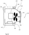
- the sealing system comprises a sealing means 206.
- the sealing means 206 may be located in the ventilation chamber 210, in the air inlet 203 or in the air outlet 214.
- the closing means 206 may be a hatch covering the entire section of the air extractor.
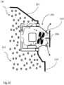
- the shutter means 206 is designed to be able to take or to be able to move between two positions: an open position ( Figure 2C ) allowing fluid communication between the air inlet and the air outlet of the air extractor and a closed position ( Figure 2B ) to prevent at least the passage of external particles between the air outlet and the air inlet.
- the closure means 206 is movable between two limit positions: the closed position and the open position.
- the sealing means 206 may cover a section of the air extractor so as to prevent at least external particles from passing through this section. Said section may be located in the ventilation chamber 210, in the inlet or the outlet of the air extractor.
- the sealing means 206 may be a hatch made of gas-impermeable material or of air-permeable material sealed against external particles.
- the sealing means 206 may be movable between a closed position ( Figure 2B ) and an open position ( Figure 2C ) by a translational movement or by a system of shutter(s).
- the air extractor 201 may also comprise seals 208 to ensure sealing between the extractor 201 and the projector 213 and/or between the walls of the extractor 201 and the sealing means 206.
- FIG. 2D figure illustrates a variant of the first embodiment, in which the closure means 206 is arranged at the entrance to the ventilation chamber 210.
- the two variant embodiments can also be combined.
- the projector further comprises a control device 209 for the air extractor 201, shown in the Figures 2A And 2D
- This control device may comprise an activator, arranged to control the opening and closing of the at least one closure means 206.
- the activator 209 may comprise a motor or an animated arm making it possible to move the closure means 206.
- the control device may, in addition, comprise a processor 207 and/or a printed circuit.
- the processor may be connected to the activator 209 by a communication means, in order to control the shutter means via the activator.
- the control device is configured to trigger the operation of the air extractor when the engine of the vehicle 101 is started, and to stop it when the engine is stopped.
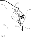
- FIGS. 3A And 3B represent an air extractor 301 according to a second embodiment, respectively in open and closed configuration.
- the air extractor 301 comprises at least one closure means 306 which can rotate.
- the closure means 306 can be rotatable about a pivot 309, oriented in the transverse direction.
- This closure means 306 is designed to, in the closed position represented by the Figure 3A , simultaneously close the inlet and outlet of the ventilation chamber 310. In the open position represented by the Figure 3B , it simultaneously opens the inlet and outlet of the ventilation chamber 310.
- this sealing means could open and close the air inlet 303 and the outlet 314 of the air extractor 301.
- the sealing means 306 is of sufficient length on either side of the pivot 309 to, in the closed position, allow the section of the inlet of the ventilation chamber 310 and the section of the outlet of the ventilation chamber 310 to be covered.
- the ventilation chamber 310 may comprise sealed joints 308 arranged between the pivot 309 and the wall of the projector 313.
- the extractor 301 may also include a seal 308 between the ventilation chamber and the projector walls.
- the sealing means 306 may comprise a surface 305 which is impervious to external particles and permeable to gases.
- the air extractor 301 further comprises an air guide 304 designed so that the air inlet of the extractor 303 is oriented upwards or towards the upper face of the projector 313.
- the extractor 301 can suck in the hotter gases 311, rather than the cooler gases 312 located in the lower part of the projector.
- an air extractor 401 likewise comprises an air inlet 403, then an air guide 404 towards a ventilation chamber 410 equipped with at least one fan 402.
- the sealing system comprises an outlet channel 405 having at least one curvature.
- This outlet channel 405 having at least one curvature is arranged between the ventilation chamber 410 comprising the fan 402 and the air outlet 414 of the air extractor 404.
- the outlet channel 405 may comprise several curvatures.
- said outlet channel 405 comprises a curvature of between 150° and 200°, that is to say that it guides the air extracted by the air extractor 401 along a trajectory comprising such a significant curvature, before its exit from the extractor.
- the outlet channel 405 further comprises a filter or grid 415 near the air outlet 414. This grid makes it possible to slow down or stop external particles, which will tend to settle on this grid rather than traveling the path through the outlet channel 405.
- the grid 415 covers the section of the outlet channel 405.
- the grid completely covers the section of the outlet channel 405 at the air outlet 414.
- the grid comprises a succession of flaps or wires. The spacing between each adjacent flap or between each adjacent wire is between 0.5 and 3 mm.
- the diameter or width of the section of the outlet channel 405 may be between 15 and 50 mm.
- the dimensions of the section of the outlet channel 405 contribute to the sealing of the air extractor 401, while allowing the passage of the air flow during operation of the fan 402.
- this solution is that it does away with the use of mechanical devices such as mobile sealing means, such as shutters.
- this solution can also do without an air filter.
- the outlet channel 405 may also be designed to, once mounted on the projector 413 and on a vehicle, have a slope so that any water present in the outlet channel, for example following a projection or by condensation, is evacuated by gravity through the air outlet 414 of the extractor 401.
- the air outlet 414 when the air extractor is mounted on a projector on a vehicle, is advantageously arranged at a lower height than the air outlet of the ventilation chamber 410.
- the ventilation chamber is designed to have a slope relative to a horizontal plane. This slope allows, once the extractor is mounted on a vehicle headlight, to allow water to flow outwards on the walls of the ventilation chamber, without penetrating into the headlight.
- the upper part of the ventilation chamber arranged outside the projector, has a slope with a horizontal plane so as to evacuate the water. In these embodiments, water cannot stagnate in the air extractor, nor penetrate inside the projector.
- a shutter may be movable in a movement other than a translation or a rotation, or in a translation in a direction other than that described in the first embodiment, or in a rotation around of an axis oriented in a direction other than that described in the second embodiment.
- the at least one closure means may comprise at least two or a plurality of flaps.
- the different flaps are configured to perform a rotational movement in a synchronized manner.
- Each flap is arranged to, in the closed position, cover a portion of the section of the air extractor.
- the flaps are arranged to, when they are all in the closed position, together completely cover the section of the air extractor.
- the at least one closure means comprises a double flap.
- the air extractor comprises a control device, such as that described with reference to the first embodiment.
- the step of activating the fan may be preceded by a step of receiving a control signal, for example a signal generated when the motor is switched on, is energized.
- a control signal for example a signal generated when the motor is switched on
- the deactivation step is performed at least one second, preferably at least 3 or 4 seconds, very preferably between 3 and 6 seconds after the execution of the movement step. In this way, it can be ensured that no dust can enter the interior of the projector through the extractor when it is switched off.
- the moving step may be preceded by a step of receiving a control signal, for example a signal generated when the motor is switched off, is powered down.
- a control signal for example a signal generated when the motor is switched off
Landscapes
- Engineering & Computer Science (AREA)
- General Engineering & Computer Science (AREA)
- Non-Portable Lighting Devices Or Systems Thereof (AREA)
- Arrangement Of Elements, Cooling, Sealing, Or The Like Of Lighting Devices (AREA)
- Lighting Device Outwards From Vehicle And Optical Signal (AREA)
- Projection Apparatus (AREA)
Claims (13)
- Anordnung, die einen an einem Fahrzeug angebrachten Scheinwerfer und einen in dem Scheinwerfer angeordneten Luftabsauger (201; 301; 401) aufweist, wobei der Luftabsauger (201; 301; 401) Folgendes aufweist:- einen Lufteinlass (203; 303; 403), der innerhalb des Scheinwerfers angeordnet ist, und einen Luftauslass (214; 314; 414), der außerhalb des Scheinwerfers angeordnet ist;- eine Belüftungskammer (210; 310; 410), die zwischen dem Lufteinlass (203; 303; 403) und dem Luftauslass (214; 314; 414) des Luftabsaugers angeordnet ist, wobei die Belüftungskammer (210; 310; 410) einen Ventilator (202; 302; 402) aufweist, der so angeordnet ist, dass er einen Luftstrom von dem Lufteinlass zu dem Luftauslass erzeugt; und- ein System zur Abdichtung gegen externe Partikel; wobei ein Teil der Belüftungskammer (210; 310; 410) außerhalb des Scheinwerfers angeordnet ist und einen oberen Teil mit einer Neigung zur horizontalen Ebene aufweist, wobei der Lufteinlass (203; 303; 403) eine Luftführung (204; 304; 404) aufweist, die an der Oberseite des Luftabsaugers ausgerichtet ist und den Lufteinlass (203; 303; 403) und die Belüftungskammer (210; 310; 410) fluidisch miteinander verbindet.
- Anordnung nach Anspruch 1, wobei das System zur Abdichtung gegen externe Partikel mindestens ein Verschlussmittel (206; 306) aufweist, das dazu ausgelegt ist, Folgendes anzunehmen:- eine offene Position, die eine Fluidverbindung zwischen dem Luftauslass und dem Lufteinlass zulässt; und- eine geschlossene Position, um zumindest den Durchgang von externe Partikeln zwischen dem Luftauslass und dem Lufteinlass zu verhindern.
- Anordnung nach Anspruch 2, die eine Vorrichtung zur Steuerung des mindestens einen Verschlussmittels (206; 306) aufweist.
- Anordnung nach Anspruch 2 oder Anspruch 3, wobei das mindestens eine Verschlussmittel (206; 306) im Luftauslass und/oder im Lufteinlass angeordnet ist.
- Anordnung nach einem der Ansprüche 2 bis 4, wobei das mindestens eine Verschlussmittel (206; 306) durch Drehung um eine Achse oder durch Translation zwischen der offenen Position und der geschlossenen Position beweglich ist.
- Anordnung nach Anspruch 1, wobei der das System zur Abdichtung gegen externe Partikel zwischen der Belüftungskammer und dem Luftauslass einen Kanal mit einer Krümmung aufweist.
- Anordnung nach dem vorhergehenden Anspruch, wobei der Kanal ein Gefälle für die Ableitung von Flüssigkeit in Richtung des Luftauslasses aufweist.
- Anordnung nach Anspruch 6 oder Anspruch 7, wobei der Luftauslass (414) ein Gitter (415) aufweist.
- Anordnung nach einem der Ansprüche 1 bis 8, dadurch gekennzeichnet, dass der Luftabsauger (201; 301; 401) an einem oberen und/oder hinteren Teil des Scheinwerfers angeordnet ist.
- Anordnung nach einem der Ansprüche 1 bis 9, dadurch gekennzeichnet, dass der Scheinwerfer einen Lufteinlass (104) aufweist, der an einem unteren und/oder vorderen Teil des Scheinwerfers angeordnet ist.
- Anordnung nach einem der Ansprüche 1 bis 10, dadurch gekennzeichnet, dass der Luftabsauger abnehmbar am Scheinwerfer befestigt ist.
- Anordnung nach einem der Ansprüche 1 bis 11, dadurch gekennzeichnet, dass der Scheinwerfer außerdem mindestens ein optisches Modul mit mindestens einer elektronischen Komponente und mindestens ein Kühlsystem für die elektronische Komponente aufweist, wobei das Kühlsystem nur ein konduktives Kühlsystem aufweist.
- Verfahren zur Steuerung einer Anordnung nach einem der Ansprüche 1 bis 12, wobei das System zur Abdichtung gegen externe Partikel ein bewegliches Verschlussmittel aufweist, dadurch gekennzeichnet, dass es die folgenden Schritte aufweist:- das Aktivieren des Ventilators und dann- das Öffnen des mindestens einen Verschlussmittels.
Applications Claiming Priority (1)
| Application Number | Priority Date | Filing Date | Title |
|---|---|---|---|
| FR1855040A FR3082279B1 (fr) | 2018-06-08 | 2018-06-08 | Extracteur d'air pour projecteur de vehicule automobile |
Publications (2)
| Publication Number | Publication Date |
|---|---|
| EP3587910A1 EP3587910A1 (de) | 2020-01-01 |
| EP3587910B1 true EP3587910B1 (de) | 2025-04-09 |
Family
ID=63145064
Family Applications (1)
| Application Number | Title | Priority Date | Filing Date |
|---|---|---|---|
| EP19178172.3A Active EP3587910B1 (de) | 2018-06-08 | 2019-06-04 | Sauglüfter für scheinwerfer eines kraftfahrzeugs |
Country Status (5)
| Country | Link |
|---|---|
| US (1) | US10767831B2 (de) |
| EP (1) | EP3587910B1 (de) |
| JP (1) | JP7401983B2 (de) |
| CN (1) | CN110578910A (de) |
| FR (1) | FR3082279B1 (de) |
Families Citing this family (3)
| Publication number | Priority date | Publication date | Assignee | Title |
|---|---|---|---|---|
| CZ310301B6 (cs) * | 2019-09-16 | 2025-02-05 | PO LIGHTING CZECH s.r.o. | Světelné zařízení pro motorové vozidlo |
| CN111921915A (zh) * | 2020-08-04 | 2020-11-13 | 海宁新月照明电器有限公司 | 一种用于采矿工人专用的照明头灯 |
| KR102344337B1 (ko) * | 2020-08-28 | 2021-12-29 | 우성파워텍주식회사 | 제습이 가능한 차량용 램프 |
Family Cites Families (23)
| Publication number | Priority date | Publication date | Assignee | Title |
|---|---|---|---|---|
| US4809144A (en) * | 1986-12-11 | 1989-02-28 | Stanley Electric Co., Ltd. | Vehicle headlamp with a vent hole |
| JP2526292Y2 (ja) * | 1989-08-31 | 1997-02-19 | 日産自動車株式会社 | 車両用ランプ |
| US5230719A (en) * | 1990-05-15 | 1993-07-27 | Erling Berner | Dehumidification apparatus |
| JPH0415108U (de) * | 1990-05-29 | 1992-02-06 | ||
| JP3245099B2 (ja) * | 1997-09-04 | 2002-01-07 | 株式会社小糸製作所 | 車両用灯具 |
| DE19814300B4 (de) | 1998-03-31 | 2008-09-25 | Bernhard Weber | Scheinwerfer oder Leuchte |
| FR2779804B1 (fr) * | 1998-06-11 | 2000-09-29 | Valeo Vision | Projecteur de vehicule automobile pourvu de moyens de refroidissement perfectionnes, et correcteur d'assiette associe |
| JP2002124123A (ja) * | 2000-10-17 | 2002-04-26 | Denso Corp | 車両用前照灯 |
| DE10359748A1 (de) * | 2003-12-19 | 2005-07-28 | Dr.Ing.H.C. F. Porsche Ag | Lichttechnische Einrichtung |
| US7217314B2 (en) * | 2005-01-10 | 2007-05-15 | Gore Enterprise Holdings, Inc. | Venting system for minimizing condensation in a lighting assembly |
| FR2913751A1 (fr) * | 2007-03-15 | 2008-09-19 | Valeo Vision Sa | Dispositif d'eclairage et/ou de signalisation pour vehicule automobile comprenant une paroi externe pourvue d'une zone d'eclairage thermique. |
| US20090268475A1 (en) * | 2008-04-24 | 2009-10-29 | Earl Ball | Ventilation system for lamp enclosures |
| FR2950674B1 (fr) * | 2009-09-30 | 2012-08-31 | Valeo Vision | Dispositif d'eclairage et/ou de signalisation pour vehicule automobile |
| DE102009055681A1 (de) * | 2009-11-25 | 2011-05-26 | Bayerische Motoren Werke Aktiengesellschaft | Kraftfahrzeugleuchte |
| JP6068886B2 (ja) * | 2012-03-30 | 2017-01-25 | 日東電工株式会社 | 換気システム |
| WO2013175538A1 (ja) * | 2012-05-24 | 2013-11-28 | 三菱電機株式会社 | 除湿装置、車載用灯具および光源点灯装置 |
| DE102013218327A1 (de) * | 2013-09-12 | 2015-03-12 | Automotive Lighting Reutlingen Gmbh | Kfz-Beleuchtungseinrichtung |
| JP6369307B2 (ja) | 2014-10-21 | 2018-08-08 | トヨタ自動車株式会社 | 車両用灯具の換気構造 |
| US9982857B2 (en) * | 2015-10-20 | 2018-05-29 | Toyota Motor Engineering & Manufacturing North America, Inc. | Vehicle lights including moisture management apparatuses |
| JP6416736B2 (ja) | 2015-11-12 | 2018-10-31 | トヨタ自動車株式会社 | 車両用前照灯 |
| KR101856359B1 (ko) * | 2016-09-13 | 2018-05-10 | 현대자동차주식회사 | 습기제거장치가 구비된 차량용 헤드램프 |
| DE102016122874A1 (de) * | 2016-11-28 | 2018-05-30 | Automotive Lighting Reutlingen Gmbh | Scheinwerfer und Verfahren zum Betreiben des Scheinwerfers |
| CN107917404A (zh) * | 2017-10-18 | 2018-04-17 | 浙江零跑科技有限公司 | 一种汽车前照灯降温、防雾系统及该车灯系统的车辆 |
-
2018
- 2018-06-08 FR FR1855040A patent/FR3082279B1/fr active Active
-
2019
- 2019-06-04 EP EP19178172.3A patent/EP3587910B1/de active Active
- 2019-06-07 US US16/434,378 patent/US10767831B2/en active Active
- 2019-06-07 JP JP2019106883A patent/JP7401983B2/ja active Active
- 2019-06-10 CN CN201910499197.0A patent/CN110578910A/zh active Pending
Also Published As
| Publication number | Publication date |
|---|---|
| US20190376660A1 (en) | 2019-12-12 |
| US10767831B2 (en) | 2020-09-08 |
| FR3082279A1 (fr) | 2019-12-13 |
| EP3587910A1 (de) | 2020-01-01 |
| JP2020017521A (ja) | 2020-01-30 |
| FR3082279B1 (fr) | 2021-06-11 |
| JP7401983B2 (ja) | 2023-12-20 |
| CN110578910A (zh) | 2019-12-17 |
Similar Documents
| Publication | Publication Date | Title |
|---|---|---|
| EP3463996B1 (de) | System zur reinigung eines optischen sensors, set mit system des besagten typs und zugehöriges kraftfahrzeug | |
| EP3587910A1 (de) | Sauglüfter für scheinwerfer eines kraftfahrzeugs | |
| EP3202628A1 (de) | Optisches erfassungssystem für kraftfahrzeug, und reinigungsvorrichtung eines solchen systems | |
| EP3252369B1 (de) | Beleuchtungs- und/oder signalisierungsvorrichtung für kraftfahrzeug, das ein leuchtmodul umfasst, das mithilfe eines luftstromerzeugenden generators gekühlt wird | |
| EP3629073A1 (de) | Schutzvorrichtung eines optischen sensors eines lenkassistenzsystems für kraftfahrzeug | |
| WO2017153660A1 (fr) | Systeme de refroidissement d'un vehicule automobile et un support pour module de face avant dudit vehicule adapte pour ledit systeme de refroidissement | |
| EP3543597B1 (de) | Beleuchtungsmodul, das mit einer mikro-spiegel-matrix mit optimierter kühlung ausgestattet ist | |
| WO2021123555A1 (fr) | Module de dispositif de ventilation pour module de refroidissement de véhicule automobile, dispositif de ventilation comportant un tel module et module de refroidissement pour véhicule automobile comprenant un tel dispositif de ventilation | |
| WO2021048494A1 (fr) | Procédé de fabrication d'un dispositif de ventilation pour module de refroidissement de véhicule automobile à turbomachine tangentielle | |
| EP0055665A1 (de) | Verfahren zur Vermeidung von Hitzeschäden an einem Rauchabzugsventilatormotor für Brandfälle und Einrichtung zur Ausführung dieses Verfahrens | |
| FR3077623A1 (fr) | Dispositif de regulation d’un flux d’air | |
| FR2981429A1 (fr) | Element de focalisation a couche transparente absorbant les rayons infrarouges | |
| EP3589512A1 (de) | Vorrichtung zur regelung einer luftströmung in einem ersten wärmetauscher für ein kraftfahrzeug | |
| EP3899404B1 (de) | Trägerrahmen für einen wärmetauscher | |
| FR2669992A1 (fr) | Dispositif de protection d'un systeme d'aeration d'appareil d'eclairage ou de signalisation, plus particulierement pour vehicules auttomobiles. | |
| FR3083180A1 (fr) | Procede de commande d'un extracteur d'air de projecteur pour un vehicule automobile. | |
| WO2017178727A1 (fr) | Dispositif de diffusion d'air a fuites reduites en configuration de fermeture | |
| FR2936191A1 (fr) | Dispositif anti-recyclage d'air pour un groupe moto-ventilateur d'un vehicule automobile. | |
| FR3064552A1 (fr) | Systeme de regulation d’un flux d’air amene a entrer dans un compartiment moteur d’un vehicule automobile | |
| FR3037125B1 (fr) | Dissipateur thermique pour module d'emission lumineuse, module d'emission lumineuse et dispositif lumineux associes | |
| WO2020136039A1 (fr) | Dispositif de protection d'un capteur optique | |
| EP0286540B1 (de) | Scheinwerfer für Kraftfahrzeuge mit einer mit Luftabzügen versehenen Kappe | |
| EP2571045B1 (de) | Flip-Chip-Hybridisierungsverfahren für die Bildung von hermetisch abgeschlossenen Hohlräumen, und durch dieses Verfahren erzielte Systeme | |
| EP4028654B1 (de) | Kühlmodul für ein motorfahrzeug, das eine tangentiale turbomachine umfasst | |
| EP1889527B1 (de) | Belüftungssystem |
Legal Events
| Date | Code | Title | Description |
|---|---|---|---|
| PUAI | Public reference made under article 153(3) epc to a published international application that has entered the european phase |
Free format text: ORIGINAL CODE: 0009012 |
|
| STAA | Information on the status of an ep patent application or granted ep patent |
Free format text: STATUS: THE APPLICATION HAS BEEN PUBLISHED |
|
| AK | Designated contracting states |
Kind code of ref document: A1 Designated state(s): AL AT BE BG CH CY CZ DE DK EE ES FI FR GB GR HR HU IE IS IT LI LT LU LV MC MK MT NL NO PL PT RO RS SE SI SK SM TR |
|
| AX | Request for extension of the european patent |
Extension state: BA ME |
|
| STAA | Information on the status of an ep patent application or granted ep patent |
Free format text: STATUS: REQUEST FOR EXAMINATION WAS MADE |
|
| 17P | Request for examination filed |
Effective date: 20200628 |
|
| RBV | Designated contracting states (corrected) |
Designated state(s): AL AT BE BG CH CY CZ DE DK EE ES FI FR GB GR HR HU IE IS IT LI LT LU LV MC MK MT NL NO PL PT RO RS SE SI SK SM TR |
|
| STAA | Information on the status of an ep patent application or granted ep patent |
Free format text: STATUS: EXAMINATION IS IN PROGRESS |
|
| 17Q | First examination report despatched |
Effective date: 20220621 |
|
| P01 | Opt-out of the competence of the unified patent court (upc) registered |
Effective date: 20230528 |
|
| GRAP | Despatch of communication of intention to grant a patent |
Free format text: ORIGINAL CODE: EPIDOSNIGR1 |
|
| STAA | Information on the status of an ep patent application or granted ep patent |
Free format text: STATUS: GRANT OF PATENT IS INTENDED |
|
| INTG | Intention to grant announced |
Effective date: 20241111 |
|
| GRAS | Grant fee paid |
Free format text: ORIGINAL CODE: EPIDOSNIGR3 |
|
| GRAA | (expected) grant |
Free format text: ORIGINAL CODE: 0009210 |
|
| STAA | Information on the status of an ep patent application or granted ep patent |
Free format text: STATUS: THE PATENT HAS BEEN GRANTED |
|
| AK | Designated contracting states |
Kind code of ref document: B1 Designated state(s): AL AT BE BG CH CY CZ DE DK EE ES FI FR GB GR HR HU IE IS IT LI LT LU LV MC MK MT NL NO PL PT RO RS SE SI SK SM TR |
|
| REG | Reference to a national code |
Ref country code: GB Ref legal event code: FG4D Free format text: NOT ENGLISH |
|
| REG | Reference to a national code |
Ref country code: CH Ref legal event code: EP |
|
| REG | Reference to a national code |
Ref country code: DE Ref legal event code: R096 Ref document number: 602019068332 Country of ref document: DE |
|
| REG | Reference to a national code |
Ref country code: IE Ref legal event code: FG4D Free format text: LANGUAGE OF EP DOCUMENT: FRENCH |
|
| PGFP | Annual fee paid to national office [announced via postgrant information from national office to epo] |
Ref country code: DE Payment date: 20250617 Year of fee payment: 7 |
|
| PGFP | Annual fee paid to national office [announced via postgrant information from national office to epo] |
Ref country code: FR Payment date: 20250630 Year of fee payment: 7 |
|
| REG | Reference to a national code |
Ref country code: NL Ref legal event code: MP Effective date: 20250409 |
|
| PG25 | Lapsed in a contracting state [announced via postgrant information from national office to epo] |
Ref country code: NL Free format text: LAPSE BECAUSE OF FAILURE TO SUBMIT A TRANSLATION OF THE DESCRIPTION OR TO PAY THE FEE WITHIN THE PRESCRIBED TIME-LIMIT Effective date: 20250409 |
|
| REG | Reference to a national code |
Ref country code: AT Ref legal event code: MK05 Ref document number: 1783797 Country of ref document: AT Kind code of ref document: T Effective date: 20250409 |
|
| PG25 | Lapsed in a contracting state [announced via postgrant information from national office to epo] |
Ref country code: FI Free format text: LAPSE BECAUSE OF FAILURE TO SUBMIT A TRANSLATION OF THE DESCRIPTION OR TO PAY THE FEE WITHIN THE PRESCRIBED TIME-LIMIT Effective date: 20250409 Ref country code: ES Free format text: LAPSE BECAUSE OF FAILURE TO SUBMIT A TRANSLATION OF THE DESCRIPTION OR TO PAY THE FEE WITHIN THE PRESCRIBED TIME-LIMIT Effective date: 20250409 Ref country code: PT Free format text: LAPSE BECAUSE OF FAILURE TO SUBMIT A TRANSLATION OF THE DESCRIPTION OR TO PAY THE FEE WITHIN THE PRESCRIBED TIME-LIMIT Effective date: 20250811 |
|
| REG | Reference to a national code |
Ref country code: LT Ref legal event code: MG9D |
|
| PG25 | Lapsed in a contracting state [announced via postgrant information from national office to epo] |
Ref country code: NO Free format text: LAPSE BECAUSE OF FAILURE TO SUBMIT A TRANSLATION OF THE DESCRIPTION OR TO PAY THE FEE WITHIN THE PRESCRIBED TIME-LIMIT Effective date: 20250709 Ref country code: GR Free format text: LAPSE BECAUSE OF FAILURE TO SUBMIT A TRANSLATION OF THE DESCRIPTION OR TO PAY THE FEE WITHIN THE PRESCRIBED TIME-LIMIT Effective date: 20250710 |
|
| PG25 | Lapsed in a contracting state [announced via postgrant information from national office to epo] |
Ref country code: PL Free format text: LAPSE BECAUSE OF FAILURE TO SUBMIT A TRANSLATION OF THE DESCRIPTION OR TO PAY THE FEE WITHIN THE PRESCRIBED TIME-LIMIT Effective date: 20250409 |
|
| PG25 | Lapsed in a contracting state [announced via postgrant information from national office to epo] |
Ref country code: BG Free format text: LAPSE BECAUSE OF FAILURE TO SUBMIT A TRANSLATION OF THE DESCRIPTION OR TO PAY THE FEE WITHIN THE PRESCRIBED TIME-LIMIT Effective date: 20250409 |
|
| PG25 | Lapsed in a contracting state [announced via postgrant information from national office to epo] |
Ref country code: HR Free format text: LAPSE BECAUSE OF FAILURE TO SUBMIT A TRANSLATION OF THE DESCRIPTION OR TO PAY THE FEE WITHIN THE PRESCRIBED TIME-LIMIT Effective date: 20250409 |
|
| PG25 | Lapsed in a contracting state [announced via postgrant information from national office to epo] |
Ref country code: AT Free format text: LAPSE BECAUSE OF FAILURE TO SUBMIT A TRANSLATION OF THE DESCRIPTION OR TO PAY THE FEE WITHIN THE PRESCRIBED TIME-LIMIT Effective date: 20250409 |
|
| PG25 | Lapsed in a contracting state [announced via postgrant information from national office to epo] |
Ref country code: RS Free format text: LAPSE BECAUSE OF FAILURE TO SUBMIT A TRANSLATION OF THE DESCRIPTION OR TO PAY THE FEE WITHIN THE PRESCRIBED TIME-LIMIT Effective date: 20250709 |
|
| PG25 | Lapsed in a contracting state [announced via postgrant information from national office to epo] |
Ref country code: IS Free format text: LAPSE BECAUSE OF FAILURE TO SUBMIT A TRANSLATION OF THE DESCRIPTION OR TO PAY THE FEE WITHIN THE PRESCRIBED TIME-LIMIT Effective date: 20250809 |
|
| PG25 | Lapsed in a contracting state [announced via postgrant information from national office to epo] |
Ref country code: LV Free format text: LAPSE BECAUSE OF FAILURE TO SUBMIT A TRANSLATION OF THE DESCRIPTION OR TO PAY THE FEE WITHIN THE PRESCRIBED TIME-LIMIT Effective date: 20250409 |
|
| REG | Reference to a national code |
Ref country code: DE Ref legal event code: R097 Ref document number: 602019068332 Country of ref document: DE |
|
| PG25 | Lapsed in a contracting state [announced via postgrant information from national office to epo] |
Ref country code: DK Free format text: LAPSE BECAUSE OF FAILURE TO SUBMIT A TRANSLATION OF THE DESCRIPTION OR TO PAY THE FEE WITHIN THE PRESCRIBED TIME-LIMIT Effective date: 20250409 Ref country code: SM Free format text: LAPSE BECAUSE OF FAILURE TO SUBMIT A TRANSLATION OF THE DESCRIPTION OR TO PAY THE FEE WITHIN THE PRESCRIBED TIME-LIMIT Effective date: 20250409 |
|
| PG25 | Lapsed in a contracting state [announced via postgrant information from national office to epo] |
Ref country code: CZ Free format text: LAPSE BECAUSE OF FAILURE TO SUBMIT A TRANSLATION OF THE DESCRIPTION OR TO PAY THE FEE WITHIN THE PRESCRIBED TIME-LIMIT Effective date: 20250409 |
|
| PG25 | Lapsed in a contracting state [announced via postgrant information from national office to epo] |
Ref country code: EE Free format text: LAPSE BECAUSE OF FAILURE TO SUBMIT A TRANSLATION OF THE DESCRIPTION OR TO PAY THE FEE WITHIN THE PRESCRIBED TIME-LIMIT Effective date: 20250409 |
|
| PG25 | Lapsed in a contracting state [announced via postgrant information from national office to epo] |
Ref country code: RO Free format text: LAPSE BECAUSE OF FAILURE TO SUBMIT A TRANSLATION OF THE DESCRIPTION OR TO PAY THE FEE WITHIN THE PRESCRIBED TIME-LIMIT Effective date: 20250409 Ref country code: SK Free format text: LAPSE BECAUSE OF FAILURE TO SUBMIT A TRANSLATION OF THE DESCRIPTION OR TO PAY THE FEE WITHIN THE PRESCRIBED TIME-LIMIT Effective date: 20250409 |
|
| REG | Reference to a national code |
Ref country code: CH Ref legal event code: H13 Free format text: ST27 STATUS EVENT CODE: U-0-0-H10-H13 (AS PROVIDED BY THE NATIONAL OFFICE) Effective date: 20260127 |
|
| PG25 | Lapsed in a contracting state [announced via postgrant information from national office to epo] |
Ref country code: IT Free format text: LAPSE BECAUSE OF FAILURE TO SUBMIT A TRANSLATION OF THE DESCRIPTION OR TO PAY THE FEE WITHIN THE PRESCRIBED TIME-LIMIT Effective date: 20250409 |
|
| PG25 | Lapsed in a contracting state [announced via postgrant information from national office to epo] |
Ref country code: MC Free format text: LAPSE BECAUSE OF FAILURE TO SUBMIT A TRANSLATION OF THE DESCRIPTION OR TO PAY THE FEE WITHIN THE PRESCRIBED TIME-LIMIT Effective date: 20250409 |
|
| PLBE | No opposition filed within time limit |
Free format text: ORIGINAL CODE: 0009261 |
|
| STAA | Information on the status of an ep patent application or granted ep patent |
Free format text: STATUS: NO OPPOSITION FILED WITHIN TIME LIMIT |
|
| PG25 | Lapsed in a contracting state [announced via postgrant information from national office to epo] |
Ref country code: LU Free format text: LAPSE BECAUSE OF NON-PAYMENT OF DUE FEES Effective date: 20250604 |
|
| REG | Reference to a national code |
Ref country code: CH Ref legal event code: L10 Free format text: ST27 STATUS EVENT CODE: U-0-0-L10-L00 (AS PROVIDED BY THE NATIONAL OFFICE) Effective date: 20260218 |
|
| REG | Reference to a national code |
Ref country code: BE Ref legal event code: MM Effective date: 20250630 |
|
| 26N | No opposition filed |
Effective date: 20260112 |
|
| GBPC | Gb: european patent ceased through non-payment of renewal fee |
Effective date: 20250709 |
|
| PG25 | Lapsed in a contracting state [announced via postgrant information from national office to epo] |
Ref country code: GB Free format text: LAPSE BECAUSE OF NON-PAYMENT OF DUE FEES Effective date: 20250709 |
|
| PG25 | Lapsed in a contracting state [announced via postgrant information from national office to epo] |
Ref country code: IE Free format text: LAPSE BECAUSE OF NON-PAYMENT OF DUE FEES Effective date: 20250604 |
|
| PG25 | Lapsed in a contracting state [announced via postgrant information from national office to epo] |
Ref country code: BE Free format text: LAPSE BECAUSE OF NON-PAYMENT OF DUE FEES Effective date: 20250630 |
|
| PG25 | Lapsed in a contracting state [announced via postgrant information from national office to epo] |
Ref country code: CH Free format text: LAPSE BECAUSE OF NON-PAYMENT OF DUE FEES Effective date: 20250630 |