EP4028654B1 - Kühlmodul für ein motorfahrzeug, das eine tangentiale turbomachine umfasst - Google Patents
Kühlmodul für ein motorfahrzeug, das eine tangentiale turbomachine umfasst Download PDFInfo
- Publication number
- EP4028654B1 EP4028654B1 EP20780769.4A EP20780769A EP4028654B1 EP 4028654 B1 EP4028654 B1 EP 4028654B1 EP 20780769 A EP20780769 A EP 20780769A EP 4028654 B1 EP4028654 B1 EP 4028654B1
- Authority
- EP
- European Patent Office
- Prior art keywords
- shutters
- ventilation device
- shutter
- frame
- cooling module
- Prior art date
- Legal status (The legal status is an assumption and is not a legal conclusion. Google has not performed a legal analysis and makes no representation as to the accuracy of the status listed.)
- Active
Links
Images


Classifications
-
- B—PERFORMING OPERATIONS; TRANSPORTING
- B60—VEHICLES IN GENERAL
- B60K—ARRANGEMENT OR MOUNTING OF PROPULSION UNITS OR OF TRANSMISSIONS IN VEHICLES; ARRANGEMENT OR MOUNTING OF PLURAL DIVERSE PRIME-MOVERS IN VEHICLES; AUXILIARY DRIVES FOR VEHICLES; INSTRUMENTATION OR DASHBOARDS FOR VEHICLES; ARRANGEMENTS IN CONNECTION WITH COOLING, AIR INTAKE, GAS EXHAUST OR FUEL SUPPLY OF PROPULSION UNITS IN VEHICLES
- B60K11/00—Arrangement in connection with cooling of propulsion units
- B60K11/08—Air inlets for cooling; Shutters or blinds therefor
- B60K11/085—Air inlets for cooling; Shutters or blinds therefor with adjustable shutters or blinds
-
- B—PERFORMING OPERATIONS; TRANSPORTING
- B60—VEHICLES IN GENERAL
- B60K—ARRANGEMENT OR MOUNTING OF PROPULSION UNITS OR OF TRANSMISSIONS IN VEHICLES; ARRANGEMENT OR MOUNTING OF PLURAL DIVERSE PRIME-MOVERS IN VEHICLES; AUXILIARY DRIVES FOR VEHICLES; INSTRUMENTATION OR DASHBOARDS FOR VEHICLES; ARRANGEMENTS IN CONNECTION WITH COOLING, AIR INTAKE, GAS EXHAUST OR FUEL SUPPLY OF PROPULSION UNITS IN VEHICLES
- B60K11/00—Arrangement in connection with cooling of propulsion units
- B60K11/06—Arrangement in connection with cooling of propulsion units with air cooling
-
- F—MECHANICAL ENGINEERING; LIGHTING; HEATING; WEAPONS; BLASTING
- F01—MACHINES OR ENGINES IN GENERAL; ENGINE PLANTS IN GENERAL; STEAM ENGINES
- F01P—COOLING OF MACHINES OR ENGINES IN GENERAL; COOLING OF INTERNAL-COMBUSTION ENGINES
- F01P11/00—Component parts, details, or accessories not provided for in, or of interest apart from, groups F01P1/00 - F01P9/00
- F01P11/10—Guiding or ducting cooling-air, to, or from, liquid-to-air heat exchangers
-
- F—MECHANICAL ENGINEERING; LIGHTING; HEATING; WEAPONS; BLASTING
- F01—MACHINES OR ENGINES IN GENERAL; ENGINE PLANTS IN GENERAL; STEAM ENGINES
- F01P—COOLING OF MACHINES OR ENGINES IN GENERAL; COOLING OF INTERNAL-COMBUSTION ENGINES
- F01P5/00—Pumping cooling-air or liquid coolants
- F01P5/02—Pumping cooling-air; Arrangements of cooling-air pumps, e.g. fans or blowers
- F01P5/06—Guiding or ducting air to, or from, ducted fans
-
- F—MECHANICAL ENGINEERING; LIGHTING; HEATING; WEAPONS; BLASTING
- F01—MACHINES OR ENGINES IN GENERAL; ENGINE PLANTS IN GENERAL; STEAM ENGINES
- F01P—COOLING OF MACHINES OR ENGINES IN GENERAL; COOLING OF INTERNAL-COMBUSTION ENGINES
- F01P7/00—Controlling of coolant flow
- F01P7/02—Controlling of coolant flow the coolant being cooling-air
- F01P7/10—Controlling of coolant flow the coolant being cooling-air by throttling amount of air flowing through liquid-to-air heat exchangers
-
- F—MECHANICAL ENGINEERING; LIGHTING; HEATING; WEAPONS; BLASTING
- F04—POSITIVE - DISPLACEMENT MACHINES FOR LIQUIDS; PUMPS FOR LIQUIDS OR ELASTIC FLUIDS
- F04D—NON-POSITIVE-DISPLACEMENT PUMPS
- F04D17/00—Radial-flow pumps, e.g. centrifugal pumps; Helico-centrifugal pumps
- F04D17/02—Radial-flow pumps, e.g. centrifugal pumps; Helico-centrifugal pumps having non-centrifugal stages, e.g. centripetal
- F04D17/04—Radial-flow pumps, e.g. centrifugal pumps; Helico-centrifugal pumps having non-centrifugal stages, e.g. centripetal of transverse-flow type
-
- F—MECHANICAL ENGINEERING; LIGHTING; HEATING; WEAPONS; BLASTING
- F04—POSITIVE - DISPLACEMENT MACHINES FOR LIQUIDS; PUMPS FOR LIQUIDS OR ELASTIC FLUIDS
- F04D—NON-POSITIVE-DISPLACEMENT PUMPS
- F04D25/00—Pumping installations or systems
- F04D25/02—Units comprising pumps and their driving means
- F04D25/08—Units comprising pumps and their driving means the working fluid being air, e.g. for ventilation
- F04D25/12—Units comprising pumps and their driving means the working fluid being air, e.g. for ventilation the unit being adapted for mounting in apertures
- F04D25/14—Units comprising pumps and their driving means the working fluid being air, e.g. for ventilation the unit being adapted for mounting in apertures and having shutters, e.g. automatically closed when not in use
-
- F—MECHANICAL ENGINEERING; LIGHTING; HEATING; WEAPONS; BLASTING
- F04—POSITIVE - DISPLACEMENT MACHINES FOR LIQUIDS; PUMPS FOR LIQUIDS OR ELASTIC FLUIDS
- F04D—NON-POSITIVE-DISPLACEMENT PUMPS
- F04D29/00—Details, component parts, or accessories
- F04D29/40—Casings; Connections of working fluid
- F04D29/42—Casings; Connections of working fluid for radial or helico-centrifugal pumps
- F04D29/4206—Casings; Connections of working fluid for radial or helico-centrifugal pumps especially adapted for elastic fluid pumps
- F04D29/4226—Fan casings
-
- F—MECHANICAL ENGINEERING; LIGHTING; HEATING; WEAPONS; BLASTING
- F04—POSITIVE - DISPLACEMENT MACHINES FOR LIQUIDS; PUMPS FOR LIQUIDS OR ELASTIC FLUIDS
- F04D—NON-POSITIVE-DISPLACEMENT PUMPS
- F04D29/00—Details, component parts, or accessories
- F04D29/40—Casings; Connections of working fluid
- F04D29/42—Casings; Connections of working fluid for radial or helico-centrifugal pumps
- F04D29/44—Fluid-guiding means, e.g. diffusers
- F04D29/46—Fluid-guiding means, e.g. diffusers adjustable
- F04D29/462—Fluid-guiding means, e.g. diffusers adjustable especially adapted for elastic fluid pumps
-
- Y—GENERAL TAGGING OF NEW TECHNOLOGICAL DEVELOPMENTS; GENERAL TAGGING OF CROSS-SECTIONAL TECHNOLOGIES SPANNING OVER SEVERAL SECTIONS OF THE IPC; TECHNICAL SUBJECTS COVERED BY FORMER USPC CROSS-REFERENCE ART COLLECTIONS [XRACs] AND DIGESTS
- Y02—TECHNOLOGIES OR APPLICATIONS FOR MITIGATION OR ADAPTATION AGAINST CLIMATE CHANGE
- Y02T—CLIMATE CHANGE MITIGATION TECHNOLOGIES RELATED TO TRANSPORTATION
- Y02T10/00—Road transport of goods or passengers
- Y02T10/80—Technologies aiming to reduce greenhouse gasses emissions common to all road transportation technologies
- Y02T10/88—Optimized components or subsystems, e.g. lighting, actively controlled glasses
Definitions
- the invention relates to a cooling module for a motor vehicle, with a tangential turbomachine.
- the invention also relates to a motor vehicle equipped with such a cooling module.
- a motor vehicle heat exchanger generally comprises tubes, in which a heat transfer fluid is intended to circulate, in particular a liquid such as water, and heat exchange elements connected to these tubes, often referred to as "fins" or “spacers".
- the fins increase the exchange surface area between the tubes and the ambient air.
- a ventilation device in order to further increase the heat exchange between the heat transfer fluid and the ambient air, it is common for a ventilation device to be used in addition, to generate or increase an air flow directed towards the tubes and fins.
- such a ventilation device comprises a propeller fan.
- the airflow generated by the blades of such a fan is turbulent, in particular due to the circular geometry of the propeller, and generally only reaches part of the surface of the heat exchanger (circular area of the exchanger facing the fan propeller).
- the heat exchange therefore does not take place homogeneously over the entire surface of the tubes and fins.
- the blades when the fan is not required to be switched on (typically when the heat exchange with non-accelerated ambient air is sufficient to cool the heat transfer fluid circulating in the exchanger), the blades partially obstruct the flow of ambient air towards the tubes and fins, which obstructs the circulation of air towards the exchanger and thus limits the exchange of heat with the heat transfer fluid.
- Ventilation device for motor vehicle cooling module comprising a tangential turbomachine are shown in the documents DE102008020310A1 And DE102017203858A1 .
- the aim of the invention is to at least partially remedy these drawbacks.
- At least one tangential turbomachine is used which makes it possible to obtain a better distributed air flow over one or more exchangers of generally rectangular shape.
- the presence of shutters allowing to selectively close a opening in the frame, allows to increase the air flow through the heat exchanger(s), when the turbomachine(s) are off and the air flow is produced by the speed of the moving vehicle.
- the actuator described above is simple to make and particularly robust. It allows synchronized control of the rotation of the flaps.
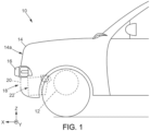
- a motor vehicle comprising a body and a cooling module as described above, the bodywork defining at least one cooling bay, the cooling module being arranged opposite the at least one cooling bay.
- the cooling module 22 is more clearly visible on the figures 2 to 4 .
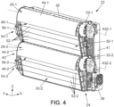
- the cooling module 22 comprises a ventilation device 24 associated with at least one heat exchanger 26.
- the ventilation device 24 comprises at least one tangential fan, or more generally a tangential turbomachine, which draws in a flow of air in contact with heat or heat exchangers 26.
- the cooling module 24 comprises two tangential turbomachines 28-1, 28-2, detailed below.
- the cooling module 22 essentially comprises a housing or frame 30 forming an internal air channel.
- the frame 30 makes it possible to house at least one tangential turbomachine.
- a rear part of the frame 30 forms in particular here the volute 30-1, 30-2 of a tangential turbomachine 28-1, 28-2.
- the heat exchanger(s) 26 is/are arranged in the internal air channel.
- Each tangential turbomachine 28-1, 28-2 comprises a rotor 32-1, 32-2.
- the rotor here consists of a turbine 32-1, 32-2, more precisely a tangential propeller or bladed wheel.
- Each turbine 32-1, 32-2 has a cylindrical shape.
- Each turbine 32-1, 32-2 advantageously comprises several stages of blades (or blades).
- Each turbine 32-1, 32-2 is rotatably mounted around an associated rotation axis A32-1, A32-2.
- Each turbine 32-1, 32-2 is rotated by an associated motor 33-1, 33-2.
- all of the heat exchangers 26 delimit a surface S, called the working surface, a section of which is substantially rectangular in a plane (Y, Z).
- the Y direction corresponds to a horizontal direction, more preferably transverse, while the Z direction corresponds to a vertical direction, when the module is installed in the motor vehicle.
- the surface S is delimited by two opposite end edges 38, 39 extending in the direction Y, called length, and by two other opposite end edges 40, 41, in the direction Z, called height.
- the surface S corresponds to the rectangle defined by the exchanger 26, or if several exchangers are present, by the largest heat exchanger. However, it is also possible to juxtapose several exchangers vertically and/or horizontally, in which case the height of the surface S is the sum of the heights of the vertically juxtaposed (superimposed) exchangers, and the length of the surface S is the sum of the lengths of the horizontally juxtaposed exchangers.
- the first and second turbomachines 28-1 and 28-2 are mounted parallel to each other, that is to say that the air flow F1 ejected from the first turbine 32-1 of the first turbomachine 28-1 is distinct from the air flow F2 ejected from the second turbine 32-2 of the second turbomachine 28-2. In other words, the air flow F1 ejected from the first turbine 32-1 does not pass through the second turbine 32-2 and vice versa.
- the axes of rotation A32-1, A32-2 are parallel to the Y direction.
- the two turbines 32-1, 32-2 are thus mounted horizontally, in this case in a transverse direction.
- the axes of rotation A32-1, A32-2 can be vertical, i.e. parallel to the Z axis.
- the volute 30-1 of the first turbomachine 28-1 comprises a first air guide portion 44-1 around the first turbomachine 32-1 to a first outlet 46-1 of the air from the module 22.
- the first air guide portion 44-1 advantageously comprises a wall in the form of a truncated spiral.
- volute 30-2 of the second turbomachine 28-2 comprises a second air guide portion 44-2 around the second turbomachine 32-2 to an air outlet from the module 22, referenced 46-2.
- the second guide portion 44-2 advantageously comprises a wall in the form of a truncated spiral.
- the two outlets 46-1, 46-2 are arranged opposite each other, oriented substantially in the same direction. This makes it possible to reduce the acoustic waves generated by the cooling module 22, compared to a configuration where the two outlets face each other and are oriented in opposite directions.
- the illustrated configuration ensures that the air distribution of a first air flow F1 from the first turbomachine 28-1 via the associated first outlet 46-1 is substantially the same direction and in particular in the same direction as the distribution of a second air flow F2 from the second turbomachine 28-2 via the associated second outlet 46-2.
- the first and second air flows F1 and F2 are substantially vertical, and oriented downwards.
- a grid (not shown in the figures) is fixed to each of the outlets 46-1, 46-2.
- Such a grid can in particular prevent projections from entering the housing receiving the turbine 32-1, 32-2 and damaging this turbine 32-1, 32-2.
- the axis of rotation A32-1 of the first turbomachine 28-1 is arranged substantially opposite the longitudinal edge 38 upper surface S and the rotation axis A32-2 of the second turbomachine 28-2 is arranged in the middle of the height of the surface S.
- turbomachines 28-1, 28-2 are positions so as to dedicate them to respective exchangers 26.
- Other relative positions of turbomachines 28-1, 28-2 are also possible.
- the axis of rotation A32-2 of the second turbomachine 28-2 is arranged in an area between one fifth and four fifths of the height, preferably between one third and two thirds of said height, of the working surface S.
- the module 22 is provided with air guide means 50-1, 50-2 associated with each turbomachine 28-1, 28-2 (these means are removed on the Figure 2 for the purpose of visibility of interchange 26).
- Each air guide means 50-1, 50-2 comprises a plurality of flaps 52-1, 52-2.
- Each plurality of flaps 52-1, 52-2 is pivotally mounted between a closed position, illustrated in Figure 4 , in which the flaps 52-1, 52-2 close a respective opening 51-1, 51-2 formed by the frame 30 of the cooling module 22, and at least one open position, in which the flaps 52-1, 52-2 allow at least part of the air flow to pass through the associated opening 51-1, 51-2. In the closed position of the flaps 52-1, 52-2, these allow the created air flow to be directed towards the associated turbomachine 28-1, 28-2.
- the airflow is thus “diverted” from the turbomachine 28-1, 28-2.
- the open position is particularly advantageous when the vehicle is traveling at high speed, in which case it is possible to shut down the turbomachines 28-1, 28-2.
- the number of flaps 52-1 associated with the first turbomachine 28-1 may be identical or on the contrary different from the number of flaps 52-2 associated with the second turbomachine 28-2, depending on the respective position of the turbomachines 28-1, 28-2, in particular.
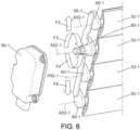
- Each plurality of flaps 52-1, 52-2 is associated with a respective actuator 54-1, 54-2.
- An actuator 54-1 is described in more detail below, with reference to the figures 5 And 6 , it being understood that the actuator 54-2 may be identical.
- the actuator 54-1 firstly comprises an electric motor 56-1 whose output shaft drives a first flap 52-1 in rotation.
- the actuator 54-1 also comprises a connecting rod 58-1, the connecting rod 58-1 connecting together the first flap 52-1, driven in rotation by the output shaft of the electric motor 56-1, to the other flaps 52-1 of the plurality of flaps 52-1, such that the rotation of the first flap 52-1 is transmitted to the other flaps 52-1 of the plurality of flaps 52-1.
- each flap 52-1 comprises, at a first end, a cam 60-1.
- the axis of each cam 60-1 corresponds to the axis A52-1 of rotation of the associated flap 52-1.
- the cams 60-1 associated with the different flaps 52-1 are connected together by the connecting rod 58-1.
- the connecting rod 58-1 comprises a lug associated with each cam 60-1, received in a complementary housing formed in the cam 60-1, such that the lug received in the housing can pivot relative to the cam 60-1.
- the cam 60-1 associated with the first flap 52-1 is driven in rotation by the output shaft of the electric motor 56-1, either directly or via a reduction gear.
- the attachment point of the connecting rod 58-1 on each cam 60-1 is offset relative to the axis A52-1 of rotation of the associated flap 52-1.
- each flap 52-1 has a stud 62-1 received in a complementary housing 64-1 formed on a first upright 66-1 of the actuator 54-1.
- the first upright 66-1 may be formed in whole or in part by the housing 30 of the cooling module 22.
- the stud 62-1 and the complementary housing 64-1 are for example cylindrical, of circular section.
- the cams 60-1 are also received in complementary housings, to guide their rotation around the axis A52-1 of rotation of the associated flap 52-1.
- the housings are formed in a second upright 68-1.
- the second upright 68-1 may be formed in whole or in part by the housing 30 of the cooling module 22.
- the rotation F3, F4 of the first flap 52-1 is caused around its axis of rotation A52-1.
- the rotation F3, F4 of this first flap 52-1 causes the rotation of the associated cam 60-1, which in turn causes the displacement F5, F6, here vertical, of the connecting rod 58-1.
- the displacement F5, F6 of the connecting rod 58-1 causes the rotation of the other cams 60-1 and, consequently, of the other flaps 52-1 of the plurality of flaps 52-1.
- each flap 52-1 has a rib 70-1 along a first longitudinal side and a groove 72-1 of a shape complementary to the rib 70-1, along a second longitudinal side, such that the rib 70-1 of a first flap 52-1 is received in the groove 72-1 of a second neighboring flap 52-1 in the closed position of the flaps 52-1.
- each flap 52-1 may be tubular.
- the face of a flap 52-1 intended to be oriented towards the heat exchanger(s) 26 is substantially flat.
- the flat faces of the flaps 52-1 are aligned in the closed position of the flaps 52-1, to form a substantially flat surface for guiding the air flow. This makes it possible to limit the pressure losses of the air flow.
- the opposite face of the flaps 52-1 is preferably curved.
- each flap 52-1, 52-2 can be pivoted over an angular range of amplitude between 90° and 110°, preferably of amplitude 102.5°.
- One of the two extreme positions of the flaps 52-1 corresponds here to the closed position of the flaps 52-1, in which the aligned flat faces of the flaps 52-1 form an angle ⁇ between 5° and 20°, preferably substantially equal to 12.5° with an air inlet surface S2, normal to the air flow entering the ventilation device 24.
- the other of the two extreme positions of the flaps 52-1 corresponds to a position of the flaps 52-1 in which the flat surfaces of the flaps 52-1 extend substantially horizontally, that is to say substantially parallel to the air flow entering the ventilation device 24. In this position, the resistance of the flaps 52-1, 52-2 to the air flow passing through the associated opening 51-1, 51-2 is minimized.
Landscapes
- Engineering & Computer Science (AREA)
- Mechanical Engineering (AREA)
- General Engineering & Computer Science (AREA)
- Chemical & Material Sciences (AREA)
- Combustion & Propulsion (AREA)
- Transportation (AREA)
- Cooling, Air Intake And Gas Exhaust, And Fuel Tank Arrangements In Propulsion Units (AREA)
Claims (9)
- Belüftungsvorrichtung (24) für ein Kühlmodul (22) eines Kraftfahrzeugs (10), welche umfasst:- mindestens eine tangentiale Turbomaschine (28-1; 28-2), die ein Schaufelrad (32-1; 32-2) und einen Motor (33-1; 33-2), um das Schaufelrad (32-1; 32-2) drehend anzutreiben, umfasst,- mindestens einen Rahmen (30), der einen Aufnahmeraum (30-1; 30-2) bildet, der geeignet ist, das Schaufelrad (32-1; 32-2) aufzunehmen,- mehrere Klappen (52-1; 52-2), die bezüglich des Rahmens (30) schwenkbar gelagert sind, wobei die mehreren Klappen (52-1; 52-2) dazu eingerichtet sind, eine Öffnung (51-1; 51-2) im Rahmen (30) selektiv zu verschließen, und- einen Stellantrieb (54-1; 54-2) zum Steuern der Schwenkung der mehreren Klappen (52-1; 52-2), dadurch gekennzeichnet, dass:und dadurch, dass in der Position des Verschließens der Öffnung (51-1; 51-2) durch die Klappen (52-1; 52-2) die Klappen (52-1; 52-2) eine im Wesentlichen ebene Fläche bilden, die mit einer zu dem Luftstrom am Einlass der Belüftungsvorrichtung (22) senkrechten Lufteintrittsfläche (S2) einen Winkel (α) zwischen 5 und 20° bildet, der vorzugsweise im Wesentlichen gleich 12,5° ist.der Stellantrieb (54-1; 54-2) umfasst:- einen Elektromotor (56-1; 56-2), dessen Abtriebswelle eine von den mehreren Klappen (52-1; 52-2) drehend antreibt;- mindestens eine Schubstange (58-1) welche die eine Klappe (52-1; 52-2) mit der anderen oder den anderen Klappe/n (52-1; 52-2) von den mehreren Klappen (52-1; 52-2) verbindet, derart, dass die Drehung der einen Klappe (52-1; 52-2) auf die andere oder die anderen Klappe/n (52-1; 52-2) übertragen wird,
- Belüftungsvorrichtung nach Anspruch 1, wobei jede Klappe (52-1; 52-2) an einem ersten Ende einen Nocken (60-1) aufweist, wobei die Nocken (60-1) der Klappen (52-1; 52-2) durch die mindestens eine Schubstange (58-1) miteinander verbunden sind.
- Belüftungsvorrichtung nach Anspruch 2, wobei jede Klappe (52-1; 52-2) an einem zweiten Ende einen Ansatz (62-1) aufweist, der in einem Aufnahmeraum (64-1) im Rahmen (30) schwenkbar aufgenommen ist.
- Belüftungsvorrichtung nach einem der Ansprüche 1 bis 3, wobei die Klappen (52-1; 52-2) rohrförmig sind, wobei die Klappen (52-1; 52-2) eine im Wesentlichen ebene Seite und eine gegenüberliegende gekrümmt Seite aufweisen, wobei die im Wesentlichen ebenen Seiten der Klappen (52-1; 52-2) dazu bestimmt sind, in der Position des Verschließens der Öffnung (51-1; 51-2) im Rahmen (30) durch die Klappen (52-1; 52-2) zu fluchten.
- Belüftungsvorrichtung nach Anspruch 4, wobei die Klappen (52-1; 52-2) eine Längsrippe (70-1) an einer ersten Längskante und eine Längsnut (72-1) an einer zweiten Längskante aufweisen, wobei die Nut (70-1) und die Rippe (72-1) komplementäre Formen aufweisen.
- Belüftungsvorrichtung nach einem der vorhergehenden Ansprüche, wobei die Klappen (52-1; 52-2) dafür ausgebildet sind, über einen Winkelbereich mit einer Amplitude zwischen 90° und 110°, vorzugsweise mit einer Amplitude von 102,5°, schwenken zu können.
- Belüftungsvorrichtung nach einem der vorhergehenden Ansprüche, wobei jede Klappe (52-1; 52-2) eine Dichtung aufweist, die vorzugsweise auf die Klappe (52-1; 52-2) aufgeformt ist.
- Belüftungsvorrichtung nach einem der vorhergehenden Ansprüche, welche außerdem ein Gitter an einem Luftauslass (46-1; 46-2) umfasst, der von dem Rahmen (30) gebildet wird.
- Kühlmodul (22) für ein Kraftfahrzeug (10), insbesondere für ein Kraftfahrzeug mit Elektromotor, welches mindestens einen Wärmetauscher (26) und mindestens eine Belüftungsvorrichtung (24) nach einem der Ansprüche 1 bis 8, die geeignet ist, einen Luftstrom in Kontakt mit dem mindestens einen Wärmetauscher (26) zu erzeugen, umfasst.
Applications Claiming Priority (2)
| Application Number | Priority Date | Filing Date | Title |
|---|---|---|---|
| FR1909951A FR3100487B1 (fr) | 2019-09-10 | 2019-09-10 | Module de refroidissement pour véhicule automobile à turbomachine tangentielle |
| PCT/FR2020/051545 WO2021048493A1 (fr) | 2019-09-10 | 2020-09-08 | Module de refroidissement pour véhicule automobile à turbomachine tangentielle |
Publications (2)
| Publication Number | Publication Date |
|---|---|
| EP4028654A1 EP4028654A1 (de) | 2022-07-20 |
| EP4028654B1 true EP4028654B1 (de) | 2025-03-19 |
Family
ID=68425131
Family Applications (1)
| Application Number | Title | Priority Date | Filing Date |
|---|---|---|---|
| EP20780769.4A Active EP4028654B1 (de) | 2019-09-10 | 2020-09-08 | Kühlmodul für ein motorfahrzeug, das eine tangentiale turbomachine umfasst |
Country Status (5)
| Country | Link |
|---|---|
| US (1) | US12344086B2 (de) |
| EP (1) | EP4028654B1 (de) |
| CN (1) | CN114514133A (de) |
| FR (1) | FR3100487B1 (de) |
| WO (1) | WO2021048493A1 (de) |
Family Cites Families (15)
| Publication number | Priority date | Publication date | Assignee | Title |
|---|---|---|---|---|
| US4519343A (en) * | 1982-11-08 | 1985-05-28 | Aisin Seiki Kabushiki Kaisha | Engine cooling system |
| JP2005053464A (ja) * | 2003-07-24 | 2005-03-03 | Denso Corp | 車両の前端構造 |
| US7931104B2 (en) * | 2007-08-28 | 2011-04-26 | Caterpillar Paving Products Inc. | Machine having cooling system and method |
| DE102008020310B4 (de) * | 2008-04-23 | 2019-12-19 | Audi Ag | Kraftfahrzeug mit zwei Wärmetauschern |
| JP4993791B2 (ja) | 2010-06-28 | 2012-08-08 | シャープ株式会社 | ファン、成型用金型および流体送り装置 |
| DE102010017636A1 (de) * | 2010-06-29 | 2011-12-29 | Aksys Gmbh | Kühlluftführungssystem für ein Fahrzeug |
| US20130068403A1 (en) * | 2011-09-21 | 2013-03-21 | Srg Global Inc. | Grille Shutter Seal |
| FR2997348B1 (fr) | 2012-10-25 | 2016-07-01 | Valeo Systemes Thermiques | Volet d'obturation de ventilation pour automobile a faible signature aeraulique |
| GB2514377A (en) * | 2013-05-21 | 2014-11-26 | Johnson Electric Sa | Actuator with progressive gear |
| FR3010502B1 (fr) | 2013-09-09 | 2016-04-29 | Valeo Systemes Thermiques | Volet d'obturation de ventilation pour automobile |
| JP2016135636A (ja) * | 2015-01-23 | 2016-07-28 | シロキ工業株式会社 | 車両用シャッター装置 |
| US10100707B2 (en) | 2016-02-29 | 2018-10-16 | Montaplast of North America, Inc. | Active grille shutter and shutter subassembly for use with active grill shutters |
| DE102017203858A1 (de) * | 2017-03-09 | 2018-09-13 | Bayerische Motoren Werke Aktiengesellschaft | Kühlvorrichtung für ein Kraftfahrzeug, Lüfterzarge sowie eine die Kühlvorrichtung aufweisende Brennkraftmaschine |
| DE102017119098A1 (de) * | 2017-08-21 | 2019-02-21 | Geiger Automotive Gmbh | Innenliegende Antriebswelle |
| FR3078572B1 (fr) * | 2018-03-05 | 2021-05-21 | Valeo Systemes Thermiques | Levier pour un dispositif d'obturation de vehicule automobile |
-
2019
- 2019-09-10 FR FR1909951A patent/FR3100487B1/fr active Active
-
2020
- 2020-09-08 US US17/641,578 patent/US12344086B2/en active Active
- 2020-09-08 CN CN202080071539.XA patent/CN114514133A/zh active Pending
- 2020-09-08 WO PCT/FR2020/051545 patent/WO2021048493A1/fr not_active Ceased
- 2020-09-08 EP EP20780769.4A patent/EP4028654B1/de active Active
Also Published As
| Publication number | Publication date |
|---|---|
| US12344086B2 (en) | 2025-07-01 |
| US20220297532A1 (en) | 2022-09-22 |
| EP4028654A1 (de) | 2022-07-20 |
| FR3100487A1 (fr) | 2021-03-12 |
| WO2021048493A1 (fr) | 2021-03-18 |
| CN114514133A (zh) | 2022-05-17 |
| FR3100487B1 (fr) | 2021-08-06 |
Similar Documents
| Publication | Publication Date | Title |
|---|---|---|
| EP4291431B1 (de) | Kühlmodul für ein elektro- oder hybridkraftfahrzeug mit einer tangentialflussturbomaschine | |
| FR3100584A1 (fr) | Dispositif de ventilation pour module de refroidissement de véhicule automobile | |
| EP3938633A1 (de) | Kühlmodul für ein elektrofahrzeug mit einer strömungsmaschine | |
| WO2021048494A1 (fr) | Procédé de fabrication d'un dispositif de ventilation pour module de refroidissement de véhicule automobile à turbomachine tangentielle | |
| WO2022200168A1 (fr) | Module de refroidissement pour vehicule automobile electrique ou hybride | |
| WO2021123555A1 (fr) | Module de dispositif de ventilation pour module de refroidissement de véhicule automobile, dispositif de ventilation comportant un tel module et module de refroidissement pour véhicule automobile comprenant un tel dispositif de ventilation | |
| EP4028654B1 (de) | Kühlmodul für ein motorfahrzeug, das eine tangentiale turbomachine umfasst | |
| WO2022200167A1 (fr) | Module de refroidissement pour vehicule automobile electrique ou hybride | |
| WO2022254013A1 (fr) | Module de refroidissement pour véhicule automobile électrique ou hybride à turbomachine tangentielle à volute variable | |
| FR3100488A1 (fr) | Module de refroidissement pour véhicule automobile à deux turbomachines tangentielles et au moins un échangeur thermique | |
| EP3976408B1 (de) | Kühlmodul mit querstromgebläse für elektrofahrzeug | |
| WO2024056696A1 (fr) | Boîtier collecteur pour module de refroidissement d'un véhicule automobile électrique ou hybride à turbomachine tangentielle | |
| WO2024056697A1 (fr) | Boîtier collecteur pour module de refroidissement d'un véhicule automobile électrique ou hybride à turbomachine tangentielle | |
| FR3105371A1 (fr) | Module de refroidissement pour véhicule automobile à turbomachine tangentielle | |
| WO2021048495A1 (fr) | Module de refroidissement pour véhicule automobile à turbomachine tangentielle | |
| WO2022106147A1 (fr) | Module de refroidissement pour véhicule automobile électrique ou hybride à turbomachine tangentielle avec échangeur de chaleur supplémentaire | |
| FR3115734A1 (fr) | Module de refroidissement pour véhicule automobile électrique ou hybride à turbomachine tangentielle | |
| WO2021123557A1 (fr) | Module de refroidissement pour véhicule automobile à turbomachine tangentielle | |
| WO2021123552A1 (fr) | Dispositif de ventilation pour module de refroidissement de véhicule automobile et module de refroidissement pour véhicule automobile comprenant un tel dispositif de ventilation | |
| WO2022200166A1 (fr) | Module de refroidissement pour vehicule automobile electrique ou hybride a turbomachine tangentielle | |
| WO2021123553A1 (fr) | Dispositif de ventilation pour module de refroidissement de véhicule automobile | |
| WO2024052488A1 (fr) | Boitier collecteur pour module de refroidissement d'un vehicule automobile electrique ou hybride a turbomachine tangentielle | |
| FR3141101A1 (fr) | Module de refroidissement d’un véhicule automobile électrique ou hybride à turbomachine tangentielle | |
| FR3105373A1 (fr) | Module de refroidissement pour véhicule automobile à turbomachine tangentielle |
Legal Events
| Date | Code | Title | Description |
|---|---|---|---|
| STAA | Information on the status of an ep patent application or granted ep patent |
Free format text: STATUS: UNKNOWN |
|
| STAA | Information on the status of an ep patent application or granted ep patent |
Free format text: STATUS: THE INTERNATIONAL PUBLICATION HAS BEEN MADE |
|
| PUAI | Public reference made under article 153(3) epc to a published international application that has entered the european phase |
Free format text: ORIGINAL CODE: 0009012 |
|
| STAA | Information on the status of an ep patent application or granted ep patent |
Free format text: STATUS: REQUEST FOR EXAMINATION WAS MADE |
|
| 17P | Request for examination filed |
Effective date: 20220228 |
|
| AK | Designated contracting states |
Kind code of ref document: A1 Designated state(s): AL AT BE BG CH CY CZ DE DK EE ES FI FR GB GR HR HU IE IS IT LI LT LU LV MC MK MT NL NO PL PT RO RS SE SI SK SM TR |
|
| DAV | Request for validation of the european patent (deleted) | ||
| DAX | Request for extension of the european patent (deleted) | ||
| P01 | Opt-out of the competence of the unified patent court (upc) registered |
Effective date: 20230528 |
|
| GRAP | Despatch of communication of intention to grant a patent |
Free format text: ORIGINAL CODE: EPIDOSNIGR1 |
|
| STAA | Information on the status of an ep patent application or granted ep patent |
Free format text: STATUS: GRANT OF PATENT IS INTENDED |
|
| INTG | Intention to grant announced |
Effective date: 20241010 |
|
| GRAS | Grant fee paid |
Free format text: ORIGINAL CODE: EPIDOSNIGR3 |
|
| GRAA | (expected) grant |
Free format text: ORIGINAL CODE: 0009210 |
|
| STAA | Information on the status of an ep patent application or granted ep patent |
Free format text: STATUS: THE PATENT HAS BEEN GRANTED |
|
| AK | Designated contracting states |
Kind code of ref document: B1 Designated state(s): AL AT BE BG CH CY CZ DE DK EE ES FI FR GB GR HR HU IE IS IT LI LT LU LV MC MK MT NL NO PL PT RO RS SE SI SK SM TR |
|
| REG | Reference to a national code |
Ref country code: GB Ref legal event code: FG4D Free format text: NOT ENGLISH |
|
| REG | Reference to a national code |
Ref country code: CH Ref legal event code: EP |
|
| REG | Reference to a national code |
Ref country code: IE Ref legal event code: FG4D Free format text: LANGUAGE OF EP DOCUMENT: FRENCH |
|
| REG | Reference to a national code |
Ref country code: DE Ref legal event code: R096 Ref document number: 602020047972 Country of ref document: DE |
|
| PG25 | Lapsed in a contracting state [announced via postgrant information from national office to epo] |
Ref country code: RS Free format text: LAPSE BECAUSE OF FAILURE TO SUBMIT A TRANSLATION OF THE DESCRIPTION OR TO PAY THE FEE WITHIN THE PRESCRIBED TIME-LIMIT Effective date: 20250619 |
|
| PG25 | Lapsed in a contracting state [announced via postgrant information from national office to epo] |
Ref country code: FI Free format text: LAPSE BECAUSE OF FAILURE TO SUBMIT A TRANSLATION OF THE DESCRIPTION OR TO PAY THE FEE WITHIN THE PRESCRIBED TIME-LIMIT Effective date: 20250319 |
|
| REG | Reference to a national code |
Ref country code: LT Ref legal event code: MG9D |
|
| PG25 | Lapsed in a contracting state [announced via postgrant information from national office to epo] |
Ref country code: NO Free format text: LAPSE BECAUSE OF FAILURE TO SUBMIT A TRANSLATION OF THE DESCRIPTION OR TO PAY THE FEE WITHIN THE PRESCRIBED TIME-LIMIT Effective date: 20250619 |
|
| PG25 | Lapsed in a contracting state [announced via postgrant information from national office to epo] |
Ref country code: HR Free format text: LAPSE BECAUSE OF FAILURE TO SUBMIT A TRANSLATION OF THE DESCRIPTION OR TO PAY THE FEE WITHIN THE PRESCRIBED TIME-LIMIT Effective date: 20250319 |
|
| PG25 | Lapsed in a contracting state [announced via postgrant information from national office to epo] |
Ref country code: LV Free format text: LAPSE BECAUSE OF FAILURE TO SUBMIT A TRANSLATION OF THE DESCRIPTION OR TO PAY THE FEE WITHIN THE PRESCRIBED TIME-LIMIT Effective date: 20250319 |
|
| PG25 | Lapsed in a contracting state [announced via postgrant information from national office to epo] |
Ref country code: GR Free format text: LAPSE BECAUSE OF FAILURE TO SUBMIT A TRANSLATION OF THE DESCRIPTION OR TO PAY THE FEE WITHIN THE PRESCRIBED TIME-LIMIT Effective date: 20250620 Ref country code: BG Free format text: LAPSE BECAUSE OF FAILURE TO SUBMIT A TRANSLATION OF THE DESCRIPTION OR TO PAY THE FEE WITHIN THE PRESCRIBED TIME-LIMIT Effective date: 20250319 |
|
| REG | Reference to a national code |
Ref country code: NL Ref legal event code: MP Effective date: 20250319 |
|
| REG | Reference to a national code |
Ref country code: AT Ref legal event code: MK05 Ref document number: 1777112 Country of ref document: AT Kind code of ref document: T Effective date: 20250319 |
|
| PG25 | Lapsed in a contracting state [announced via postgrant information from national office to epo] |
Ref country code: NL Free format text: LAPSE BECAUSE OF FAILURE TO SUBMIT A TRANSLATION OF THE DESCRIPTION OR TO PAY THE FEE WITHIN THE PRESCRIBED TIME-LIMIT Effective date: 20250319 |
|
| PG25 | Lapsed in a contracting state [announced via postgrant information from national office to epo] |
Ref country code: SE Free format text: LAPSE BECAUSE OF FAILURE TO SUBMIT A TRANSLATION OF THE DESCRIPTION OR TO PAY THE FEE WITHIN THE PRESCRIBED TIME-LIMIT Effective date: 20250319 |
|
| PG25 | Lapsed in a contracting state [announced via postgrant information from national office to epo] |
Ref country code: SM Free format text: LAPSE BECAUSE OF FAILURE TO SUBMIT A TRANSLATION OF THE DESCRIPTION OR TO PAY THE FEE WITHIN THE PRESCRIBED TIME-LIMIT Effective date: 20250319 |
|
| PG25 | Lapsed in a contracting state [announced via postgrant information from national office to epo] |
Ref country code: ES Free format text: LAPSE BECAUSE OF FAILURE TO SUBMIT A TRANSLATION OF THE DESCRIPTION OR TO PAY THE FEE WITHIN THE PRESCRIBED TIME-LIMIT Effective date: 20250319 Ref country code: PT Free format text: LAPSE BECAUSE OF FAILURE TO SUBMIT A TRANSLATION OF THE DESCRIPTION OR TO PAY THE FEE WITHIN THE PRESCRIBED TIME-LIMIT Effective date: 20250721 |
|
| PGFP | Annual fee paid to national office [announced via postgrant information from national office to epo] |
Ref country code: DE Payment date: 20250916 Year of fee payment: 6 |
|
| PG25 | Lapsed in a contracting state [announced via postgrant information from national office to epo] |
Ref country code: IT Free format text: LAPSE BECAUSE OF FAILURE TO SUBMIT A TRANSLATION OF THE DESCRIPTION OR TO PAY THE FEE WITHIN THE PRESCRIBED TIME-LIMIT Effective date: 20250319 Ref country code: PL Free format text: LAPSE BECAUSE OF FAILURE TO SUBMIT A TRANSLATION OF THE DESCRIPTION OR TO PAY THE FEE WITHIN THE PRESCRIBED TIME-LIMIT Effective date: 20250319 |
|
| PG25 | Lapsed in a contracting state [announced via postgrant information from national office to epo] |
Ref country code: AT Free format text: LAPSE BECAUSE OF FAILURE TO SUBMIT A TRANSLATION OF THE DESCRIPTION OR TO PAY THE FEE WITHIN THE PRESCRIBED TIME-LIMIT Effective date: 20250319 |
|
| PG25 | Lapsed in a contracting state [announced via postgrant information from national office to epo] |
Ref country code: EE Free format text: LAPSE BECAUSE OF FAILURE TO SUBMIT A TRANSLATION OF THE DESCRIPTION OR TO PAY THE FEE WITHIN THE PRESCRIBED TIME-LIMIT Effective date: 20250319 Ref country code: CZ Free format text: LAPSE BECAUSE OF FAILURE TO SUBMIT A TRANSLATION OF THE DESCRIPTION OR TO PAY THE FEE WITHIN THE PRESCRIBED TIME-LIMIT Effective date: 20250319 |
|
| PG25 | Lapsed in a contracting state [announced via postgrant information from national office to epo] |
Ref country code: RO Free format text: LAPSE BECAUSE OF FAILURE TO SUBMIT A TRANSLATION OF THE DESCRIPTION OR TO PAY THE FEE WITHIN THE PRESCRIBED TIME-LIMIT Effective date: 20250319 |
|
| PG25 | Lapsed in a contracting state [announced via postgrant information from national office to epo] |
Ref country code: SK Free format text: LAPSE BECAUSE OF FAILURE TO SUBMIT A TRANSLATION OF THE DESCRIPTION OR TO PAY THE FEE WITHIN THE PRESCRIBED TIME-LIMIT Effective date: 20250319 |
|
| PG25 | Lapsed in a contracting state [announced via postgrant information from national office to epo] |
Ref country code: IS Free format text: LAPSE BECAUSE OF FAILURE TO SUBMIT A TRANSLATION OF THE DESCRIPTION OR TO PAY THE FEE WITHIN THE PRESCRIBED TIME-LIMIT Effective date: 20250719 |
|
| REG | Reference to a national code |
Ref country code: DE Ref legal event code: R097 Ref document number: 602020047972 Country of ref document: DE |
|
| PG25 | Lapsed in a contracting state [announced via postgrant information from national office to epo] |
Ref country code: DK Free format text: LAPSE BECAUSE OF FAILURE TO SUBMIT A TRANSLATION OF THE DESCRIPTION OR TO PAY THE FEE WITHIN THE PRESCRIBED TIME-LIMIT Effective date: 20250319 |
|
| PLBE | No opposition filed within time limit |
Free format text: ORIGINAL CODE: 0009261 |
|
| STAA | Information on the status of an ep patent application or granted ep patent |
Free format text: STATUS: NO OPPOSITION FILED WITHIN TIME LIMIT |
|
| REG | Reference to a national code |
Ref country code: CH Ref legal event code: L10 Free format text: ST27 STATUS EVENT CODE: U-0-0-L10-L00 (AS PROVIDED BY THE NATIONAL OFFICE) Effective date: 20260128 |
|
| 26N | No opposition filed |
Effective date: 20251222 |