EP3587366B1 - Glasplatte und herstellungsverfahren für glasplatte - Google Patents
Glasplatte und herstellungsverfahren für glasplatte Download PDFInfo
- Publication number
- EP3587366B1 EP3587366B1 EP18756881.1A EP18756881A EP3587366B1 EP 3587366 B1 EP3587366 B1 EP 3587366B1 EP 18756881 A EP18756881 A EP 18756881A EP 3587366 B1 EP3587366 B1 EP 3587366B1
- Authority
- EP
- European Patent Office
- Prior art keywords
- line
- main surface
- glass plate
- internal void
- plane
- Prior art date
- Legal status (The legal status is an assumption and is not a legal conclusion. Google has not performed a legal analysis and makes no representation as to the accuracy of the status listed.)
- Active
Links
Images


Classifications
-
- B—PERFORMING OPERATIONS; TRANSPORTING
- B23—MACHINE TOOLS; METAL-WORKING NOT OTHERWISE PROVIDED FOR
- B23K—SOLDERING OR UNSOLDERING; WELDING; CLADDING OR PLATING BY SOLDERING OR WELDING; CUTTING BY APPLYING HEAT LOCALLY, e.g. FLAME CUTTING; WORKING BY LASER BEAM
- B23K26/00—Working by laser beam, e.g. welding, cutting or boring
- B23K26/50—Working by transmitting the laser beam through or within the workpiece
- B23K26/55—Working by transmitting the laser beam through or within the workpiece for creating voids inside the workpiece, e.g. for forming flow passages or flow patterns
-
- C—CHEMISTRY; METALLURGY
- C03—GLASS; MINERAL OR SLAG WOOL
- C03B—MANUFACTURE, SHAPING, OR SUPPLEMENTARY PROCESSES
- C03B33/00—Severing cooled glass
- C03B33/02—Cutting or splitting sheet glass or ribbons; Apparatus or machines therefor
- C03B33/04—Cutting or splitting in curves, especially for making spectacle lenses
-
- B—PERFORMING OPERATIONS; TRANSPORTING
- B23—MACHINE TOOLS; METAL-WORKING NOT OTHERWISE PROVIDED FOR
- B23K—SOLDERING OR UNSOLDERING; WELDING; CLADDING OR PLATING BY SOLDERING OR WELDING; CUTTING BY APPLYING HEAT LOCALLY, e.g. FLAME CUTTING; WORKING BY LASER BEAM
- B23K26/00—Working by laser beam, e.g. welding, cutting or boring
- B23K26/02—Positioning or observing the workpiece, e.g. with respect to the point of impact; Aligning, aiming or focusing the laser beam
- B23K26/06—Shaping the laser beam, e.g. by masks or multi-focusing
- B23K26/062—Shaping the laser beam, e.g. by masks or multi-focusing by direct control of the laser beam
- B23K26/0622—Shaping the laser beam, e.g. by masks or multi-focusing by direct control of the laser beam by shaping pulses
- B23K26/0624—Shaping the laser beam, e.g. by masks or multi-focusing by direct control of the laser beam by shaping pulses using ultrashort pulses, i.e. pulses of 1ns or less
-
- B—PERFORMING OPERATIONS; TRANSPORTING
- B23—MACHINE TOOLS; METAL-WORKING NOT OTHERWISE PROVIDED FOR
- B23K—SOLDERING OR UNSOLDERING; WELDING; CLADDING OR PLATING BY SOLDERING OR WELDING; CUTTING BY APPLYING HEAT LOCALLY, e.g. FLAME CUTTING; WORKING BY LASER BEAM
- B23K26/00—Working by laser beam, e.g. welding, cutting or boring
- B23K26/02—Positioning or observing the workpiece, e.g. with respect to the point of impact; Aligning, aiming or focusing the laser beam
- B23K26/06—Shaping the laser beam, e.g. by masks or multi-focusing
- B23K26/064—Shaping the laser beam, e.g. by masks or multi-focusing by means of optical elements, e.g. lenses, mirrors or prisms
- B23K26/0648—Shaping the laser beam, e.g. by masks or multi-focusing by means of optical elements, e.g. lenses, mirrors or prisms comprising lenses
-
- B—PERFORMING OPERATIONS; TRANSPORTING
- B23—MACHINE TOOLS; METAL-WORKING NOT OTHERWISE PROVIDED FOR
- B23K—SOLDERING OR UNSOLDERING; WELDING; CLADDING OR PLATING BY SOLDERING OR WELDING; CUTTING BY APPLYING HEAT LOCALLY, e.g. FLAME CUTTING; WORKING BY LASER BEAM
- B23K26/00—Working by laser beam, e.g. welding, cutting or boring
- B23K26/352—Working by laser beam, e.g. welding, cutting or boring for surface treatment
- B23K26/359—Working by laser beam, e.g. welding, cutting or boring for surface treatment by providing a line or line pattern, e.g. a dotted break initiation line
-
- B—PERFORMING OPERATIONS; TRANSPORTING
- B23—MACHINE TOOLS; METAL-WORKING NOT OTHERWISE PROVIDED FOR
- B23K—SOLDERING OR UNSOLDERING; WELDING; CLADDING OR PLATING BY SOLDERING OR WELDING; CUTTING BY APPLYING HEAT LOCALLY, e.g. FLAME CUTTING; WORKING BY LASER BEAM
- B23K26/00—Working by laser beam, e.g. welding, cutting or boring
- B23K26/36—Removing material
- B23K26/362—Laser etching
-
- B—PERFORMING OPERATIONS; TRANSPORTING
- B23—MACHINE TOOLS; METAL-WORKING NOT OTHERWISE PROVIDED FOR
- B23K—SOLDERING OR UNSOLDERING; WELDING; CLADDING OR PLATING BY SOLDERING OR WELDING; CUTTING BY APPLYING HEAT LOCALLY, e.g. FLAME CUTTING; WORKING BY LASER BEAM
- B23K26/00—Working by laser beam, e.g. welding, cutting or boring
- B23K26/36—Removing material
- B23K26/38—Removing material by boring or cutting
-
- B—PERFORMING OPERATIONS; TRANSPORTING
- B23—MACHINE TOOLS; METAL-WORKING NOT OTHERWISE PROVIDED FOR
- B23K—SOLDERING OR UNSOLDERING; WELDING; CLADDING OR PLATING BY SOLDERING OR WELDING; CUTTING BY APPLYING HEAT LOCALLY, e.g. FLAME CUTTING; WORKING BY LASER BEAM
- B23K26/00—Working by laser beam, e.g. welding, cutting or boring
- B23K26/50—Working by transmitting the laser beam through or within the workpiece
- B23K26/53—Working by transmitting the laser beam through or within the workpiece for modifying or reforming the material inside the workpiece, e.g. for producing break initiation cracks
-
- C—CHEMISTRY; METALLURGY
- C03—GLASS; MINERAL OR SLAG WOOL
- C03B—MANUFACTURE, SHAPING, OR SUPPLEMENTARY PROCESSES
- C03B33/00—Severing cooled glass
- C03B33/02—Cutting or splitting sheet glass or ribbons; Apparatus or machines therefor
- C03B33/0222—Scoring using a focussed radiation beam, e.g. laser
-
- C—CHEMISTRY; METALLURGY
- C03—GLASS; MINERAL OR SLAG WOOL
- C03C—CHEMICAL COMPOSITION OF GLASSES, GLAZES OR VITREOUS ENAMELS; SURFACE TREATMENT OF GLASS; SURFACE TREATMENT OF FIBRES OR FILAMENTS MADE FROM GLASS, MINERALS OR SLAGS; JOINING GLASS TO GLASS OR OTHER MATERIALS
- C03C21/00—Treatment of glass, not in the form of fibres or filaments, by diffusing ions or metals in the surface
- C03C21/001—Treatment of glass, not in the form of fibres or filaments, by diffusing ions or metals in the surface in liquid phase, e.g. molten salts, solutions
- C03C21/002—Treatment of glass, not in the form of fibres or filaments, by diffusing ions or metals in the surface in liquid phase, e.g. molten salts, solutions to perform ion-exchange between alkali ions
-
- C—CHEMISTRY; METALLURGY
- C03—GLASS; MINERAL OR SLAG WOOL
- C03C—CHEMICAL COMPOSITION OF GLASSES, GLAZES OR VITREOUS ENAMELS; SURFACE TREATMENT OF GLASS; SURFACE TREATMENT OF FIBRES OR FILAMENTS MADE FROM GLASS, MINERALS OR SLAGS; JOINING GLASS TO GLASS OR OTHER MATERIALS
- C03C23/00—Other surface treatment of glass not in the form of fibres or filaments
- C03C23/0005—Other surface treatment of glass not in the form of fibres or filaments by irradiation
- C03C23/0025—Other surface treatment of glass not in the form of fibres or filaments by irradiation by a laser beam
-
- B—PERFORMING OPERATIONS; TRANSPORTING
- B23—MACHINE TOOLS; METAL-WORKING NOT OTHERWISE PROVIDED FOR
- B23K—SOLDERING OR UNSOLDERING; WELDING; CLADDING OR PLATING BY SOLDERING OR WELDING; CUTTING BY APPLYING HEAT LOCALLY, e.g. FLAME CUTTING; WORKING BY LASER BEAM
- B23K2103/00—Materials to be soldered, welded or cut
- B23K2103/50—Inorganic material, e.g. metals, not provided for in B23K2103/02 – B23K2103/26
- B23K2103/54—Glass
Definitions
- the disclosure herein generally relates to a glass plate and a manufacturing method of a glass plate.
- US 2016/016257 A1 describes systems and methods for forming continuous curved laser filaments in transparent materials. Further, US 2014/027951 A1 describes a method of and device for cutting brittle materials with tailored edge shape and roughness.
- the present invention was made in view of such a problem, and it is an object of the present invention to provide a glass plate, in which the pre-separation is less likely to occur. Moreover, it is an object of the present invention also to provide a manufacturing method of a glass plate, in which the pre-separation is less likely to occur.
- the present invention provides a glass plate having a first main surface and a second main surface opposite each other,
- the present invention also provides a manufacturing method of a glass plate including
- the glass material in the step (1) may be a glass material manufactured by a person who implements the above-described manufacturing method, or may be a glass material purchased from a third party.
- a glass plate in which a pre-separation is less likely to occur is provided.
- a manufacturing method of a glass plate, in which the pre-separation is less likely to occur, is also provided.
- FIG. 1 is a perspective view schematically depicting the glass plate 1 in the related art.
- the glass plate 1 in the related art includes a first main surface 12 and a second main surface 14.
- the second main surface 14 is not viewable in FIG. 1 .
- the glass plate 1 in the related art has four end faces each connecting the first main surface 12 and the second main surface 14. In the following, the four end faces will be referred to as, in the counter clockwise direction, a first end face 16, a second end face 17, a third end face 18, and a fourth end face 19.
- the glass plate 1 in the related art has two separation lines 20 extending in the long side direction of the glass plate 1 (X-axis direction) from the first end face 16 to the third end face 18 on the first main surface 12. Moreover the glass plate in the related art has two separation lines 20 extending in the short side direction of the glass plate 1 (Y-axis direction) from the second end face 17 to the fourth end face 19 on the first main surface 12.
- the above-described separation lines 20 extending in the X-axis direction and in the Y-axis direction are formed by irradiating with laser light.
- FIG. 2 is a diagram schematically depicting an example of a configuration of the separation line 20 formed on a glass material 101.
- FIG. 2 shows that the glass material 101 has a first main surface 102 and a second main surface 104.
- the separation line 20 is formed on a first main surface 102 of the glass material 101 and extends in the long side direction (X-axis direction).
- the separation line 20 includes a plurality of in-plane voids 139 that are arranged in a predetermined array on the first main surface 102.
- in-plane void array such an array of the in-plane voids 139 on the main surface, which may be any of the first main surface 102 and a second main surface 104, will be particularly referred to as an "in-plane void array”.
- the separation line 20 has a plurality of "internal void arrays" 150 that extend in a plate thickness direction (Z-axis direction) from the first main surface 102 to the second main surface 104 of the glass material 101.
- Each of the internal void arrays 150 includes a plurality of internal voids 158 that are arranged in the plate thickness direction (Z-axis direction) from the first main surface 102.
- Each internal void array 150 has a corresponding in-plane void 139. Thus, each internal void array 150 extends below a corresponding in-plane void 139.
- the above-described separation line 20 illustrated in FIG. 1 is formed so as to separate a glass article 80 from the glass plate 1 in the related art in the next operation.
- the separation line 20 forms an outline of the glass article 80 which will be separated in the next step.
- the separation line 20 extending in the X-axis direction includes a part 30 corresponding to the outline of the glass article 80 extending in the X-axis direction (in the following, referred to as a "product line in the X-axis direction”); and release lines 32 extending in the X-axis direction.
- the separation line 20 extending in the Y-axis direction includes a part 30 corresponding to the outline of the glass article 80 extending in the Y-axis direction (in the following, referred to as a "product line in the Y-axis direction”); and release lines 32 extending in the Y-axis direction.
- the separation line 20 in the X-axis direction includes the product line in the X-axis direction 30 and the release lines 32 in the X-axis direction located on both ends of the product line in the X-axis direction 30.
- the separation line 20 in the Y-axis direction includes the product line in the Y-axis direction 30 and the release lines 32 in the Y-axis direction located on both ends of the product line in the Y-axis direction 30.
- the release lines 32 are arranged so as to facilitate easy separation of the glass article 80 from the glass plate 1 in the related art.
- a glass article 80 is separated from the glass plate 1 in the related art through a "cutout process".
- a cut surface of the glass article 80 is easily caught by a cut surface of the glass plate 1, and thereby the separation process may be less likely to progress.
- the inventors of the present application found that the glass plate 1 in the related art may be sometimes divided into a plurality of pieces before the predetermined separation step, and that in more severe cases the glass article 80 may be separated from the glass plate 1 during the handling of the glass plate 1 (in the following, referred to as a "pre-separation").
- the pre-separation is likely to occur when a stress is applied to the glass plate 1 in the related art.
- various processes such as a conveyance process, a chemical tempering process, a deposition process and a washing process, may be performed.
- the pre-separation is likely to occur according to a heat load, a load of the own weight, or an influence of vibration or the like.
- the glass plate 1 in the related art has been originally used in order to solve the problem that the handling of a plurality of small glass articles 80 is complicated.
- the ability to leverage such a solution to the problem becomes lost.
- FIG. 3 is a perspective view schematically depicting a glass plate according to the embodiment of the present invention (in the following, referred to as a "first glass plate").
- the first glass plate 200 illustrated in FIG. 3 includes a first main surface 212 and a second main surface 214 that face each other. However, the second main surface 214 is not viewable in FIG. 3 . Moreover, the first glass plate 200 has four end faces connecting the first main surface 212 and the second main surface 214. In the following, the four end faces will be referred to as, in the counter clockwise direction, a first end face 216, a second end face 217, a third end face 218 and a fourth end face 219.
- the first glass plate 200 has a rectangular shape in the top plan view.
- the first end face 216 and the third end face 218 face each other
- the second end face 217 and the fourth end face 219 face each other.
- the first glass plate 200 has a plurality of separation lines 220 on the first main surface 212.
- the separation line 220 includes a product line and a release line, in the same way as in the glass plate 1 in the related art.
- FIG. 3 shows that the separation line 220 includes a product line 230 having a loop shape formed around the center of the first main surface 212; and four release lines 240 each extending in a longitudinal direction (Y-axis direction) or in a lateral direction (X-axis direction) from a point on the product line 230 to the end face.
- the product line 230 corresponds to an outline of a glass article 280 which will be separated and extracted from the first glass plate 200 in the subsequent separation process.
- a glass article 280 having an approximately rectangular shape with four round corners is extracted after the separation process.
- the separation lines 220 are formed by irradiating the first glass plate 200 with laser light.
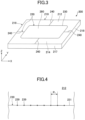
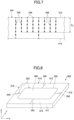
- FIGS. 4 and 5 are diagrams depicting an example of a configuration of the product line 230.
- FIG. 4 is a plan view schematically depicting a part of the product line 230 formed on the first main surface 212 of the first glass plate 200.
- FIG. 5 is a cross-sectional view schematically depicting a part of the product line 230 in the first glass plate 200.
- FIGS. 6 and 7 are diagrams depicting an example of a configuration of the release line 240.
- FIG. 6 is a plan view schematically depicting a part of the release line 240 formed on the first main surface 212 of the first glass plate 200.
- FIG. 7 is a cross-sectional view schematically depicting a part of the release line 240 in the first glass plate 200.
- FIGS. 4 and 5 show that the product line 230 includes a first in-plane void array 231 on the first main surface 212.
- the first in-plane void array 231 is configured of a plurality of in-plane voids 239 arranged on the first main surface 212.
- the product line 230 includes a plurality of internal void arrays 250 (in the following, referred to as "internal void arrays for product line 250"), each extending from the first main surface 212 of the first glass plate 200 to the second main surface 214.
- Each internal void array for product line 250 has a corresponding in-plane void 239 of the in-plane void array 231. In other words, each internal void array for product line 250 extends below a corresponding in-plane void 239.
- a plurality of internal voids 258 are arranged in the following, referred to as "internal voids for product line 258" are arranged.
- the plurality of internal voids for product line 258 are arranged in a line, thereby the internal void array for product line 250 is formed.
- the extension direction of the internal void array for product line 250 is not limited to the direction orthogonal to the first main surface 212.
- the internal void array for product line 250 may extend in a direction inclined from the thickness direction of the first glass plate 200.
- FIGS. 4 and 5 show that a distance P 1 between centers of adjacent in-plane voids 239 (spacing of in-plane voids) in the first in-plane void array 231 in the product line 230 is the same for any of the in-plane voids 239.
- the embodiment is not limited to the above-described configuration, and the distance P 1 between centers of the adjacent in-plane voids 239 may vary depending on the in-plane void 239.
- the distance P 1 between centers of the adjacent in-plane voids 239 may be small, and the distance P 1 between centers of the other adjacent in-plane voids 239 may be great.
- the distance P 1 between centers of the in-plane voids 239 is 10 um at the maximum.
- the maximum distance P 1 between centers of the in-plane voids 239 preferably falls within a range of 1 um to 10 um, more preferably falls within a range of 3 um to 8 ⁇ m, and further preferably falls within a range of 3 um to 5 ⁇ m.
- the shape of the in-plane void 239 in the top plan view is not limited to a circle, as illustrated in FIG. 4 .
- the shape of the in-plane void 239 may vary depending on the condition of irradiation and scanning of laser light.
- the shape of the internal void for product line 258 in the internal void array for product line 250 viewed in the cross-sectional view is not limited to an ellipse, as illustrated in FIG. 5 .
- the shape of the cross section of the internal void for product line 258 may vary depending on the condition of irradiation and scanning of laser light.
- FIGS. 6 and 7 show that the release line 240 includes a second in-plane void array 241 on the first main surface 212.
- the second in-plane void array 241 is configured of a plurality of in-plane voids 249 arranged on the first main surface 212.
- the second in-plane void array 241 includes a plurality of internal void arrays 260 (in the following, referred to as "internal void arrays for release line 260"), each extending from the first main surface 212 of the first glass plate 200 to the second main surface 214.
- Each internal void array for release line 260 corresponds to the in-plane void 249. In other words, each internal void array for release line 260 extends below a corresponding in-plane void 249.
- a plurality of internal voids 268 are arranged in the following, referred to as "internal voids for release line 268" are arranged.
- the plurality of internal voids for release line 268 are arranged in a line, thereby the internal void array for release line 260 is formed.
- the extension direction of the internal void array for release line 260 is not limited to the direction orthogonal to the first main surface 212.
- the internal void array for release line 260 may extend in a direction inclined from the thickness direction of the first glass plate 200.
- a length of the internal void array for product line having the maximum length among the internal void arrays for product line will be denoted as L 1max
- a length of the internal void array for product line having the minimum length among the internal void arrays for product line will be denoted as L 1min
- a length of the internal void array for release line having the maximum length among the internal void arrays for release line will be denoted as L 2max
- a length of the internal void array for release line having the minimum length among the internal void arrays for release line will be denoted as L 2min .
- FIGS. 4 and 5 show that each of the total lengths of the internal void arrays for product line 250 (in the following, denoted as "L 1 ”) is equal to the thickness t of the first glass plate 100.
- FIGS. 6 and 7 show that a part of the internal void arrays for release line 260 penetrate from the first main surface 212 to the second main surface 214, and the other internal void arrays for release line 260 do not penetrate the second main surface 214.
- the maximum total length L 2max of the internal void array for release line 260 is equal to the thickness t of the first glass plate 100, and the minimum total length L 2min (in the following, also denoted as D a ) of the internal void array for release line 260 is less than the thickness t of the first glass plate 200.
- the internal void arrays in the first glass plate 200 satisfy the above-described formulas (1) and (2).
- the length D a preferably falls within a range of 40% to 95% of the distance from the first main surface 212 to the second main surface 214, i.e. the thickness of the glass plate.
- the internal void array that does not penetrate the second main surface of the glass plate will be referred to as an "unpenetrating type internal void array”.
- the internal void array that penetrates from the first main surface to the second main surface will be particularly referred to as a "penetrating type internal void array”.
- part of the internal void arrays for release line 260 are "penetrating type internal void arrays".
- the other internal void arrays for release line 260 are "unpenetrating type internal void arrays”.
- All the internal void arrays for product line 250, illustrated in FIG. 5 are "penetrating type internal void arrays”.
- the glass article 280 is prevented from being unintentionally separated from the first glass plate 200 along the separation line 220 even if a stress is applied to the first glass plate 200, particularly to the separation line 220, i.e. the pre-separation is significantly prevented from occurring.
- the glass article 280 is separated from the first glass plate 200 in the predetermined process, i.e. the separation process. Moreover, the quality of the glass article 280 is prevented from being degraded due to scratches or cracks occurring on end faces of the glass article 280, when separated from the first glass plate 200 during handling of the first glass plate 200.
- a glass plate in which a pre-separation phenomenon is less likely to occur is provided.
- the product line 230 and the release line 240 may have any configurations.
- FIG. 5 shows that all the internal void arrays for product line 250 are penetrating type internal void arrays.
- the embodiment of the present invention is not limited to this. At least a part of the internal void arrays for product line 250 may be unpenetrating type internal void arrays.
- FIG. 7 shows that the total lengths of the unpenetrating type internal void arrays among the internal void arrays for release line 260 are constant (length D a ).
- length D a the total lengths of the unpenetrating type internal void arrays may be different from each other.
- the internal voids for product line 258 are arranged at substantially equal intervals.
- the internal voids for product line 258 may be arranged at non-equal intervals in the internal void array for product line 250.
- the internal voids for release line 268 are arranged at substantially equal intervals.
- the internal voids for release line 268 may be arranged at non-equal intervals in the internal void array for release line 260.
- FIG. 8 is a perspective view schematically depicting a glass plate according to the embodiment of the present invention (in the following, referred to as a "second glass plate").
- the second glass plate 300 has substantially the same configuration as that of the above-described first glass plate 200.
- the second glass plate 300 has a rectangular shape in the top plan view, and includes a first main surface 312 and a second main surface 314 that are opposite each other.
- the second glass plate 300 has four end faces 316 to 319 connecting the first main surface 312 and the second main surface 314.
- the second glass plate 300 has a plurality of separation lines 320 on the first main surface 312.
- the separation line 320 includes a product line 330 and a release line 340.
- the product line 330 in the second glass plate 300 has the same configuration as the product line 230 in the first glass plate 200, illustrated in FIGS. 4 and 5 .
- the reference numeral used in FIGS. 4 and 5 will be used.
- the release line 340 in the second glass plate 300 is formed by irradiating the glass plate with laser light. However, the release line 340 has a different configuration from the release line 240 in the first glass plate 200.
- FIG. 9 shows that the release line 340 includes a second in-plane void array 341 on the first main surface 312.
- the second in-plane void array 341 is configured of a plurality of in-plane voids 349 arranged on the first main surface 312.
- FIG. 10 shows that the second in-plane void array 341 includes a plurality of internal void arrays 360 (in the following, referred to as "internal void arrays for release line 360"), each extending from the first main surface 312 of the second glass plate 300 towards the second main surface 314.
- Each internal void array for release line 360 corresponds to the in-plane void 349.
- each internal void array for release line 360 extends below a corresponding in-plane void 349.
- a plurality of internal voids 368 (in the following, referred to as "internal voids for release line 368") are arranged.
- the plurality of internal voids for release line 368 are arranged in a line, thereby the internal void array for release line 360 is formed.
- the extension direction of the internal void array for release line 360 is not limited to the direction orthogonal to the first main surface 312.
- the internal void array for release line 360 may extend in a direction inclined from the thickness direction of the second glass plate 300.
- a length of the internal void array for product line having the maximum length among the internal void arrays for product line will be denoted as L 1max
- a length of the internal void array for release line having the maximum length among the internal void arrays for release line will be denoted as L 2max .
- the embodiment has a feature that a relation expressed by the following formula (3) is satisfied, i.e. L 1 max > L 2 max .
- FIGS. 9 and 10 show that each internal void array for release line 360 does not penetrate the second main surface 314, and is an "unpenetrating type internal void array".
- a total length L 2 of each of the internal void arrays for release line 360 is less than a thickness t of the second glass plate 300.
- the total lengths L 2 of the internal void arrays for release line 360 are the same length D b .
- the length D b preferably falls within a range of 40% to 95% of the distance from the first main surface 312 to the second main surface 314, i.e. the thickness of the glass plate t.
- the glass article 380 is prevented from being unintentionally separated from the second glass plate 300 along the separation line 320 even if a stress is applied to the second glass plate 300, particularly to the separation line 320, i.e. the pre-separation is significantly prevented from occurring.
- the glass article 380 is separated from the second glass plate 300 in the predetermined process, i.e. the separation process. Moreover, the quality of the glass article 380 is prevented from being degraded due to scratches or cracks occurring on end faces of the glass article 380, when separated from the second glass plate 300 during handling of the second glass plate 300.
- the configuration of the release line 340, illustrated in FIG. 9 and FIG. 10 is merely an example, and the release line 340 may have another configuration.
- FIG. 11 is a diagram schematically depicting another aspect of the release line.
- FIG. 11 is a cross-sectional view schematically depicting a part of the internal void array for release line.
- FIG. 11 shows that the release line 340A includes a second in-plane void array 341A on the first main surface 312 of the glass plate.
- the release line 340A includes the "unpenetrating type internal void array" similar to the internal void array for release line 360 shown in FIG. 10 .
- the "unpenetrating type internal void arrays" arranged along the second in-plane void array 341A in the release line 340A alternate an internal void array that does not penetrate the first main surface 312 and an internal void array that does not penetrate the second main surface 314, different from the release line 340 illustrated in FIG. 10 .
- a length of a range of extension of the internal void array for release line 360A-1 in the thickness direction of the glass plate will be denoted by D c
- a length of a range of extension of the internal void array for release line 360A-2 in the thickness direction will be denoted by D d .
- the lengths D c and D d preferably fall within a range of 40% to 95% of the distance between the first main surface 312 and the second main surface 314 (i.e. the thickness of the glass plate t).
- the lengths D c and D d are not required to be the same, and may be different from each other.
- the lengths D c of the internal void arrays for release line 360A-1 may be different from each other.
- the lengths D d of the internal void arrays for release line 360A-2 may be different from each other.
- the release line 340A illustrated in FIG. 11 , has the above-described configuration in which the internal void array for release line 360A-1 and the internal void array for release line 360A-2 are alternated along a predetermined direction.
- the pattern of alternating arrangement of the internal void array for release line 360A-1 and the internal void array for release line 360A-2 is not limited to this.
- a plurality of internal void arrays for release line 360A-1 may be successively arranged followed by one internal void array for release line 360A-2 along a predetermined direction
- a plurality of internal void arrays for release line 360A-2 may be successively arranged followed by one internal void array for release line 360A-1
- a plurality of internal void arrays for release line 360A-1 may be successively arranged followed by a plurality of internal void arrays for release line 360A-2.
- the internal void array for release line 360A-1 and the internal void array for release line 360A-2 may be aperiodically arranged along a predetermined direction.
- FIG. 12 is a diagram schematically depicting another aspect of the release line.
- FIG. 12 is a cross-sectional view schematically illustrating a part of the internal void arrays for release line.
- FIG. 12 shows that the release line 340B does not include a second in-plane void array on either of the first main surface 312 or the second main surface 314 of the glass plate.
- An in-plane void is not present on either of the first main surface 312 or the second main surface 314.
- the release line 340B is not viewable from the first main surface 312 side or the second main surface 314 side of the second glass plate 300.
- the release line 340B is a "virtual" line.
- the "virtual" release line 340B will be described later.
- the release line 340B includes internal void arrays for release line 360B arranged on a plurality of lines connecting the first main surface 312 and the second main surface 314 in the second glass plate 300.
- the internal void array for release line 360B includes a plurality of internal voids for release line 368.
- a length of a range of extension of the internal void array for release line 360B in the thickness direction of the glass plate, illustrated in FIG. 12 , will be denoted by D e .
- the length D e preferably falls within a range of 400 to 95% of the distance between the first main surface 312 and the second main surface 314 (i.e. the thickness of the second glass plate 300 t).
- Intervals between the adjacent internal voids for release line 368 in the internal void array for release line 360B are constant. Moreover, the intervals in all the internal void arrays for release line 360B are the same.
- the embodiment of the present invention is not limited to this, and the intervals between the adjacent internal voids for release line 268 in the internal void array for release line 360B may be different from each other. Furthermore, the pattern of arrangement of the internal voids for release line 368 in the internal void arrays for release line 360B may be different from each other.
- the release line 340B having the above-described configuration prevents the pre-separation from occurring.
- the product line 330 and the release line 340 may have any configurations.
- FIG. 10 shows that all the internal void arrays for release line 360 have the same total length D b . However, the total lengths of the internal void arrays for release line 360 may be different from each other.
- the internal voids for release line 368 are arranged at substantially equal intervals.
- the internal voids for release line 368 may be arranged at non-equal intervals in the interval void array for release line 360.
- the in-plane voids 349 are present on the first main surface 312. However, the in-plane voids 349 correspond only to the internal void arrays for release line 360A-1. An in-plane void corresponding to the internal void array for release line 360A-2 is not present on the first main surface 312.
- in-plane voids 349 corresponding to the internal void arrays for release line may not be present in appearance on the first main surface 312.
- an in-plane void is assumed to be virtually present (in the following, referred to as a "virtual in-plane void") at a point where an extension line, extending in the thickness direction from the internal void array for release line included in the glass plate to the first main surface 312, crosses with the first main surface 312.
- the "virtual in-plane voids" are assumed to be arranged, to form a second in-plane void array for release line.
- the in-plane void on the first main surface 312 is assumed to be a "virtual in-plane void" configuring a part of the second in-plane void array for release line.
- the configuration of the release line 240 in the first glass plate 200 can be combined with the configurations of the release lines 340, 340A, and 340B in the second glass plate 300.
- the unpenetrating type internal void arrays may be "alternatingly arranged" as illustrated in FIG. 11 .
- some of the unpenetrating type internal void arrays in the release line 240 illustrated in FIG. 7 may be unpenetrating type internal void arrays that do not have in-plane voids.
- first glass plate 200 As an example. It is obvious for a person skilled in the art that the following description can be applied directly or with a modification also to the second glass plate 300.
- compositions of the first glass plate 200 are not particularly limited.
- the first glass plate 200 may be made of, for example, a soda lime glass or an alkali aluminosilicate glass.
- the shape of the first glass plate 200 is not particularly limited.
- the first glass plate 200 may have an approximately rectangular shape, or an approximately circular shape.
- the thickness of the first glass plate 200 is not particularly limited. The thickness may fall within a range of 0.03 mm to 6 mm. When the first glass plate 200 is used in a building or a house, or installed in a vehicle, the thickness of the first glass plate 200 may fall within a range of 2 mm to 19 mm, for example.
- the first glass plate 200 may be a chemically tempered glass.
- an end face of the glass article 280 separated from the first glass plate 200 is chemically tempered.
- the product line 230 illustrated in FIG. 3 has a shape of a single loop.
- the number of product lines 230 and the shape are not particularly limited to this.
- the product line 230 may include four lines, as illustrated in FIG. 1 .
- the product line 230 may have another shape. 0131
- FIG. 3 shows that one glass article 280 is extracted from one first glass plate 200.
- the embodiment is not limited to this, and a plurality of glass articles 280 may be extracted from one first glass plate 200.
- FIG. 4 shows that the product line 230 includes the plurality of in-plane voids 239 on the first surface 212 of the first glass plate 200.
- the product line 230 may also include a plurality of in-plane voids on the second surface 214 of the first glass plate 200. In this case, the glass article 280 is more easily separated from the first glass plate 200.
- the maximum distance P 1 between centers of the adjacent in-plane voids 239 is 10 um or less.
- an interval between the adjacent internal voids for product line 258, i.e. a distance between a lower end of an upper internal void for product line 258 and an upper end of a lower internal void for product line 258, preferably falls within a range of 0 to 50 um, more preferably 0 to 20 ⁇ m, and further preferably 0 to 10 um.
- the glass article 280 is more easily separated from the first glass plate 200, and the end face of the glass article 280 becomes smoother.
- FIG. 3 shows that the release lines 240 include four lines each extending in a longitudinal direction (Y-axis direction) or in a lateral direction (X-axis direction) on the first main surface 212.
- the number and the shape of release lines are not particularly limited.
- the release lines 240 may include lines arranged on the same lines as the product lines 230.
- the release line 240 may include a curve or two or more curves.
- the release line 240 may have another shape.
- the release line 240 in the above-described example includes the plurality of in-plane voids 249 on the first main surface 212 of the first glass plate 200.
- the release line may also include a plurality of in-plane voids on the second surface 214 of the first glass plate 200.
- the distances P 2 between centers of adjacent in-plane voids 249 on the release line 240 are constant.
- the distance P 2 between centers of adjacent in-plane voids 249 may vary depending on the in-plane voids 249.
- the distance P 2 between centers of adjacent in-plane voids 249 may be relatively small, and the distance P 2 between centers of the other adjacent in-plane voids 249 may be relatively great.
- the distance P 2 between centers of adjacent in-plane voids 249 is 25 um or less at the maximum.
- the distance P 2 between centers of adjacent in-plane voids 249 preferably falls within a range of 3 um to 20 ⁇ m.
- the first glass plate 200 When the maximum value of the distance between centers P 2 is 20 ⁇ m or less, as described later in detail, by irradiating the first glass plate 200 with a CO 2 laser light along the separation line 220, the first glass plate 200 is separated at the positions of the product line 230 and the release line 240. Thus, in the separation process for the first glass plate 200, the problem that the glass article 280 cannot be properly separated from the first glass plate 200 is less likely to occur.
- the distance P 1 and the distance P 2 may be substantially the same.
- the shape of the in-plane void 249 in the top plan view is not limited to a circle, as illustrated in FIG. 6 .
- the shape of the in-plane void 249 may vary depending on the condition of irradiation and scanning of laser light. Furthermore, as described above, the in-plane void 249 may not be present on the release line 240.
- the shape of the internal void for release line 268 in the internal void array for release line 260 viewed in the cross-sectional view is not limited to an ellipse, as illustrated in FIG. 7 .
- the shape of the cross section of the internal void for release line 268 may vary depending on the condition of irradiation and scanning of laser light.
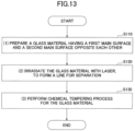
- FIG. 13 is a flowchart schematically depicting an example of a flow of the manufacturing method of a glass plate according to the embodiment of the present invention (in the following, referred to as a "first manufacturing method").
- FIG. 13 shows that the first manufacturing method includes:
- step S130 in the first manufacturing method is not indispensable, and performed as necessary.
- a glass material is prepared.
- the glass material has a first main surface and a second main surface.
- the glass material may be a soda lime glass, an alkali aluminosilicate glass or the like.
- a thickness of the glass material is not particularly limited. The thickness may fall within a range of 0.03 mm to 6 mm, for example. When the glass material is used for a building or a house, or installed in a vehicle, the thickness of the glass material may fall within a range of 2 mm to 19 mm.
- the glass material may be provided in a plate shape, or in a roll shape.
- a glass material of roll shape has an advantage of easy conveyance, compared with a glass material of plate shape.
- the first main surface and the second main surface of the glass material of plate shape are not necessarily flat, and may be curved.
- the glass material of plate shape is not particularly limited.
- the glass material may have a rectangular shape, a circular shape, an elliptic shape or the like. In the following the glass material having a rectangular shape will be described as an example.
- FIG. 14 is a perspective view schematically depicting the glass material having a rectangular shape. 0154
- FIG. 14 shows that the glass material 410 has a first main surface 412, a second main surface 414, and four end faces 416 to 419.
- the first main surface 412 for example, of the glass material 410 is irradiated with laser light. Thus, a separation line is formed on the first main surface 412 of the glass material 410.
- FIG. 15 is a perspective view schematically depicting an example of the glass material 410 with a separation line 420 formed on the first main surface 412. 0157
- FIG. 15 shows that the separation line 420 includes the product line 430 and release lines 40.
- the product lines 430 include four lines extending in the longitudinal direction (Y-axis direction) or in the lateral direction (X-axis direction) formed approximately at the center of the first main surface 412.
- the release lines 440 include eight lines, each extending from an end of the product line 430 to any of the end faces 416 to 419 of the glass material 410. From approximately the central part of the glass material 410, on which the separation line 420 is formed, a glass article 480 defined by the product lines 430 is separated in the separation process, which will be described below.
- the product line 430 includes a first in-plane void array formed by arranging a plurality of in-plane voids present on the first main surface 412; and an internal void array for product line extending in the plate thickness direction, with respect to each of the in-plane voids (not shown in FIG. 15 ).
- the release line 440 includes a second in-plane void array formed by arranging a plurality of in-plane voids present on the first main surface 412; and an internal void array for release line extending in the plate thickness direction, with respect to each of the in-plane voids (not shown in FIG. 15 ).
- the shape of the separation line 420 i.e. the shape of the product line 430 and the shape of the release line 440 are not particularly limited.
- the release line 440 may not be viewable from outside, such as the release line 340B illustrated in FIG. 12 .
- a length of the internal void array for product line having the maximum length among the internal void arrays for product line will be denoted as L 1max
- a length of the internal void array for product line having the minimum length among the internal void arrays for product line will be denoted as L 1min
- a length of the internal void array for release line having the maximum length among the internal void arrays for release line will be denoted as L 2max
- a length of the internal void array for release line having the minimum length among the internal void arrays for release line will be denoted as L 2min .
- the separation line 420 is formed so that the following formula (3) is satisfied L 1 max > L 2 max .
- a laser device for forming the separation line 420 is, for example, a short pulse laser device that emits a laser light with a pulse width of the order of femtoseconds to the order of nanoseconds, i.e. the range of 1.0 ⁇ 10 -15 to 9.9 ⁇ 10 -9 seconds.
- the short pulse laser light is preferably burst pulses.
- An average power of the laser light within an irradiation period is, for example, 30 W or more. When the average power of the short pulse laser light is less than 10 W, a sufficient internal void may not be formed.
- a short pulse laser device used for forming an internal void array is, for example, a burst laser device with a burst number of 3 to 10, a laser output power of about 90% of the rated output (50 W), a burst frequency of about 60 kHz, and a time width of burst that falls within a range of 20 picoseconds to 165 nanoseconds.
- the time width of burst preferably falls within a range of 10 nanoseconds to 100 nanoseconds.
- a method of irradiating the glass material with laser light includes a method using a self-focusing phenomenon based on the Kerr-effect; a method using Gaussian Bessel beam with an axicon lens; a method using a linear focus forming beam by an aberration lens; or the like.
- a condition for irradiation with laser light is not particularly limited, as long as the separation line 420 is formed.
- step S120 After the process of step S120, a glass plate having the separation line 420 is produced.
- the first manufacturing method provides a glass plate in which a pre-separation is less likely to occur.
- a glass plate according to the embodiment of the present invention is produced.
- the first manufacturing method may include a chemical tempering process after the process of step S120.
- a typical chemical tempering process is performed by immersing a glass material to be processed in a molten salt containing alkali metal ions.
- a temperature of the molten salt during the chemical tempering process falls within a range of 430 °C to 500 °C, for example.
- the glass material is exposed to the molten salt at a high temperature.
- step S110 and step S120 in the first manufacturing process has the above-described feature, a pre-separation is less likely to occur even if the glass plate is exposed to the molten salt at the high temperature in the chemical tempering process.
- the above-described separation line 420 is formed, by irradiating with laser light, in the glass material 410 to be subjected to the chemical tempering process.
- a molten salt enters an internal void array for product line through the in-plane void array, and a region defined by the in-plane void array of the product line 430 and the internal void array for product line, i.e. an end face of the glass article 480, is also chemically tempered.
- the glass article 480 is separated and extracted from the glass plate produced by the first manufacturing method, in a separation process after the process of the first manufacturing method.
- the glass article 480 is required to be properly separated from the glass plate.
- a CO 2 laser device is typically used in the separation process.
- the maximum distance P 2max between centers of the adjacent in-plane voids in the release line 440 is adjusted so as to fall within a range of 3 um to 20 ⁇ m.
- the glass plate is irradiated with CO 2 laser light along the separation line 420, the glass plate is properly divided at the product line 430 and at the release line 440.
- the problem that the glass article 480 cannot be separated from the glass plate in the separation process is less likely to occur for the glass plate produced by using the first manufacturing method.
- a glass plate in which a pre-separation is less likely to occur, and from which a glass article is easily separated in a required process, i.e. the separation process, is produced.
Landscapes
- Engineering & Computer Science (AREA)
- Optics & Photonics (AREA)
- Physics & Mathematics (AREA)
- Chemical & Material Sciences (AREA)
- Mechanical Engineering (AREA)
- Plasma & Fusion (AREA)
- Chemical Kinetics & Catalysis (AREA)
- General Chemical & Material Sciences (AREA)
- Organic Chemistry (AREA)
- Materials Engineering (AREA)
- Oil, Petroleum & Natural Gas (AREA)
- Life Sciences & Earth Sciences (AREA)
- Geochemistry & Mineralogy (AREA)
- Health & Medical Sciences (AREA)
- Toxicology (AREA)
- Re-Forming, After-Treatment, Cutting And Transporting Of Glass Products (AREA)
- Surface Treatment Of Glass (AREA)
- Laser Beam Processing (AREA)
- Packaging Frangible Articles (AREA)
Claims (15)
- Glasplatte, die eine erste Hauptoberfläche (12, 102, 212, 312, 412) und eine zweite Hauptoberfläche (14, 104, 214, 314, 414), die einander gegenüberliegen, aufweist,wobei eine Vielzahl von Trennlinien (20, 220, 320, 420) in der Glasplatte und auf der ersten Hauptoberfläche (12, 102, 212, 312, 412) durch Bestrahlung der Glasplatte mit Laserlicht gebildet sind,wobei die Trennlinien (20, 220, 320, 420) aus mindestens einer Produktlinie (30, 230, 330, 430) und mindestens einer Ablöselinie (32, 240, 340, 340A, 340B, 440) gestaltet sind; wobei die Produktlinie (30, 230, 330, 430) einem Umriss eines Glasartikels (80, 280, 380, 480) entspricht, der von der Glasplatte abgetrennt und entnommen werden soll; und wobei die Ablöselinie (32, 240, 340, 340A, 340B, 440) ein anderer Teil der Trennlinien (20, 220, 320, 420) als die Produktlinie (30, 230, 330, 430) ist,wobei die Produktlinie (30, 230, 330, 430) eine erste in der Ebene liegende Hohlraumanordnung (231) enthält, die aus einer Vielzahl von in der Ebene liegenden Hohlräumen (139, 239, 249, 349) gestaltet ist, die auf der ersten Hauptoberfläche (12, 102, 212, 312, 412) angeordnet sind; die Produktlinie (30, 230, 330, 430) weiter eine Vielzahl von inneren Hohlraumanordnungen für die Produktlinie (250) enthält, die jeweils einen in der Ebene liegenden Hohlraum (139, 239, 249, 349) der ersten in der Ebene liegenden Hohlraumanordnung (231) aufweisen und sich von der ersten Hauptoberfläche (12, 102, 212, 312, 412) in Richtung der zweiten Hauptoberfläche (14, 104, 214, 314, 414) erstrecken; und die innere Hohlraumanordnung für die Produktlinie (250) aus einer Vielzahl von inneren Hohlräumen für die Produktlinie (258) gestaltet ist, wobei die Ablöselinie (32, 240, 340, 340A, 340B, 440) eine innere Hohlraumanordnung für die Ablöselinie (260, 360, 360A-1, 360A-2, 360B) enthält, die entlang jeder einer Mehrzahl von Linien angeordnet ist, welche die erste Hauptoberfläche (12, 102, 212, 312, 412) und die zweite Hauptoberfläche (14, 104, 214, 314, 414) verbinden; und die innere Hohlraumanordnung für die Ablöselinie (260, 360, 360A-1, 360A-2, 360B) aus einer Vielzahl von inneren Hohlräumen für die Ablöselinie (268, 368) gestaltet ist, und(i) wobei eine Länge der inneren Hohlraumanordnung für die Produktlinie (250), die eine maximale Länge unter den inneren Hohlraumanordnungen für die Produktlinie (250) L1max aufweist, gleich einer Länge der inneren Hohlraumanordnung für die Ablöseleitung (260, 360, 360A-1, 360A-2, 360B), die eine maximale Länge unter den inneren Hohlraumanordnungen für die Ablöselinie (260, 360, 360A-1, 360A-2, 360B) L2max aufweist, ist; und eine Länge der inneren Hohlraumanordnung für die Produktlinie (250), die eine minimalen Länge unter den inneren Hohlraumanordnungen für die Produktlinie (250) L1min aufweist, größer als eine Länge der innerer Hohlraumanordnung für die Ablöseleitung (260, 360, 360A-1, 360A-2, 360B), die eine minimalen Länge unter den inneren Hohlraumanordnungen für die Ablöseleitung (260, 360, 360A-1, 360A-2, 360B) L2min aufweist, ist, oder(ii) die Länge L1max größer ist als die Länge L2max.
- Glasplatte nach Anspruch 1,wobei (ii) die Länge L1max größer ist als die Länge L2max, undwobei die Länge L1min größer als L2min ist.
- Glasplatte nach Anspruch 1 oder 2,
wobei ein Abstand P1 zwischen den Zentren der in der Ebene liegenden Hohlräume (139, 239, 249, 349) der ersten in der Ebene liegenden Hohlraumanordnung (231), die einander benachbart sind, in einen Bereich von 1 µm bis 10 µm fällt. - Glasplatte nach einem der Ansprüche 1 bis 3,
wobei ein Abstand P2 zwischen den Zentren virtueller in der Ebene liegender Hohlräume (139, 239, 249, 349), die einander benachbart sind, in einen Bereich von 3 µm bis 25 µm fällt, wobei der virtuelle in der Ebene liegende Hohlraum (139, 239, 249, 349) als eine Position definiert ist, an der eine Verlängerungslinie, die von der inneren Hohlraumanordnung für die Ablöselinie (260, 360, 360A-1, 360A-2, 360B) verlängert ist, die erste Hauptoberfläche (12, 102, 212, 312, 412) oder einen Hohlraum in der inneren Hohlraumanordnung für die Ablöselinie (260, 360, 360A-1, 360A-2, 360B) auf der ersten Hauptoberfläche (12, 102, 212, 312, 412) kreuzt, wenn sich der Hohlraum auf der ersten Hauptoberfläche (12, 102, 212, 312, 412) befindet. - Glasplatte nach einem der Ansprüche 1 bis 4,
wobei mindestens eine der inneren Hohlraumanordnungen für die Ablöselinie (260, 360, 360A-1, 360A-2, 360B) einen in der Ebene liegenden Hohlraum (139, 239, 249, 349) auf der ersten Hauptoberfläche (12, 102, 212, 312, 412) aufweist. - Glasplatte nach Anspruch 5,
wobei mindestens eine der inneren Hohlraumanordnungen für die Ablöselinie (260, 360, 360A-1, 360A-2, 360B) einen in der Ebene liegenden Hohlraum (139, 239, 249, 349) auf der ersten Hauptoberfläche (12, 102, 212, 312, 412) und einen in der Ebene liegenden Hohlraum (139, 239, 249, 349) auf der zweiten Hauptoberfläche (14, 104, 214, 314, 414) aufweist. - Glasplatte nach Anspruch 5,wobei die inneren Hohlraumanordnungen für die Ablöselinie (260, 360, 360A-1, 360A-2, 360B) eine erste innere Hohlraumanordnung für die Ablöselinie (260, 360, 360A-1, 360A-2, 360B), eine zweite innere Hohlraumanordnung für die Ablöselinie (260, (260, 360, 360A-1, 360A-2, 360B) und eine dritte innere Hohlraumanordnung für die Ablöselinie (260, 360, 360A-1, 360A-2, 360B), enthalten, die entlang einer vorbestimmten Richtung in der ersten Hauptoberfläche (12, 102, 212, 312, 412) in dieser Reihenfolge angeordnet sind, undwobei die erste innere Hohlraumanordnung für die Ablöselinie (260, 360, 360A-1, 360A-2, 360B) einen in der Ebene liegenden Hohlraum (139, 239, 249, 349) auf der ersten Hauptoberfläche (12, 102, 212, 312, 412) aufweist und keinen in der Ebene liegenden Hohlraum (139, 239, 249, 349) auf der zweiten Hauptoberfläche (14, 104, 214, 314, 414) aufweist; die zweite innere Hohlraumanordnung für die Ablöselinie (260, 360, 360A-1, 360A-2, 360B) keinen in der Ebene liegenden Hohlraum (139, 239, 249, 349) auf der ersten Hauptoberfläche (12, 102, 212, 312, 412) aufweist und einen in der Ebene liegenden Hohlraum (139, 239, 249, 349) auf der zweiten Hauptoberfläche (14, 104, 214, 314, 414) aufweist; und die dritte innere Hohlraumanordnung für die Ablöselinie (260, 360, 360A-1, 360A-2, 360B) einen in der Ebene liegenden Hohlraum (139, 239, 249, 349) auf der ersten Hauptoberfläche (12, 102, 212, 312, 412) aufweist und keinen in der Ebene liegenden Hohlraum (139, 239, 249, 349) auf der zweiten Hauptoberfläche (14, 104, 214, 314, 414) aufweist.
- Glasplatte nach einem der Ansprüche 1 bis 4,wobei die Ablöselinie (32, 240, 340, 340A, 340B, 440) eine zweite in der Ebene liegende Hohlraumanordnung (241, 341, 341A) auf der ersten Hauptoberfläche (12, 102, 212, 312, 412) aufweist, undwobei die inneren Hohlraumanordnungen für die Ablöselinie (260, 360, 360A-1, 360A-2, 360B) in der Ebene liegende Hohlräume (139, 239, 249, 349) auf der ersten Hauptoberfläche (12, 102, 212, 312, 412) aufweisen, wobei die in der Ebene liegenden Hohlräume (139, 239, 249, 349) der inneren Hohlraumanordnungen (150) die zweite in der Ebene liegende Hohlraumanordnung (241, 341, 341A) gestalten.
- Glasplatte nach Anspruch 8,
wobei die in der Ebene liegenden Hohlräume (139, 239, 249, 349), welche die zweite in der Ebene liegende Hohlraumanordnung (241, 341, 341A) gestalten, in im Wesentlichen gleichen Abständen auf der ersten Hauptoberfläche (12, 102, 212, 312, 412) angeordnet sind. - Glasplatte nach einem der Ansprüche 1 bis 9,
wobei die in der Ebene liegenden Hohlräume (139, 239, 249, 349), welche die erste in der Ebene liegende Hohlraumanordnung (231) gestalten, in im Wesentlichen gleichen Abständen auf der ersten Hauptoberfläche (12, 102, 212, 312, 412) angeordnet sind. - Glasplatte nach einem der Ansprüche 1 bis 10,
wobei jede der inneren Hohlraumanordnungen für die Produktlinie (250) einen in der Ebene liegenden Hohlraum auf der zweiten Hauptoberfläche (14, 104, 214, 314, 414) aufweist. - Glasplatte nach einem der Ansprüche 1 bis 11,
wobei die Trennlinien (20, 220, 320, 420) einen gekrümmten Teil aufweisen oder im Wesentlichen aus geraden Linien gestaltet sind. - Glasplatte nach einem der Ansprüche 1 bis 12,
wobei die Glasplatte chemisch vorgespannt ist. - Verfahren zur Herstellung einer Glasplatte, umfassend:Herstellen eines Glasmaterials (101, 410), das eine erste Hauptoberfläche (12, 102, 212, 312, 412) und eine zweite Hauptoberfläche (14, 104, 214, 314, 414), die einander gegenüberliegen, aufweist; undBestrahlen des Glasmaterials (101, 410) mit Laserlicht, um Trennlinien (20, 220, 320, 420) zu bilden,wobei die Trennlinien (20, 220, 320, 420) aus mindestens einer Produktlinie (30, 230, 330, 430) und mindestens einer Ablöselinie (32, 240, 340, 340A, 340B, 440) gestaltet sind; wobei die Produktlinie (30, 230, 330, 430) einem Umriss eines Glasartikels (80, 280, 380, 480) entspricht, der von dem Glasmaterial abgetrennt und entnommen werden soll; und wobei die Ablöselinie (32, 240, 340, 340A, 340B, 440) ein anderer Teil der Trennlinien (20, 220, 320, 420) als die Produktlinie (30, 230, 330, 430) ist,wobei die Produktlinie (30, 230, 330, 430) eine erste in der Ebene liegende Hohlraumanordnung (231) enthält, die aus einer Vielzahl von in der Ebene liegenden Hohlräumen (139, 239, 249, 349) gestaltet ist, die auf der ersten Hauptoberfläche (12, 102, 212, 312, 412) angeordnet sind; die Produktlinie (30, 230, 330, 430) weiter eine Vielzahl von inneren Hohlraumanordnungen für die Produktlinie (250) enthält, die jeweils einen in der Ebene liegenden Hohlraum (139, 239, 249, 349) der ersten in der Ebene liegenden Hohlraumanordnung (231) aufweisen und sich von der ersten Hauptoberfläche (12, 102, 212, 312, 412) in Richtung der zweiten Hauptoberfläche (14, 104, 214, 314, 414) erstrecken; und die innere Hohlraumanordnung für die Produktlinie (250) aus einer Vielzahl von inneren Hohlräumen für die Produktlinie (258) gestaltet ist, wobei die Ablöselinie (32, 240, 340, 340A, 340B, 440) eine innere Hohlraumanordnung für die Ablöselinie (260, 360, 360A-1, 360A-2, 360B) enthält, die entlang jeder einer Mehrzahl von Linien angeordnet ist, welche die erste Hauptoberfläche (12, 102, 212, 312, 412) und die zweite Hauptoberfläche (14, 104, 214, 314, 414) verbinden; und die innere Hohlraumanordnung für die Ablöselinie (260, 360, 360A-1, 360A-2, 360B) aus einer Vielzahl von inneren Hohlräumen für die Ablöselinie (268, 368) gestaltet ist, und(i) wobei eine Länge der inneren Hohlraumanordnung für die Produktlinie (250), die eine maximale Länge unter den inneren Hohlraumanordnungen für die Produktlinie (250) L1max aufweist, gleich einer Länge der inneren Hohlraumanordnung für die Ablöseleitung (260, 360, 360A-1, 360A-2, 360B), die eine maximale Länge unter den inneren Hohlraumanordnungen für die Ablöselinie (260, 360, 360A-1, 360A-2, 360B) L2max aufweist, ist; und eine Länge der inneren Hohlraumanordnung für die Produktlinie (250), die eine minimalen Länge unter den inneren Hohlraumanordnungen für die Produktlinie (250) L1min aufweist, größer als eine Länge der innerer Hohlraumanordnung für die Ablöseleitung (260, 360, 360A-1, 360A-2, 360B), die eine minimalen Länge unter den inneren Hohlraumanordnungen für die Ablöseleitung (260, 360, 360A-1, 360A-2, 360B) L2min aufweist, ist, oder(ii) die Länge L1max größer ist als die Länge L2max.
- Verfahren zur Herstellung einer Glasplatte nach Anspruch 14, weiter umfassend: Durchführen eines chemischen Härtungsprozesses für das Glasmaterial (101, 410) nach dem Bestrahlen des Glasmaterials (101, 410) mit Laserlicht.
Applications Claiming Priority (2)
| Application Number | Priority Date | Filing Date | Title |
|---|---|---|---|
| JP2017030506 | 2017-02-21 | ||
| PCT/JP2018/002937 WO2018155099A1 (ja) | 2017-02-21 | 2018-01-30 | ガラス板およびガラス板の製造方法 |
Publications (3)
| Publication Number | Publication Date |
|---|---|
| EP3587366A1 EP3587366A1 (de) | 2020-01-01 |
| EP3587366A4 EP3587366A4 (de) | 2020-12-02 |
| EP3587366B1 true EP3587366B1 (de) | 2023-09-13 |
Family
ID=63252654
Family Applications (1)
| Application Number | Title | Priority Date | Filing Date |
|---|---|---|---|
| EP18756881.1A Active EP3587366B1 (de) | 2017-02-21 | 2018-01-30 | Glasplatte und herstellungsverfahren für glasplatte |
Country Status (5)
| Country | Link |
|---|---|
| US (1) | US11524367B2 (de) |
| EP (1) | EP3587366B1 (de) |
| JP (1) | JP6531877B2 (de) |
| CN (1) | CN110291051B (de) |
| WO (1) | WO2018155099A1 (de) |
Families Citing this family (3)
| Publication number | Priority date | Publication date | Assignee | Title |
|---|---|---|---|---|
| EP3521254A1 (de) * | 2018-02-06 | 2019-08-07 | AGC Glass Europe | Verfahren zur herstellung eines beschichteten chemisch verstärkten glasartikels |
| DE102018126381A1 (de) * | 2018-02-15 | 2019-08-22 | Schott Ag | Verfahren und Vorrichtung zum Einfügen einer Trennlinie in ein transparentes sprödbrüchiges Material, sowie verfahrensgemäß herstellbares, mit einer Trennlinie versehenes Element |
| CN114131212A (zh) * | 2021-11-10 | 2022-03-04 | 江苏大学 | 一种透明材料封闭实心结构的激光改质切割与自动分离的方法 |
Family Cites Families (52)
| Publication number | Priority date | Publication date | Assignee | Title |
|---|---|---|---|---|
| JP2004217492A (ja) * | 2003-01-17 | 2004-08-05 | Murakami Corp | ガラス板材の切抜方法 |
| US20060246299A1 (en) | 2005-04-29 | 2006-11-02 | Brady Michael D | Methods for protecting glass |
| US20060246302A1 (en) | 2005-04-29 | 2006-11-02 | Brady Michael D | Methods for protecting glass |
| JP4998723B2 (ja) | 2007-06-18 | 2012-08-15 | 信越化学工業株式会社 | 含フッ素コーティング剤組成物 |
| US20090040640A1 (en) | 2007-08-07 | 2009-02-12 | Jinnam Kim | Glass cutting method, glass for flat panel display thereof and flat panel display device using it |
| JP2009120727A (ja) | 2007-11-15 | 2009-06-04 | Konica Minolta Holdings Inc | 撥水・防汚性物品、それを用いて構成された建築用窓ガラス、車両用窓ガラス、ディスプレイ部材、光学部品 |
| JP5055383B2 (ja) * | 2007-12-27 | 2012-10-24 | 三星ダイヤモンド工業株式会社 | 脆性材料基板のクラック形成方法 |
| EP2252557A4 (de) | 2008-02-05 | 2013-07-03 | Corning Inc | Beschädigungsresistenter glasartikel zur verwendung als abdeckplatte in elektronischen vorrichtungen |
| US8539795B2 (en) | 2009-05-13 | 2013-09-24 | Corning Incorporated | Methods for cutting a fragile material |
| TWI517922B (zh) | 2009-05-13 | 2016-01-21 | 康寧公司 | 切割脆性材料之方法 |
| WO2011002089A1 (ja) * | 2009-07-03 | 2011-01-06 | 旭硝子株式会社 | 脆性材料基板の割断方法及び割断装置並びにその割断方法により得られる車両用窓ガラス |
| CN102612499B (zh) | 2009-09-24 | 2016-08-17 | 株式会社Ihi检查计测 | 脆性工件的切割方法及切割装置 |
| US8525073B2 (en) * | 2010-01-27 | 2013-09-03 | United Technologies Corporation | Depth and breakthrough detection for laser machining |
| EP2593266A4 (de) | 2010-07-12 | 2017-04-26 | Rofin-Sinar Technologies, Inc. | Verfahren zur materialbearbeitung mittels laserfilamentierung |
| US8539794B2 (en) | 2011-02-01 | 2013-09-24 | Corning Incorporated | Strengthened glass substrate sheets and methods for fabricating glass panels from glass substrate sheets |
| JPWO2012153781A1 (ja) | 2011-05-10 | 2014-07-31 | 旭硝子株式会社 | フッ素含有有機ケイ素化合物薄膜の製造方法、及び、製造装置 |
| US9944554B2 (en) | 2011-09-15 | 2018-04-17 | Apple Inc. | Perforated mother sheet for partial edge chemical strengthening and method therefor |
| CN103509422B (zh) | 2012-06-29 | 2018-07-31 | 3M创新有限公司 | 一种疏水和疏油的涂层组合物 |
| TW201417928A (zh) * | 2012-07-30 | 2014-05-16 | Raydiance Inc | 具訂製邊形及粗糙度之脆性材料切割 |
| US9610653B2 (en) | 2012-09-21 | 2017-04-04 | Electro Scientific Industries, Inc. | Method and apparatus for separation of workpieces and articles produced thereby |
| JP2014065624A (ja) | 2012-09-25 | 2014-04-17 | Nippon Electric Glass Co Ltd | 強化ガラス基板の製造方法 |
| JP5913608B2 (ja) | 2012-09-28 | 2016-04-27 | Hoya株式会社 | 電子機器用カバーガラス及びその製造方法 |
| US9346706B2 (en) | 2012-11-29 | 2016-05-24 | Corning Incorporated | Methods of fabricating glass articles by laser damage and etching |
| WO2014085660A1 (en) | 2012-11-29 | 2014-06-05 | Corning Incorporated | Sacrificial cover layers for laser drilling substrates and methods thereof |
| US10117806B2 (en) | 2012-11-30 | 2018-11-06 | Corning Incorporated | Strengthened glass containers resistant to delamination and damage |
| US9701564B2 (en) | 2013-01-15 | 2017-07-11 | Corning Incorporated | Systems and methods of glass cutting by inducing pulsed laser perforations into glass articles |
| US9919380B2 (en) | 2013-02-23 | 2018-03-20 | Coherent, Inc. | Shaping of brittle materials with controlled surface and bulk properties |
| JP2016520501A (ja) * | 2013-03-15 | 2016-07-14 | キネストラル テクノロジーズ,インク. | レーザ切断強化ガラス |
| KR101857335B1 (ko) | 2013-04-04 | 2018-05-11 | 엘피케이에프 레이저 앤드 일렉트로닉스 악티엔게젤샤프트 | 기판 안으로 관통 개구부들을 도입하기 위한 방법 및 장치, 그리고 이렇게 제조된 기판 |
| WO2014161535A2 (de) | 2013-04-04 | 2014-10-09 | Lpkf Laser & Electronics Ag | Verfahren und vorrichtung zum trennen eines substrates |
| JP2014224892A (ja) | 2013-05-16 | 2014-12-04 | 旭硝子株式会社 | 裏面筐体 |
| JP2016135491A (ja) * | 2013-05-17 | 2016-07-28 | 旭硝子株式会社 | 放電補助式レーザ孔加工方法 |
| US9517929B2 (en) | 2013-11-19 | 2016-12-13 | Rofin-Sinar Technologies Inc. | Method of fabricating electromechanical microchips with a burst ultrafast laser pulses |
| WO2015080043A1 (ja) | 2013-11-26 | 2015-06-04 | 旭硝子株式会社 | ガラス部材およびガラス部材の製造方法 |
| JP6213190B2 (ja) | 2013-11-28 | 2017-10-18 | 日本電気硝子株式会社 | 強化ガラス板、及び強化ガラス板の製造方法 |
| US20150166393A1 (en) | 2013-12-17 | 2015-06-18 | Corning Incorporated | Laser cutting of ion-exchangeable glass substrates |
| US10442719B2 (en) | 2013-12-17 | 2019-10-15 | Corning Incorporated | Edge chamfering methods |
| WO2015113026A2 (en) | 2014-01-27 | 2015-07-30 | Corning Incorporated | Edge chamfering by mechanically processing laser cut glass |
| TW201540405A (zh) | 2014-01-27 | 2015-11-01 | Corning Inc | 邊緣去角方法 |
| US10029940B1 (en) | 2014-02-04 | 2018-07-24 | Gentex Corporation | Laser-separated edges with controlled roughness |
| JP2015156427A (ja) | 2014-02-20 | 2015-08-27 | アイシン精機株式会社 | ガラス加工部品及びその製造方法並びに電子装置及びその製造方法 |
| JP6164144B2 (ja) | 2014-03-31 | 2017-07-19 | 信越化学工業株式会社 | 含フッ素コーティング剤及び該コーティング剤で処理された物品 |
| WO2016006538A1 (ja) | 2014-07-07 | 2016-01-14 | 旭硝子株式会社 | 顔料プリント用ガラス板、顔料プリントガラス板、その製造方法および画像表示装置 |
| US9757815B2 (en) * | 2014-07-21 | 2017-09-12 | Rofin-Sinar Technologies Inc. | Method and apparatus for performing laser curved filamentation within transparent materials |
| JP6447140B2 (ja) * | 2015-01-06 | 2019-01-09 | 日本電気硝子株式会社 | マイクロホールアレイ及びその製造方法 |
| CN107406293A (zh) | 2015-01-12 | 2017-11-28 | 康宁股份有限公司 | 使用多光子吸收方法来对经热回火的基板进行激光切割 |
| WO2016154284A1 (en) * | 2015-03-24 | 2016-09-29 | Corning Incorporated | Laser cutting and processing of display glass compositions |
| JP6498560B2 (ja) | 2015-07-31 | 2019-04-10 | 株式会社ブリヂストン | 自動二輪車用タイヤ |
| CN107922259B (zh) | 2015-09-04 | 2021-05-07 | Agc株式会社 | 玻璃板的制造方法、玻璃板、玻璃物品的制造方法、玻璃物品以及玻璃物品的制造装置 |
| WO2017038853A1 (ja) * | 2015-09-04 | 2017-03-09 | 旭硝子株式会社 | ガラス板の製造方法、ガラス板、ガラス物品の製造方法、ガラス物品、およびガラス物品の製造装置 |
| US20170197868A1 (en) | 2016-01-08 | 2017-07-13 | Apple Inc. | Laser Processing of Electronic Device Structures |
| EP3507057A1 (de) | 2016-08-30 | 2019-07-10 | Corning Incorporated | Laserbearbeitung von transparenten materialien |
-
2018
- 2018-01-30 EP EP18756881.1A patent/EP3587366B1/de active Active
- 2018-01-30 CN CN201880012234.4A patent/CN110291051B/zh active Active
- 2018-01-30 WO PCT/JP2018/002937 patent/WO2018155099A1/ja not_active Ceased
- 2018-01-30 JP JP2019501166A patent/JP6531877B2/ja active Active
-
2019
- 2019-08-13 US US16/538,895 patent/US11524367B2/en active Active
Also Published As
| Publication number | Publication date |
|---|---|
| US20190358750A1 (en) | 2019-11-28 |
| WO2018155099A1 (ja) | 2018-08-30 |
| EP3587366A4 (de) | 2020-12-02 |
| CN110291051A (zh) | 2019-09-27 |
| JP6531877B2 (ja) | 2019-06-19 |
| US11524367B2 (en) | 2022-12-13 |
| CN110291051B (zh) | 2022-04-29 |
| JPWO2018155099A1 (ja) | 2019-08-08 |
| EP3587366A1 (de) | 2020-01-01 |
Similar Documents
| Publication | Publication Date | Title |
|---|---|---|
| US12030803B2 (en) | Glass plate production method, glass plate, glass article production method, glass article, and glass article production apparatus | |
| EP3587366B1 (de) | Glasplatte und herstellungsverfahren für glasplatte | |
| TWI751978B (zh) | 玻璃板之製造方法、玻璃板、玻璃物品之製造方法、玻璃物品、及玻璃物品之製造裝置 | |
| CN108025965B (zh) | 玻璃管的制造方法、玻璃物品的制造方法、玻璃管、玻璃物品和玻璃物品的制造装置 | |
| US20180339936A1 (en) | Manufacturing method of glass substrate and glass substrate | |
| JP2019511989A (ja) | ガラスエレメントの端面加工のための方法、およびその方法により加工されたガラスエレメント | |
| TW201811693A (zh) | 玻璃物品之製造方法及玻璃物品 | |
| JP2023166997A (ja) | ガラス物品およびガラス物品の製造方法 | |
| JP2017128493A (ja) | ガラス板の製造方法、ガラス物品の製造方法、ガラス板、ガラス物品、およびガラス物品の製造装置 | |
| EP3454382B1 (de) | Verfahren zur herstellung einer leuchtdiode | |
| EP3587367B1 (de) | Glasplatte und herstellungsverfahren der glasplatte | |
| EP4353691A1 (de) | Verfahren zur herstellung eines glasartikels, glasartikel, deckglas und anzeigevorrichtung | |
| KR20210127737A (ko) | 강판 및 부재 | |
| KR20190015290A (ko) | 필름의 오려내기 방법 | |
| JP6673089B2 (ja) | ガラス板の製造方法およびガラス板 | |
| TW201720770A (zh) | 玻璃板及玻璃板之製造方法 | |
| JP2003094431A (ja) | 複数インゴットの切断方法 |
Legal Events
| Date | Code | Title | Description |
|---|---|---|---|
| STAA | Information on the status of an ep patent application or granted ep patent |
Free format text: STATUS: THE INTERNATIONAL PUBLICATION HAS BEEN MADE |
|
| PUAI | Public reference made under article 153(3) epc to a published international application that has entered the european phase |
Free format text: ORIGINAL CODE: 0009012 |
|
| STAA | Information on the status of an ep patent application or granted ep patent |
Free format text: STATUS: REQUEST FOR EXAMINATION WAS MADE |
|
| 17P | Request for examination filed |
Effective date: 20190822 |
|
| AK | Designated contracting states |
Kind code of ref document: A1 Designated state(s): AL AT BE BG CH CY CZ DE DK EE ES FI FR GB GR HR HU IE IS IT LI LT LU LV MC MK MT NL NO PL PT RO RS SE SI SK SM TR |
|
| AX | Request for extension of the european patent |
Extension state: BA ME |
|
| DAV | Request for validation of the european patent (deleted) | ||
| DAX | Request for extension of the european patent (deleted) | ||
| REG | Reference to a national code |
Ref country code: DE Ref legal event code: R079 Free format text: PREVIOUS MAIN CLASS: C03B0033090000 Ipc: B23K0026530000 Ref document number: 602018057506 Country of ref document: DE |
|
| A4 | Supplementary search report drawn up and despatched |
Effective date: 20201102 |
|
| RIC1 | Information provided on ipc code assigned before grant |
Ipc: B23K 26/53 20140101AFI20201027BHEP Ipc: C03B 33/04 20060101ALI20201027BHEP Ipc: B23K 26/06 20140101ALI20201027BHEP Ipc: C03C 21/00 20060101ALI20201027BHEP Ipc: B23K 26/062 20140101ALI20201027BHEP Ipc: B23K 26/0622 20140101ALI20201027BHEP Ipc: C03C 23/00 20060101ALI20201027BHEP Ipc: C03B 33/02 20060101ALI20201027BHEP Ipc: B23K 103/00 20060101ALI20201027BHEP Ipc: B23K 26/359 20140101ALI20201027BHEP |
|
| STAA | Information on the status of an ep patent application or granted ep patent |
Free format text: STATUS: EXAMINATION IS IN PROGRESS |
|
| 17Q | First examination report despatched |
Effective date: 20210430 |
|
| GRAP | Despatch of communication of intention to grant a patent |
Free format text: ORIGINAL CODE: EPIDOSNIGR1 |
|
| STAA | Information on the status of an ep patent application or granted ep patent |
Free format text: STATUS: GRANT OF PATENT IS INTENDED |
|
| INTG | Intention to grant announced |
Effective date: 20230424 |
|
| P01 | Opt-out of the competence of the unified patent court (upc) registered |
Effective date: 20230528 |
|
| GRAS | Grant fee paid |
Free format text: ORIGINAL CODE: EPIDOSNIGR3 |
|
| GRAA | (expected) grant |
Free format text: ORIGINAL CODE: 0009210 |
|
| STAA | Information on the status of an ep patent application or granted ep patent |
Free format text: STATUS: THE PATENT HAS BEEN GRANTED |
|
| AK | Designated contracting states |
Kind code of ref document: B1 Designated state(s): AL AT BE BG CH CY CZ DE DK EE ES FI FR GB GR HR HU IE IS IT LI LT LU LV MC MK MT NL NO PL PT RO RS SE SI SK SM TR |
|
| REG | Reference to a national code |
Ref country code: GB Ref legal event code: FG4D |
|
| REG | Reference to a national code |
Ref country code: CH Ref legal event code: EP |
|
| REG | Reference to a national code |
Ref country code: DE Ref legal event code: R096 Ref document number: 602018057506 Country of ref document: DE |
|
| REG | Reference to a national code |
Ref country code: IE Ref legal event code: FG4D |
|
| REG | Reference to a national code |
Ref country code: LT Ref legal event code: MG9D |
|
| REG | Reference to a national code |
Ref country code: NL Ref legal event code: MP Effective date: 20230913 |
|
| PG25 | Lapsed in a contracting state [announced via postgrant information from national office to epo] |
Ref country code: GR Free format text: LAPSE BECAUSE OF FAILURE TO SUBMIT A TRANSLATION OF THE DESCRIPTION OR TO PAY THE FEE WITHIN THE PRESCRIBED TIME-LIMIT Effective date: 20231214 |
|
| PG25 | Lapsed in a contracting state [announced via postgrant information from national office to epo] |
Ref country code: SE Free format text: LAPSE BECAUSE OF FAILURE TO SUBMIT A TRANSLATION OF THE DESCRIPTION OR TO PAY THE FEE WITHIN THE PRESCRIBED TIME-LIMIT Effective date: 20230913 Ref country code: RS Free format text: LAPSE BECAUSE OF FAILURE TO SUBMIT A TRANSLATION OF THE DESCRIPTION OR TO PAY THE FEE WITHIN THE PRESCRIBED TIME-LIMIT Effective date: 20230913 Ref country code: NO Free format text: LAPSE BECAUSE OF FAILURE TO SUBMIT A TRANSLATION OF THE DESCRIPTION OR TO PAY THE FEE WITHIN THE PRESCRIBED TIME-LIMIT Effective date: 20231213 Ref country code: LV Free format text: LAPSE BECAUSE OF FAILURE TO SUBMIT A TRANSLATION OF THE DESCRIPTION OR TO PAY THE FEE WITHIN THE PRESCRIBED TIME-LIMIT Effective date: 20230913 Ref country code: LT Free format text: LAPSE BECAUSE OF FAILURE TO SUBMIT A TRANSLATION OF THE DESCRIPTION OR TO PAY THE FEE WITHIN THE PRESCRIBED TIME-LIMIT Effective date: 20230913 Ref country code: HR Free format text: LAPSE BECAUSE OF FAILURE TO SUBMIT A TRANSLATION OF THE DESCRIPTION OR TO PAY THE FEE WITHIN THE PRESCRIBED TIME-LIMIT Effective date: 20230913 Ref country code: GR Free format text: LAPSE BECAUSE OF FAILURE TO SUBMIT A TRANSLATION OF THE DESCRIPTION OR TO PAY THE FEE WITHIN THE PRESCRIBED TIME-LIMIT Effective date: 20231214 Ref country code: FI Free format text: LAPSE BECAUSE OF FAILURE TO SUBMIT A TRANSLATION OF THE DESCRIPTION OR TO PAY THE FEE WITHIN THE PRESCRIBED TIME-LIMIT Effective date: 20230913 |
|
| REG | Reference to a national code |
Ref country code: AT Ref legal event code: MK05 Ref document number: 1610778 Country of ref document: AT Kind code of ref document: T Effective date: 20230913 |
|
| PG25 | Lapsed in a contracting state [announced via postgrant information from national office to epo] |
Ref country code: NL Free format text: LAPSE BECAUSE OF FAILURE TO SUBMIT A TRANSLATION OF THE DESCRIPTION OR TO PAY THE FEE WITHIN THE PRESCRIBED TIME-LIMIT Effective date: 20230913 |
|
| PG25 | Lapsed in a contracting state [announced via postgrant information from national office to epo] |
Ref country code: IS Free format text: LAPSE BECAUSE OF FAILURE TO SUBMIT A TRANSLATION OF THE DESCRIPTION OR TO PAY THE FEE WITHIN THE PRESCRIBED TIME-LIMIT Effective date: 20240113 |
|
| PG25 | Lapsed in a contracting state [announced via postgrant information from national office to epo] |
Ref country code: AT Free format text: LAPSE BECAUSE OF FAILURE TO SUBMIT A TRANSLATION OF THE DESCRIPTION OR TO PAY THE FEE WITHIN THE PRESCRIBED TIME-LIMIT Effective date: 20230913 |
|
| PG25 | Lapsed in a contracting state [announced via postgrant information from national office to epo] |
Ref country code: ES Free format text: LAPSE BECAUSE OF FAILURE TO SUBMIT A TRANSLATION OF THE DESCRIPTION OR TO PAY THE FEE WITHIN THE PRESCRIBED TIME-LIMIT Effective date: 20230913 |
|
| PG25 | Lapsed in a contracting state [announced via postgrant information from national office to epo] |
Ref country code: SM Free format text: LAPSE BECAUSE OF FAILURE TO SUBMIT A TRANSLATION OF THE DESCRIPTION OR TO PAY THE FEE WITHIN THE PRESCRIBED TIME-LIMIT Effective date: 20230913 Ref country code: RO Free format text: LAPSE BECAUSE OF FAILURE TO SUBMIT A TRANSLATION OF THE DESCRIPTION OR TO PAY THE FEE WITHIN THE PRESCRIBED TIME-LIMIT Effective date: 20230913 Ref country code: IS Free format text: LAPSE BECAUSE OF FAILURE TO SUBMIT A TRANSLATION OF THE DESCRIPTION OR TO PAY THE FEE WITHIN THE PRESCRIBED TIME-LIMIT Effective date: 20240113 Ref country code: ES Free format text: LAPSE BECAUSE OF FAILURE TO SUBMIT A TRANSLATION OF THE DESCRIPTION OR TO PAY THE FEE WITHIN THE PRESCRIBED TIME-LIMIT Effective date: 20230913 Ref country code: EE Free format text: LAPSE BECAUSE OF FAILURE TO SUBMIT A TRANSLATION OF THE DESCRIPTION OR TO PAY THE FEE WITHIN THE PRESCRIBED TIME-LIMIT Effective date: 20230913 Ref country code: CZ Free format text: LAPSE BECAUSE OF FAILURE TO SUBMIT A TRANSLATION OF THE DESCRIPTION OR TO PAY THE FEE WITHIN THE PRESCRIBED TIME-LIMIT Effective date: 20230913 Ref country code: AT Free format text: LAPSE BECAUSE OF FAILURE TO SUBMIT A TRANSLATION OF THE DESCRIPTION OR TO PAY THE FEE WITHIN THE PRESCRIBED TIME-LIMIT Effective date: 20230913 Ref country code: PT Free format text: LAPSE BECAUSE OF FAILURE TO SUBMIT A TRANSLATION OF THE DESCRIPTION OR TO PAY THE FEE WITHIN THE PRESCRIBED TIME-LIMIT Effective date: 20240115 Ref country code: SK Free format text: LAPSE BECAUSE OF FAILURE TO SUBMIT A TRANSLATION OF THE DESCRIPTION OR TO PAY THE FEE WITHIN THE PRESCRIBED TIME-LIMIT Effective date: 20230913 |
|
| PG25 | Lapsed in a contracting state [announced via postgrant information from national office to epo] |
Ref country code: PL Free format text: LAPSE BECAUSE OF FAILURE TO SUBMIT A TRANSLATION OF THE DESCRIPTION OR TO PAY THE FEE WITHIN THE PRESCRIBED TIME-LIMIT Effective date: 20230913 Ref country code: IT Free format text: LAPSE BECAUSE OF FAILURE TO SUBMIT A TRANSLATION OF THE DESCRIPTION OR TO PAY THE FEE WITHIN THE PRESCRIBED TIME-LIMIT Effective date: 20230913 |
|
| REG | Reference to a national code |
Ref country code: DE Ref legal event code: R097 Ref document number: 602018057506 Country of ref document: DE |
|
| PG25 | Lapsed in a contracting state [announced via postgrant information from national office to epo] |
Ref country code: DK Free format text: LAPSE BECAUSE OF FAILURE TO SUBMIT A TRANSLATION OF THE DESCRIPTION OR TO PAY THE FEE WITHIN THE PRESCRIBED TIME-LIMIT Effective date: 20230913 |
|
| PLBE | No opposition filed within time limit |
Free format text: ORIGINAL CODE: 0009261 |
|
| STAA | Information on the status of an ep patent application or granted ep patent |
Free format text: STATUS: NO OPPOSITION FILED WITHIN TIME LIMIT |
|
| PG25 | Lapsed in a contracting state [announced via postgrant information from national office to epo] |
Ref country code: DK Free format text: LAPSE BECAUSE OF FAILURE TO SUBMIT A TRANSLATION OF THE DESCRIPTION OR TO PAY THE FEE WITHIN THE PRESCRIBED TIME-LIMIT Effective date: 20230913 |
|
| 26N | No opposition filed |
Effective date: 20240614 |
|
| PG25 | Lapsed in a contracting state [announced via postgrant information from national office to epo] |
Ref country code: MC Free format text: LAPSE BECAUSE OF FAILURE TO SUBMIT A TRANSLATION OF THE DESCRIPTION OR TO PAY THE FEE WITHIN THE PRESCRIBED TIME-LIMIT Effective date: 20230913 |
|
| PG25 | Lapsed in a contracting state [announced via postgrant information from national office to epo] |
Ref country code: MC Free format text: LAPSE BECAUSE OF FAILURE TO SUBMIT A TRANSLATION OF THE DESCRIPTION OR TO PAY THE FEE WITHIN THE PRESCRIBED TIME-LIMIT Effective date: 20230913 |
|
| REG | Reference to a national code |
Ref country code: CH Ref legal event code: PL |
|
| PG25 | Lapsed in a contracting state [announced via postgrant information from national office to epo] |
Ref country code: LU Free format text: LAPSE BECAUSE OF NON-PAYMENT OF DUE FEES Effective date: 20240130 |
|
| GBPC | Gb: european patent ceased through non-payment of renewal fee |
Effective date: 20240130 |
|
| PG25 | Lapsed in a contracting state [announced via postgrant information from national office to epo] |
Ref country code: LU Free format text: LAPSE BECAUSE OF NON-PAYMENT OF DUE FEES Effective date: 20240130 |
|
| PG25 | Lapsed in a contracting state [announced via postgrant information from national office to epo] |
Ref country code: GB Free format text: LAPSE BECAUSE OF NON-PAYMENT OF DUE FEES Effective date: 20240130 |
|
| PG25 | Lapsed in a contracting state [announced via postgrant information from national office to epo] |
Ref country code: BE Free format text: LAPSE BECAUSE OF NON-PAYMENT OF DUE FEES Effective date: 20240131 |
|
| PG25 | Lapsed in a contracting state [announced via postgrant information from national office to epo] |
Ref country code: FR Free format text: LAPSE BECAUSE OF NON-PAYMENT OF DUE FEES Effective date: 20240131 |
|
| PG25 | Lapsed in a contracting state [announced via postgrant information from national office to epo] |
Ref country code: CH Free format text: LAPSE BECAUSE OF NON-PAYMENT OF DUE FEES Effective date: 20240131 |
|
| PG25 | Lapsed in a contracting state [announced via postgrant information from national office to epo] |
Ref country code: SI Free format text: LAPSE BECAUSE OF FAILURE TO SUBMIT A TRANSLATION OF THE DESCRIPTION OR TO PAY THE FEE WITHIN THE PRESCRIBED TIME-LIMIT Effective date: 20230913 |
|
| PG25 | Lapsed in a contracting state [announced via postgrant information from national office to epo] |
Ref country code: SI Free format text: LAPSE BECAUSE OF FAILURE TO SUBMIT A TRANSLATION OF THE DESCRIPTION OR TO PAY THE FEE WITHIN THE PRESCRIBED TIME-LIMIT Effective date: 20230913 Ref country code: GB Free format text: LAPSE BECAUSE OF NON-PAYMENT OF DUE FEES Effective date: 20240130 Ref country code: FR Free format text: LAPSE BECAUSE OF NON-PAYMENT OF DUE FEES Effective date: 20240131 Ref country code: CH Free format text: LAPSE BECAUSE OF NON-PAYMENT OF DUE FEES Effective date: 20240131 Ref country code: BE Free format text: LAPSE BECAUSE OF NON-PAYMENT OF DUE FEES Effective date: 20240131 |
|
| REG | Reference to a national code |
Ref country code: BE Ref legal event code: MM Effective date: 20240131 |
|
| PG25 | Lapsed in a contracting state [announced via postgrant information from national office to epo] |
Ref country code: BG Free format text: LAPSE BECAUSE OF FAILURE TO SUBMIT A TRANSLATION OF THE DESCRIPTION OR TO PAY THE FEE WITHIN THE PRESCRIBED TIME-LIMIT Effective date: 20230913 |
|
| PG25 | Lapsed in a contracting state [announced via postgrant information from national office to epo] |
Ref country code: BG Free format text: LAPSE BECAUSE OF FAILURE TO SUBMIT A TRANSLATION OF THE DESCRIPTION OR TO PAY THE FEE WITHIN THE PRESCRIBED TIME-LIMIT Effective date: 20230913 |
|
| PG25 | Lapsed in a contracting state [announced via postgrant information from national office to epo] |
Ref country code: IE Free format text: LAPSE BECAUSE OF NON-PAYMENT OF DUE FEES Effective date: 20240130 |
|
| PG25 | Lapsed in a contracting state [announced via postgrant information from national office to epo] |
Ref country code: IE Free format text: LAPSE BECAUSE OF NON-PAYMENT OF DUE FEES Effective date: 20240130 |
|
| PGFP | Annual fee paid to national office [announced via postgrant information from national office to epo] |
Ref country code: DE Payment date: 20250121 Year of fee payment: 8 |
|
| PG25 | Lapsed in a contracting state [announced via postgrant information from national office to epo] |
Ref country code: CY Free format text: LAPSE BECAUSE OF FAILURE TO SUBMIT A TRANSLATION OF THE DESCRIPTION OR TO PAY THE FEE WITHIN THE PRESCRIBED TIME-LIMIT; INVALID AB INITIO Effective date: 20180130 |
|
| PG25 | Lapsed in a contracting state [announced via postgrant information from national office to epo] |
Ref country code: HU Free format text: LAPSE BECAUSE OF FAILURE TO SUBMIT A TRANSLATION OF THE DESCRIPTION OR TO PAY THE FEE WITHIN THE PRESCRIBED TIME-LIMIT; INVALID AB INITIO Effective date: 20180130 |
|
| PG25 | Lapsed in a contracting state [announced via postgrant information from national office to epo] |
Ref country code: TR Free format text: LAPSE BECAUSE OF FAILURE TO SUBMIT A TRANSLATION OF THE DESCRIPTION OR TO PAY THE FEE WITHIN THE PRESCRIBED TIME-LIMIT Effective date: 20230913 |