EP3580411B1 - Beschlagsystem - Google Patents
Beschlagsystem Download PDFInfo
- Publication number
- EP3580411B1 EP3580411B1 EP18710802.2A EP18710802A EP3580411B1 EP 3580411 B1 EP3580411 B1 EP 3580411B1 EP 18710802 A EP18710802 A EP 18710802A EP 3580411 B1 EP3580411 B1 EP 3580411B1
- Authority
- EP
- European Patent Office
- Prior art keywords
- unit
- opener
- leaf
- frame
- bearing
- Prior art date
- Legal status (The legal status is an assumption and is not a legal conclusion. Google has not performed a legal analysis and makes no representation as to the accuracy of the status listed.)
- Active
Links
Images


Classifications
-
- E—FIXED CONSTRUCTIONS
- E05—LOCKS; KEYS; WINDOW OR DOOR FITTINGS; SAFES
- E05D—HINGES OR SUSPENSION DEVICES FOR DOORS, WINDOWS OR WINGS
- E05D15/00—Suspension arrangements for wings
- E05D15/48—Suspension arrangements for wings allowing alternative movements
- E05D15/52—Suspension arrangements for wings allowing alternative movements for opening about a vertical as well as a horizontal axis
-
- E—FIXED CONSTRUCTIONS
- E05—LOCKS; KEYS; WINDOW OR DOOR FITTINGS; SAFES
- E05B—LOCKS; ACCESSORIES THEREFOR; HANDCUFFS
- E05B17/00—Accessories in connection with locks
- E05B17/0025—Devices for forcing the wing firmly against its seat or to initiate the opening of the wing
- E05B17/0029—Devices for forcing the wing firmly against its seat or to initiate the opening of the wing motor-operated
-
- E—FIXED CONSTRUCTIONS
- E05—LOCKS; KEYS; WINDOW OR DOOR FITTINGS; SAFES
- E05B—LOCKS; ACCESSORIES THEREFOR; HANDCUFFS
- E05B47/00—Operating or controlling locks or other fastening devices by electric or magnetic means
- E05B47/0038—Operating or controlling locks or other fastening devices by electric or magnetic means using permanent magnets
- E05B47/004—Operating or controlling locks or other fastening devices by electric or magnetic means using permanent magnets the magnets acting directly on the bolt
-
- E—FIXED CONSTRUCTIONS
- E05—LOCKS; KEYS; WINDOW OR DOOR FITTINGS; SAFES
- E05B—LOCKS; ACCESSORIES THEREFOR; HANDCUFFS
- E05B47/00—Operating or controlling locks or other fastening devices by electric or magnetic means
- E05B47/02—Movement of the bolt by electromagnetic means; Adaptation of locks, latches, or parts thereof, for movement of the bolt by electromagnetic means
- E05B47/026—Movement of the bolt by electromagnetic means; Adaptation of locks, latches, or parts thereof, for movement of the bolt by electromagnetic means the bolt moving rectilinearly
-
- E—FIXED CONSTRUCTIONS
- E05—LOCKS; KEYS; WINDOW OR DOOR FITTINGS; SAFES
- E05B—LOCKS; ACCESSORIES THEREFOR; HANDCUFFS
- E05B63/00—Locks or fastenings with special structural characteristics
- E05B63/0056—Locks with adjustable or exchangeable lock parts
-
- E—FIXED CONSTRUCTIONS
- E05—LOCKS; KEYS; WINDOW OR DOOR FITTINGS; SAFES
- E05B—LOCKS; ACCESSORIES THEREFOR; HANDCUFFS
- E05B63/00—Locks or fastenings with special structural characteristics
- E05B63/14—Arrangement of several locks or locks with several bolts, e.g. arranged one behind the other
- E05B63/143—Arrangement of several locks, e.g. in parallel or series, on one or more wings
-
- E—FIXED CONSTRUCTIONS
- E05—LOCKS; KEYS; WINDOW OR DOOR FITTINGS; SAFES
- E05C—BOLTS OR FASTENING DEVICES FOR WINGS, SPECIALLY FOR DOORS OR WINDOWS
- E05C17/00—Devices for holding wings open; Devices for limiting opening of wings or for holding wings open by a movable member extending between frame and wing; Braking devices, stops or buffers, combined therewith
- E05C17/02—Devices for holding wings open; Devices for limiting opening of wings or for holding wings open by a movable member extending between frame and wing; Braking devices, stops or buffers, combined therewith by mechanical means
- E05C17/04—Devices for holding wings open; Devices for limiting opening of wings or for holding wings open by a movable member extending between frame and wing; Braking devices, stops or buffers, combined therewith by mechanical means with a movable bar or equivalent member extending between frame and wing
- E05C17/12—Devices for holding wings open; Devices for limiting opening of wings or for holding wings open by a movable member extending between frame and wing; Braking devices, stops or buffers, combined therewith by mechanical means with a movable bar or equivalent member extending between frame and wing consisting of a single rod
- E05C17/16—Devices for holding wings open; Devices for limiting opening of wings or for holding wings open by a movable member extending between frame and wing; Braking devices, stops or buffers, combined therewith by mechanical means with a movable bar or equivalent member extending between frame and wing consisting of a single rod pivoted only at one end and having an elongated slot
- E05C17/166—Security devices
-
- E—FIXED CONSTRUCTIONS
- E05—LOCKS; KEYS; WINDOW OR DOOR FITTINGS; SAFES
- E05C—BOLTS OR FASTENING DEVICES FOR WINGS, SPECIALLY FOR DOORS OR WINDOWS
- E05C17/00—Devices for holding wings open; Devices for limiting opening of wings or for holding wings open by a movable member extending between frame and wing; Braking devices, stops or buffers, combined therewith
- E05C17/60—Devices for holding wings open; Devices for limiting opening of wings or for holding wings open by a movable member extending between frame and wing; Braking devices, stops or buffers, combined therewith holding sliding wings open
-
- E—FIXED CONSTRUCTIONS
- E05—LOCKS; KEYS; WINDOW OR DOOR FITTINGS; SAFES
- E05D—HINGES OR SUSPENSION DEVICES FOR DOORS, WINDOWS OR WINGS
- E05D15/00—Suspension arrangements for wings
- E05D15/48—Suspension arrangements for wings allowing alternative movements
-
- E—FIXED CONSTRUCTIONS
- E05—LOCKS; KEYS; WINDOW OR DOOR FITTINGS; SAFES
- E05D—HINGES OR SUSPENSION DEVICES FOR DOORS, WINDOWS OR WINGS
- E05D15/00—Suspension arrangements for wings
- E05D15/48—Suspension arrangements for wings allowing alternative movements
- E05D15/50—Suspension arrangements for wings allowing alternative movements for opening at either of two opposite edges
- E05D15/507—Suspension arrangements for wings allowing alternative movements for opening at either of two opposite edges by detachment of the hinge from the wing or the frame
-
- E—FIXED CONSTRUCTIONS
- E05—LOCKS; KEYS; WINDOW OR DOOR FITTINGS; SAFES
- E05D—HINGES OR SUSPENSION DEVICES FOR DOORS, WINDOWS OR WINGS
- E05D15/00—Suspension arrangements for wings
- E05D15/56—Suspension arrangements for wings with successive different movements
- E05D15/58—Suspension arrangements for wings with successive different movements with both swinging and sliding movements
-
- E—FIXED CONSTRUCTIONS
- E05—LOCKS; KEYS; WINDOW OR DOOR FITTINGS; SAFES
- E05F—DEVICES FOR MOVING WINGS INTO OPEN OR CLOSED POSITION; CHECKS FOR WINGS; WING FITTINGS NOT OTHERWISE PROVIDED FOR, CONCERNED WITH THE FUNCTIONING OF THE WING
- E05F15/00—Power-operated mechanisms for wings
- E05F15/60—Power-operated mechanisms for wings using electrical actuators
- E05F15/603—Power-operated mechanisms for wings using electrical actuators using rotary electromotors
- E05F15/611—Power-operated mechanisms for wings using electrical actuators using rotary electromotors for swinging wings
-
- E—FIXED CONSTRUCTIONS
- E05—LOCKS; KEYS; WINDOW OR DOOR FITTINGS; SAFES
- E05B—LOCKS; ACCESSORIES THEREFOR; HANDCUFFS
- E05B15/00—Other details of locks; Parts for engagement by bolts of fastening devices
- E05B15/02—Striking-plates; Keepers; Bolt staples; Escutcheons
- E05B15/0205—Striking-plates, keepers, staples
- E05B2015/023—Keeper shape
- E05B2015/0235—Stud-like
-
- E—FIXED CONSTRUCTIONS
- E05—LOCKS; KEYS; WINDOW OR DOOR FITTINGS; SAFES
- E05B—LOCKS; ACCESSORIES THEREFOR; HANDCUFFS
- E05B47/00—Operating or controlling locks or other fastening devices by electric or magnetic means
- E05B2047/0094—Mechanical aspects of remotely controlled locks
-
- E—FIXED CONSTRUCTIONS
- E05—LOCKS; KEYS; WINDOW OR DOOR FITTINGS; SAFES
- E05B—LOCKS; ACCESSORIES THEREFOR; HANDCUFFS
- E05B63/00—Locks or fastenings with special structural characteristics
- E05B2063/0026—Elongated, e.g. stud-like, striker entering into an opening in which movable detent means engage the elongated striker
Definitions
- the present invention relates to a fitting system for a component, in particular for a window or a door, wherein the component has a frame and a sash that is movable relative to the frame, and the fitting system is designed to adjust the sash between at least two different functional states.
- the component can be designed with one or more wings.
- Fittings for windows, doors, flaps and the like are often designed as espagnolette fittings and are provided with a central lock.
- a control element such as B. a handle
- a user can move a drive rod arrangement with attached closure elements in order to z. B. to adjust between a closed position, a tilt position and an open position.
- connecting rod fittings are complex in that the connecting rods have to be cut to length according to the respective door or window format and equipped with locking elements according to the desired locking system. Furthermore, components with espagnolette fittings require careful assembly and, under certain circumstances, regular maintenance. Customers also want expanded functionality, which is only possible to a very limited extent with the standardized espagnolette fittings.
- the WO 97/28339 A1 discloses a fitting system in which drive modules with laterally adjustable mushroom head pins are arranged in the frame corners of the frame.
- the mushroom head pins interact with keyhole-shaped recesses on the wing.
- the drive modules To park the sash, the drive modules have respective lifting carriages.
- a closure for storage compartments of vehicles is disclosed.
- the closure is based on a pin that has two side notches and is both extendable and rotatable. Two holding parts are provided in the receiving component, which engage in the notches.
- the DE 10 2014 202 362 A1 discloses a closure for an oven door, which is based on the locking of a swivel hook with a block.
- the swing bolt is mounted on a movable carriage, which can be moved using a drive motor to pull the door towards the seal.
- the US 5,016,931 A discloses a locking arrangement for aircraft applications in which a locking pin is moved by means of a screw drive.
- the EP 2 642 050 A2 discloses a window shutter with a spindle drive.
- the DE 10 2009 035 737 A1 discloses a two-component door locking system with a drivable catch element, which engages with a counter element shortly before the leaf reaches the closed position.
- the functional units Due to the modular design of the functional units, they can be put together in a modular manner in a variety of arrangements and combinations to form a fittings system. In particular, one and the same fittings system can be used with windows and doors of different sizes and designs without the need for complex manufacturing adjustments such as: B. cutting connecting rods to length is necessary. Since the modular functional units have respective drives, the adjustment of the sash between the different functional states can be partially automatic or even fully automatic. An operating handle is not required, so one can be used A window provided with a fitting system according to the invention can be designed to be particularly attractive.
- the second bearing part can be displaceable relative to the first bearing part along a longitudinal guide transversely to the frame plane by means of the drive.
- a longitudinal guide transversely to the frame plane by means of the drive.
- Such configurations can include, for example, a linear drive or corresponding lever kinematics.
- the set of modular functional units comprises at least one opener/closer unit, which in the assembled state is designed to automatically open and close the sash at least during an automatic phase, the opener/closer unit being designed to engage the sash or the frame provided actuating element which can be moved by means of a drive between a retracted position and an extended position.
- an actuation unit for example in the form of a handle, for example a shell handle, in addition to the opener/closer unit.
- the actuating element of the opener/closer unit comprises a pin receptacle for a locking pin arranged on the wing.
- the locking pin can be lockable or latched in the pin receptacle.
- the locking pin is attached with play to a base body which is designed for attachment to the sash or the frame. The movement ensures that the sash can be tilted even when it is coupled to the control element.
- the sash By moving the bearing parts of the bearing units while simultaneously moving the closure element into the release position, the sash can be removed from the frame be pushed away and thus adjusted to a ventilation state.
- the actuating element of the opener/closer unit can be extended as far as it corresponds to the offset of the bearing elements in order to hold the sash at three points in a position spaced apart parallel to the frame plane, which is also referred to as the "turned off" state becomes.
- the storage units can, for example, be used to position the sash at an angle to the frame level.
- the side of the sash opposite the storage units can, after unlocking the locking units, either be freely movable relative to the frame or, for example, held on the frame by the snapper mentioned until the snapper is released.
- the sash can then be opened to rotate by manually grasping it and pivoting it.
- the sash can be opened for rotation by further extending the actuating element of the opener/closer unit or by manually gripping and pivoting the sash. Since the hinge-side sash edge can be set down using the storage units, the sash can also be opened when the fittings system is concealed. In the case of concealed fittings, the axis of rotation is located within the frame profiles when the sash is closed, so that the profile elements would hit each other if they were not put down first. However, when parked, such a wing can be rotated by up to 180° or more. By moving just one of the second bearing parts, the wing can be adjusted to a tilting state.
- the sash can be tilted around a lower horizontal pivot axis ("normal tilting") or around an upper horizontal pivot axis (“inverted tilting").
- the lower or upper locking unit then takes on the function of a tilt bearing.
- an actuating element such as. B. a handle can be used.
- each of the bearing units is displaceable relative to the first bearing part by an offset of at least 30 mm, preferably at least 60 mm. This ensures sufficient air exchange when the sash is parked or tilted.
- a storage unit with bearing parts that can be moved relatively far can be used on the one hand for parking and on the other hand for tilting the sash.
- a corresponding range of motion can be provided for the tilting movement in at least one of the storage units and/or the closure units.
- the actuating element of the opener/closer unit can be detachably coupled to the sash or the frame when assembled. It is then not necessary to move the sash to the fully open state using the drive of the opener/closer unit. Rather, it can be provided that the sash is only opened a gap during an automatic phase using the opener/closer unit and then the coupling of the actuating element to the sash or the frame is released, so that the user can carry out the further opening by hand can.
- a handle is not absolutely necessary because the user can easily grasp the opening edge of the slightly opened sash.
- the coupling of the actuating element can also be released in order to enable the wing to be moved into a tilting position.
- the opener/closer unit could also be designed as a completely opening and closing door drive and for this purpose could be mounted, for example, on the upper edge of the component in the area of the hinge side.
- the coupling of the actuating element to the sash or the frame can also take place automatically, for example by a control signal generated directly or indirectly by the user.
- the control signal can be generated, for example, by an electronic control unit, such as a keypad, a corresponding software application or a sensor such as a fingerprint sensor.
- the software application can be implemented, for example, in a remote control or a mobile phone.
- the fingerprint sensor can preferably be attached in such a way that it is activated automatically when the wing is pivoted manually.
- the fingerprint sensor can be arranged in or on a wing handle, in particular in a shell handle.
- the actuating element of the opener/closer unit can also have a triggering device which is designed to activate the drive for moving the actuating element in the direction of the retracted position when the locking pin has reached the pin receptacle. This makes it easy to close the sash in a controlled manner after it has been “thrown” by a user.
- the triggering device can work magnetically, for example.
- the triggering device can also be designed to effect a motorized locking of the locking pin in the pin receptacle when the locking pin has reached the pin receptacle.
- the triggering device can easily bring about an automatic coupling of the actuating element with the wing.
- the motorized locking of the locking pin in the pin receptacle can include a motorized displacement of a locking element into a recess in the locking pin.
- a corresponding form-fitting intervention enables a secure locking effect, so that the associated opener/closer unit increases security against burglary like an additional lock.
- the closure unit comprises a securing arm for limiting an opening movement of the wing, which can be releasably coupled to the closure element.
- a security arm helps to stabilize the tilted, parked or partially opened sash and improves burglary protection.
- the securing arm When assembled, the securing arm can be pivoted on the sash or on the frame. In the swung-in position, it preferably runs parallel to the edge of the sash or frame and is hardly noticeable. In the swung out position, it holds the associated section of the sash at a predetermined distance from the frame. Depending on the desired security level, several locking units with respective security arms can be provided.
- the closure element is a pin that can be moved parallel to the frame plane, which, in the assembled state of the closure unit, engages in a holding receptacle in the fixing position, in the release position neither engages in the holding receptacle nor is coupled to the securing arm, and in a securing position located between the fixing position and the release position is coupled to the safety arm, but does not yet engage in the holding receptacle.
- the pin can be coupled to the securing arm by inserting it into a recess in the securing arm.
- the recess can be tapered so that the edges engage behind a, for example mushroom-head-like, projection of the pin when the securing arm swings out.
- each or part of the modular functional units can generate a continuous sealing pressure between the sash and the frame, i.e. the sash is pressed towards the frame by the modular functional units, so that a reliable seal of the component is created.
- all or some of the modular functional units are designed to be 1-, 2- or 3-dimensionally adjustable, i.e. that they can be adjusted in space in one, two or three different directions, in particular perpendicular to one another. In this way, an individual adaptation of the modular functional units to the respective sash and/or frame geometry is possible.
- a further embodiment of the invention provides that the set of modular functional units has at least two and preferably at least three locking units for releasably fixing the sash on the frame, each of which has a locking element which can be moved by means of a drive between a fixing position and a release position. This can improve protection against unauthorized opening. Because the locking units are designed as modules, the security level of a window or door can be flexibly adapted to a respective specification without the need for significant modifications to the manufacturing process.
- the locking units can be arranged on different sides of the associated component in order to create particularly effective burglary protection.
- the drives of the storage units, the locking unit and the opener/closer unit can be designed as electromotive, magnetic, pneumatic or hydraulic drives.
- a special embodiment provides that the drives of the storage units, the drive of the closure unit and/or the drive of the opener/closer unit comprise respective servo motors, preferably with absolute encoders.
- Such electric motors are able to deliver high torque at relatively low speeds. They also have high positioning accuracy.
- the servo motors mentioned are designed to save the current position in the event of a power supply failure.
- integrated condition monitoring can be provided for the drives.
- a suitable conversion device can be provided in each case, which in particular has a spindle drive and/or or can include a backdrop control.
- the spindle drive mentioned can include a ball screw.
- the drives of the storage units, the locking unit and the opener/closer unit can be arranged on respective base bodies, which are designed for attachment to the frame. Mounting the drives on the frame is advantageous in that it is easier to lay the control and supply lines is simplified. Furthermore, the sash frame can be designed to be comparatively narrow, which is visually appealing.
- the drives of the storage units, the locking unit and the opener/closer unit can preferably be controlled independently of one another. This enables a particularly high level of flexibility in terms of providing different functional states.
- a fitting system can include an electronic control device which is designed to activate and/or deactivate the drives of the storage units, the locking unit and the opener/closer unit depending on a desired functional state of the sash.
- the wing can be automatically adjusted in a variety of ways.
- the control unit can be designed as a central control unit. However, it is also possible for the control unit to be implemented in one or more of the modular functional units. This means that desired functions can be pre-programmed and the range of functions can be expanded or reduced as required.
- the electronic control device is designed to move the second bearing part of one storage unit in order to bring about a tilting state of the wing and to leave the second bearing part of the other storage unit in an unstaggered initial state and / or to bring about a sideways parked state of the Wing to move the second bearing parts of both storage units and in addition to extend the actuating element of the opener / closer unit and, if necessary, to bring about an opening state of the wing after reaching the sideways state of the wing to decouple the actuator of the opener / closer unit from the wing .
- each of the different functional states can be “tilted,” “sideways,” etc “opened”.
- the functional states “securely tilted”, “secured parallel parking” and “inverted tilting” can also be easily implemented in this way.
- the electronic control device can be operated via at least one control element arranged on the frame or on the sash or via a remote control. Operation as part of a “smart home central” is also possible.
- At least one sensor in particular a temperature, pressure, humidity, acoustic or acceleration sensor and/or a timer
- the electronic control device is designed to control the drives of the storage units , the locking unit and possibly the opener/closer unit depending on an output signal of the at least one sensor and / or the timer to activate and / or deactivate.
- the control device can react to external influences with a wing adjustment, e.g. B. ensure that the parked sash is closed when it starts to rain or if outside noise is too loud.
- the different functional states can be adjusted using acoustic signals, in particular speech signals.
- a corresponding speech recognition system can be integrated in one of the control units mentioned or a control unit can communicate with a speech recognition system. It can also be provided that one or each of the modular functional units detects its own installation position using an acceleration sensor and adapts the response behavior based on this, or that the setting of certain functional states is time-controlled, e.g. in predetermined cycles.
- the storage units, the locking unit and the opener/closer unit can have respective communication devices by means of which they can communicate with each other and/or with a central control unit.
- the Modular functional units can therefore be networked with one another, so that the higher-level control effort is reduced or even no higher-level control device is required at all. It can also be provided that the modular functional units output respective feedback to a central control unit using the communication devices.
- the invention also relates to a component for closing an opening, in particular a window or a door, with a frame, a sash movable relative to the frame and a fitting system as described above.
- the component is polygonal, in particular rectangular, and the bearing units are arranged on adjacent corner regions of the component. Due to the storage option, the storage units can function both as corner storage and as scissor storage. This usability is independent of whether the removable storage units are mounted on the left or right side of the hinge. Mounting on the upper or lower horizontal side of the component to provide an upper or lower tilt axis is also possible. What is particularly advantageous here is that the same storage units can be used regardless of the belt side. In principle, the component can take any shape, for example oval or round.
- the opener/closer unit is arranged on a side opposite the bearing units, in particular on the long side of the component, preferably in a central region of this long side.
- the actuating element can thus engage the edge of the wing away from the hinge, so that the effort required is minimal.
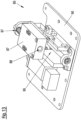
- a fitting system 17 which is formed by a set of modular functional units 19.
- two modular storage units 21a, 21b serve to mount the sash 15 on a hinge side 22 of the window 11 on the frame 13 so that it can rotate about an axis of rotation D.
- an opener/closer unit 25 On the opposite hinge side 23 of the window 11 there is an opener/closer unit 25 for automatically opening and closing the sash 15 during an automatic phase.
- the set of modular functional units 19 in the illustrated embodiment includes three closure units 27 for releasably fixing the sash 15 to the frame 13.
- closure units 27 are on different sides of the window 11 arranged. It goes without saying that additional locking units 27 can be provided to improve burglary protection and that in certain applications a single locking unit 27 can be sufficient. All modular functional units 19 are arranged concealed and are not visible when the wing 15 is closed.
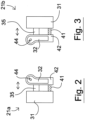
- the bearing unit 21a has a first bearing part 31 designed for direct or indirect attachment to the frame 13 and a second bearing part 32 designed for direct or indirect attachment to the wing 15.
- the second bearing part 32 is rotatably mounted on a displacement body 42 by means of a pivot bearing 44.
- the displacement body 42 is attached to a guide rail 35, which is slidably mounted on the first bearing part 31.
- a spindle drive 41 By means of a spindle drive 41, the displacement body 42 and with it the second bearing part 32 can be offset relative to the first bearing part 31 by an offset of approximately 60 mm, starting from a basic state in which the first bearing part 31 and the displacement body 42 adjoin one another.
- the displacement takes place transversely to the frame level.
- a drive (not shown) connected to the spindle drive 41, the second bearing part 32 can be put into a switched off state and back into the basic state.
- Fig. 3 shows the upper storage unit 21b in an individual view. It is designed symmetrically to the lower storage unit 21a. If with the in Fig. 1 Window 11 shown, the hinge side should be on the left side in the picture, this can also be done in Figs. 2 and 3 shown pair of upper bearing unit 21a and lower bearing unit 21b can be used.
- the storage units 21a, 21b simply have to be installed interchangeably, i.e. the lower storage unit 21a at the top and the upper storage unit 21b at the bottom.
- the locking unit 27 shown individually has a housing 45 in which an invisible drive, comprising an electric motor and a gear, is housed. By means of the drive, a locking pin 47 can be moved between a fixing position and a release position according to an arrow 48.
- the housing 45 is designed to be attached to the frame 13. In the assembled state of the closure unit 27, the direction of displacement is parallel to the frame plane.
- the locking pin 47 has a circumferential groove 49 at its free end.
- the closure unit 27 is assigned a, for example bush-like, holding receptacle 55 arranged on the wing 15 and a securing arm 57 which is pivotably mounted on the wing 15.
- An elongated recess 59 is formed in the securing arm 57, which has an extension 60 at one end.
- the locking pin 47 When the locking pin 47 is in a retracted release position, it neither engages in the holding receptacle 55 nor in the recess 59 of the securing arm 57 and the locking unit 27 is inactive. When the locking pin 47 is in a fully extended fixing position, it engages in the holding receptacle 55 and thus fixes the sash 15 on the frame 13. In a securing position located between the release position and the fixing position, the locking pin 47 engages in the extension 60 of the recess 59 but not yet into the holding receptacle 55.
- the locking pin 47 takes the securing arm 57 with it and pivots it, with the groove 49 in a positive engagement with the tapered section of the recess 59 reached. As soon as the locking pin 47 has reached the end of the recess 59, further movement of the sash 15 away from the frame 13 is blocked and the sash 15 is secured. This condition is in Fig. 5 shown. The locking pin 47 can only be retracted when the wing 15 is closed.
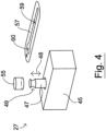
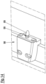
- Individually shown opener/closer unit 25 not according to the invention comprises a housing 65 which is designed for attachment to the frame 13.
- a housing 65 which is designed for attachment to the frame 13.
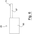
- an invisible drive by means of which an actuating element 67 can be extended out of the housing 65 and retracted into it.
- a snapper 71 is movably mounted at the free end of the adjusting element 67. The snapper 71 can engage behind a counter element, not shown, of the wing 15 in a generally known manner and thus releasably couple it to the wing 15.
- the wing 15 When the actuating element 67 is retracted, the wing 15 can be opened and closed automatically during an automatic phase.
- the snapper 71 enables the actuating element 67 to be automatically coupled out and engaged in a manner similar to that of a drawer retractor.
- Fig. 7 shows the wing 15 in a closed position.
- the second bearing parts 32 of the bearing units 21a, 21b are in an unstaggered initial state, the locking pins 47 of all locking units 27 are in a fully extended fixing position and the actuating element 67 of the opener/closer unit 25 is completely retracted.
- Fig. 8 shows the wing 15 in a simply tilted state.
- the second bearing part 32 of the upper bearing unit 21b is maximally offset, while the second bearing part 32 of the lower bearing unit 21a is in the unstaggered initial state.
- the locking pin 47 of the lower locking unit 27 is in the fully extended fixing position and serves as a tilt bearing, while the locking pins 47 of the remaining two locking units 27 are in the retracted release position.
- the control element 67 of the opener/closer unit 25 is decoupled from the wing 15.
- “inverted tilting” is also possible, in which the second bearing part 32 of the lower bearing unit 21a is maximally offset, while the second bearing part 32 of the upper bearing unit 21b is in the unstaggered initial state.
- the locking pin 47 of the upper locking unit 27 is then in the fully extended position and serves as an upper tilt bearing, while the locking pins 47 of the remaining two locking units 27 are in the retracted release position.
- Fig. 9 shows the wing 15 in a tilted and secured state. This condition largely corresponds to that in Fig. 8 State shown, apart from the fact that the locking pins 47 of the upper and side locking units 27 are in the half-extended securing position and therefore have taken the securing arms 57 with them when tilting. This makes it more difficult to open the wing 15 by force. Here too, a secured “inverted tilt position” is possible again.
- Fig. 10 shows the wing 15 in a simply parked state. This state can be created as an alternative to the tilted state for ventilation.
- the sash plane is spaced from the frame plane and runs parallel to it.
- the second bearing parts 32 of both bearing units 21a, 21b are maximally offset.
- the actuating element 67 of the opener/closer unit 25 is extended as far as it corresponds to the offset of the bearing units 21a, 21b.
- the locking pins 47 of all locking units 27 are retracted.
- Fig. 11 shows the wing 15 in a parked and secured state. This condition largely corresponds to that in Fig. 10 shown state, apart from the fact that the locking pins 47 of all locking units 27 are in the half-extended securing position and therefore have taken the securing arms 57 with them when tilted. This makes it more difficult to open the wing 15 by force.
- Fig. 12 shows the wing 15 in an open state.
- the second bearing parts 32 of both bearing units 21a, 21b are maximally offset.
- the control element 67 of the opener/closer unit 25 is extended and decoupled from the wing 15.
- the locking pins 47 of all locking units 27 are retracted. While closing of the sash 15, the actuating element 67 couples to the sash edge in good time before the sash 15 hits the frame 13 and takes over the further, damped closing.
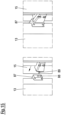
- FIG. 13 to 15 an embodiment of an opener/closer unit 85 according to the invention is shown.
- the actuating element 87 of this opener/closer unit 85 is a block-shaped slide which is mounted on a base body 90 so that it can be moved by means of a linear guide 95.
- the base body 90 is designed for attachment to the frame 13.
- a pin receptacle 88 is formed on a front side of the adjusting element 87.
- the back of the adjusting element 87 is supported on the base body 90 in a damped manner by means of a spring 97.
- the opener/closer unit 85 works with an in Fig. 14 shown counter element 98 together, which can be attached to the wing 15 and has a locking pin 89 with a circumferential groove 99.
- the opener/closer unit 85 and the counter element 98 are to be attached to the frame 13 and the sash 15 in such a way that the locking pin 89 reaches the pin receptacle 88 when the sash 15 is closed, as shown in Fig. 15 is shown.
- a magnetic release device ensures that a movable locking element (in Fig. 13-15 not recognizable) reaches a locking position in which it positively fits into the groove 99 of the locking pin 89 intervenes.
- the wing 15 is then secured to the frame 13 with a high holding force, but is still in a position spaced from the frame 13, as in the right part of Fig. 15 shown can be located.
- the triggering device can activate the drive of the opener/closer unit 85 and thus ensure a displacement of the actuating element 87 relative to the base body 90 in the sense that the wing 15 is completely pulled towards the frame 13.
- a "throw" of the wing 15 by a user is dampened by the spring 97.
- the opener/closer unit 85 is also preferably designed in such a way that the wing 15 can be opened in the “tip-on” mode.
Landscapes
- Engineering & Computer Science (AREA)
- Mechanical Engineering (AREA)
- Structural Engineering (AREA)
- Physics & Mathematics (AREA)
- Electromagnetism (AREA)
- Power-Operated Mechanisms For Wings (AREA)
Applications Claiming Priority (2)
| Application Number | Priority Date | Filing Date | Title |
|---|---|---|---|
| DE102017104405.1A DE102017104405A1 (de) | 2017-03-02 | 2017-03-02 | Beschlagsystem |
| PCT/EP2018/055062 WO2018158376A1 (de) | 2017-03-02 | 2018-03-01 | Beschlagsystem |
Publications (2)
| Publication Number | Publication Date |
|---|---|
| EP3580411A1 EP3580411A1 (de) | 2019-12-18 |
| EP3580411B1 true EP3580411B1 (de) | 2024-01-24 |
Family
ID=61627068
Family Applications (1)
| Application Number | Title | Priority Date | Filing Date |
|---|---|---|---|
| EP18710802.2A Active EP3580411B1 (de) | 2017-03-02 | 2018-03-01 | Beschlagsystem |
Country Status (4)
| Country | Link |
|---|---|
| EP (1) | EP3580411B1 (pl) |
| DE (1) | DE102017104405A1 (pl) |
| PL (1) | PL3580411T3 (pl) |
| WO (1) | WO2018158376A1 (pl) |
Families Citing this family (7)
| Publication number | Priority date | Publication date | Assignee | Title |
|---|---|---|---|---|
| DE102018217171A1 (de) * | 2018-10-08 | 2020-04-09 | Aug. Winkhaus Gmbh & Co. Kg | Treibstangenbeschlag für einen gegen einen Rahmen schwenkbaren Flügel eines Fensters |
| CN110541621A (zh) * | 2019-08-28 | 2019-12-06 | 合肥四周建筑装饰有限公司 | 一种多重锁定的防盗型平开窗 |
| DE102019126117A1 (de) | 2019-09-27 | 2021-04-01 | Maco Technologie Gmbh | Beschlagsystem und Bauelement |
| DE102020210166A1 (de) | 2020-08-11 | 2022-02-17 | Robert Bosch Gesellschaft mit beschränkter Haftung | Vorrichtung zur Überwachung eines Objekts, insbesondere eines Fensters oder einer Tür eines Gebäudes oder eines Solarmoduls, sowie ein Objekt mit einer solchen Vorrichtung |
| DE102020122854A1 (de) | 2020-09-01 | 2022-03-03 | Maco Technologie Gmbh | Beschlaganordnung |
| DE102020122859A1 (de) | 2020-09-01 | 2022-03-03 | Maco Technologie Gmbh | Fenster |
| CN114293880B (zh) * | 2021-12-30 | 2023-04-07 | 极景门窗有限公司 | 一种单元化隐藏式五金及型材 |
Family Cites Families (12)
| Publication number | Priority date | Publication date | Assignee | Title |
|---|---|---|---|---|
| DE3844101A1 (de) | 1988-12-28 | 1990-07-05 | Ludwig Kessler | Elektromechanische vorrichtung zum schliessen und oeffnen von fenstern |
| US5016931A (en) * | 1989-06-20 | 1991-05-21 | The Hartwell Corporation | Latching mechanism having a pre-adjusted load |
| US5896763A (en) * | 1995-06-22 | 1999-04-27 | Winkhaus Gmbh & Co. Kg | Locking device with a leaf-restraining device |
| DE19603768A1 (de) * | 1996-02-02 | 1997-08-07 | Winkhaus Fa August | Fenster, Tür oder dergleichen, gegebenenfalls mit Schwenkantrieb |
| DE19741728C2 (de) | 1997-09-22 | 2001-05-03 | Esco Metallbaubeschlag Handel Gmbh | Ausstellmechanismus |
| GB9930304D0 (en) * | 1999-12-22 | 2000-02-09 | Mila Hardware Ltd | Lock mechanism |
| DK174562B1 (da) | 2000-11-15 | 2003-06-10 | Vkr Holding As | Vindueskonstruktion med flere åbningsmåder |
| DE10226325C1 (de) | 2002-06-11 | 2003-07-17 | Ingo Bruchhold | Fenster für Lüftungssystem |
| DE102009035737A1 (de) * | 2009-08-01 | 2011-02-03 | Assa Abloy Sicherheitstechnik Gmbh | Zuziehvorrichtung für eine Tür |
| DE102012203602A1 (de) * | 2012-03-07 | 2013-09-12 | Brose Fahrzeugteile Gmbh & Co. Kommanditgesellschaft, Coburg | Baugruppe eines Fensters oder einer Tür für ein Gebäude |
| DE102014202362B4 (de) * | 2014-02-10 | 2018-12-13 | Kendrion Kuhnke Automation Gmbh | Motorisch angetriebene Verschlusseinrichtung, Heißgerät und Verfahren zum Betrieb einer motorischen Verschlusseinrichtung |
| WO2016168538A1 (en) * | 2015-04-16 | 2016-10-20 | Southco, Inc. | Electromechanical compression latch and latching system |
-
2017
- 2017-03-02 DE DE102017104405.1A patent/DE102017104405A1/de not_active Withdrawn
-
2018
- 2018-03-01 EP EP18710802.2A patent/EP3580411B1/de active Active
- 2018-03-01 WO PCT/EP2018/055062 patent/WO2018158376A1/de not_active Ceased
- 2018-03-01 PL PL18710802.2T patent/PL3580411T3/pl unknown
Also Published As
| Publication number | Publication date |
|---|---|
| EP3580411A1 (de) | 2019-12-18 |
| WO2018158376A1 (de) | 2018-09-07 |
| PL3580411T3 (pl) | 2024-06-24 |
| DE102017104405A1 (de) | 2018-09-06 |
Similar Documents
| Publication | Publication Date | Title |
|---|---|---|
| EP3580411B1 (de) | Beschlagsystem | |
| EP2475834B1 (de) | Durchgangssperre | |
| EP3073040B1 (de) | Feststeller zum arretieren eines kipp- und/oder schwenkbaren fensterflügels | |
| EP2594713B1 (de) | Türöffner | |
| EP2430273B1 (de) | Aufschwenkbarer möbelklappenantrieb | |
| EP1837470B1 (de) | Fenster- oder Türelement mit einem automatischen Antrieb | |
| EP1921233B1 (de) | Nachrüstbarer Betätigungsantrieb für ein Schwenktor o.dgl. | |
| EP1580369B1 (de) | Antriebseinrichtung | |
| DE102014119734B4 (de) | Verfahren zum Betreiben eines Türantriebs, Türantriebssteuerung, Türantrieb und Drehflügeltür | |
| WO2018206307A1 (de) | Fenster oder tür mit einbruchsicherer kippöffnungsbegrenzung | |
| WO1997028339A1 (de) | Fenster, tür oder dergleichen, gegebenenfalls mit schwenkantrieb | |
| EP1740792B1 (de) | Drehkippfenster | |
| EP1865130B1 (de) | Entriegelungsanordnung eines Fensters, einer Tür oder dergleichen | |
| DE10290395B4 (de) | Verschluss-System | |
| EP4448896B1 (de) | Verriegelungsvorrichtung für eine tür | |
| EP3921499A1 (de) | Kippantriebsvorrichtung für einen flügel | |
| EP3237708B1 (de) | Beschlag zum einbau zwischen einem flügel und einem festen rahmen eines fensters, einer tür oder dergleichen sowie fenster, tür oder dergleichen mit einem derartigen beschlag | |
| EP3245372B1 (de) | Verfahren zum betreiben eines türantriebs, türantriebssteuerung, türantrieb und drehflügeltür | |
| EP3740638B1 (de) | Funktionseinheit | |
| EP3219887A1 (de) | Universelle anti-panikdruckstange | |
| EP3334877B1 (de) | Verriegelungsvorrichtung für schiebeflügel | |
| EP1218613B1 (de) | Einrichtung zum verschliessen oder freigeben einer öffnung | |
| DE112010000461B4 (de) | Einrichtung zum automatischen Öffnen und Schließen sowie Verriegeln und Entriegeln von Toren | |
| DE19723174C2 (de) | Elektrisch betriebener Sicherheitsverschluß mit zusätzlichem Betätigungsantrieb für Türen und Fenster | |
| DE29614557U1 (de) | Dreh-Kippfenster oder -Tür |
Legal Events
| Date | Code | Title | Description |
|---|---|---|---|
| STAA | Information on the status of an ep patent application or granted ep patent |
Free format text: STATUS: UNKNOWN |
|
| STAA | Information on the status of an ep patent application or granted ep patent |
Free format text: STATUS: THE INTERNATIONAL PUBLICATION HAS BEEN MADE |
|
| PUAI | Public reference made under article 153(3) epc to a published international application that has entered the european phase |
Free format text: ORIGINAL CODE: 0009012 |
|
| STAA | Information on the status of an ep patent application or granted ep patent |
Free format text: STATUS: REQUEST FOR EXAMINATION WAS MADE |
|
| 17P | Request for examination filed |
Effective date: 20190913 |
|
| AK | Designated contracting states |
Kind code of ref document: A1 Designated state(s): AL AT BE BG CH CY CZ DE DK EE ES FI FR GB GR HR HU IE IS IT LI LT LU LV MC MK MT NL NO PL PT RO RS SE SI SK SM TR |
|
| AX | Request for extension of the european patent |
Extension state: BA ME |
|
| RIN1 | Information on inventor provided before grant (corrected) |
Inventor name: BRUNAUER, GEORG Inventor name: STEINDL, CHRISTIAN Inventor name: DUCHAC, ROBIN Inventor name: HAGER, HANS Inventor name: RIEGER, WOLFGANG |
|
| DAV | Request for validation of the european patent (deleted) | ||
| DAX | Request for extension of the european patent (deleted) | ||
| GRAP | Despatch of communication of intention to grant a patent |
Free format text: ORIGINAL CODE: EPIDOSNIGR1 |
|
| STAA | Information on the status of an ep patent application or granted ep patent |
Free format text: STATUS: GRANT OF PATENT IS INTENDED |
|
| INTG | Intention to grant announced |
Effective date: 20230927 |
|
| GRAS | Grant fee paid |
Free format text: ORIGINAL CODE: EPIDOSNIGR3 |
|
| P01 | Opt-out of the competence of the unified patent court (upc) registered |
Effective date: 20231106 |
|
| GRAA | (expected) grant |
Free format text: ORIGINAL CODE: 0009210 |
|
| STAA | Information on the status of an ep patent application or granted ep patent |
Free format text: STATUS: THE PATENT HAS BEEN GRANTED |
|
| AK | Designated contracting states |
Kind code of ref document: B1 Designated state(s): AL AT BE BG CH CY CZ DE DK EE ES FI FR GB GR HR HU IE IS IT LI LT LU LV MC MK MT NL NO PL PT RO RS SE SI SK SM TR |
|
| REG | Reference to a national code |
Ref country code: GB Ref legal event code: FG4D Free format text: NOT ENGLISH |
|
| REG | Reference to a national code |
Ref country code: CH Ref legal event code: EP |
|
| REG | Reference to a national code |
Ref country code: IE Ref legal event code: FG4D Free format text: LANGUAGE OF EP DOCUMENT: GERMAN |
|
| REG | Reference to a national code |
Ref country code: DE Ref legal event code: R096 Ref document number: 502018014027 Country of ref document: DE |
|
| REG | Reference to a national code |
Ref country code: LT Ref legal event code: MG9D |
|
| REG | Reference to a national code |
Ref country code: NL Ref legal event code: MP Effective date: 20240124 |
|
| PG25 | Lapsed in a contracting state [announced via postgrant information from national office to epo] |
Ref country code: NL Free format text: LAPSE BECAUSE OF FAILURE TO SUBMIT A TRANSLATION OF THE DESCRIPTION OR TO PAY THE FEE WITHIN THE PRESCRIBED TIME-LIMIT Effective date: 20240124 |
|
| PG25 | Lapsed in a contracting state [announced via postgrant information from national office to epo] |
Ref country code: NL Free format text: LAPSE BECAUSE OF FAILURE TO SUBMIT A TRANSLATION OF THE DESCRIPTION OR TO PAY THE FEE WITHIN THE PRESCRIBED TIME-LIMIT Effective date: 20240124 |
|
| PG25 | Lapsed in a contracting state [announced via postgrant information from national office to epo] |
Ref country code: IS Free format text: LAPSE BECAUSE OF FAILURE TO SUBMIT A TRANSLATION OF THE DESCRIPTION OR TO PAY THE FEE WITHIN THE PRESCRIBED TIME-LIMIT Effective date: 20240524 |
|
| PG25 | Lapsed in a contracting state [announced via postgrant information from national office to epo] |
Ref country code: LT Free format text: LAPSE BECAUSE OF FAILURE TO SUBMIT A TRANSLATION OF THE DESCRIPTION OR TO PAY THE FEE WITHIN THE PRESCRIBED TIME-LIMIT Effective date: 20240124 |
|
| PG25 | Lapsed in a contracting state [announced via postgrant information from national office to epo] |
Ref country code: GR Free format text: LAPSE BECAUSE OF FAILURE TO SUBMIT A TRANSLATION OF THE DESCRIPTION OR TO PAY THE FEE WITHIN THE PRESCRIBED TIME-LIMIT Effective date: 20240425 |
|
| PG25 | Lapsed in a contracting state [announced via postgrant information from national office to epo] |
Ref country code: RS Free format text: LAPSE BECAUSE OF FAILURE TO SUBMIT A TRANSLATION OF THE DESCRIPTION OR TO PAY THE FEE WITHIN THE PRESCRIBED TIME-LIMIT Effective date: 20240424 Ref country code: HR Free format text: LAPSE BECAUSE OF FAILURE TO SUBMIT A TRANSLATION OF THE DESCRIPTION OR TO PAY THE FEE WITHIN THE PRESCRIBED TIME-LIMIT Effective date: 20240124 |
|
| PG25 | Lapsed in a contracting state [announced via postgrant information from national office to epo] |
Ref country code: ES Free format text: LAPSE BECAUSE OF FAILURE TO SUBMIT A TRANSLATION OF THE DESCRIPTION OR TO PAY THE FEE WITHIN THE PRESCRIBED TIME-LIMIT Effective date: 20240124 |
|
| PG25 | Lapsed in a contracting state [announced via postgrant information from national office to epo] |
Ref country code: RS Free format text: LAPSE BECAUSE OF FAILURE TO SUBMIT A TRANSLATION OF THE DESCRIPTION OR TO PAY THE FEE WITHIN THE PRESCRIBED TIME-LIMIT Effective date: 20240424 Ref country code: NO Free format text: LAPSE BECAUSE OF FAILURE TO SUBMIT A TRANSLATION OF THE DESCRIPTION OR TO PAY THE FEE WITHIN THE PRESCRIBED TIME-LIMIT Effective date: 20240424 Ref country code: LT Free format text: LAPSE BECAUSE OF FAILURE TO SUBMIT A TRANSLATION OF THE DESCRIPTION OR TO PAY THE FEE WITHIN THE PRESCRIBED TIME-LIMIT Effective date: 20240124 Ref country code: IS Free format text: LAPSE BECAUSE OF FAILURE TO SUBMIT A TRANSLATION OF THE DESCRIPTION OR TO PAY THE FEE WITHIN THE PRESCRIBED TIME-LIMIT Effective date: 20240524 Ref country code: HR Free format text: LAPSE BECAUSE OF FAILURE TO SUBMIT A TRANSLATION OF THE DESCRIPTION OR TO PAY THE FEE WITHIN THE PRESCRIBED TIME-LIMIT Effective date: 20240124 Ref country code: GR Free format text: LAPSE BECAUSE OF FAILURE TO SUBMIT A TRANSLATION OF THE DESCRIPTION OR TO PAY THE FEE WITHIN THE PRESCRIBED TIME-LIMIT Effective date: 20240425 Ref country code: FI Free format text: LAPSE BECAUSE OF FAILURE TO SUBMIT A TRANSLATION OF THE DESCRIPTION OR TO PAY THE FEE WITHIN THE PRESCRIBED TIME-LIMIT Effective date: 20240124 Ref country code: ES Free format text: LAPSE BECAUSE OF FAILURE TO SUBMIT A TRANSLATION OF THE DESCRIPTION OR TO PAY THE FEE WITHIN THE PRESCRIBED TIME-LIMIT Effective date: 20240124 Ref country code: BG Free format text: LAPSE BECAUSE OF FAILURE TO SUBMIT A TRANSLATION OF THE DESCRIPTION OR TO PAY THE FEE WITHIN THE PRESCRIBED TIME-LIMIT Effective date: 20240124 |
|
| PG25 | Lapsed in a contracting state [announced via postgrant information from national office to epo] |
Ref country code: PT Free format text: LAPSE BECAUSE OF FAILURE TO SUBMIT A TRANSLATION OF THE DESCRIPTION OR TO PAY THE FEE WITHIN THE PRESCRIBED TIME-LIMIT Effective date: 20240524 |
|
| PG25 | Lapsed in a contracting state [announced via postgrant information from national office to epo] |
Ref country code: SE Free format text: LAPSE BECAUSE OF FAILURE TO SUBMIT A TRANSLATION OF THE DESCRIPTION OR TO PAY THE FEE WITHIN THE PRESCRIBED TIME-LIMIT Effective date: 20240124 Ref country code: PT Free format text: LAPSE BECAUSE OF FAILURE TO SUBMIT A TRANSLATION OF THE DESCRIPTION OR TO PAY THE FEE WITHIN THE PRESCRIBED TIME-LIMIT Effective date: 20240524 Ref country code: LV Free format text: LAPSE BECAUSE OF FAILURE TO SUBMIT A TRANSLATION OF THE DESCRIPTION OR TO PAY THE FEE WITHIN THE PRESCRIBED TIME-LIMIT Effective date: 20240124 |
|
| PG25 | Lapsed in a contracting state [announced via postgrant information from national office to epo] |
Ref country code: DK Free format text: LAPSE BECAUSE OF FAILURE TO SUBMIT A TRANSLATION OF THE DESCRIPTION OR TO PAY THE FEE WITHIN THE PRESCRIBED TIME-LIMIT Effective date: 20240124 |
|
| PG25 | Lapsed in a contracting state [announced via postgrant information from national office to epo] |
Ref country code: SM Free format text: LAPSE BECAUSE OF FAILURE TO SUBMIT A TRANSLATION OF THE DESCRIPTION OR TO PAY THE FEE WITHIN THE PRESCRIBED TIME-LIMIT Effective date: 20240124 |
|
| PG25 | Lapsed in a contracting state [announced via postgrant information from national office to epo] |
Ref country code: EE Free format text: LAPSE BECAUSE OF FAILURE TO SUBMIT A TRANSLATION OF THE DESCRIPTION OR TO PAY THE FEE WITHIN THE PRESCRIBED TIME-LIMIT Effective date: 20240124 Ref country code: CZ Free format text: LAPSE BECAUSE OF FAILURE TO SUBMIT A TRANSLATION OF THE DESCRIPTION OR TO PAY THE FEE WITHIN THE PRESCRIBED TIME-LIMIT Effective date: 20240124 |
|
| REG | Reference to a national code |
Ref country code: DE Ref legal event code: R097 Ref document number: 502018014027 Country of ref document: DE |
|
| PG25 | Lapsed in a contracting state [announced via postgrant information from national office to epo] |
Ref country code: SK Free format text: LAPSE BECAUSE OF FAILURE TO SUBMIT A TRANSLATION OF THE DESCRIPTION OR TO PAY THE FEE WITHIN THE PRESCRIBED TIME-LIMIT Effective date: 20240124 |
|
| PG25 | Lapsed in a contracting state [announced via postgrant information from national office to epo] |
Ref country code: SM Free format text: LAPSE BECAUSE OF FAILURE TO SUBMIT A TRANSLATION OF THE DESCRIPTION OR TO PAY THE FEE WITHIN THE PRESCRIBED TIME-LIMIT Effective date: 20240124 Ref country code: SK Free format text: LAPSE BECAUSE OF FAILURE TO SUBMIT A TRANSLATION OF THE DESCRIPTION OR TO PAY THE FEE WITHIN THE PRESCRIBED TIME-LIMIT Effective date: 20240124 Ref country code: RO Free format text: LAPSE BECAUSE OF FAILURE TO SUBMIT A TRANSLATION OF THE DESCRIPTION OR TO PAY THE FEE WITHIN THE PRESCRIBED TIME-LIMIT Effective date: 20240124 Ref country code: EE Free format text: LAPSE BECAUSE OF FAILURE TO SUBMIT A TRANSLATION OF THE DESCRIPTION OR TO PAY THE FEE WITHIN THE PRESCRIBED TIME-LIMIT Effective date: 20240124 Ref country code: DK Free format text: LAPSE BECAUSE OF FAILURE TO SUBMIT A TRANSLATION OF THE DESCRIPTION OR TO PAY THE FEE WITHIN THE PRESCRIBED TIME-LIMIT Effective date: 20240124 Ref country code: CZ Free format text: LAPSE BECAUSE OF FAILURE TO SUBMIT A TRANSLATION OF THE DESCRIPTION OR TO PAY THE FEE WITHIN THE PRESCRIBED TIME-LIMIT Effective date: 20240124 |
|
| REG | Reference to a national code |
Ref country code: CH Ref legal event code: PL |
|
| PG25 | Lapsed in a contracting state [announced via postgrant information from national office to epo] |
Ref country code: LU Free format text: LAPSE BECAUSE OF NON-PAYMENT OF DUE FEES Effective date: 20240301 |
|
| PG25 | Lapsed in a contracting state [announced via postgrant information from national office to epo] |
Ref country code: MC Free format text: LAPSE BECAUSE OF FAILURE TO SUBMIT A TRANSLATION OF THE DESCRIPTION OR TO PAY THE FEE WITHIN THE PRESCRIBED TIME-LIMIT Effective date: 20240124 |
|
| PG25 | Lapsed in a contracting state [announced via postgrant information from national office to epo] |
Ref country code: MC Free format text: LAPSE BECAUSE OF FAILURE TO SUBMIT A TRANSLATION OF THE DESCRIPTION OR TO PAY THE FEE WITHIN THE PRESCRIBED TIME-LIMIT Effective date: 20240124 Ref country code: LU Free format text: LAPSE BECAUSE OF NON-PAYMENT OF DUE FEES Effective date: 20240301 |
|
| PLBE | No opposition filed within time limit |
Free format text: ORIGINAL CODE: 0009261 |
|
| STAA | Information on the status of an ep patent application or granted ep patent |
Free format text: STATUS: NO OPPOSITION FILED WITHIN TIME LIMIT |
|
| REG | Reference to a national code |
Ref country code: BE Ref legal event code: MM Effective date: 20240331 |
|
| 26N | No opposition filed |
Effective date: 20241025 |
|
| PG25 | Lapsed in a contracting state [announced via postgrant information from national office to epo] |
Ref country code: BE Free format text: LAPSE BECAUSE OF NON-PAYMENT OF DUE FEES Effective date: 20240331 |
|
| PG25 | Lapsed in a contracting state [announced via postgrant information from national office to epo] |
Ref country code: IE Free format text: LAPSE BECAUSE OF NON-PAYMENT OF DUE FEES Effective date: 20240301 |
|
| PG25 | Lapsed in a contracting state [announced via postgrant information from national office to epo] |
Ref country code: IE Free format text: LAPSE BECAUSE OF NON-PAYMENT OF DUE FEES Effective date: 20240301 Ref country code: BE Free format text: LAPSE BECAUSE OF NON-PAYMENT OF DUE FEES Effective date: 20240331 Ref country code: CH Free format text: LAPSE BECAUSE OF NON-PAYMENT OF DUE FEES Effective date: 20240331 |
|
| PGFP | Annual fee paid to national office [announced via postgrant information from national office to epo] |
Ref country code: DE Payment date: 20250319 Year of fee payment: 8 |
|
| PG25 | Lapsed in a contracting state [announced via postgrant information from national office to epo] |
Ref country code: SI Free format text: LAPSE BECAUSE OF FAILURE TO SUBMIT A TRANSLATION OF THE DESCRIPTION OR TO PAY THE FEE WITHIN THE PRESCRIBED TIME-LIMIT Effective date: 20240124 |
|
| PGFP | Annual fee paid to national office [announced via postgrant information from national office to epo] |
Ref country code: AT Payment date: 20250320 Year of fee payment: 8 |
|
| PGFP | Annual fee paid to national office [announced via postgrant information from national office to epo] |
Ref country code: FR Payment date: 20250326 Year of fee payment: 8 Ref country code: PL Payment date: 20250221 Year of fee payment: 8 |
|
| PGFP | Annual fee paid to national office [announced via postgrant information from national office to epo] |
Ref country code: IT Payment date: 20250325 Year of fee payment: 8 Ref country code: GB Payment date: 20250324 Year of fee payment: 8 |
|
| PG25 | Lapsed in a contracting state [announced via postgrant information from national office to epo] |
Ref country code: CY Free format text: LAPSE BECAUSE OF FAILURE TO SUBMIT A TRANSLATION OF THE DESCRIPTION OR TO PAY THE FEE WITHIN THE PRESCRIBED TIME-LIMIT; INVALID AB INITIO Effective date: 20180301 |
|
| PG25 | Lapsed in a contracting state [announced via postgrant information from national office to epo] |
Ref country code: HU Free format text: LAPSE BECAUSE OF FAILURE TO SUBMIT A TRANSLATION OF THE DESCRIPTION OR TO PAY THE FEE WITHIN THE PRESCRIBED TIME-LIMIT; INVALID AB INITIO Effective date: 20180301 |
|
| PG25 | Lapsed in a contracting state [announced via postgrant information from national office to epo] |
Ref country code: TR Free format text: LAPSE BECAUSE OF FAILURE TO SUBMIT A TRANSLATION OF THE DESCRIPTION OR TO PAY THE FEE WITHIN THE PRESCRIBED TIME-LIMIT Effective date: 20240124 |