EP3579217B1 - Produkt mit eingebauter betriebsanzeigetafel - Google Patents
Produkt mit eingebauter betriebsanzeigetafel Download PDFInfo
- Publication number
- EP3579217B1 EP3579217B1 EP18870982.8A EP18870982A EP3579217B1 EP 3579217 B1 EP3579217 B1 EP 3579217B1 EP 18870982 A EP18870982 A EP 18870982A EP 3579217 B1 EP3579217 B1 EP 3579217B1
- Authority
- EP
- European Patent Office
- Prior art keywords
- display panel
- operation display
- light emitting
- panel
- emitting element
- Prior art date
- Legal status (The legal status is an assumption and is not a legal conclusion. Google has not performed a legal analysis and makes no representation as to the accuracy of the status listed.)
- Active
Links
Images


Classifications
-
- G—PHYSICS
- G09—EDUCATION; CRYPTOGRAPHY; DISPLAY; ADVERTISING; SEALS
- G09F—DISPLAYING; ADVERTISING; SIGNS; LABELS OR NAME-PLATES; SEALS
- G09F23/00—Advertising on or in specific articles, e.g. ashtrays, letter-boxes
-
- B—PERFORMING OPERATIONS; TRANSPORTING
- B60—VEHICLES IN GENERAL
- B60K—ARRANGEMENT OR MOUNTING OF PROPULSION UNITS OR OF TRANSMISSIONS IN VEHICLES; ARRANGEMENT OR MOUNTING OF PLURAL DIVERSE PRIME-MOVERS IN VEHICLES; AUXILIARY DRIVES FOR VEHICLES; INSTRUMENTATION OR DASHBOARDS FOR VEHICLES; ARRANGEMENTS IN CONNECTION WITH COOLING, AIR INTAKE, GAS EXHAUST OR FUEL SUPPLY OF PROPULSION UNITS IN VEHICLES
- B60K35/00—Instruments specially adapted for vehicles; Arrangement of instruments in or on vehicles
- B60K35/10—Input arrangements, i.e. from user to vehicle, associated with vehicle functions or specially adapted therefor
-
- B—PERFORMING OPERATIONS; TRANSPORTING
- B60—VEHICLES IN GENERAL
- B60K—ARRANGEMENT OR MOUNTING OF PROPULSION UNITS OR OF TRANSMISSIONS IN VEHICLES; ARRANGEMENT OR MOUNTING OF PLURAL DIVERSE PRIME-MOVERS IN VEHICLES; AUXILIARY DRIVES FOR VEHICLES; INSTRUMENTATION OR DASHBOARDS FOR VEHICLES; ARRANGEMENTS IN CONNECTION WITH COOLING, AIR INTAKE, GAS EXHAUST OR FUEL SUPPLY OF PROPULSION UNITS IN VEHICLES
- B60K35/00—Instruments specially adapted for vehicles; Arrangement of instruments in or on vehicles
- B60K35/20—Output arrangements, i.e. from vehicle to user, associated with vehicle functions or specially adapted therefor
- B60K35/21—Output arrangements, i.e. from vehicle to user, associated with vehicle functions or specially adapted therefor using visual output, e.g. blinking lights or matrix displays
- B60K35/22—Display screens
-
- B—PERFORMING OPERATIONS; TRANSPORTING
- B60—VEHICLES IN GENERAL
- B60K—ARRANGEMENT OR MOUNTING OF PROPULSION UNITS OR OF TRANSMISSIONS IN VEHICLES; ARRANGEMENT OR MOUNTING OF PLURAL DIVERSE PRIME-MOVERS IN VEHICLES; AUXILIARY DRIVES FOR VEHICLES; INSTRUMENTATION OR DASHBOARDS FOR VEHICLES; ARRANGEMENTS IN CONNECTION WITH COOLING, AIR INTAKE, GAS EXHAUST OR FUEL SUPPLY OF PROPULSION UNITS IN VEHICLES
- B60K35/00—Instruments specially adapted for vehicles; Arrangement of instruments in or on vehicles
- B60K35/60—Instruments characterised by their location or relative disposition in or on vehicles
-
- G—PHYSICS
- G02—OPTICS
- G02B—OPTICAL ELEMENTS, SYSTEMS OR APPARATUS
- G02B6/00—Light guides; Structural details of arrangements comprising light guides and other optical elements, e.g. couplings
- G02B6/0001—Light guides; Structural details of arrangements comprising light guides and other optical elements, e.g. couplings specially adapted for lighting devices or systems
- G02B6/0011—Light guides; Structural details of arrangements comprising light guides and other optical elements, e.g. couplings specially adapted for lighting devices or systems the light guides being planar or of plate-like form
- G02B6/0066—Light guides; Structural details of arrangements comprising light guides and other optical elements, e.g. couplings specially adapted for lighting devices or systems the light guides being planar or of plate-like form characterised by the light source being coupled to the light guide
- G02B6/0068—Arrangements of plural sources, e.g. multi-colour light sources
-
- G—PHYSICS
- G02—OPTICS
- G02B—OPTICAL ELEMENTS, SYSTEMS OR APPARATUS
- G02B6/00—Light guides; Structural details of arrangements comprising light guides and other optical elements, e.g. couplings
- G02B6/0001—Light guides; Structural details of arrangements comprising light guides and other optical elements, e.g. couplings specially adapted for lighting devices or systems
- G02B6/0011—Light guides; Structural details of arrangements comprising light guides and other optical elements, e.g. couplings specially adapted for lighting devices or systems the light guides being planar or of plate-like form
- G02B6/0081—Mechanical or electrical aspects of the light guide and light source in the lighting device peculiar to the adaptation to planar light guides, e.g. concerning packaging
- G02B6/0086—Positioning aspects
- G02B6/0088—Positioning aspects of the light guide or other optical sheets in the package
-
- G—PHYSICS
- G02—OPTICS
- G02B—OPTICAL ELEMENTS, SYSTEMS OR APPARATUS
- G02B6/00—Light guides; Structural details of arrangements comprising light guides and other optical elements, e.g. couplings
- G02B6/0001—Light guides; Structural details of arrangements comprising light guides and other optical elements, e.g. couplings specially adapted for lighting devices or systems
- G02B6/0011—Light guides; Structural details of arrangements comprising light guides and other optical elements, e.g. couplings specially adapted for lighting devices or systems the light guides being planar or of plate-like form
- G02B6/0081—Mechanical or electrical aspects of the light guide and light source in the lighting device peculiar to the adaptation to planar light guides, e.g. concerning packaging
- G02B6/0086—Positioning aspects
- G02B6/0091—Positioning aspects of the light source relative to the light guide
-
- G—PHYSICS
- G06—COMPUTING OR CALCULATING; COUNTING
- G06F—ELECTRIC DIGITAL DATA PROCESSING
- G06F3/00—Input arrangements for transferring data to be processed into a form capable of being handled by the computer; Output arrangements for transferring data from processing unit to output unit, e.g. interface arrangements
- G06F3/01—Input arrangements or combined input and output arrangements for interaction between user and computer
- G06F3/03—Arrangements for converting the position or the displacement of a member into a coded form
- G06F3/041—Digitisers, e.g. for touch screens or touch pads, characterised by the transducing means
- G06F3/0412—Digitisers structurally integrated in a display
-
- G—PHYSICS
- G06—COMPUTING OR CALCULATING; COUNTING
- G06F—ELECTRIC DIGITAL DATA PROCESSING
- G06F3/00—Input arrangements for transferring data to be processed into a form capable of being handled by the computer; Output arrangements for transferring data from processing unit to output unit, e.g. interface arrangements
- G06F3/01—Input arrangements or combined input and output arrangements for interaction between user and computer
- G06F3/03—Arrangements for converting the position or the displacement of a member into a coded form
- G06F3/041—Digitisers, e.g. for touch screens or touch pads, characterised by the transducing means
- G06F3/0416—Control or interface arrangements specially adapted for digitisers
- G06F3/04162—Control or interface arrangements specially adapted for digitisers for exchanging data with external devices, e.g. smart pens, via the digitiser sensing hardware
-
- G—PHYSICS
- G09—EDUCATION; CRYPTOGRAPHY; DISPLAY; ADVERTISING; SEALS
- G09F—DISPLAYING; ADVERTISING; SIGNS; LABELS OR NAME-PLATES; SEALS
- G09F9/00—Indicating arrangements for variable information in which the information is built-up on a support by selection or combination of individual elements
- G09F9/30—Indicating arrangements for variable information in which the information is built-up on a support by selection or combination of individual elements in which the desired character or characters are formed by combining individual elements
- G09F9/33—Indicating arrangements for variable information in which the information is built-up on a support by selection or combination of individual elements in which the desired character or characters are formed by combining individual elements being semiconductor devices, e.g. diodes
-
- B—PERFORMING OPERATIONS; TRANSPORTING
- B60—VEHICLES IN GENERAL
- B60K—ARRANGEMENT OR MOUNTING OF PROPULSION UNITS OR OF TRANSMISSIONS IN VEHICLES; ARRANGEMENT OR MOUNTING OF PLURAL DIVERSE PRIME-MOVERS IN VEHICLES; AUXILIARY DRIVES FOR VEHICLES; INSTRUMENTATION OR DASHBOARDS FOR VEHICLES; ARRANGEMENTS IN CONNECTION WITH COOLING, AIR INTAKE, GAS EXHAUST OR FUEL SUPPLY OF PROPULSION UNITS IN VEHICLES
- B60K2360/00—Indexing scheme associated with groups B60K35/00 or B60K37/00 relating to details of instruments or dashboards
- B60K2360/20—Optical features of instruments
- B60K2360/27—Optical features of instruments using semi-transparent optical elements
- B60K2360/28—Optical features of instruments using semi-transparent optical elements for instruments which are not visible when inactive
-
- G—PHYSICS
- G06—COMPUTING OR CALCULATING; COUNTING
- G06F—ELECTRIC DIGITAL DATA PROCESSING
- G06F2203/00—Indexing scheme relating to G06F3/00 - G06F3/048
- G06F2203/041—Indexing scheme relating to G06F3/041 - G06F3/045
- G06F2203/04107—Shielding in digitiser, i.e. guard or shielding arrangements, mostly for capacitive touchscreens, e.g. driven shields, driven grounds
-
- H—ELECTRICITY
- H04—ELECTRIC COMMUNICATION TECHNIQUE
- H04R—LOUDSPEAKERS, MICROPHONES, GRAMOPHONE PICK-UPS OR LIKE ACOUSTIC ELECTROMECHANICAL TRANSDUCERS; DEAF-AID SETS; PUBLIC ADDRESS SYSTEMS
- H04R2499/00—Aspects covered by H04R or H04S not otherwise provided for in their subgroups
- H04R2499/10—General applications
- H04R2499/15—Transducers incorporated in visual displaying devices, e.g. televisions, computer displays, laptops
Definitions
- the present invention relates to an operation display device mounted on a controller of a home appliance, a display of an electronic device, or a movable body such as an automobile.
- Non-Patent Document 1 a digital watch wherein time emerges in the grain. This is obtained by laminating a thin plate on the surface of a digital watch, which provides a feel of a texture in which the warmth of wood is felt.
- a clock is only a clock after all and the time is always displayed even when it is not necessary to check the time as long as the power is in the on-state, this unavoidably becomes a visual noise for the user.
- a display device here is only a display device, and it is impossible for the user to operate any such device while feeling the warmth of natural wood by touching the surface of the wood.
- Display devices and electronic apparatus furnished with the display devices that secure external visibility and improved designability are known.
- Patent Document 1 The designability of the display device here under off-state is improved by hiding the LED inside the device and thus making it difficult to see the LED from the outside of the device by arranging an opaque layer or a half mirror layer between the translucent member and the light emitter.
- the display device and the electronic device disclosed in Patent Document 1 is not furnished with a member for enhancing the designability on the surface of the article in consideration of the harmony with the space, etc. but for hiding the LED that is the light emitting element to improve the designability.
- a rearview mirror in which light such as an LED is displayed on a mirror surface of a rearview mirror of a car is known.
- This consists of a radiated light emission display device for generating radiated light through a mirror plated disposed at the rear of the mirror plate of the rearview mirror. Accordingly, it can be said at least that this structure does not make one aware of its existence when the radiated light emission display does not emit light.
- the rearview mirror disclosed in Patent Document 2 merely improves the convenience during driving, not being something that relaxes the user by using a material derived from nature and the like.
- Patent Document 3 a wooden decorative article wherein a veneer is disposed on the front side and a synthetic resin is disposed on the back side is known.
- Patent Document 3 This is a decorative item made of an integrated piece of sliced wood veneer and a synthetic resin, which can be said to give the warmth of wood.
- a configuration wherein LED elements and such are disposed at the rear surface side of the substrate is also disclosed.
- the wooden decorative article disclosed in Patent Document 3 can perform predetermined displays utilizing the LED but does not provide the user with certain operability of an apparatus by intuitively touching.
- Patent Document 4 an apparatus for displaying contents for viewers in the viewer space. This performs content display on the display from different directions. However, even the apparatus disclosed in Patent Document 4 does not provide user the ability to operate any device by just touching.
- an interface for interior parts in a motor vehicle including a fascia formed from a veneer of wood is known (Refer to Patent Document 5).
- the part that receives the operation input is a switch located on the rearmost panel in the same manner as the light emitting element, which does not enable intuitive operation such as scrolling.
- Patent Document 6 an article furnished with a display structure whose presence does not cause consciousness of its own presence in its non-displayed status is known.
- This article has a light emitting display element between a front case member having a translucent opaque coating film formed on the front side of a transparent substrate and a light emitting display element disposed on the back side of the front case member.
- a dark-colored member has light guide holes formed corresponding to the light-emitting portion of the above structure, which ensures visibility in the display state, but does not make one conscious of the display structure in the non-display state.
- the article provided with the display structure disclosed in Patent Document 6 does not use a natural material such as wood as an opaque coating film having translucency, and thus it is difficult to bring about the relaxing effect for the user in a non-display state.
- JP2015118398 discloses the preamble of claim 1
- an object of the present invention to provide an article having an operation display panel being incorporated therein, and not becoming visual noise for the user, by harmonizing naturally with a space, and when the user wants to use it or when the need to operate it arises, the panel is intuitively operable while also feeling to the touch like natural materials.
- the operation display panel-incorporated article of the present invention is configured with a design wherewith the thickness of a thin layer and the panel brightness are designed so that contents displayed on the panel concerned can be visually recognized, with the thin layer being made of a wood derived from nature, a natural fiber, a natural leather or a natural stone, or a resin, synthetic fiber, synthetic leather or artificial stone produced to mimic natural appearance, the thin layer being arranged on a circumference surface of the housing so that the thin layer at least covers the whole display panel, with a touch sensor integrated at the circumference surface of the housing.
- a natural touch feeling can be realized by using a naturally-derived material or a material generated by imitating an appearance and touch of nature.
- a polymer material such as a resin can also be used as the material of the thin layer as long as it realizes a natural appearance and has a natural touch feeling. Since the resin is easy to mold, there is an advantage in that a thin layer having a three-dimensionally complicated shape can be produced.
- the polymer material refers to a material having a large molecular weight, and refers to a polymer obtained by polymerizing a monomer, or a compound having a large molecular weight such as a natural polymer.
- an insulating resin with high dielectric constant is used.
- the display panel furnished with a touch sensor allows the user to directly touch a naturally-derived material and the like to operate intuitively.
- a touch sensor is attached to substantially the entire surface of a panel, and can realize a function in which the user can intuitively perform an operation such as tapping or scrolling by touching directly with a finger.
- Some embodiments include a transparent conductive film having a touch panel.
- the thin layer preferably has a light transmittance in the range of 1 to 50%, more preferably 5 to 20%, still more preferably 8 to 15%, and further more preferably, it is 9 to 11%.
- the light transmittance refers to the visible light transmittance, and indicates the value of the transmittance (%) of light having a wavelength of 380 to 780 nm.
- the thin layer is a veneer or plywood made of wood, or a substrate obtained by molding wood chips, and preferably has a thickness in the range of 0.1 to 0.5 mm. By setting this kind of range, it becomes possible to prevent the rear member from being seen in non-display time while securing visibility at the time of display.
- an operation display panel-incorporated article of the present invention in the case of wood, it is possible to select from sycamore wood, maple wood, cherry wood or walnut wood, but it is not limited to this selection.
- wood it is preferable to select from the viewpoint of thinness of grain, fineness of grain, fineness of conduit and easy availability.
- the thin layer may be a woven or non-woven substrate composed of natural fibers.
- a base material made of woven fabric or nonwoven fabric comprised of a natural fiber the article can be made to be excellent in texture and provide a beautiful interior.
- synthetic fibers that mimic the natural appearance and feel can be used.
- the woven fabric composed of natural fibers or synthetic fibers it is possible to control the translucency of the thin layer by selecting the roughness of the weave and the thickness of the fibers.
- a transparent protective layer is preferably provided on the front surface of the thin layer. Since the operation display panel-incorporated in an article is directly touched by the user in its use, scratches and dirt may be inflicted. Infliction of scratches and dirt can be prevented by providing a transparent protective layer on the front surface of the thin layer.
- a material of the transparent protective layer a urethane based paint, a polyester based paint, a phenol resin based paint, an acrylic resin based paint or the like can be used as a material of the transparent protective layer.
- a transparent reinforcing layer may be provided on the back surface of the thin layer.
- the strength of the thin layer can be improved.
- a material of a transparent reinforcement layer polyvinyl chloride films and polyolefin films such as poly-ethylene and polypropylene, for example, can be used.
- the panel is preferably furnished with, at least, a transparent base material, a transparent conductive sheet, a light emitting element array having light emitting element which is 2-dimensionally arrayed, and a light guide for guiding the light emitting direction of the light emitting element.
- a transparent base material polycarbonate resin, poly-ethylene terephthalate, acrylic resin, poly-acetal resin, poly-sulfonic resin, poly-phenylene sulfide resin and so on can be used.
- the light guide is an opaque dark color base material laminated on the substrate of the light emitting element array enclosing the entire light emitting element array, and through holes are disposed along the optical axis of each light emitting element.
- a dark color base material substrate a black base material is suitably used.
- the diameter of the through hole of the light guide is equal to or larger than the diameter of the light emitting area of the light emitting element, and the aspect ratio is in the range of 0.5 to 3.0.
- the panel is composed of a transparent substrate, a transparent conductive sheet, a light guide and a light emitting element array which are sequentially laminated, the transparent substrate and the transparent conductive sheet are in close contact and a gap is preferably provided between the transparent conductive sheet and the light guide.
- a transparent conductive sheet, a transparent base, a light guide, and a light emitting element array are sequentially laminated, and the transparent conductive sheet and the transparent base may be in close contact with each other.
- the transparent conductive sheet, the transparent base, the light guide, and the light emitting element array are sequentially laminated, stress unevenness on the transparent conductive sheet generated by adherence of the transparent conductive sheet and the light guide, as mentioned before, does not occur.
- light emitting elements of the light emitting element array and the through holes of the light guide have the same pattern and they both are arranged at the same pitch, and the pitch interval is 5 mm or less.
- An operation display panel-incorporated article of the present invention and all the constituents thereof, such as the transparent substrate, the transparent conductive sheet, the light guide, and the substrate of the light emitting element array, may be flexible. Thereby, an operation display panel-incorporated article of various shapes can be produced. Note that the thin layer can be said to be naturally flexible with respect to thin wood plates, fibers, and leather.
- the whole or a part of the outer peripheral surface of the casing may have a curved shape, and the panel may be incorporated in such a way as to abut on the curved surface.
- the curved surface shape broadly includes a curved shape, a bent shape, and the like, and further includes a plurality of different curved shapes, and a shape in which a bent shape is formed in a complicated manner.
- a plurality of operation display panel-incorporated articles may be incorporated along a curved surface shape.
- a panel control unit that controls the panel determines data from the touch sensor and drives the light emitting element array according to the display content of the display panel based on the determination result, or data from the touch sensor is determined, and the light emitting element array is driven according to the display content of the display panel based on the determination result.
- data is transmitted to the outside through wired communication or wireless communication, or alternatively, data from the outside is received via wireless communication, and the light emitting element array is driven according to the display content of the display panel based on the determination result of the received data.
- An operation display panel-incorporated article of the present invention further includes a speaker, and a panel control unit controlling the panel determines data from the touch sensor and outputs a sound signal to the speaker based on the determination result.
- external data may be received via wired or wireless communication, and a sound signal may be output to the speaker based on the determination result of the received data.
- An operation display panel-incorporated article of the present invention further furnishes a microphone, and the panel control unit for controlling the panel discriminates sound data received from the microphone, and drives a light emitting element array, according display content to the display panel based on the discrimination result, or sound data from the microphone is discriminated and the light emitting element array is driven according display content to the display panel based on the discrimination result, and data may be transmitted to the outside through wired or wireless communication.
- the microphone voice input operation is enabled, and the convenience of the user is improved.
- An operation display panel-incorporated article of the present invention is configured with a thin layer composed of a wood derived from nature, a natural fiber, a natural leather or a natural stone, or a resin which is a material produced to mimic a natural appearance and touch, synthetic fiber, a thin layer made of synthetic leather or artificial stone, and a display panel with a touch sensor, a panel control unit that controls the panel, and a housing.
- the thin layer has a light transmittance in the range of 1 to 50 % and is disposed at an outer peripheral surface of the housing in such a way that the thin layer at least covers the whole area of the panel front surface, is incorporated to the outer surface of the housing, and abuts to the panel front surface.
- the panel is configured with a transparent base material, a transparent conductive sheet, a light emitting element array with dimensionally arranged light emitting devices and a light guide for guiding the light emitting direction of the light emitting element, each being laminated, having a brightness allowing one to visually recognize the displayed contents.
- An operation display panel-incorporated article of the present invention is configured with a thin layer composed of a wood derived from nature, a natural fiber, a natural leather or a natural stone, or a resin which is a material produced to mimic a natural appearance and touch, synthetic fiber, a thin layer made of synthetic leather or artificial stone, and a display panel with a touch sensor, a panel control unit that controls the panel, and a housing.
- the thin layer has a light transmittance in the range of 1 to 50 % and is disposed at an outer peripheral surface of the housing in such a way that the thin layer at least covers the whole area of the panel front surface, is incorporated to the outer surface of the housing, and abuts to the panel front surface, and possesses a thickness that allows one to visually recognize the contents displayed on the panel.
- the panel may also constitute all or a part of a component aiming at objectives of the movable body, for displaying for the user and/or for operation by the user.
- Movable bodies are often used for people to move or carry things, and the interiors often have a cold inorganic flavor. Therefore, by using the panel for display and also for operation in the movable body, it is possible to obtain a configuration that provides a natural appearance and touch.
- a resin is preferable as the thin layer.
- the movable body here means not only vehicles such as cars and railroad cars but also all movable objects such as airplanes, helicopters and ships.
- the movable body is not limited to one on which a person can ride, and may be one operated by a person from outside such as a drone, for example.
- the user is not limited to a crew who performs an operation such as driving or a passenger who does not perform a driving operation, but a person who visually recognizes what is displayed in or on the movable body or touches and operates the movable body is also widely included.
- crew members such as pilots or passengers but also maintenance personnel and others not limited to direct users of travel are included.
- a drone not only the drone pilot but also those who visually recognize what is displayed at the drone exterior or touch the drone to operate it are widely included.
- the panel may constitute the whole or a part of an instrument panel in a vehicle.
- the panel In general, in vehicles such as automobiles, interiors are often of inorganic things. Therefore, to form the instrument panel in the vehicle, the panel can be made an instrument panel that provides a natural appearance and touch.
- a resin produced by imitating the natural appearance and touch is preferable, as the thin layer.
- the panel may constitute all or part of at least one of a door trim and an armrest for a vehicle.
- the panel can provide a natural appearance and touch, and the door or armrest can be highly convenient.
- the door trim is a lining component on the door interior side.
- the armrest may include not only an armrest provided at the center of the front seat or rear seat but also a door armrest.
- the door arm rest includes not only a portion used for the armrest but also a portion where the power window switch is provided. Further, in a vehicle, since durability is required to be high from the viewpoint of safety, a resin produced by imitating natural appearance and touch is preferable as the thin layer.
- the article here does not become a visual noise for the user, by harmonizing naturally with the space, and when the user wants to use it or needs it, it is possible to operate intuitively while feeling the touch, and it is possible to realize a high quality indoor living space and a natural outdoor space.
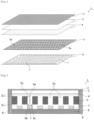
- Figure 1 shows a configuration image of an operation display panel-incorporated article of Embodiment 1.
- the operation display panel-incorporated article 1 is composed of a plate 2, a transparent base 3, a touch panel sheet 4 as a transparent conductive film, a light guide 5 and an LED array 6 as a light emitting element array. It is sequentially laminated.
- the plate 2 is located on the outer surface of the operation display panel-incorporated article, and the LED array 6 is configured to be located inside the article.
- a large number of LED light sources 7 are two-dimensionally arranged in the LED array 6.
- the light guide 5 guides the light emission direction of each LED light source 7 in the direction perpendicular to the substrate of the LED array 6.
- the LED array 6 is configured of, for example, a total of 6400 LED light sources with 32 vertical by 200 horizontal.
- One LED light source is composed of planar mounting type LEDs.
- a point light source is realized by the light of one LED light source, and this can be regarded as one dot, and one character or pattern can be represented by 8 ⁇ 8 dots or 16 ⁇ 16 dots.
- a 22-character by 3-line sentence can be expressed.
- the LED light source for example, one with a size of 2 mm ⁇ 2 mm and 700 to 1000 mcd (Millicandela) is used.
- the light guide 5 plays a role of making a character or a pattern formed of light emitted from the LED light source 7 clearly visible through the plate 2. Namely, when the light guides 5 are stacked on the LED array 6, a large number of guide holes 5a are arranged in accordance with the arrangement of the LED light sources 7 so that the guide holes 5a are arranged immediately above each respective LED light source 7.
- a Sycamore material is used for the wood veneer 2.
- a comparative experiment was conducted using a plurality of woods, and a qualitative evaluation was performed.
- the species of wood to be subjected to comparative experiments was selected on the basis of thinness of grain, fineness of grain, fineness of conduit and easiness of availability. Those with a thin grain are those with unclear winter grain.
- the reason for using thin conduits as the selection item is that when the conduits are thick, the conduits appear like fissures, which appears to direct light from light source leaks, resulting in a reduction of visibility.
- Figure 2 shows a schematic cross-sectional view of the operation display panel-incorporated article of the first embodiment.
- the plate 2, the transparent base 3, the touch panel sheet 4, the light guide 5 and the LED array 6 are stacked in order from the top and adhered to the housing 8.
- the obliquely emitted light (9b, 9c) is blocked by the light guide 5, and the emitted light reaches the wood veneer 2 as a straight light like 9a.
- the housing 8 is mainly made of ABS resin.
- the wood veneer 2 and the transparent substrate 3, or the transparent substrate 3 and the touch panel sheet 4 are bonded without providing a gap.
- a gap G 1 is provided between the touch panel sheet 4 and the light guide 5. This is because the light guide 5 is provided with the guide holes 5a, and when the touch panel sheet 4 and the light guide 5 are bonded, a stress variation occurs when operating the touch panel, which becomes a cause of a malfunction.
- a gap G 2 is provided between the light guide 5 and the LED light source 7. Since the number of LED light sources 7 provided in the LED array 6 and the number of guide holes 5a provided in the light guides 5 are several thousands, when the light guides 5 and the LED arrays 6 are stacked, there is a possibility that an arrangement error occurs. When the light guide 5 and the LED array 6 are bonded in a state where an error occurs, the light emitted from the LED light source 7 does not pass through the guide hole 5a and an accurate display cannot be performed. Therefore, by providing the gap G 2 , it is possible to prevent deterioration of display quality caused by an error in the arrangement of the LED light source 7 and the guide hole 5a. In addition, since the display quality can be maintained even if there are some errors, the manufacture becomes easy.
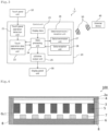
- Figure 3 shows a functional block diagram of the operation display panel-incorporated article of the Embodiment 1.
- the operation display panel-incorporated article 1 includes a touch panel unit 10, a control unit 20 and a display panel unit 30.
- the control unit 20 is provided with a touch panel operation detection unit 21, a touch operation data determination unit 22, display data 23, a data processing unit 24, an LED drive output unit 25, and a data transmission / reception unit 26.
- the data transmission / reception unit 26 includes a data transmission unit 27 and a data reception unit 28.
- the touch panel operation detection unit 21 disposed in the control unit 20 detects which position on the touch panel the user has touched.
- the data processing unit 24 receives the display data 23 and sends the data to the touch operation data determination unit 22.
- the touch operation data determination unit 22 determines what operation the user has performed based on the data obtained by the touch panel operation detection unit 21 and the display data 23, and the touch operation data obtained by the determination is sent to the data processing unit 24.
- the data processing unit 24 determines which LED is to be lighted in what way on the basis of the touch operation data determined by the touch operation data determination unit 22, and transmits the determined data to the LED drive output unit 25 for display on the display panel unit 30.
- the touch operation data sent to the data processing unit 24 is sent from the data sending unit 27 to an external device 40 via the means of communication 50.
- the user can control the external device 40 by operating the touch panel unit 10.
- the data receiving unit 28 receives data from the external device 40 via the communication means 50, sends said data to the data processing unit 24, and the data processing unit 24 determines which LED is to be lighted in what way, and the determined data is transmitted to the LED data drive output unit 25 and displayed on the display panel unit 30.
- the communication means 50 performs wireless communication.
- the present invention is not limited to this, and wired communication may be performed.
- the external device 40 not only household appliances such as an air conditioner and a lighting fixture, but also a portable information terminal such as a smartphone and a personal computer can be mentioned.
- the operation display panel-incorporated article 1 and the external device 40 might not directly communicate with each other, but could communicate with each other via an external server by wired or wireless communication.
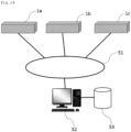
- Figure 14 shows a network configuration diagram using the operation display panel-incorporated article of the first embodiment.
- the operation display panel-incorporated articles (1a to 1c) can communicate with the computer 52 via the Internet 51, respectively, and the computer 52 is connected to the server 53 in a wired or wireless manner. Therefore, for example, position information of the operation display panel-incorporated article (1a to 1c) is registered in the server 53 in advance, and daily weather forecasting is performed from the computer 52 via the Internet 51 based on the information concerned. It is possible to transmit communications to the incorporated articles (1a to 1c) and display them on the display panel unit 30 of the operation display panel-incorporated article (1a to 1c).
- the server 53 may be connected to the computer 52 via the Internet 51.
- the LED display in the display panel unit 30 may be configured to be constantly displaying, or may be configured to be switched on / off in response to some event.
- an event for starting display occasions such as touch input by a user, a human body sensor that detects approach of someone, a sensor disposed at a room door, automatic display at every constant time or at a predetermined time, are considered.
- a displaying end event it is conceivable that a certain time has elapsed for the display, that the operation is automatically terminated at a specific time, or that the presence of a person is no longer recognized by the human sensor.
- the power source used for the operation display panel-incorporated article 1 may be either a battery or an external power source.
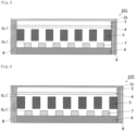
- Figure 4 shows a schematic cross-sectional view of the operation display panel-incorporated article of Embodiment 2.
- the veneer (or plate) 2a, the touch panel sheet 4 and the transparent base material 3 are stacked in order from the top.
- the touch panel sheet 4 needs to be adhered to a base having a small number of uneven surfaces in order to maintain the accuracy at the time of touch panel operation.
- the transparent substrate 3 is bonded to the touch panel sheet 4 as in Embodiment 1 because there are few irregularities on the surface, and is bonded in the present Embodiment as well.
- the plate 2 and the touch panel sheet 4 are not in direct contact with each other, structurally.
- the plate 2a is made of wood with very few irregularities on the surface.
- the plate 2, the transparent base material 3, and the touch panel sheet 4 are stacked in order from the top, it was necessary to set a gap G 1 between the touch panel sheet 4 and the light guide 5 to be stacked thereunder.
- the wood veneer 2a, the touch panel sheet 4 and the transparent substrate 3 are stacked in this order from the top, and it is unnecessary to provide a gap between the touch panel sheet and a light guide 5 to be stacked thereunder, in the configuration here. Thereby, thickness reduction of the operation display panel-incorporated article can be achieved.
- Figure 5 shows a schematic cross-sectional view of the operation display panel-incorporated article of Embodiment 3.
- a cloth material 2b is used instead of the wood veneer 2.
- the cloth material 2b for example, the appearance and texture similar to the wallpaper of a room can be obtained, and an operation display panel-incorporated article in which the user does not easily feel stress can be achieved.
- Figure 6 shows a schematic cross-sectional view of the operation display panel-incorporated article of Embodiment 4.
- a stone 2c is used instead of the wood veneer 2.
- the operation display panel-incorporated article can be set as an operation display panel incorporating article with high quality interior characteristics.
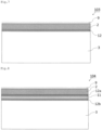
- Figure 7 shows an adhesion image diagram of the wood veneer and the transparent base material of Embodiment 5.
- the veneer (or plate) 2 and the transparent base 3 constituting the operation display panel-incorporated article 103 are adhered by an adhesive 12.
- Urethane coating is applied to the surface of the plate 2 to form a urethane layer 9, which prevents generation of scratches and adhesion of dirt.
- FIG 8 shows an adhesion image diagram of the veneer and the transparent substrate of Embodiment 6.
- the surface of the veneer 2 constituting the operation display panel built-in article 104 is covered by urethane layer 9 formed by a urethane coating to prevent generation of scratches and adhesion of dirt.
- a polyvinyl chloride film 11 is attached to the back surface of the veneer 2 as a backing material using an adhesive 12a. This is provided to reinforce the veneer 2. Since the polyvinyl chloride film 11 is a material with high transparency, it is possible to effectively reinforce the plate 2 with almost no influence on the transmittance. Furthermore, the veneer 2 and the transparent substrate 3 pasted with polyvinyl chloride film 11 are adhered by an adhesive 12b.
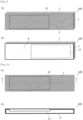
- Figure 9 is a perspective view of the operation display panel-incorporated article of Embodiment 7, (1) showing a perspective view from the front, and (2) showing a perspective view from the back.
- the operation display panel-incorporated article 105 is covered with the wood veneer 2 in a front view, and thus has a shape as if it were a single wooden board.
- An operation display panel unit 13 is disposed inside the operation display panel-incorporated article 105.
- the operation display panel unit 13 refers to the one including the wood veneer 2, transparent base 3, the touch panel sheet 4, the light guide 5 and the LED array 6 shown in Figure 2 , with the wood veneer being eliminated therefrom.
- the LED array 6 is provided with a large number of LED light sources, 7 similar to Embodiment 1.
- the wood veneer 2 is not attached to the back surface of the operation display panel-incorporated article 105, and the housing 8 is exposed.
- Figure 10 is an explanatory view of the operation display panel-incorporated article of Embodiment 7, (1) showing a front view, and (2) showing an A-A sectional view.
- the operation display panel unit 13 is disposed inside the operation display panel-incorporated article 105.
- the housing 8 is not in the shape of a rectangular parallelepiped, and the portion where the operation display panel unit 13 is disposed is in an open state.
- a touch control IC, a main microcomputer, a wireless communication device, a power supply, and the like are provided inside the housing 8.
- Figure 11 shows a perspective view of the operation display panel-incorporated article of Embodiment 8.
- the operation display panel-incorporated article 106 has a cylindrical shape.
- the plate 2d is formed of a flexible material, and is stuck on an outer peripheral side surface of the housing 80 in a curved state.
- the transparent base material and touch panel sheet which are not illustrated here are mentioned later.
- the housing 80 also has a substantially cylindrical shape, but the portion where the operation display panel units (130a to 130c) are disposed has an open shape.
- Figure 12 is an explanatory diagram of an operation display panel-incorporated article of Embodiment 8, (1) showing a front view, and (2) showing a B-B sectional view.
- operation display panel units (130a to 130c) are disposed inside the operation display panel-incorporated article 106.
- the operation display panel units (130a to 130c) are arranged to emit light in the direction of the outer peripheral surface from the axial center of the cylindrical operation display panel-incorporated article 106.
- Figure 13 shows an enlarged explanatory view of the operation display panel-incorporated article of Embodiment 8.
- the operation display panel unit (130a to 130c) is composed of the light guide 5 and the LED array 6, and the LED array 6 is provided with a large number of LED light sources 7 as in Embodiment 1.
- the veneer 2d, the transparent base 3d, and the touch panel sheet 4d have a substantially cylindrical shape conforming to the outer peripheral surface of the housing 80 and stuck together in order. Therefore, a gap G 3 is provided between the veneer 2d, the transparent base 3d, the touch panel sheet 4d and the operation display panel units (130a to 130c). Further, the gap between the operation display panel unit 130a and the operation display panel unit 130b, or between the operation display panel unit 130b and the operation display panel unit 130c is to be comprised of a housing 80.
- the present embodiment it is configured that sufficient visibility and operability can be obtained even if the gap G 3 and the casing 80 portion between the operation display panel units (130a to 130c) are provided.
- the range of the gap G 3 can be narrowed, or the casing 80 portion between panel units (130a - 130c) can be reduced.
- the operation display panel units (130a to 130c) are provided only at about a half circumference of the cylindrical shape, but display may be provided on the entire outer peripheral surface so as to cover the entire outer peripheral surface of the operation display panel-incorporated article 106.
- the cylindrical operation display panel-incorporated article As described above, by forming the cylindrical operation display panel-incorporated article, it is possible to obtain an article with high quality interior goods.
- the operation display panel-incorporated article 106 is not only high in the interior characteristics due to using natural materials but also gives a good touch by using the curved-plate shaped wood veneer 2d, and its texture can be enjoyed at each operation and presents a high quality experience to the user.
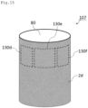
- Figure 15 shows a perspective view of the operation display panel-incorporated article of Embodiment 9.
- the outer shape of the operation display panel-incorporated article 107 has a cylindrical shape, like the operation display panel-incorporated article 106 of Embodiment 8.
- the plate 2d is formed of a flexible material, and is stuck on the outer peripheral side surface of the housing 80 in a curved state.
- the transparent base material and touch panel sheet which are not illustrated here are mentioned later.
- the housing 80 also has a substantially cylindrical shape, but the portion where the operation display panel units (130d - 130f) are disposed has an opening shape.
- Figure 16 is an explanatory diagram of an operation display panel-incorporated article of Embodiment 9, (1) showing a front view, (2) showing a C-C sectional view indicated in (1).
- operation display panel units (130d to 130f) are disposed inside the operation display panel-incorporated article 107.
- the operation display panel units (130d - 130f) are arranged to emit light in the direction of the outer peripheral surface from the axial center of the cylindrical operation display panel-incorporated article 107.
- Figure 17 shows an enlarged explanatory view of the operation display panel-incorporated article of Embodiment 9.
- the operation display panel unit (130d - 130f) comprises a light guide 5d and an LED array 6d, and the LED array 6d is provided with a large number of LED light sources 7 as in Embodiment 1.
- Embodiment 8 While all the operation display panel units (130a - 130c) in Embodiment 8 have a flat board shape, in the operation display panel units (130d - 130f), both the light guide 5d and the LED array 6d being used are flexible, and unlike Embodiment 8, the operation display panel unit (130d to 130f) has a curved shape that is matched to the outer peripheral surface shape of the casing 80, having a substantially cylindrical shape, and the shape of the plate 2d, the transparent base 3d, the touch panel sheet 4d, as thus disposed. In accordance with the shape of the sheet 4d, it has a curved shape and is thus disposed. Therefore, the configuration has high visibility and operability at the time of display.
- the space between the operation display panel unit 130d and the operation display panel unit 130e, or the operation display panel unit 130e and the operation display panel unit 130f is configured by the housing 80
- the portion of the housing 80 among operation panel units (130d - 130f) may be configured to be reduced as long as enough strength of the housing 80 can be obtained. By this, display range can be expanded and operability can be improved.
- operation display units (130d - 130f) are provided only in approximately half of the cylindrical shape, but one may let the operation display unit cover the entire outer peripheral surface of the panel-incorporated article 107, so that the display can be made on the entire side surface.
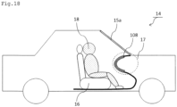
- Figure 18 shows a schematic image view of an operation display panel-incorporated article of Embodiment 10.
- the automobile 14 is provided with a windshield 15a, a seat 16, and an instrument panel 17, and a driver 18 sits on the seat 16.
- an operation display panel-incorporated article 108 is provided as a part of the instrument panel 17, as a part of the instrument panel 17, as a part of the instrument panel 17, an operation display panel-incorporated article 108 is provided.
- the headrest of the seat 16 seen from the rear seat (not shown), the back of the seat 16 and the ceiling of the automobile 14 may be used as the operation display panel-incorporated article.
- a component where a panel for controlling air conditioning and lighting is provided may be used as the operation display panel-incorporated article.
- Figure 19 shows an enlarged explanatory view of the operation display panel-incorporated article of Embodiment 10.
- the operation display panel-incorporated article 108 As shown in Figure 19 , on the surface of the operation display panel-incorporated article 108, a resin 2e produced so as to mimic the appearance and touch of wood derived from nature is used. Since the resin 2e has a curved surface shape in accordance with the shape of the instrument panel 17, a flexible material is used for the operation display panel units (130g to 130i) as in Embodiment 9. Although not shown in detail here, the operation display panel-incorporated article 108 is not used at a location where a constant display is required, such as a speedometer or a tachometer, but is configured to be used only for a place where constant display is not necessary. Other places, such as a clock or watch, do not use it.
- a constant display such as a speedometer or a tachometer
- Figure 20 shows a schematic image view of the operation display panel-incorporated article of Embodiment 11.
- a car door 60 is a door on the right side of a front seat of a car in general.
- the car door 60 is provided with a side glass 15b, a door inner handle 61, an operation display panel-incorporated article 109 which is a door trim, and an operation display panel-incorporated article 110 which is a door armrest.
- the operation display panel-incorporated article 109 is provided with the operation display panel unit 13a, and the surface is covered with a thin layer made of a resin 2f.
- the operation display panel unit 13a is disposed between the side glass 15b and the operation display panel-incorporated article 110 which is a door armrest, the display does not impede the other functions and when the display is not performed, it does not become a visual nuisance because the panel constitutes a part of the look of a usual door trim.
- the operation display panel-incorporated article 110 is furnished with the operation display panel unit 13b, and the surface is covered with a thin layer made of a resin 2f.
- the operation display panel unit 13b is generally disposed at a position where a power window switch is provided, and by touching the operation display panel unit 13b, the side glass 15b can be opened and closed.
- a means for preventing an accident by erroneous operation may be disposed on the inside or the outside of the operation display panel-incorporated article (109, 110).
- the thin layer provided in the operation display panel-incorporated article 109 and the thin layer provided in the operation display panel-incorporated article 110 are both made of the resin 2f, different resins may be used.
- Embodiment 9 by making the operation display panel unit flexible, it becomes possible to incorporate the operation display panel unit into articles of various shapes. Therefore, for example, a chair, a desk, a table, a sofa, a bed, a rack, a shelf, a curtain, a knick-knack or the like used on a daily basis may be used as the operation display panel-incorporated article.
- the present invention is useful as a controller of a home appliance, a display of an electronic device, or an operation display device mounted on a movable body such as a car.
Landscapes
- Engineering & Computer Science (AREA)
- Physics & Mathematics (AREA)
- General Physics & Mathematics (AREA)
- Theoretical Computer Science (AREA)
- General Engineering & Computer Science (AREA)
- Transportation (AREA)
- Combustion & Propulsion (AREA)
- Mechanical Engineering (AREA)
- Chemical & Material Sciences (AREA)
- Optics & Photonics (AREA)
- Human Computer Interaction (AREA)
- Illuminated Signs And Luminous Advertising (AREA)
- Devices For Indicating Variable Information By Combining Individual Elements (AREA)
- Circuit For Audible Band Transducer (AREA)
Claims (15)
- Gegenstand mit eingebauter Anzeigetafel, umfassend:eine dünne Schicht (2), die aus einem aus der Natur stammenden Holz, einer Naturfaser, einem Naturleder oder einem Naturstein oder aus einem Harz, einer Kunstfaser oder einem Kunststein, die hergestellt sind, um ein natürliches Aussehen zu imitieren, besteht und die auf der Umfangsoberfläche des Gehäuses angeordnet ist, sodass die dünne Schicht mindestens die gesamte Anzeigetafel mit einem an der Umfangsoberfläche des Gehäuses integrierten Berührungssensor abdeckt; undeine Tafel, die mit mindestens einem transparenten Basismaterial (3), einem übergeordneten leitfähigen Blatt (4), einem lichtemittierenden Elementenarray (6), das lichtemittierende Elemente (7) aufweist, die in einem 2-dimensionalen Array angeordnet sind, und einem Lichtleiter (5) versehen ist;wobei die Dicke der dünnen Schicht (2) und die Helligkeit der Tafel so eingestellt sind, dass die auf der betreffenden Tafel angezeigten Inhalte visuell erkannt werden können,dadurch gekennzeichnet, dass der Lichtleiter (5) Durchgangslöcher aufweist, die entlang der optischen Achse jedes lichtemittierenden Elements (7) angeordnet sind, um die Lichtemissionsrichtung des lichtemittierenden Elements (7) in die Richtung senkrecht zu dem lichtemittierenden Elementenarray (6) zu führen.
- Gegenstand mit eingebauter Anzeigetafel nach Anspruch 1, wobei die dünne Schicht (2) eine Lichtdurchlässigkeit im Bereich von 1 bis 50 % aufweist.
- Gegenstand mit eingebauter Anzeigetafel nach Anspruch 1 oder 2, wobei die dünne Schicht (2) ein Furnier oder Sperrholz aus Holz oder ein durch Formen von Holzspänen erhaltenes Substrat ist und eine Dicke im Bereich von 0,1 bis 0,5 mm aufweist.
- Gegenstand mit eingebauter Anzeigetafel nach Anspruch 1 oder 2, wobei die dünne Schicht (2) ein aus Naturfasern bestehendes gewebtes oder nicht gewebtes Substrat ist.
- Gegenstand mit eingebauter Anzeigetafel nach einem der Ansprüche 1 bis 4, wobei die dünne Schicht (2) als transparente Schutzschicht auf der vorderen Oberfläche davon bereitgestellt ist.
- Gegenstand mit eingebauter Anzeigetafel nach einem der Ansprüche 1 bis 5, wobei die dünne Schicht (2) auf ihrer hinteren Oberfläche eine transparente Verstärkungsschicht bereitstellt.
- Gegenstand mit eingebauter Anzeigetafel nach einem der Ansprüche 1 bis 6, wobei der Lichtleiter (5) ein undurchsichtiges Basismaterial dunkler Farbe ist, das auf das Substrat des lichtemittierenden Elementenarrays (6) laminiert ist und das gesamte lichtemittierende Elementenarray umschließt.
- Gegenstand mit eingebauter Anzeigetafel nach Anspruch 7, wobei der Lichtleiter (5) einen Durchmesser des Durchgangslochs aufweist, der gleich oder größer ist als der Durchmesser des lichtemittierenden Bereichs des lichtemittierenden Elements, und das Aspektverhältnis im Bereich von 0,5 bis 3,0 liegt.
- Gegenstand mit eingebauter Anzeigetafel nach einem der Ansprüche 1 bis 8, wobei die Tafel aus einem transparenten Substrat (3), einem transparenten leitfähigen Blatt (4), einem Lichtleiter (5) und einem lichtemittierenden Elementenarray (6) besteht, die nacheinander laminiert sind, und wobei das transparente Substrat (3) und das transparente leitfähige Blatt (4) in engem Kontakt sind, und
wobei zwischen dem transparenten leitfähigen Blatt (4) und dem Lichtleiter (5) ein Spalt bereitgestellt wird. - Gegenstand mit eingebauter Anzeigetafel nach einem der Ansprüche 1 bis 8, wobei die Tafel, ein transparentes leitfähiges Blatt (4), eine transparente Basis (3), ein Lichtleiter (5) und ein lichtemittierendes Elementenarray (6) nacheinander laminiert sind, und wobei das transparente leitfähige Blatt (4) und die transparente Basis (3) in engem Kontakt miteinander sind.
- Gegenstand mit eingebauter Anzeigetafel nach einem der Ansprüche 7 bis 10, wobei die lichtemittierenden Elemente (7) des lichtemittierenden Elementenarrays (6) und die Durchgangslöcher des Lichtleiters (5) das gleiche Muster aufweisen und beide mit dem gleichen Abstand angeordnet sind, und der Abstand 5 mm oder weniger beträgt.
- Gegenstand mit integrierter Anzeigetafel nach einem der Ansprüche 1 bis 11, ferner umfassend ein flexibles transparentes Substrat (3), ein flexibles transparentes leitendes Blatt (4), einen flexiblen Lichtleiter (5) und ein flexibles Substrat des lichtemittierenden Elementenarrays (6).
- Gegenstand mit eingebauter Anzeigetafel nach einem der Ansprüche 1 bis 12, wobei die gesamte oder ein Teil der äußeren Umfangsoberfläche des Gehäuses eine gekrümmte Form aufweist und die Tafel so eingebaut ist, dass sie an der gekrümmten Oberfläche anliegt.
- Gegenstand mit eingebauter Anzeigetafel nach einem der Ansprüche 1 bis 13, ferner umfassend mindestens eines der Folgenden:die Tafelsteuereinheit zum Steuern der vom Berührungssensor ermittelten Tafeldaten und steuert das lichtemittierende Elementenarray nach dem auf dem Bestimmungsergebnis basierenden Anzeigeinhalt der Anzeigetafel an;die Tafelsteuereinheit bestimmt Daten von dem Berührungssensor und steuert das lichtemittierende Elementenarray nach dem auf dem Bestimmungsergebnis basierenden Anzeigeinhalt der Anzeigetafel an und überträgt Daten nach außen durch verdrahtete Kommunikation oder drahtlose Kommunikation;die Tafelsteuereinheit empfängt Daten von außen über drahtlose Kommunikation, und steuert das lichtemittierende Elementenarray nach dem Anzeigeinhalt der Anzeigetafel basierend auf dem Bestimmungsergebnis der empfangenen Daten.
- Gegenstand mit eingebauter Anzeigetafel nach einem der Ansprüche 1 bis 14, ferner umfassend einen Lautsprecher oder ein Mikrofon.
Applications Claiming Priority (2)
| Application Number | Priority Date | Filing Date | Title |
|---|---|---|---|
| PCT/JP2017/039017 WO2019082399A1 (ja) | 2017-10-28 | 2017-10-28 | 操作表示パネル組込物品 |
| PCT/JP2018/040206 WO2019083051A1 (ja) | 2017-10-28 | 2018-10-29 | 操作表示パネル組込物品 |
Publications (4)
| Publication Number | Publication Date |
|---|---|
| EP3579217A1 EP3579217A1 (de) | 2019-12-11 |
| EP3579217A4 EP3579217A4 (de) | 2020-12-16 |
| EP3579217B1 true EP3579217B1 (de) | 2025-04-16 |
| EP3579217B8 EP3579217B8 (de) | 2025-06-04 |
Family
ID=63104411
Family Applications (1)
| Application Number | Title | Priority Date | Filing Date |
|---|---|---|---|
| EP18870982.8A Active EP3579217B8 (de) | 2017-10-28 | 2018-10-29 | Produkt mit eingebauter betriebsanzeigetafel |
Country Status (6)
| Country | Link |
|---|---|
| US (2) | US11656699B2 (de) |
| EP (1) | EP3579217B8 (de) |
| JP (2) | JP6370519B1 (de) |
| CN (1) | CN111386564A (de) |
| TW (1) | TWI678578B (de) |
| WO (2) | WO2019082399A1 (de) |
Families Citing this family (25)
| Publication number | Priority date | Publication date | Assignee | Title |
|---|---|---|---|---|
| JP6370519B1 (ja) * | 2017-10-28 | 2018-08-08 | mui Lab株式会社 | 操作表示パネル組込物品 |
| WO2019165441A1 (en) * | 2018-02-26 | 2019-08-29 | Shanghai Yanfeng Jinqiao Automotive Trim Systems Co. Ltd. | Vehicle interior component |
| JP7126320B2 (ja) * | 2018-03-16 | 2022-08-26 | 株式会社ジャパンディスプレイ | 表示装置 |
| US20220176821A1 (en) * | 2019-04-29 | 2022-06-09 | Corning Incorporated | Display with underlying decorative layer |
| JP7432327B2 (ja) * | 2019-09-04 | 2024-02-16 | 株式会社ジャパンディスプレイ | 表示システム |
| JP6784422B1 (ja) * | 2019-09-05 | 2020-11-11 | mui Lab株式会社 | 描画内容を記憶する操作表示パネル組込物品及びシステム |
| DE102019127630A1 (de) * | 2019-10-14 | 2021-04-15 | Leonhard Kurz Stiftung & Co. Kg | Dekorfolie, Dekorfolienkörper, Displaykörper sowie Verfahren zu dessen Herstellung |
| KR20220132007A (ko) | 2020-02-05 | 2022-09-29 | 터치우드 랩스, 인크. | 대화형 디스플레이 표면 |
| WO2021181716A1 (ja) * | 2020-03-08 | 2021-09-16 | mui Lab株式会社 | 操作表示パネル組込物品 |
| JP7516820B2 (ja) * | 2020-03-31 | 2024-07-17 | Toppanホールディングス株式会社 | 表示装置 |
| JP6784430B1 (ja) * | 2020-04-07 | 2020-11-11 | mui Lab株式会社 | 表示パネル |
| CN111312098A (zh) * | 2020-04-23 | 2020-06-19 | 大连集思特科技有限公司 | 一种透明触控led显示屏 |
| JP7537128B2 (ja) * | 2020-05-26 | 2024-08-21 | Toppanホールディングス株式会社 | 表示装置 |
| WO2022070564A1 (ja) | 2020-09-29 | 2022-04-07 | mui Lab株式会社 | 表示パネル及び操作表示パネル |
| CN112419889A (zh) * | 2020-10-13 | 2021-02-26 | 康佳集团股份有限公司 | 一种显示墙纸及显示墙 |
| CN116997949A (zh) * | 2021-03-08 | 2023-11-03 | 京瓷株式会社 | 显示装置 |
| TWI842985B (zh) | 2021-04-06 | 2024-05-21 | 南亞塑膠工業股份有限公司 | 皮革材料及汽車儀表板複合結構 |
| JP7659810B2 (ja) * | 2021-04-27 | 2025-04-10 | 株式会社タテイシ広美社 | 発光式表示パネルの製造方法 |
| WO2024018291A1 (en) * | 2022-07-22 | 2024-01-25 | Centitvc - Centro De Nanotecnologia E Materiais Técnicos Funcionais E Inteligentes | Natural stone panel with surface lighting properties and respective manufacturing process |
| EP4310392A1 (de) * | 2022-07-22 | 2024-01-24 | CENTITVC - Centro de Nanotecnologia e Materiais Tecnicos, Funcionais e Inteligentes | Natursteinplatte mit oberflächenbeleuchtungseigenschaften und entsprechendes herstellungsverfahren |
| TWI828267B (zh) * | 2022-08-11 | 2024-01-01 | 造隆股份有限公司 | 具有可薄型化結構的數位儀錶 |
| JP2024100247A (ja) | 2023-01-13 | 2024-07-26 | 株式会社ジャパンディスプレイ | 検出装置 |
| WO2025029187A1 (en) * | 2023-08-02 | 2025-02-06 | Razer (Asia-Pacific) Pte. Ltd. | Touch control module |
| KR20250102570A (ko) | 2023-12-28 | 2025-07-07 | 현대모비스 주식회사 | 프로젝션을 이용한 조작계를 포함하는 칵핏 시스템 |
| JP2025173798A (ja) * | 2024-05-15 | 2025-11-28 | 株式会社東海理化電機製作所 | スイッチ |
Citations (3)
| Publication number | Priority date | Publication date | Assignee | Title |
|---|---|---|---|---|
| US7097913B2 (en) * | 2000-05-24 | 2006-08-29 | Kabushiki Kaisha Kawai Gakki Seisakusho | Decorative article having translucent wood veneer |
| CN105976711A (zh) * | 2016-05-31 | 2016-09-28 | 上海铭酿电子科技有限公司 | 一种可静态或动态显示图像的智能板材以及家具、房屋 |
| WO2016196532A1 (en) * | 2015-06-02 | 2016-12-08 | Corning Incorporated | Multi-functional material system for surface display unit |
Family Cites Families (51)
| Publication number | Priority date | Publication date | Assignee | Title |
|---|---|---|---|---|
| JPS586124A (ja) * | 1981-07-02 | 1983-01-13 | Toshiba Mach Co Ltd | 半導体気相成長装置 |
| JP2571743Y2 (ja) * | 1991-12-20 | 1998-05-18 | タキロン株式会社 | ドットマトリクス発光表示体用表面集光板 |
| JP2901506B2 (ja) * | 1994-10-24 | 1999-06-07 | スタンレー電気株式会社 | Ledドットマトリクス表示ユニット |
| DE19902487A1 (de) | 1999-01-22 | 2000-08-17 | Mekra Lang Gmbh & Co Kg | Rückspiegel |
| JP4469463B2 (ja) * | 2000-05-30 | 2010-05-26 | 株式会社河合楽器製作所 | 木質化粧成形品 |
| JP3613257B2 (ja) * | 2001-05-02 | 2005-01-26 | セイコーエプソン株式会社 | カラー表示用基板、カラーフィルタ用基板、カラー発光用基板、カラー表示用基板の製造方法、電気光学装置、電子機器 |
| JP4318961B2 (ja) | 2003-05-27 | 2009-08-26 | 株式会社ソニー・コンピュータエンタテインメント | 表示装置およびこの表示装置を備えた電子機器 |
| JP2005062441A (ja) * | 2003-08-12 | 2005-03-10 | Towa Meccs Corp | 表示装置 |
| EP1640756A1 (de) * | 2004-09-27 | 2006-03-29 | Barco N.V. | Methode und System zur Beleuchtung |
| JP5214109B2 (ja) * | 2006-02-03 | 2013-06-19 | 富士通モバイルコミュニケーションズ株式会社 | 表示構造を備えた物品 |
| KR101297216B1 (ko) * | 2006-09-05 | 2013-08-16 | 삼성디스플레이 주식회사 | 터치패널, 이를 갖는 터치스크린 표시장치 및 이의제조방법 |
| ITTO20060818A1 (it) * | 2006-11-16 | 2008-05-17 | Indesit Co Spa | Elettrodomestico con dispositivi di comando d'utente del tipo a contatto |
| EP1930800A1 (de) * | 2006-12-05 | 2008-06-11 | Electronics and Telecommunications Research Institute | Taktile und visuelle Anzeigevorrichtung |
| US20090058118A1 (en) | 2007-08-31 | 2009-03-05 | Lear Corporation | Trim panel for a motor vehicle and method of manufacturing |
| JP4900877B2 (ja) * | 2007-10-18 | 2012-03-21 | 株式会社デンソー | 車両用表示装置 |
| JP2009209531A (ja) * | 2008-02-29 | 2009-09-17 | Tanaka Mokuzai Kogyo Kk | 発光機能付き積層体 |
| JP2010120487A (ja) * | 2008-11-19 | 2010-06-03 | Kojima Press Industry Co Ltd | 車室内スイッチ装置 |
| JP5447945B2 (ja) * | 2009-10-31 | 2014-03-19 | 田中木材工業株式会社 | 発光機能付き筐体およびその製造方法 |
| US9013515B2 (en) | 2010-12-02 | 2015-04-21 | Disney Enterprises, Inc. | Emissive display blended with diffuse reflection |
| US8866708B2 (en) * | 2011-01-21 | 2014-10-21 | Peter Sui Lun Fong | Light emitting diode switch device and array |
| JP5670827B2 (ja) * | 2011-05-13 | 2015-02-18 | 富士フイルム株式会社 | 導電シート及びタッチパネル |
| US9478590B2 (en) * | 2012-05-22 | 2016-10-25 | Superc-Touch Corporation | In-cell OLED touch display panel structure with metal layer for sensing |
| FI20120340L (fi) * | 2012-10-08 | 2014-04-09 | Canatu Oy | Kosketusrajapintalaite ja rakenne |
| JP6056416B2 (ja) * | 2012-11-27 | 2017-01-11 | 大日本印刷株式会社 | タッチスイッチ部材及びタッチスイッチ装置 |
| JP6248398B2 (ja) * | 2013-03-06 | 2017-12-20 | 大日本印刷株式会社 | 情報表示媒体 |
| CN105593289A (zh) * | 2013-10-04 | 2016-05-18 | 亚克朗聚合物系统公司 | 树脂组合物、基底和制造电子装置的方法 |
| CN106988084A (zh) * | 2013-10-25 | 2017-07-28 | 东芝生活电器株式会社 | 操作面板以及洗衣机 |
| JP2015118398A (ja) * | 2013-12-16 | 2015-06-25 | 田中木材工業株式会社 | 発光機能付き筐体 |
| US9311865B1 (en) * | 2013-12-18 | 2016-04-12 | Amazon Technologies, Inc. | Display with active matrix lightguide |
| JP2015161835A (ja) * | 2014-02-27 | 2015-09-07 | 大日本印刷株式会社 | 情報表示体 |
| TWI667270B (zh) * | 2014-05-26 | 2019-08-01 | 日商王子控股股份有限公司 | 微細纖維及含微細纖維片的製造方法、由其得到的片及積層樹脂的樹脂複合體 |
| JP6331020B2 (ja) * | 2014-09-03 | 2018-05-30 | パナソニックIpマネジメント株式会社 | 導光板表示装置 |
| JP6415239B2 (ja) * | 2014-10-21 | 2018-10-31 | 株式会社クラレ | 光透過性皮革調シート、皮革調発光シート、及び皮革調発光ベルト |
| US9257104B1 (en) * | 2015-01-26 | 2016-02-09 | Patrick Cherry | Layered wood and silk guitar picks |
| GB2555308B (en) * | 2015-06-19 | 2021-01-06 | Nissha Co Ltd | Touch sensor provided with a circulaly polarizing plate, and image display device |
| GB2547880A (en) * | 2016-01-06 | 2017-09-06 | Merenda Ltd | Veneers |
| KR102524805B1 (ko) * | 2016-02-12 | 2023-04-25 | 삼성전자주식회사 | 광원 모듈, 디스플레이 패널 및 이를 구비한 디스플레이 장치 |
| KR102339634B1 (ko) | 2016-03-11 | 2021-12-16 | 도레이 카부시키가이샤 | 광투과형 도전 적층체, 그것을 사용한 광투과형 도전 성형체 |
| CN105877022A (zh) * | 2016-06-02 | 2016-08-24 | 李志忠 | 智能仿真饰品、智能仿真饰品的实现方法及提醒方法 |
| US20170371087A1 (en) * | 2016-06-22 | 2017-12-28 | Apple Inc. | Displays with Ramped Light Guide Layers and Multidirectional Light-Emitting Diodes |
| US10638618B1 (en) * | 2016-07-12 | 2020-04-28 | Apple Inc. | Cosmetic integration of displays |
| KR20180014401A (ko) * | 2016-07-29 | 2018-02-08 | 엘지디스플레이 주식회사 | 광원 모듈 및 이를 포함하는 백라이트 유닛 |
| US10310174B2 (en) * | 2016-07-29 | 2019-06-04 | Japan Display Inc. | Light source device and light source unit comprising the same |
| JP6202698B1 (ja) * | 2016-09-28 | 2017-09-27 | Boeジャパン株式会社 | 筐体及びシステム |
| CN106486463B (zh) * | 2016-11-23 | 2019-09-27 | 上海天马微电子有限公司 | 一种阵列基板、显示面板及显示装置 |
| JP2019020448A (ja) * | 2017-07-11 | 2019-02-07 | 株式会社ジャパンディスプレイ | 表示装置 |
| US10474417B2 (en) * | 2017-07-20 | 2019-11-12 | Apple Inc. | Electronic device with sensors and display devices |
| US10561019B2 (en) * | 2017-08-25 | 2020-02-11 | Tactotek Oy | Ecological multilayer structure for hosting electronics and related method of manufacture |
| JP6811446B2 (ja) * | 2017-08-25 | 2021-01-13 | パナソニックIpマネジメント株式会社 | 樹脂部品およびそれを用いた表示装置 |
| EP4516750A3 (de) * | 2017-09-12 | 2025-10-08 | Corning Incorporated | Taktile elemente für deadfronted-glas und verfahren zur herstellung davon |
| JP6370519B1 (ja) * | 2017-10-28 | 2018-08-08 | mui Lab株式会社 | 操作表示パネル組込物品 |
-
2017
- 2017-10-28 JP JP2018512632A patent/JP6370519B1/ja active Active
- 2017-10-28 WO PCT/JP2017/039017 patent/WO2019082399A1/ja not_active Ceased
-
2018
- 2018-07-06 TW TW107123592A patent/TWI678578B/zh active
- 2018-10-29 US US16/471,005 patent/US11656699B2/en active Active
- 2018-10-29 CN CN201880045129.0A patent/CN111386564A/zh active Pending
- 2018-10-29 JP JP2019519355A patent/JP6775851B2/ja active Active
- 2018-10-29 WO PCT/JP2018/040206 patent/WO2019083051A1/ja not_active Ceased
- 2018-10-29 EP EP18870982.8A patent/EP3579217B8/de active Active
-
2022
- 2022-12-19 US US18/084,225 patent/US12254788B2/en active Active
Patent Citations (3)
| Publication number | Priority date | Publication date | Assignee | Title |
|---|---|---|---|---|
| US7097913B2 (en) * | 2000-05-24 | 2006-08-29 | Kabushiki Kaisha Kawai Gakki Seisakusho | Decorative article having translucent wood veneer |
| WO2016196532A1 (en) * | 2015-06-02 | 2016-12-08 | Corning Incorporated | Multi-functional material system for surface display unit |
| CN105976711A (zh) * | 2016-05-31 | 2016-09-28 | 上海铭酿电子科技有限公司 | 一种可静态或动态显示图像的智能板材以及家具、房屋 |
Also Published As
| Publication number | Publication date |
|---|---|
| JPWO2019082399A1 (ja) | 2019-11-14 |
| TW201917462A (zh) | 2019-05-01 |
| JP6370519B1 (ja) | 2018-08-08 |
| EP3579217B8 (de) | 2025-06-04 |
| WO2019083051A1 (ja) | 2019-05-02 |
| EP3579217A4 (de) | 2020-12-16 |
| CN111386564A (zh) | 2020-07-07 |
| US20230152914A1 (en) | 2023-05-18 |
| WO2019082399A1 (ja) | 2019-05-02 |
| US20200241675A1 (en) | 2020-07-30 |
| JPWO2019083051A1 (ja) | 2020-09-24 |
| US11656699B2 (en) | 2023-05-23 |
| EP3579217A1 (de) | 2019-12-11 |
| JP6775851B2 (ja) | 2020-10-28 |
| TWI678578B (zh) | 2019-12-01 |
| US12254788B2 (en) | 2025-03-18 |
Similar Documents
| Publication | Publication Date | Title |
|---|---|---|
| US12254788B2 (en) | Product with incorporated operation display panel | |
| US11104229B2 (en) | Vehicle interior component | |
| US11760276B2 (en) | Vehicle interior component | |
| US11061475B2 (en) | Vehicle interior component | |
| US10821889B2 (en) | Vehicle interior component | |
| US12083953B2 (en) | Vehicle interior component | |
| US11701968B2 (en) | Vehicle interior component having a composite structure providing a user interface | |
| US11214147B2 (en) | Vehicle interior component | |
| CN111516617A (zh) | 用于车辆内饰的触控模块及包括该触控模块的内饰和车辆 | |
| US20240166048A1 (en) | Smart surface, center console for vehicle, and vehicle | |
| JP6677666B2 (ja) | 表示装置 | |
| TWI832629B (zh) | 汽車控制單元、汽車內部功能部件、控制汽車內部功能部件的方法、車輛 | |
| CN114987357A (zh) | 透光表皮结构、具有透光和触摸系统的装饰表皮和车辆 | |
| CN207782764U (zh) | 触控装置以及搭载该种装置的车辆 | |
| CN111422066A (zh) | 用于车辆客舱的面板元件 | |
| CN222905459U (zh) | 一种智能感应触控pu内饰件 | |
| JP2021165823A (ja) | 表示パネル | |
| CN112297565A (zh) | 采用无缝化设计的智能显示包覆件、智能显示系统及汽车 |
Legal Events
| Date | Code | Title | Description |
|---|---|---|---|
| STAA | Information on the status of an ep patent application or granted ep patent |
Free format text: STATUS: THE INTERNATIONAL PUBLICATION HAS BEEN MADE |
|
| PUAI | Public reference made under article 153(3) epc to a published international application that has entered the european phase |
Free format text: ORIGINAL CODE: 0009012 |
|
| STAA | Information on the status of an ep patent application or granted ep patent |
Free format text: STATUS: REQUEST FOR EXAMINATION WAS MADE |
|
| 17P | Request for examination filed |
Effective date: 20191104 |
|
| AK | Designated contracting states |
Kind code of ref document: A1 Designated state(s): AL AT BE BG CH CY CZ DE DK EE ES FI FR GB GR HR HU IE IS IT LI LT LU LV MC MK MT NL NO PL PT RO RS SE SI SK SM TR |
|
| AX | Request for extension of the european patent |
Extension state: BA ME |
|
| A4 | Supplementary search report drawn up and despatched |
Effective date: 20201116 |
|
| RIC1 | Information provided on ipc code assigned before grant |
Ipc: G09F 23/00 20060101ALI20201110BHEP Ipc: B60K 35/00 20060101ALI20201110BHEP Ipc: G06F 3/041 20060101ALI20201110BHEP Ipc: G09F 9/33 20060101ALI20201110BHEP Ipc: B60K 37/00 20060101ALI20201110BHEP Ipc: B32B 17/00 20060101ALI20201110BHEP Ipc: G09F 9/00 20060101AFI20201110BHEP |
|
| DAV | Request for validation of the european patent (deleted) | ||
| DAX | Request for extension of the european patent (deleted) | ||
| STAA | Information on the status of an ep patent application or granted ep patent |
Free format text: STATUS: EXAMINATION IS IN PROGRESS |
|
| 17Q | First examination report despatched |
Effective date: 20230206 |
|
| GRAP | Despatch of communication of intention to grant a patent |
Free format text: ORIGINAL CODE: EPIDOSNIGR1 |
|
| STAA | Information on the status of an ep patent application or granted ep patent |
Free format text: STATUS: GRANT OF PATENT IS INTENDED |
|
| INTG | Intention to grant announced |
Effective date: 20241111 |
|
| GRAS | Grant fee paid |
Free format text: ORIGINAL CODE: EPIDOSNIGR3 |
|
| GRAA | (expected) grant |
Free format text: ORIGINAL CODE: 0009210 |
|
| STAA | Information on the status of an ep patent application or granted ep patent |
Free format text: STATUS: THE PATENT HAS BEEN GRANTED |
|
| GRAT | Correction requested after decision to grant or after decision to maintain patent in amended form |
Free format text: ORIGINAL CODE: EPIDOSNCDEC |
|
| AK | Designated contracting states |
Kind code of ref document: B1 Designated state(s): AL AT BE BG CH CY CZ DE DK EE ES FI FR GB GR HR HU IE IS IT LI LT LU LV MC MK MT NL NO PL PT RO RS SE SI SK SM TR |
|
| REG | Reference to a national code |
Ref country code: GB Ref legal event code: FG4D |
|
| REG | Reference to a national code |
Ref country code: CH Ref legal event code: EP Ref country code: DE Ref legal event code: R096 Ref document number: 602018081199 Country of ref document: DE |
|
| RAP4 | Party data changed (patent owner data changed or rights of a patent transferred) |
Owner name: MUI LAB, INC. |
|
| REG | Reference to a national code |
Ref country code: IE Ref legal event code: FG4D |
|
| REG | Reference to a national code |
Ref country code: CH Ref legal event code: PK Free format text: BERICHTIGUNG B8 |
|
| RAP4 | Party data changed (patent owner data changed or rights of a patent transferred) |
Owner name: MUI LAB, INC. |
|
| REG | Reference to a national code |
Ref country code: SE Ref legal event code: TRGR |
|
| REG | Reference to a national code |
Ref country code: NL Ref legal event code: MP Effective date: 20250416 |
|
| PG25 | Lapsed in a contracting state [announced via postgrant information from national office to epo] |
Ref country code: NL Free format text: LAPSE BECAUSE OF FAILURE TO SUBMIT A TRANSLATION OF THE DESCRIPTION OR TO PAY THE FEE WITHIN THE PRESCRIBED TIME-LIMIT Effective date: 20250416 |
|
| REG | Reference to a national code |
Ref country code: AT Ref legal event code: MK05 Ref document number: 1786330 Country of ref document: AT Kind code of ref document: T Effective date: 20250416 |
|
| P01 | Opt-out of the competence of the unified patent court (upc) registered |
Free format text: CASE NUMBER: UPC_APP_3535_3579217/2025 Effective date: 20250818 |
|
| PG25 | Lapsed in a contracting state [announced via postgrant information from national office to epo] |
Ref country code: PT Free format text: LAPSE BECAUSE OF FAILURE TO SUBMIT A TRANSLATION OF THE DESCRIPTION OR TO PAY THE FEE WITHIN THE PRESCRIBED TIME-LIMIT Effective date: 20250818 Ref country code: FI Free format text: LAPSE BECAUSE OF FAILURE TO SUBMIT A TRANSLATION OF THE DESCRIPTION OR TO PAY THE FEE WITHIN THE PRESCRIBED TIME-LIMIT Effective date: 20250416 Ref country code: ES Free format text: LAPSE BECAUSE OF FAILURE TO SUBMIT A TRANSLATION OF THE DESCRIPTION OR TO PAY THE FEE WITHIN THE PRESCRIBED TIME-LIMIT Effective date: 20250416 |
|
| REG | Reference to a national code |
Ref country code: LT Ref legal event code: MG9D |
|
| PG25 | Lapsed in a contracting state [announced via postgrant information from national office to epo] |
Ref country code: NO Free format text: LAPSE BECAUSE OF FAILURE TO SUBMIT A TRANSLATION OF THE DESCRIPTION OR TO PAY THE FEE WITHIN THE PRESCRIBED TIME-LIMIT Effective date: 20250716 Ref country code: GR Free format text: LAPSE BECAUSE OF FAILURE TO SUBMIT A TRANSLATION OF THE DESCRIPTION OR TO PAY THE FEE WITHIN THE PRESCRIBED TIME-LIMIT Effective date: 20250717 |
|
| PG25 | Lapsed in a contracting state [announced via postgrant information from national office to epo] |
Ref country code: PL Free format text: LAPSE BECAUSE OF FAILURE TO SUBMIT A TRANSLATION OF THE DESCRIPTION OR TO PAY THE FEE WITHIN THE PRESCRIBED TIME-LIMIT Effective date: 20250416 |
|
| PG25 | Lapsed in a contracting state [announced via postgrant information from national office to epo] |
Ref country code: BG Free format text: LAPSE BECAUSE OF FAILURE TO SUBMIT A TRANSLATION OF THE DESCRIPTION OR TO PAY THE FEE WITHIN THE PRESCRIBED TIME-LIMIT Effective date: 20250416 |
|
| PG25 | Lapsed in a contracting state [announced via postgrant information from national office to epo] |
Ref country code: HR Free format text: LAPSE BECAUSE OF FAILURE TO SUBMIT A TRANSLATION OF THE DESCRIPTION OR TO PAY THE FEE WITHIN THE PRESCRIBED TIME-LIMIT Effective date: 20250416 |
|
| PG25 | Lapsed in a contracting state [announced via postgrant information from national office to epo] |
Ref country code: AT Free format text: LAPSE BECAUSE OF FAILURE TO SUBMIT A TRANSLATION OF THE DESCRIPTION OR TO PAY THE FEE WITHIN THE PRESCRIBED TIME-LIMIT Effective date: 20250416 |
|
| PG25 | Lapsed in a contracting state [announced via postgrant information from national office to epo] |
Ref country code: RS Free format text: LAPSE BECAUSE OF FAILURE TO SUBMIT A TRANSLATION OF THE DESCRIPTION OR TO PAY THE FEE WITHIN THE PRESCRIBED TIME-LIMIT Effective date: 20250716 |
|
| PG25 | Lapsed in a contracting state [announced via postgrant information from national office to epo] |
Ref country code: IS Free format text: LAPSE BECAUSE OF FAILURE TO SUBMIT A TRANSLATION OF THE DESCRIPTION OR TO PAY THE FEE WITHIN THE PRESCRIBED TIME-LIMIT Effective date: 20250816 |
|
| PG25 | Lapsed in a contracting state [announced via postgrant information from national office to epo] |
Ref country code: LV Free format text: LAPSE BECAUSE OF FAILURE TO SUBMIT A TRANSLATION OF THE DESCRIPTION OR TO PAY THE FEE WITHIN THE PRESCRIBED TIME-LIMIT Effective date: 20250416 |
|
| PGFP | Annual fee paid to national office [announced via postgrant information from national office to epo] |
Ref country code: DE Payment date: 20251021 Year of fee payment: 8 |
|
| PGFP | Annual fee paid to national office [announced via postgrant information from national office to epo] |
Ref country code: GB Payment date: 20251020 Year of fee payment: 8 |
|
| PG25 | Lapsed in a contracting state [announced via postgrant information from national office to epo] |
Ref country code: DK Free format text: LAPSE BECAUSE OF FAILURE TO SUBMIT A TRANSLATION OF THE DESCRIPTION OR TO PAY THE FEE WITHIN THE PRESCRIBED TIME-LIMIT Effective date: 20250416 Ref country code: SM Free format text: LAPSE BECAUSE OF FAILURE TO SUBMIT A TRANSLATION OF THE DESCRIPTION OR TO PAY THE FEE WITHIN THE PRESCRIBED TIME-LIMIT Effective date: 20250416 |
|
| PGFP | Annual fee paid to national office [announced via postgrant information from national office to epo] |
Ref country code: FR Payment date: 20251020 Year of fee payment: 8 |
|
| PGFP | Annual fee paid to national office [announced via postgrant information from national office to epo] |
Ref country code: SE Payment date: 20251020 Year of fee payment: 8 |
|
| PG25 | Lapsed in a contracting state [announced via postgrant information from national office to epo] |
Ref country code: CZ Free format text: LAPSE BECAUSE OF FAILURE TO SUBMIT A TRANSLATION OF THE DESCRIPTION OR TO PAY THE FEE WITHIN THE PRESCRIBED TIME-LIMIT Effective date: 20250416 |
|
| PG25 | Lapsed in a contracting state [announced via postgrant information from national office to epo] |
Ref country code: RO Free format text: LAPSE BECAUSE OF FAILURE TO SUBMIT A TRANSLATION OF THE DESCRIPTION OR TO PAY THE FEE WITHIN THE PRESCRIBED TIME-LIMIT Effective date: 20250416 Ref country code: SK Free format text: LAPSE BECAUSE OF FAILURE TO SUBMIT A TRANSLATION OF THE DESCRIPTION OR TO PAY THE FEE WITHIN THE PRESCRIBED TIME-LIMIT Effective date: 20250416 |