EP3576913B1 - Kreissäge, insbesondere handkreissäge - Google Patents
Kreissäge, insbesondere handkreissäge Download PDFInfo
- Publication number
- EP3576913B1 EP3576913B1 EP18700208.4A EP18700208A EP3576913B1 EP 3576913 B1 EP3576913 B1 EP 3576913B1 EP 18700208 A EP18700208 A EP 18700208A EP 3576913 B1 EP3576913 B1 EP 3576913B1
- Authority
- EP
- European Patent Office
- Prior art keywords
- hand
- saw
- circular saw
- saw blade
- blade
- Prior art date
- Legal status (The legal status is an assumption and is not a legal conclusion. Google has not performed a legal analysis and makes no representation as to the accuracy of the status listed.)
- Active
Links
Images



Classifications
-
- B—PERFORMING OPERATIONS; TRANSPORTING
- B27—WORKING OR PRESERVING WOOD OR SIMILAR MATERIAL; NAILING OR STAPLING MACHINES IN GENERAL
- B27G—ACCESSORY MACHINES OR APPARATUS FOR WORKING WOOD OR SIMILAR MATERIALS; TOOLS FOR WORKING WOOD OR SIMILAR MATERIALS; SAFETY DEVICES FOR WOOD WORKING MACHINES OR TOOLS
- B27G19/00—Safety guards or devices specially adapted for wood saws; Auxiliary devices facilitating proper operation of wood saws
- B27G19/02—Safety guards or devices specially adapted for wood saws; Auxiliary devices facilitating proper operation of wood saws for circular saws
- B27G19/04—Safety guards or devices specially adapted for wood saws; Auxiliary devices facilitating proper operation of wood saws for circular saws for manually-operated power-driven circular saws
-
- B—PERFORMING OPERATIONS; TRANSPORTING
- B27—WORKING OR PRESERVING WOOD OR SIMILAR MATERIAL; NAILING OR STAPLING MACHINES IN GENERAL
- B27B—SAWS FOR WOOD OR SIMILAR MATERIAL; COMPONENTS OR ACCESSORIES THEREFOR
- B27B5/00—Sawing machines working with circular or cylindrical saw blades; Components or equipment therefor
- B27B5/29—Details; Component parts; Accessories
- B27B5/38—Devices for braking the circular saw blade or the saw spindle; Devices for damping vibrations of the circular saw blade, e.g. silencing
- B27B5/381—Devices for braking the circular saw blade or the saw spindle; Devices for damping vibrations of the circular saw blade, e.g. silencing with at least one brake member contacting saw blade portions
-
- B—PERFORMING OPERATIONS; TRANSPORTING
- B27—WORKING OR PRESERVING WOOD OR SIMILAR MATERIAL; NAILING OR STAPLING MACHINES IN GENERAL
- B27G—ACCESSORY MACHINES OR APPARATUS FOR WORKING WOOD OR SIMILAR MATERIALS; TOOLS FOR WORKING WOOD OR SIMILAR MATERIALS; SAFETY DEVICES FOR WOOD WORKING MACHINES OR TOOLS
- B27G19/00—Safety guards or devices specially adapted for wood saws; Auxiliary devices facilitating proper operation of wood saws
- B27G19/008—Safety guards or devices specially adapted for wood saws; Auxiliary devices facilitating proper operation of wood saws with sensing of human contact or proximity with the blade
-
- B—PERFORMING OPERATIONS; TRANSPORTING
- B27—WORKING OR PRESERVING WOOD OR SIMILAR MATERIAL; NAILING OR STAPLING MACHINES IN GENERAL
- B27G—ACCESSORY MACHINES OR APPARATUS FOR WORKING WOOD OR SIMILAR MATERIALS; TOOLS FOR WORKING WOOD OR SIMILAR MATERIALS; SAFETY DEVICES FOR WOOD WORKING MACHINES OR TOOLS
- B27G19/00—Safety guards or devices specially adapted for wood saws; Auxiliary devices facilitating proper operation of wood saws
- B27G19/08—Accessories for keeping open the saw kerf, e.g. riving knives or wedge plates
-
- B—PERFORMING OPERATIONS; TRANSPORTING
- B27—WORKING OR PRESERVING WOOD OR SIMILAR MATERIAL; NAILING OR STAPLING MACHINES IN GENERAL
- B27B—SAWS FOR WOOD OR SIMILAR MATERIAL; COMPONENTS OR ACCESSORIES THEREFOR
- B27B9/00—Portable power-driven circular saws for manual operation
- B27B9/02—Arrangements for adjusting the cutting depth or the amount of tilting
Definitions
- the present invention relates to a hand-held circular saw, according to the preamble of patent claim 1, with a housing and a drive unit which is arranged at least in sections in the housing and to which a tool holder for an exchangeable saw blade is assigned, the drive unit for driving the exchangeable saw blade rotating about an assigned axis of rotation is trained.
- a circular saw is, for example, from the EP 0 012 404 A1 out.
- Such a circular saw designed as a hand-held circular saw is known from the prior art, which has a housing and a drive unit arranged in sections in the housing.
- a tool holder for an exchangeable saw blade is assigned to the drive unit and the drive unit is designed to drive the exchangeable saw blade in rotation about an assigned axis of rotation.
- the circular saw has a pendulum protective hood. This pendulum guard encloses the saw blade and is pivoted around a saw blade center point. During a sawing operation, the protective pendulum guard is forced into the circular saw housing, exposing the saw blade and causing injury if the user comes into contact with the cutting edge.
- the present invention provides a circular saw, in particular a hand-held circular saw, with a housing and a drive unit which is arranged at least in sections in the housing and to which a tool holder for an exchangeable saw blade is assigned.
- the drive unit is for rotating drive of the replaceable saw blade formed around an associated axis of rotation.
- a protective wedge is assigned to the replaceable saw blade, which is rotatably mounted in the housing about the assigned axis of rotation and encloses a cutting edge of the replaceable saw blade at least during a sawing process in such a way that contact with the cutting edge can be at least essentially prevented.
- the invention thus makes it possible to provide a circular saw, in particular a hand-held circular saw, in which a corresponding risk of injury due to contact with the cutting edge of the saw blade can be at least largely reduced by the protective wedge even during a sawing process.
- a safe and reliable circular saw can be made possible.
- the protective wedge preferably has a thickness that corresponds at most to a thickness of the replaceable saw blade.
- the protective wedge can thus be guided during a sawing process in a sawing groove formed by the saw blade and thus also enclose the saw blade during a sawing process and thereby at least approximately prevent contact with the cutting edge of the saw blade.
- the protective wedge is preferably spring-loaded to enclose the cutting edge of the replaceable saw blade. An arrangement of the protective wedge can thus be made possible in which the cutting edge of the saw blade can always be maximally enclosed.
- the protective wedge is spring-loaded in such a way that the cutting edge of the replaceable saw blade is surrounded as much as possible. In this way, contact with the cutting edge can also be reliably and at least essentially prevented during a sawing process.
- the protective wedge is preferably rotatably mounted on an end of the housing facing away from a working area of the circular saw. In this way, maximum enclosing of the saw blade can be made possible in a simple and uncomplicated manner.
- the protective wedge is preferably designed in the manner of a semicircular ring.
- a suitable protective wedge can thus be provided in a simple manner, which can be arranged so as to be pivotable about the axis of rotation of the drive unit.
- the protective wedge releases the exchangeable saw blade in a maximum angular range of 90° during a sawing process.
- maximum enclosing of the saw blade can be made possible.
- a touch sensor system is assigned to the protective wedge. In this way, protection against accidental contact in the area of a working area of the circular saw can be made possible in a safe and uncomplicated manner.
- a safety device is provided which is designed to enable safe operation of the circular saw.
- the safety device is provided in addition to the protective wedge. It is thus possible in a simple manner to provide a safe and reliable circular saw.
- the safety device preferably has a clutch for decoupling the drive unit from the replaceable saw blade.
- the safety device preferably has a saw blade brake. It is thus possible in a simple manner to brake the saw blade when contact is detected.
- the saw blade brake is preferably designed in the manner of a disk brake with at least one brake disk, or in the manner of a pyro brake with a pyro and a blocking element.
- a suitable saw blade brake can thus be provided in a simple and uncomplicated manner.
- the safety device has a linear actuator for the linear displacement of the replaceable saw blade. So can the saw blade can be applied to the housing upon detection of a touch, so that the touch can be quickly prevented.
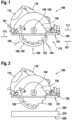
- FIG. 1 1 shows a hand-held power tool 100 embodied as a circular saw, for example, with a housing 110 which preferably forms a handle 112 .
- the circular saw 100 is a power unit (710 in 7 ) assigned, which is arranged at least in sections in the housing 110.
- the drive unit (710 in 7 ) serves to drive a tool holder 140 for an exchangeable saw blade 130.
- the saw blade 130 is preferably designed as a circular saw blade with a cutting edge 132 .
- the circular saw 100 is preferably mechanically and electrically connected to a power line 107 for mains-dependent power supply, but could be provided with a battery pack in addition or as an alternative to the mains-independent power supply.
- the circular saw 100 is designed in the manner of a hand-held circular saw and is therefore referred to below as the hand-held circular saw 100 .
- the hand-held circular saw 100 preferably its housing 110, preferably has a first and second end 111, 113, with the hand-held circular saw 100 being provided for sawing in a working direction 101.
- a corresponding working area 115 is preferably formed at the first end 111 or in front of the saw blade 130 in the working direction 101 .
- the hand-held circular saw 100 is preferably provided with a guide plate 120 which is mounted, for example, on an upper side (202 in 2 ) of a workpiece to be machined (210 in 2 ) is feasible.
- the guide plate 120 has an illustratively from the drive unit (710 in 7 ) facing away from underside 121, with which the portable circular saw 100, for example, on the top (202 in 2 ) of the workpiece to be machined (210 in 2 ) can be performed.
- a protective wedge 150 is associated with the saw blade 130 and is mounted in or on the housing 110 such that it can rotate about the associated axis of rotation 142 .
- the protective wedge 150 encloses the cutting edge 132 of the saw blade 130 at least during a sawing process in such a way that a user of the hand-held circular saw 100 is at least essentially prevented from touching the cutting edge 132 .
- the cutting edge 132 is illustratively completely surrounded by the protective wedge 150, so that the cutting edge 132 comes into contact in the region of the first end 111, the second end 113 and/or from a side facing, for example, the underside 121 of the guide plate 120, or illustratively in the direction of arrows 102, 103, 104.
- the protective wedge 150 is preferably rotatably mounted on the first end 111 or on the end 113 of the housing 110 facing away from the working area 115 .
- the protective wedge 150 is preferably designed in the manner of a semicircular ring 152 .
- the protective wedge 150 is preferably spring-loaded to enclose the cutting edge 132 of the saw blade 130 .
- the protective wedge 150 is preferably spring-loaded in such a way that the cutting edge 132 is surrounded to the maximum extent.
- the protective wedge 150 preferably has a thickness that corresponds at most to a thickness of the saw blade 130, so that the protective wedge 150 can be arranged or guided in a corresponding sawing groove formed by the saw blade 130 during a sawing process.
- the protective wedge 150 preferably releases the saw blade 130 by a maximum angular range of 90°. This preferably takes place during a sawing process with the maximum cutting depth of the saw blade 130.
- the hand-held circular saw 100 can preferably also have an optional protective pendulum hood.
- a corresponding pendulum protective hood is sufficiently known from the prior art, which is why a detailed description of the optional pendulum protective hood is dispensed with for the sake of simplicity and brevity of the description.
- FIG. 2 shows the hand-held circular saw 100 from 1 with the guard 150 in an open position in which the guard 150 only partially encloses the saw blade 130. Illustrated by example 2 a position that preferably corresponds to a maximum open or retracted position of the protective wedge 150 is equivalent to. However, it is pointed out that, depending on the application, the maximum open position of the protective wedge 150 can also release a larger area of the saw blade 130, for example in the case of a plunge saw, in which the protective wedge 150 can advantageously be screwed in completely.
- Illustrative is in 2 the hand-held circular saw 100 is arranged outside of a workpiece 210 .
- the workpiece 210 is in 2 embodied, for example, in a rectangular shape and has an upper and lower side 202, 201, with the hand-held circular saw 100 being arranged above the upper side 202 in an illustrative manner.
- Such an arrangement of the hand-held circular saw 100 above the workpiece 210 can be present, for example, before or after a sawing process or during a sawing process after a so-called "kickback" in which the hand-held circular saw 100 is catapulted out of the workpiece 210 .
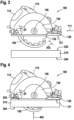
- FIG. 3 shows the hand-held circular saw 100 from 2 , In which the cutting edge 132 of the saw blade 130 by the spring-loaded protective wedge 150 compared to 2 is enclosed in a larger angular range or is almost completely enclosed.
- the cutting edge is 132 in 3 in a region 302 facing the first end 111 only remains free in an angular range of approximately 25°. Since the spring-loaded protective wedge 150 preferably has a comparatively small mass inertia, a comparatively rapid enclosing of the cutting edge 132 can thus be made possible.
- FIG. 4 shows the hand-held circular saw 100 from Figures 1 to 3 in a preferred working position during a sawing process in the workpiece 210, in which the guide plate 120 rests with its underside 121 on the upper side 202 of the workpiece 210 and is guided.
- the protective wedge 150 encloses the cutting edge 132 of the saw blade 130 in such a way that a user is effectively prevented from touching the saw blade 130 or the cutting edge 132 in the area of the underside 204 of the workpiece 210 or in the direction of an arrow 402 .
- figure 5 shows the hand-held circular saw 100 from 4 in the working position, in which, for example, there is an impact from the first end 111 in the direction of the second end 113 or an impact on the protective wedge 150 into the housing 110 or in the direction of an arrow 502 .
- Such action can be exerted, for example, by a part of a user's body, for example his hand.
- a contact sensor system 510 is assigned to the protective wedge 150 to protect a user in the event of such an impact.
- the touch sensor system 510 is arranged in the housing 110, but can also be arranged directly on the protective wedge 150 or any other point on the hand-held circular saw 100.
- Contact sensor system 510 preferably detects contact between protective wedge 150 and another object, for example the hand of a user of portable circular saw 100.
- contact sensor system 510 can also detect protective wedge 150 with a protective device specially designed for this purpose, e.g. one from contact sensor system 510 detectable glove or similar.
- the touch sensor system 510 is preferably designed to trigger a mechanism upon detection, which preferably blocks the protective wedge 150 .
- FIG. 6 shows the hand-held circular saw 100 from Figures 1 to 5 in the working position at a maximum cutting depth. This makes it clear 6 a cutting line 610 of the saw blade 130 in the workpiece 210.
- the protective wedge 150 is preferably arranged in its preferably maximum open position at maximum cutting depth, or preferably released by an angle ⁇ of preferably a maximum of 90°. As described above, the maximum open position of the protective wedge 150 can also be less than or greater than 90°.
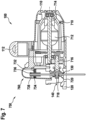
- FIG. 7 shows the exemplary hand-held circular saw 100 from FIG Figures 1 to 6 and illustrates a drive unit 710 of the hand-held circular saw 100.
- the drive unit 710 is preferably assigned a drive motor 712 with a drive shaft 716.
- the drive shaft 714 is designed to drive an output shaft 716 assigned to the tool holder 140 .
- the saw blade 130 is illustratively arranged on the tool holder 140 with a fastening means 718, preferably in a detachable manner.
- Fastening means 718 is preferably designed as a screw.
- the hand-held circular saw 100 has a safety device 750 which is designed to enable safe operation of the hand-held circular saw 100 .
- the security device 750 is preferably the touch sensor 510 of figure 5 assigned, with the touch sensors 510 in this case is preferably designed to activate the safety device 750 when contact is detected, for example by a body part of a user of the hand-held circular saw 100 .
- the security device 750 does not necessarily correspond to the touch sensor system 510 of FIG figure 5 must be assigned.
- the safety device 750 can also be assigned a separate contact sensor system, which can be arranged or assigned to the saw blade 130, for example.
- each of the embodiments of the security device 750 described below may be used separately or in combination with one or more other embodiments of the security device 750 .
- the safety device 750 acc. 7 preferably has a brake 760 designed as a saw blade brake for braking the saw blade 130, which is preferably triggered when the safety device 750 is activated.
- the saw blade brake 760 is preferably designed in the manner of a disk brake with at least one, illustratively two, brake disks 736, 738.
- the two brake discs 736, 738 are arranged to the side of saw blade 130, for example, with brake disc 736 in 7 is illustratively arranged to the right of the saw blade 130 and the brake disc 738 is illustratively arranged to the left of the saw blade 130.
- the two brake discs 736, 738 are preferably spring-loaded in each case via a spring element 732, 734.
- a mechanism is preferably provided which is designed to hold back the brake discs 736, 738 and/or the spring elements 732, 734 during a sawing process, so that the saw blade 130 can rotate unhindered or unbraked.
- the mechanism and/or spring members 732, 734 preferably include a hook member for retaining the brake discs 736, 738.
- the design of the mechanism for releasing the saw blade brake 760 is only of an exemplary nature and not is to be seen as a limitation of the present invention.
- the mechanism can be designed in different ways, for example as a combination with a spring element and a fuse wire.
- the spring element can be held back during a sawing process by a wire, which is burned through when contact is detected.
- the fusible wire can also be designed in the manner of a wire made from a shape memory alloy.
- the present invention is not limited to a saw blade brake 760 that acts directly on the saw blade 130.
- a braking element e.g. a brake disc
- the saw blade brake 760 is preferably arranged as far as possible at the end of the drive unit 710 so that as few rotating parts as possible have to be braked in order to bring the saw blade 130 to a standstill. As a result, a braking time of the saw blade 130 can be shortened.
- the brake 760 can alternatively also be designed as a wrap spring brake and/or wedge brake.
- a wedge brake has at least one wedge that brakes the saw blade 130 .
- self-reinforcement can be achieved by the at least one wedge and a rotational movement of the saw blade 130 .
- a comparatively high braking force can be achieved with a comparatively small spring force.
- the brake can also be designed as an exchangeable module, which allows easy handling of the saw blade brake 760.
- a wedge brake that jams at a comparatively high force, with the at least one wedge jamming between the saw blade 130 and a guide of the wedge can be easily and easily replaced and preferably reset or unjammed from the outside.
- the safety device 750 preferably has a coupling 720 for decoupling the drive unit 710 from the saw blade 130, so that only the saw blade 130 has to be braked.
- the saw blade brake 760 preferably only has to work against a relatively low torque of the drive motor 712 and only has to apply a moment to overcome the mass inertia of the hand-held circular saw 100 in order to brake the hand-held circular saw 100 or the saw blade 130 . This allows a comparatively short Braking time can be realized.
- the coupling 720 is preferably assigned to the tool holder 140 so that only the torque required for normal operation or for a sawing process is transmitted to the saw blade 130 .
- the clutch 720 can also be designed as a separate clutch, which is preferably arranged in the area of the saw blade 130 .
- the separate clutch is preferably designed analogously to the clutch 720 to decouple the saw blade 130 from the drive unit 710 .
- a relevant mass inertia to be braked should preferably be reduced in such a way that preferably as few parts as possible, particularly preferably only the saw blade 130, can be braked as quickly as possible.
- the security device 750 of the touch sensor system 510 is preferably of FIG figure 5 assigned, wherein the touch sensor 510 is preferably configured to activate the safety device 750 upon detection of a touch, for example by a body part of a user of the hand-held circular saw 100 .
- the safety device 750 activates the linear actuator 810, which is designed to move or displace the saw blade 130 linearly.
- the linear actuator 810 has a clutch 820 for decoupling the drive unit 710 from 7 is formed by the saw blade 130.
- clutch 820 is released, saw blade 130 being decoupled from drive unit 710 and linear actuator 810 linearly loading or displacing saw blade 130 preferably into housing 110 of hand-held circular saw 100 .
- the clutch 820 is preferably arranged between the output shaft 716 and an intermediate shaft 830 .
- the clutch 820 is preferably spring-loaded via at least one spring element 825 against the intermediate shaft 830.
- a torque and a rotational speed are preferably transmitted from the output shaft 716 via the clutch 820 to the intermediate shaft 830 and through the intermediate shaft 830 to the saw blade 130 .
- the intermediate shaft 830 is preferably mounted in a bearing housing 850.
- the clutch 820 preferably has a cylindrical base body 822 which, for example, has a through opening 829 for arrangement on the output shaft 716 and/or the intermediate shaft 830.
- the base body 822 On its side facing the intermediate shaft 830, the base body 822 preferably has a coupling section 827.
- the coupling section 827 is designed as a bevel.
- the clutch 820 is preferably decoupled first.
- a triggering element 840 acted upon by at least one spring element 849 is preferably released.
- the triggering element 840 is acted upon by the spring element 849 in an upward direction.
- the spring element 849 is preferably arranged on the guide plate 120 of the hand-held circular saw 100 .
- a surface 845 corresponding to the coupling section 827 is preferably assigned to the triggering element 840 . Due to the illustratively vertical movement of the triggering element 840, the surface 845 preferably presses the clutch 820 against the at least one spring element 825 or, illustratively, to the left.
- the clutch 820 is thus decoupled and the output shaft 716 is separated from the intermediate shaft 830 .
- an upper edge 842 of the triggering element 840 facing the bearing housing 850 preferably acts on the bearing housing 850 with the intermediate shaft 830 illustratively upwards or linearly upwards.
- FIG. 9 shows the hand-held circular saw 100 from 8 with the 810 linear actuator 9 the linear actuator system 810, which is preferably assigned two guide rails 922, 924, on which the triggering element 840 is arranged so that it can move linearly.
- the two guide rails 922, 924 are preferably arranged on the housing 110.
- the bearing housing 850 preferably has two lateral guide elements 912, 914, which are preferably mounted on the guide rails 922, 924.
- clarified 9 triggering element 840 which is acted upon by at least one spring element, illustratively by two spring elements 849, and which is designed to linearly act on or displace bearing housing 850 when clutch 820 is decoupled.
- the brake 1060 shows an alternative brake 1060 assigned to the safety device 750.
- the brake 1060 is preferably designed as a saw blade brake, with the saw blade brake 1060 preferably being designed in the manner of a pyro brake with a pyro 1040 and a blocking element 1042.
- the saw blade 130 preferably has a plurality 1030 of recesses 132, 134 in the circumferential direction, into which the blocking element 1042 is abruptly moved in the direction of an arrow 1002 when the safety device 750 or the pyrobrake 1060 is activated.
- the blocking element 1042 can also be acted upon by a spring element, or by a combination of a spring element and the pyro 1040.
Landscapes
- Life Sciences & Earth Sciences (AREA)
- Engineering & Computer Science (AREA)
- Mechanical Engineering (AREA)
- Wood Science & Technology (AREA)
- Forests & Forestry (AREA)
- Sawing (AREA)
Description
- Die vorliegende Erfindung betrifft eine Handkreissäge, gemäß dem Oberbegriff des Patentanspruchs 1, mit einem Gehäuse und einer zumindest abschnittsweise in dem Gehäuse angeordneten Antriebseinheit, der eine Werkzeugaufnahme für ein austauschbares Sägeblatt zugeordnet ist, wobei die Antriebseinheit zum drehenden Antrieb des austauschbaren Sägeblatts um eine zugeordnete Drehachse ausgebildet ist. Eine derartige Handkreissäge geht beispielsweise aus der
EP 0 012 404 A1 hervor. - Aus dem Stand der Technik ist eine derartige, als Handkreissäge ausgebildete Kreissäge bekannt, die ein Gehäuse und eine abschnittsweise in dem Gehäuse angeordnete Antriebseinheit aufweist. Dabei ist der Antriebseinheit eine Werkzeugaufnahme für ein austauschbares Sägeblatt zugeordnet und die Antriebseinheit ist zum drehenden Antrieb des austauschbaren Sägeblatts um eine zugeordnete Drehachse ausgebildet. Zum Schutz eines Benutzers der Kreissäge vor einer Verletzung aufgrund einer Berührung der Schneide, weist die Kreissäge eine Pendelschutzhaube auf. Diese Pendelschutzhaube umschließt das Sägeblatt und ist drehbar um einen Sägeblattmittelpunkt gelagert. Bei einem Sägevorgang wird die Pendelschutzhaube in das Gehäuse der Kreissäge beaufschlagt, sodass das Sägeblatt freiliegt und so eine Verletzung aufgrund einer Berührung des Benutzers mit der Schneide entstehen kann.
- Die vorliegende Erfindung stellt eine Kreissäge, insbesondere eine Handkreissäge, mit einem Gehäuse und einer zumindest abschnittsweise in dem Gehäuse angeordneten Antriebseinheit bereit, der eine Werkzeugaufnahme für ein austauschbares Sägeblatt zugeordnet ist. Die Antriebseinheit ist zum drehenden Antrieb des austauschbaren Sägeblatts um eine zugeordnete Drehachse ausgebildet. Dem austauschbaren Sägeblatt ist ein Schutzkeil zugeordnet, der um die zugeordnete Drehachse drehbar im Gehäuse gelagert ist und eine Schneide des austauschbaren Sägeblatts zumindest während eines Sägevorgangs derart umschließt, dass eine Berührung der Schneide zumindest im Wesentlichen verhindert werden kann.
- Die Erfindung ermöglicht somit die Bereitstellung einer Kreissäge, insbesondere einer Handkreissäge, bei der durch den Schutzkeil auch bei einem Sägevorgang ein entsprechendes Verletzungsrisiko aufgrund einer Berührung mit der Schneide des Sägeblatts zumindest weitgehend reduziert werden kann. Somit kann die Bereitstellung einer sicheren und zuverlässigen Kreissäge ermöglicht werden.
- Der Schutzkeil weist bevorzugt eine Dicke auf, die maximal einer Dicke des austauschbaren Sägeblatts entspricht. Somit kann der Schutzkeil während eines Sägevorgangs in einer vom Sägeblatt ausgebildeten Sägenut geführt werden und somit das Sägeblatt auch während eines Sägevorgangs umschließen und hierdurch eine Berührung mit der Schneide des Sägeblatts zumindest annähernd verhindern.
- Vorzugsweise ist der Schutzkeil zum Umschließen der Schneide des austauschbaren Sägeblatts federbeaufschlagt. Somit kann eine Anordnung des Schutzkeils ermöglicht werden, bei der die Schneide des Sägeblatts immer maximal umschlossen werden kann.
- Gemäß einer Ausführungsform ist der Schutzkeil derart federbeaufschlagt, dass die Schneide des austauschbaren Sägeblatts maximal umschlossen wird. Somit kann eine Berührung mit der Schneide auch während eines Sägevorgangs sicher und zuverlässig zumindest im Wesentlichen verhindert werden.
- Bevorzugt ist der Schutzkeil an einem von einem Arbeitsbereich der Kreissäge abgewandten Ende des Gehäuses drehbar gelagert. Somit kann einfach und unkompliziert eine maximale Umschließung des Sägeblatts ermöglicht werden.
- Der Schutzkeil ist vorzugsweise nach Art eines Halbkreisrings ausgebildet. Somit kann auf einfache Art und Weise ein geeigneter Schutzkeil bereitgestellt werden, der schwenkbar um die Drehachse der Antriebseinheit anordenbar ist.
- Gemäß einer Ausführungsform gibt der Schutzkeil bei einem Sägevorgang das austauschbare Sägeblatt maximal in einem Winkelbereich von 90° frei. Somit kann bei maximaler Schnitttiefe eine maximale Umschließung des Sägeblatts ermöglicht werden.
- Dem Schutzkeil ist eine Berührungssensorik zugeordnet. Somit kann sicher und unkompliziert ein Berührungsschutz im Bereich eines Arbeitsbereichs der Kreissäge ermöglicht werden.
- Es ist eine Sicherheitsvorrichtung vorgesehen, die dazu ausgebildet ist, einen sicheren Betrieb der Kreissäge zu ermöglichen. Die Sicherheitsvorrichtung ist zusätzlich zu dem Schutzkeil vorgesehen. Somit kann auf einfache Art und Weise die Bereitstellung einer sicheren und zuverlässigen Kreissäge ermöglicht werden.
- Die Sicherheitsvorrichtung weist vorzugsweise eine Kupplung zum Entkoppeln der Antriebseinheit vom austauschbaren Sägeblatt auf. Somit können bei einer Detektion einer Berührung ein schnelles Abbremsen des Sägeblatts und eine vergleichsweise kurze Bremszeit ermöglicht werden.
- Die Sicherheitsvorrichtung weist bevorzugt eine Sägeblattbremse auf. Somit kann auf einfache Art und Weise ein Abbremsen des Sägeblatts bei einer Detektion einer Berührung ermöglicht werden.
- Vorzugsweise ist die Sägeblattbremse nach Art einer Scheibenbremse mit zumindest einer Bremsscheibe ausgebildet, oder nach Art einer Pyrobremse mit einem Pyro und einem Blockierelement. Somit kann einfach und unkompliziert eine geeignete Sägeblattbremse bereitgestellt werden.
- Gemäß einer Ausführungsform weist die Sicherheitsvorrichtung eine Linearaktorik zur linearen Verschiebung des austauschbaren Sägeblatts auf. Somit kann das Sägeblatt bei einer Detektion einer Berührung in das Gehäuse beaufschlagt werden, sodass die Berührung schnell unterbunden werden kann.
- Die Erfindung ist anhand von in den Zeichnungen dargestellten Ausführungsbeispielen in der nachfolgenden Beschreibung näher erläutert. Es zeigen:
- Fig. 1
- eine Seitenansicht einer Handwerkzeugmaschine mit einem Schutzkeil in einer Schutzposition,
- Fig. 2
- eine Seitenansicht der Handwerkzeugmaschine von
Fig. 1 mit dem Schutzkeil in einer maximal geöffneten Stellung, - Fig. 3
- eine Seitenansicht der Handwerkzeugmaschine von
Fig. 2 mit dem Schutzkeil in einer weitgehend geschlossenen Stellung, - Fig. 4
- eine Seitenansicht der Handwerkzeugmaschine von
Fig. 1 bis Fig. 3 bei einem Sägevorgang in einem Werkstück, - Fig. 5
- eine Seitenansicht der Handwerkzeugmaschine von
Fig. 4 bei einem Sägevorgang, mit einer Beaufschlagung des Schutzkeils, - Fig. 6
- eine Seitenansicht der Handwerkzeugmaschine von
Fig. 4 undFig. 5 bei einem Sägevorgang in einem Werkstück, mit dem Schutzkeil in einer maximal geöffneten Stellung, - Fig. 7
- eine Schnittansicht der Handwerkzeugmaschine von
Fig. 1 bis Fig. 6 mit einer Sägeblattbremse gemäß einer Ausführungsform, - Fig. 8
- eine Schnittansicht der Handwerkzeugmaschine von
Fig. 1 bis Fig. 7 mit einer Linearaktorik, - Fig. 9
- eine Schnittansicht der Handwerkzeugmaschine von
Fig. 1 bis Fig. 7 , mit der Linearaktorik vonFig. 8 , gesehen in Richtung von Pfeilen IX vonFig. 8 , und - Fig. 10
- eine perspektivische Ansicht einer der Handwerkzeugmaschine von
Fig. 1 bis Fig. 7 zugeordneten Sägeblattbremse gemäß einer weiteren Ausführungsform. -
Fig. 1 zeigt eine beispielhaft als Kreissäge ausgebildete Handwerkzeugmaschine 100 mit einem Gehäuse 110, das bevorzugt einen Handgriff 112 ausbildet. Der Kreissäge 100 ist eine Antriebseinheit (710 inFig. 7 ) zugeordnet, die zumindest abschnittsweise im Gehäuse 110 angeordnet ist. Die Antriebseinheit (710 inFig. 7 ) dient zum Antrieb einer Werkzeugaufnahme 140 für ein austauschbares Sägeblatt 130. Dabei ist die Antriebseinheit (710 inFig. 7 ) zum drehenden Antrieb des austauschbaren Sägeblatts 130 um eine zugeordnete Drehachse 142 ausgebildet. Das Sägeblatt 130 ist vorzugsweise als Kreissägeblatt mit einer Schneide 132 ausgebildet. - Bevorzugt ist die Kreissäge 100 zur netzabhängigen Stromversorgung mechanisch und elektrisch mit einer Stromleitung 107 verbunden, könnte jedoch zusätzlich oder alternativ zur netzunabhängigen Stromversorgung mit einem Akkupack versehen sein. Die Kreissäge 100 ist nach Art einer Handkreissäge ausgebildet und wird deshalb nachfolgend als die Handkreissäge 100 bezeichnet.
- Vorzugsweise weist die Handkreissäge 100, bevorzugt deren Gehäuse 110, ein erstes und zweites Ende 111, 113 auf, wobei die Handkreissäge 100 zum Sägen in eine Arbeitsrichtung 101 vorgesehen ist. Dabei ist bevorzugt ein entsprechender Arbeitsbereich 115 am ersten Ende 111 bzw. in Arbeitsrichtung 101 vor dem Sägeblatt 130 ausgebildet. Darüber hinaus ist die Handkreissäge 100 vorzugsweise mit einer Führungsplatte 120 versehen, die z.B. auf einer Oberseite (202 in
Fig. 2 ) eines zu bearbeitenden Werkstücks (210 inFig. 2 ) führbar ist. Dabei weist die Führungsplatte 120 eine illustrativ von der Antriebseinheit (710 inFig. 7 ) abgewandte Unterseite 121 auf, mit der die Handkreissäge 100 z.B. auf der Oberseite (202 inFig. 2 ) des zu bearbeitenden Werkstücks (210 inFig. 2 ) geführt werden kann. - Dem Sägeblatt 130 ist ein Schutzkeil 150 zugeordnet, der um die zugeordnete Drehachse 142 drehbar im bzw. am Gehäuse 110 gelagert ist. Dabei umschließt der Schutzkeil 150 die Schneide 132 des Sägeblatts 130 zumindest während eines Sägevorgangs derart, dass eine Berührung der Schneide 132 durch einen Benutzer der Handkreissäge 100 zumindest im Wesentlichen verhindert wird. In
Fig. 1 ist die Schneide 132 illustrativ komplett vom Schutzkeil 150 umschlossen, sodass eine Berührung der Schneide 132 im Bereich des ersten Endes 111, des zweiten Endes 113 und/oder von einer beispielhaft der Unterseite 121 der Führungsplatte 120 zugewandten Seite, bzw. illustrativ in Richtung von Pfeilen 102, 103, 104, verhindert wird. - Vorzugsweise ist der Schutzkeil 150 am ersten Ende 111 bzw. an dem vom Arbeitsbereich 115 abgewandten Ende 113 des Gehäuses 110 drehbar gelagert. Bevorzugt ist der Schutzkeil 150 dabei nach Art eines Halbkreisrings 152 ausgebildet. Der Schutzkeil 150 ist vorzugsweise zum Umschließen der Schneide 132 des Sägeblatts 130 federbeaufschlagt. Bevorzugt ist der Schutzkeil 150 dabei derart federbeaufschlagt, dass die Schneide 132 maximal umschlossen wird. Hierbei weist der Schutzkeil 150 bevorzugt eine Dicke auf, die maximal einer Dicke des Sägeblatts 130 entspricht, sodass der Schutzkeil 150 bei einem Sägevorgang in einer entsprechenden, vom Sägeblatt 130 ausgebildeten Sägenut anordenbar bzw. führbar ist. Bei einem Sägevorgang gibt der Schutzkeil 150 das Sägeblatt 130 bevorzugt maximal um einen Winkelbereich von 90° frei. Dies erfolgt vorzugsweise bei einem Sägevorgang mit maximaler Schnitttiefe des Sägeblatts 130.
- Darüber hinaus kann die Handkreissäge 100 vorzugsweise auch eine optionale Pendelschutzhaube aufweisen. Eine entsprechende Pendelschutzhaube ist aus dem Stand der Technik hinreichend bekannt, weshalb zwecks Einfachheit und Knappheit der Beschreibung auf eine eingehende Beschreibung der optionalen Pendelschutzhaube verzichtet wird.
-
Fig. 2 zeigt die Handkreissäge 100 vonFig. 1 mit dem Schutzkeil 150 in einer geöffneten Stellung, bei der der Schutzkeil 150 das Sägeblatt 130 nur teilweise umschließt. Beispielhaft verdeutlichtFig. 2 hierbei eine Stellung, die bevorzugt einer maximal geöffneten bzw. zurückgefahrenenStellung des Schutzkeils 150 entspricht. Es wird jedoch darauf hingewiesen, dass anwendungsspezifisch die maximal geöffnete Stellung des Schutzkeils 150 auch einen größeren Bereich des Sägeblatts 130 freigeben kann, z.B. bei einer Tauchsäge, bei der vorteilhafterweise der Schutzkeil 150 komplett eingedreht werden kann. - Illustrativ ist in
Fig. 2 die Handkreissäge 100 außerhalb eines Werkstücks 210 angeordnet. Das Werkstück 210 ist inFig. 2 beispielsweise rechteckförmig ausgebildet und weist eine Ober- und Unterseite 202, 201 auf, wobei die Handkreissäge 100 illustrativ oberhalb der Oberseite 202 angeordnet ist. Eine derartige Anordnung der Handkreissäge 100 oberhalb des Werkstücks 210 kann beispielsweise vor oder nach einem Sägevorgang oder während eines Sägevorgangs nach einem sogenannten "Kickback", bei dem die Handkreissäge 100 aus dem Werkstück 210 herauskatapultiert wird, vorliegen. -
Fig. 3 zeigt die Handkreissäge 100 vonFig. 2 , bei der durch den federbeaufschlagten Schutzkeil 150 die Schneide 132 des Sägeblatts 130 im Vergleich zuFig. 2 in einem größeren Winkelbereich umschlossen ist bzw. fast vollständig umschlossen ist. Dabei ist die Schneide 132 inFig. 3 in einem dem ersten Ende 111 zugewandten Bereich 302 nur noch in einem Winkelbereich von ungefähr um 25° frei. Da der federbeaufschlagte Schutzkeil 150 bevorzugt eine vergleichsweise kleine Massenträgheit aufweist, kann so ein vergleichsweise schnelles Umschließen der Schneide 132 ermöglicht werden. -
Fig. 4 zeigt die Handkreissäge 100 vonFig. 1 bis Fig. 3 in einer bevorzugten Arbeitsstellung bei einem Sägevorgang im Werkstück 210, in der die Führungsplatte 120 mit ihrer Unterseite 121 auf der Oberseite 202 des Werkstücks 210 aufliegt und geführt ist. Dabei umschließt der Schutzkeil 150 die Schneide 132 des Sägeblatts 130 derart, dass eine Berührung eines Benutzers mit dem Sägeblatt 130 bzw. der Schneide 132 im Bereich der Unterseite 204 des Werkstücks 210 bzw. in Richtung eines Pfeils 402 wirksam verhindert wird. -
Fig. 5 zeigt die Handkreissäge 100 vonFig. 4 in der Arbeitsstellung, bei der beispielhaft eine Beaufschlagung vom ersten Ende 111 in Richtung des zweiten Endes 113 bzw. eine Beaufschlagung des Schutzkeils 150 ins Gehäuse 110 bzw. in Richtung eines Pfeils 502 erfolgt. Eine derartige Beaufschlagung kann beispielsweise von einem Körperteil eines Benutzers, z.B. dessen Hand, ausgeübt werden. Zum Schutz eines Benutzers bei einer derartigen Beaufschlagung ist dem Schutzkeil 150 eine Berührungssensorik 510 zugeordnet. - Illustrativ ist in
Fig. 5 die Berührungssensorik 510 im Gehäuse 110 angeordnet, kann jedoch auch direkt am Schutzkeil 150 oder einer beliebig anderen Stelle der Handkreissäge 100 angeordnet sein. Vorzugsweise detektiert die Berührungssensorik 510 einen Kontakt zwischen dem Schutzkeil 150 und einem anderen Objekt, beispielsweise der Hand eines Benutzers der Handkreissäge 100. Darüber hinaus kann die Berührungssensorik 510 auch eine Detektion des Schutzkeils 150 mit einer speziell hierzu ausgebildeten Schutzvorrichtung, z.B. einem von der Berührungssensorik 510 detektierbaren Handschuh oder ähnlichem, erfassen. Dabei ist die Berührungssensorik 510 bevorzugt dazu ausgebildet, bei einer Detektion einen Mechanismus auszulösen, der vorzugsweise den Schutzkeil 150 blockiert. -
Fig. 6 zeigt die Handkreissäge 100 vonFig. 1 bis Fig. 5 in der Arbeitsstellung bei einer maximalen Schnitttiefe. Dabei verdeutlichtFig. 6 eine Schnittlinie 610 des Sägeblatts 130 im Werkstück 210. Vorzugsweise ist der Schutzkeil 150 bei maximaler Schnitttiefe in seiner bevorzugt maximal geöffneten Stellung angeordnet, bzw. vorzugsweise um einen Winkel α von vorzugsweise maximal 90° freigegeben. Wie oben beschrieben, kann die maximal geöffnete Stellung des Schutzkeils 150 auch kleiner oder größer als 90° sein. -
Fig. 7 zeigt die beispielhafte Handkreissäge 100 vonFig. 1 bis Fig. 6 und verdeutlicht eine Antriebseinheit 710 der Handkreissäge 100. Der Antriebseinheit 710 ist vorzugsweise ein Antriebsmotor 712 mit einer Antriebswelle 716 zugeordnet. Die Antriebswelle 714 ist dabei zum Antrieb einer der Werkzeugaufnahme 140 zugeordneten Abtriebswelle 716 ausgebildet. Das Sägeblatt 130 ist dabei illustrativ mit einem Befestigungsmittel 718 bevorzugt lösbar an der Werkzeugaufnahme 140 angeordnet. Vorzugsweise ist das Befestigungsmittel 718 als Schraube ausgebildet. - Die Handkreissäge 100 weist eine Sicherheitsvorrichtung 750 auf, die dazu ausgebildet ist, einen sicheren Betrieb der Handkreissäge 100 zu ermöglichen. Die Sicherheitsvorrichtung 750 ist bevorzugt der Berührungssensorik 510 von
Fig. 5 zugeordnet, wobei die Berührungssensorik 510 in diesem Fall vorzugsweise dazu ausgebildet ist, bei einer Detektion einer Berührung, z.B. durch ein Körperteil eines Benutzers der Handkreissäge 100, die Sicherheitsvorrichtung 750 zu aktivieren. - Es wird jedoch darauf hingewiesen, dass die Sicherheitsvorrichtung 750 nicht zwingend der Berührungssensorik 510 von
Fig. 5 zugeordnet sein muss. Darüber hinaus kann der Sicherheitsvorrichtung 750 auch eine separate Berührungssensorik zugeordnet sein, die z.B. am Sägeblatt 130 angeordnet bzw. diesem zugeordnet sein kann. Analog hierzu kann jede der nachfolgend beschriebenen Ausführungsformen der Sicherheitsvorrichtung 750 separat oder in Kombination mit einer oder mehreren anderen Ausführungsformen der Sicherheitsvorrichtung 750 Anwendung finden. - Die Sicherheitsvorrichtung 750 gem.
Fig. 7 weist vorzugsweise eine als Sägeblattbremse ausgebildete Bremse 760 zum Abbremsen des Sägeblatts 130 auf, die bevorzugt bei einer Aktivierung der Sicherheitsvorrichtung 750 ausgelöst wird. Dabei ist die Sägeblattbremse 760 bevorzugt nach Art einer Scheibenbremse mit zumindest einer, illustrativ zwei Bremsscheiben 736, 738 ausgebildet. Hierbei sind die beiden Bremsscheiben 736, 738 beispielhaft seitlich des Sägeblatts 130 angeordnet, wobei die Bremsscheibe 736 inFig. 7 illustrativ rechts vom Sägeblatt 130 angeordnet ist und die Bremsscheibe 738 illustrativ links vom Sägeblatt 130 angeordnet ist. Vorzugsweise sind die beiden Bremsscheiben 736, 738 jeweils über ein Federelement 732, 734 federbeaufschlagt. Hierbei ist bevorzugt ein Mechanismus vorgesehen, der dazu ausgebildet ist, die Bremsscheiben 736, 738 und/oder die Federelemente 732, 734 bei einem Sägevorgang zurück zu halten, sodass das Sägeblatt 130 ungehindert bzw. ungebremst drehen kann. Der Mechanismus und/oder die Federelemente 732, 734 weisen zum Zurückhalten der Bremsscheiben 736, 738 vorzugsweise ein Hakenelement auf. Bei einer Auslösung der Sägeblattbremse 760 durch die Berührungssensorik 510, bzw. bei einer Berührung, gibt bevorzugt ein Aktuator das Hakenelement frei und die Federelemente 732, 734 beaufschlagen die Bremsscheiben 736, 738 auf das Sägeblatt 130. - Es wird darauf hingewiesen, dass die Ausgestaltung des Mechanismus zum Auslösen der Sägeblattbremse 760 lediglich beispielhaften Charakter hat und nicht als Einschränkung der vorliegenden Erfindung zu sehen ist. So kann der Mechanismus auf unterschiedliche Art und Weise ausgebildet sein, z.B. als eine Kombination mit einem Federelement und einem Schmelzdraht. Dabei kann beispielhaft das Federelement bei einem Sägevorgang durch einen Draht zurückgehalten werden, welche bei einer Detektion einer Berührung durchgebrannt wird. Alternative hierzu kann der Schmelzdraht auch nach Art eines Drahtes aus einer Formgedächtnislegierung ausgebildet sein.
- Jedoch ist die vorliegende Erfindung nicht auf eine Sägeblattbremse 760, die direkt am Sägeblatt 130 angreift, beschränkt. So kann beispielhaft auch ein Bremselement, z.B. eine Bremsscheibe, unmittelbar an der Werkzeugaufnahme 140 angreifen. Bevorzugt ist die Sägeblattbremse 760 möglichst weit am Ende der Antriebseinheit 710 angeordnet, sodass möglichst wenig drehende Teile abgebremst werden müssen, um das Sägeblatt 130 zum Stehen zu bringen. Dadurch kann eine Bremszeit des Sägeblatts 130 verkürzt werden.
- Darüber hinaus kann die Bremse 760 alternativ auch als Schlingfederbremse und/oder Keilbremse ausgebildet sein. Dabei weist eine Keilbremse zumindest einen Keil auf, der das Sägeblatt 130 abbremst. Hierbei kann eine Selbstverstärkung durch den zumindest einen Keil und eine Rotationsbewegung des Sägeblatts 130 erreicht werden. Dadurch kann eine vergleichsweise hohe Bremskraft mit einer vergleichsweise kleinen Federkraft erreicht werden. Vorzugsweise kann die Bremse auch als austauschbares Modul ausgebildet sein, wodurch ein einfaches Handling der Sägeblattbremse 760 ermöglicht werden kann. So kann beispielsweise eine Keilbremse, die bei einer vergleichsweise hohen Kraft verklemmt, wobei sich der zumindest eine Keil zwischen dem Sägeblatt 130 und einer Führung des Keils verklemmt, einfach und unkompliziert ausgetauscht werden und vorzugsweise von extern aus zurückgesetzt bzw. entklemmt werden.
- Des Weiteren weist die Sicherheitsvorrichtung 750 bevorzugt eine Kupplung 720 zum Entkoppeln der Antriebseinheit 710 vom Sägeblatt 130 auf, sodass lediglich das Sägeblatt 130 abgebremst werden muss. Somit muss die Sägeblattbremse 760 vorzugsweise nur gegen ein verhältnismäßig geringes Drehmoment des Antriebsmotors 712 arbeiten und muss lediglich ein Moment zum Überwinden der Massenträgheit der Handkreissäge 100 aufbringen, um die Handkreissäge 100 bzw. das Sägeblatt 130 abzubremsen. Dadurch kann eine vergleichsweise kurze Bremszeit verwirklicht werden. Bevorzugt ist die Kupplung 720 der Werkzeugaufnahme 140 zugeordnet, sodass nur ein notwendiges Moment für einen Normalbetrieb bzw. für einen Sägevorgang auf das Sägeblatt 130 übertragen wird.
- Es wird jedoch darauf hingewiesen, dass die Ausgestaltung der Werkzeugaufnahme 140 mit der Kupplung 720 lediglich beispielhaften Charakter hat und nicht als Einschränkung der Erfindung zu sehen ist. So kann die Kupplung 720 auch als separate Kupplung ausgebildet sein, die vorzugsweise im Bereich des Sägeblatts 130 angeordnet ist. Dabei ist die separate Kupplung bevorzugt analog zur Kupplung 720 dazu ausgebildet, das Sägeblatt 130 von der Antriebseinheit 710 zu entkoppeln. Bevorzugt soll eine relevante abzubremsende Massenträgheit derart verringert werden, sodass vorzugsweise so wenig Teile wie möglich, besonders bevorzugt lediglich das Sägeblatt 130, schnellstmöglich abgebremst werden können.
-
Fig. 8 zeigt die Handkreissäge 100 vonFig. 1 bis Fig. 7 mit der Sicherheitsvorrichtung 750, der alternativ oder zusätzlich eine Linearaktorik 810 zugeordnet ist. Wie oben beschrieben, ist bevorzugt die Sicherheitsvorrichtung 750 der Berührungssensorik 510 vonFig. 5 zugeordnet, wobei die Berührungssensorik 510 vorzugsweise dazu ausgebildet ist, bei einer Detektion einer Berührung, z.B. durch ein Körperteil eines Benutzers der Handkreissäge 100, die Sicherheitsvorrichtung 750 zu aktivieren. Dabei aktiviert die Sicherheitsvorrichtung 750 die Linearaktorik 810, die dazu ausgebildet ist, das Sägeblatt 130 linear zu bewegen bzw. zu verschieben. - Vorzugsweise weist die Linearaktorik 810 eine Kupplung 820 auf, die zum Entkoppeln der Antriebseinheit 710 von
Fig. 7 vom Sägeblatt 130 ausgebildet ist. Bei einer Aktivierung der Sicherheitsvorrichtung 750 wird die Kupplung 820 freigegeben, wobei das Sägeblatt 130 von der Antriebseinheit 710 entkoppelt wird und wobei die Linearaktorik 810 das Sägeblatt 130 linear bevorzugt in das Gehäuse 110 der Handkreissäge 100 hinein beaufschlagt bzw. verschiebt. Somit wird insbesondere im Fall einer Berührung durch ein Körperteil eines Benutzers der Handkreissäge 100 ein entsprechender Kontakt sehr schnell aufgehoben, sodass maximal nur vergleichsweise geringe Einschnitte bzw. Verletzungen am Körperteil entstehen können. - Die Kupplung 820 ist vorzugsweise zwischen der Abtriebswelle 716 und einer Zwischenwelle 830 angeordnet. Bei einem Sägevorgang ist die Kupplung 820 bevorzugt über zumindest ein Federelement 825 gegen die Zwischenwelle 830 federbeaufschlagt. Dabei werden ein Drehmoment und eine Drehzahl von der Abtriebswelle 716 bevorzugt über die Kupplung 820 auf die Zwischenwelle 830 und durch die Zwischenwelle 830 auf das Sägeblatt 130 übertragen. Die Zwischenwelle 830 ist vorzugsweise in einem Lagergehäuse 850 gelagert.
- Vorzugsweise weist die Kupplung 820 einen zylindrischen Grundkörper 822 auf, der beispielhaft eine Durchgangsöffnung 829 zur Anordnung auf der Abtriebswelle 716 und/oder der Zwischenwelle 830 aufweist. An seiner der Zwischenwelle 830 zugewandten Seite weist der Grundkörper 822 bevorzugt einen Kupplungsabschnitt 827 auf. Illustrativ und beispielhaft ist der Kupplungsabschnitt 827 als Schräge ausgebildet.
- Bei einer Aktivierung der Sicherheitsvorrichtung 750 wird bevorzugt zuerst die Kupplung 820 entkoppelt. Dabei wird vorzugsweise ein durch zumindest ein Federelement 849 beaufschlagtes Auslöseelement 840 freigegeben. Durch das Federelement 849 wird das Auslöseelement 840 illustrativ nach oben beaufschlagt. Vorzugsweise ist das Federelement 849 an der Führungsplatte 120 der Handkreissäge 100 angeordnet. Dem Auslöseelement 840 ist bevorzugt eine mit dem Kupplungsabschnitt 827 korrespondierende Fläche 845 zugeordnet. Durch die illustrativ vertikale Bewegung des Auslöseelements 840 drückt die Fläche 845 die Kupplung 820 vorzugsweise gegen das zumindest eine Federelement 825 bzw. illustrativ nach links. Somit wird die Kupplung 820 entkoppelt und die Abtriebswelle 716 von der Zwischenwelle 830 getrennt. Dabei beaufschlagt eine dem Lagergehäuse 850 zugewandte Oberkante 842 des Auslöseelements 840 vorzugsweise das Lagergehäuse 850 mit der Zwischenwelle 830 illustrativ nach oben bzw. linear nach oben.
-
Fig. 9 zeigt die Handkreissäge 100 vonFig. 8 mit der Linearaktorik 810. Dabei verdeutlichFig. 9 die Linearaktorik 810, der bevorzugt zwei Führungsschienen 922, 924 zugeordnet sind, an denen das Auslöseelement 840 linear bewegbar angeordnet ist. Vorzugsweise sind die zwei Führungsschienen 922, 924 am Gehäuse 110 angeordnet. Zur linearen Bewegung der Zwischenwelle 830 weist das Lagergehäuse 850 vorzugsweise zwei seitliche Führungselemente 912, 914 auf, die bevorzugt an den Führungsschienen 922, 924 gelagert sind. Darüber hinaus verdeutlichtFig. 9 das über zumindest ein Federelement, illustrativ über zwei Federelemente 849, beaufschlagte Auslöseelement 840, das dazu ausgebildet ist, das Lagergehäuse 850 bei entkoppelter Kupplung 820 linear zu beaufschlagen bzw. zu verschieben. -
Fig. 10 zeigt eine alternative, der Sicherheitsvorrichtung 750 zugeordnet Bremse 1060. Die Bremse 1060 ist vorzugsweise als Sägeblattbremse ausgebildet, wobei die Sägeblattbremse 1060 bevorzugt nach Art einer Pyrobremse mit einem Pyro 1040 und einem Blockierelement 1042 ausgebildet ist. Hierfür weist das Sägeblatt 130 in Umfangsrichtung vorzugsweise eine Mehrzahl 1030 von Ausnehmungen 132, 134 auf, in die bei einer Aktivierung der Sicherheitsvorrichtung 750 bzw. der Pyrobremse 1060 das Blockierelement 1042 in Richtung eines Pfeils 1002 schlagartig bewegt wird. Dabei kann das Blockierelement 1042 auch durch ein Federelement beaufschlagt werden, oder von einer Kombination aus einem Federelement und dem Pyro 1040.
Claims (11)
- Handkreissäge (100) mit einem Gehäuse (110) und einer zumindest abschnittsweise in dem Gehäuse (110) angeordneten Antriebseinheit (710), der eine Werkzeugaufnahme (140) für ein austauschbares Sägeblatt (130) zugeordnet ist, wobei die Antriebseinheit (710) zum drehenden Antrieb des austauschbaren Sägeblatts (130) um eine zugeordnete Drehachse (142) ausgebildet ist, wobei dem austauschbaren Sägeblatt (130) ein Schutzkeil (150) zugeordnet ist, der um die zugeordnete Drehachse (142) drehbar im Gehäuse (110) gelagert ist und eine Schneide (132) des austauschbaren Sägeblatts (130) zumindest während eines Sägevorgangs derart umschließt, dass eine Berührung der Schneide (132) zumindest im Wesentlichen verhindert werden kann, dadurch gekennzeichnet, dass dem Schutzkeil (150) eine Berührungssensorik (510) zugeordnet ist und dass eine Sicherheitsvorrichtung (750) vorgesehen ist, die dazu ausgebildet ist, einen sicheren Betrieb der Handkreissäge (100) zu ermöglichen.
- Handkreissäge (100) nach Anspruch 1, dadurch gekennzeichnet, dass der Schutzkeil (150) eine Dicke aufweist, die maximal einer Dicke des austauschbaren Sägeblatts (130) entspricht.
- Handkreissäge (100) nach Anspruch 1 oder 2, dadurch gekennzeichnet, dass der Schutzkeil (150) zum Umschließen der Schneide (132) des austauschbaren Sägeblatts (130) federbeaufschlagt ist.
- Handkreissäge (100) nach Anspruch 3, dadurch gekennzeichnet, dass der Schutzkeil (150) derart federbeaufschlagt ist, dass die Schneide (132) des austauschbaren Sägeblatts (130) maximal umschlossen wird.
- Handkreissäge (100) nach einem der vorhergehenden Ansprüche, dadurch gekennzeichnet, dass der Schutzkeil (150) an einem von einem Arbeitsbereich (115) der Handkreissäge (100) abgewandten Ende (113) des Gehäuses (110) drehbar gelagert ist.
- Handkreissäge (100) nach einem der vorhergehenden Ansprüche, dadurch gekennzeichnet, dass der Schutzkeil (150) nach Art eines Halbkreisrings (152) ausgebildet ist.
- Handkreissäge (100) nach einem der vorhergehenden Ansprüche, dadurch gekennzeichnet, dass der Schutzkeil (150) bei einem Sägevorgang das austauschbare Sägeblatt (130) maximal in einem Winkelbereich von 90° freigibt.
- Handkreissäge (100) nach Anspruch 1, dadurch gekennzeichnet, dass die Sicherheitsvorrichtung (750) eine Kupplung (720; 820) zum Entkoppeln der Antriebseinheit (710) vom austauschbaren Sägeblatt (130) aufweist.
- Handkreissäge (100) nach Anspruch 1 oder 8, dadurch gekennzeichnet, dass die Sicherheitsvorrichtung (750) eine Sägeblattbremse (760; 1060) aufweist.
- Handkreissäge (100) nach Anspruch 9, dadurch gekennzeichnet, dass die Sägeblattbremse (760; 1060) nach Art einer Scheibenbremse mit zumindest einer Bremsscheibe (736, 738) ausgebildet ist, oder nach Art einer Pyrobremse (1060) mit einem Pyro (1040) und einem Blockierelement (1042).
- Handkreissäge (100) nach einem der Ansprüche 8 bis 10, dadurch gekennzeichnet, dass die Sicherheitsvorrichtung (750) eine Linearaktorik (810) zur linearen Verschiebung des austauschbaren Sägeblatts (130) aufweist.
Applications Claiming Priority (2)
| Application Number | Priority Date | Filing Date | Title |
|---|---|---|---|
| DE102017201493.8A DE102017201493A1 (de) | 2017-01-31 | 2017-01-31 | Kreissäge, insbesondere Handkreissäge |
| PCT/EP2018/050494 WO2018141512A1 (de) | 2017-01-31 | 2018-01-10 | Kreissäge, insbesondere handkreissäge |
Publications (2)
| Publication Number | Publication Date |
|---|---|
| EP3576913A1 EP3576913A1 (de) | 2019-12-11 |
| EP3576913B1 true EP3576913B1 (de) | 2023-03-08 |
Family
ID=60953878
Family Applications (1)
| Application Number | Title | Priority Date | Filing Date |
|---|---|---|---|
| EP18700208.4A Active EP3576913B1 (de) | 2017-01-31 | 2018-01-10 | Kreissäge, insbesondere handkreissäge |
Country Status (5)
| Country | Link |
|---|---|
| US (1) | US10967537B2 (de) |
| EP (1) | EP3576913B1 (de) |
| CN (1) | CN110234478B (de) |
| DE (1) | DE102017201493A1 (de) |
| WO (1) | WO2018141512A1 (de) |
Families Citing this family (15)
| Publication number | Priority date | Publication date | Assignee | Title |
|---|---|---|---|---|
| DE102017201493A1 (de) * | 2017-01-31 | 2018-08-02 | Robert Bosch Gmbh | Kreissäge, insbesondere Handkreissäge |
| DE102017211270A1 (de) * | 2017-07-03 | 2019-01-03 | Robert Bosch Gmbh | Handkreissäge |
| DE102018216546A1 (de) * | 2018-09-27 | 2020-04-02 | Robert Bosch Gmbh | Sicherheitsbremsvorrichtung |
| DE102018216552A1 (de) * | 2018-09-27 | 2020-04-02 | Robert Bosch Gmbh | Aktorik für ein Bremselement |
| DE102018216544A1 (de) * | 2018-09-27 | 2020-04-23 | Robert Bosch Gmbh | Vorrichtung und Verfahren zur sicheren Ablaufsteuerung einer Handwerkzeugmaschine |
| DE102019200693A1 (de) * | 2018-12-20 | 2020-06-25 | Robert Bosch Gmbh | Handwerkzeugmaschine mit mindestens einer Sicherheitsbremsvorrichtung |
| DE102018222400A1 (de) * | 2018-12-20 | 2020-06-25 | Robert Bosch Gmbh | Handwerkzeugmaschine mit mindestens einer Sicherheitsbremsvorrichtung |
| DE102018222440A1 (de) * | 2018-12-20 | 2020-06-25 | Robert Bosch Gmbh | Handwerkzeugmaschine mit mindestens einer Sicherheitsbremsvorrichtung |
| DE102019208898A1 (de) * | 2019-06-19 | 2020-12-24 | Robert Bosch Gmbh | Handwerkzeugmaschine mit mindestens einer Sicherheitsbremsvorrichtung |
| DE102019219819A1 (de) * | 2019-12-17 | 2021-06-17 | Robert Bosch Gesellschaft mit beschränkter Haftung | Bremssystem für eine Handwerkzeugmaschine mit mindestens einer Bremseinheit |
| JP7438411B2 (ja) * | 2020-07-01 | 2024-02-26 | フェスツール ゲーエムベーハー | 丸鋸刃用の安全ブレーキ、安全ブレーキを含む丸鋸、及び丸鋸の操作方法 |
| DE102020210627A1 (de) * | 2020-08-20 | 2022-02-24 | Robert Bosch Gesellschaft mit beschränkter Haftung | Handwerkzeugmaschine |
| JP7537239B2 (ja) | 2020-11-19 | 2024-08-21 | 積水ハウス株式会社 | 電動工具 |
| CN114043006B (zh) * | 2021-11-17 | 2022-10-14 | 金狮堂(江苏)建筑设计研究院有限公司 | 一种塑性建材大斜角循环倒角装置及其使用方法 |
| CN119189058B (zh) * | 2024-11-07 | 2025-05-27 | 浙江誉盾工具有限公司 | 一种建筑砌块制造可调式云石机 |
Family Cites Families (25)
| Publication number | Priority date | Publication date | Assignee | Title |
|---|---|---|---|---|
| US1711490A (en) * | 1927-09-12 | 1929-05-07 | William D Drummond | Saw guard |
| US1900553A (en) * | 1931-02-04 | 1933-03-07 | Syntron Co | Portable motor driven saw |
| BE511018A (de) * | 1951-05-03 | |||
| US2722246A (en) * | 1953-05-22 | 1955-11-01 | Arnoldy Leo | Safety guards for power saws |
| US3787973A (en) * | 1972-12-15 | 1974-01-29 | Skil Corp | Safety retracting mechanism for the lower guard of a portable saw |
| DE2854369C2 (de) | 1978-12-16 | 1983-10-20 | Karl M. Reich Maschinenfabrik GmbH, 7440 Nürtingen | Kreissäge mit Spaltkeil |
| IT1190801B (it) * | 1982-05-04 | 1988-02-24 | Star Utensili Elett | Sega circolare portatile con coltello divisore perfezionato |
| US4672746A (en) * | 1986-05-08 | 1987-06-16 | Christopher Zeilenga | Protective mechanism for circular saws |
| DE3933261A1 (de) * | 1989-10-05 | 1991-04-18 | Bosch Gmbh Robert | Handkreissaege |
| US5235752A (en) * | 1992-12-23 | 1993-08-17 | Black & Decker Inc. | Riving knife drive mechanism for a portable circular saw |
| DE19501579A1 (de) * | 1995-01-20 | 1996-07-25 | Hessabi Iradj | Sicherheitseinrichtung für elektrisch angetriebene Handwerkzeuge, insbesondere Stich- und Kreissägen |
| DE29510061U1 (de) * | 1995-06-26 | 1996-10-31 | Robert Bosch Gmbh, 70469 Stuttgart | Handkreissäge |
| CN100343030C (zh) * | 1999-10-01 | 2007-10-17 | Sd3有限责任公司 | 具有运转结构的机器 |
| US9724840B2 (en) | 1999-10-01 | 2017-08-08 | Sd3, Llc | Safety systems for power equipment |
| US7707920B2 (en) * | 2003-12-31 | 2010-05-04 | Sd3, Llc | Table saws with safety systems |
| CN2456896Y (zh) * | 2000-12-18 | 2001-10-31 | 济南光明机器有限公司 | 型材锯 |
| CN1547521A (zh) * | 2001-07-11 | 2004-11-17 | �����˺ʹ��˹�˾ | 动力工具安全机构 |
| US20080168667A1 (en) * | 2005-11-02 | 2008-07-17 | David Spinato | Portable cutting device with guiding guard |
| US8091456B2 (en) * | 2008-03-25 | 2012-01-10 | Power Tool Institute | Safety devices for saws |
| JP5252375B2 (ja) * | 2008-12-26 | 2013-07-31 | 日立工機株式会社 | 携帯用切断機 |
| JP2010253572A (ja) * | 2009-04-21 | 2010-11-11 | Makita Corp | 切断機における割り刃の固定具脱落防止構造 |
| US8413340B2 (en) * | 2009-11-04 | 2013-04-09 | John Michael Orlowski | Safety guard for power saw |
| CN103111550B (zh) * | 2013-01-28 | 2015-06-24 | 孙振刚 | 折弯机用安全保护器 |
| CN105415448A (zh) * | 2015-11-05 | 2016-03-23 | 李政 | 一种木工台锯用火药制动装置 |
| DE102017201493A1 (de) * | 2017-01-31 | 2018-08-02 | Robert Bosch Gmbh | Kreissäge, insbesondere Handkreissäge |
-
2017
- 2017-01-31 DE DE102017201493.8A patent/DE102017201493A1/de not_active Withdrawn
-
2018
- 2018-01-10 WO PCT/EP2018/050494 patent/WO2018141512A1/de not_active Ceased
- 2018-01-10 US US16/479,498 patent/US10967537B2/en active Active
- 2018-01-10 EP EP18700208.4A patent/EP3576913B1/de active Active
- 2018-01-10 CN CN201880009437.8A patent/CN110234478B/zh active Active
Also Published As
| Publication number | Publication date |
|---|---|
| DE102017201493A1 (de) | 2018-08-02 |
| CN110234478A (zh) | 2019-09-13 |
| US20190381688A1 (en) | 2019-12-19 |
| WO2018141512A1 (de) | 2018-08-09 |
| CN110234478B (zh) | 2022-08-02 |
| US10967537B2 (en) | 2021-04-06 |
| EP3576913A1 (de) | 2019-12-11 |
Similar Documents
| Publication | Publication Date | Title |
|---|---|---|
| WO2018141512A1 (de) | Kreissäge, insbesondere handkreissäge | |
| EP2274135B1 (de) | Schutzsystem für werkzeugmaschinen | |
| EP2271454B1 (de) | Verfahren zum betreiben einer werkzeugmaschine, insbesondere unterflur tischkreissage | |
| CH653271A5 (de) | Motorisch betriebenes handwerkzeug zum bohren und/oder schlagbohren. | |
| WO2008058901A1 (de) | Schutzhaubensicherungsvorrichtung | |
| WO2008043625A1 (de) | Schutzvorrichtung | |
| EP1368156B1 (de) | Handwerkzeugmaschine mit einer schwenkbaren werkzeugabdeckung | |
| DE112017003439T5 (de) | Tischkreissäge mit sicherheitseinrichtung für schneidklinge | |
| DE102008054696A1 (de) | Werkzeugmaschine | |
| DE69221887T2 (de) | Nutfräse mit schneideeinsätzen gespannt durch exzenter oder nocken | |
| EP1854605A2 (de) | Sicherheitsvorrichtung für Tisch- und Formatkreissägen | |
| DE2236138C3 (de) | Tragbare Motorkettensäge | |
| DE3244772C2 (de) | ||
| WO2023217785A1 (de) | Sägevorrichtung mit einer notbremseinheit und verfahren zum einsatzbereitmachen einer ausgelösten notbremseinheit | |
| DE3120871C2 (de) | Arretiereinrichtung für die Antriebsspindel von Winkelschleifern oder dgl. Elektrowerkzeuge | |
| DE202024100666U1 (de) | Absenkvorrichtung | |
| AT392435B (de) | Rotierendes werkzeug, insbesondere pendelschleifmaschine | |
| DE69904973T2 (de) | Zylinderschloss mit Sicherheitsvorrichtung gegen Schneiden | |
| DE19516984C2 (de) | Werkzeugrevolver | |
| WO2008151869A1 (de) | Bremssystem für werkzeugmaschinen, und bremsaktuatorik | |
| DD235219A1 (de) | Greifwerkzeug fuer einen montageroboter | |
| DE102013225991A1 (de) | Vorrichtung zum Abbremsen eines drehbaren Bearbeitungswerkzeugs und zugehörige Bearbeitungsmaschine | |
| DE112005003664B4 (de) | Verriegelungsmechanismus für eine Schutzeinrichtung einer handgeführten Metallbearbeitungsmaschine wie einer Schleifmaschine | |
| DE225358C (de) | ||
| DE179740C (de) |
Legal Events
| Date | Code | Title | Description |
|---|---|---|---|
| STAA | Information on the status of an ep patent application or granted ep patent |
Free format text: STATUS: UNKNOWN |
|
| STAA | Information on the status of an ep patent application or granted ep patent |
Free format text: STATUS: THE INTERNATIONAL PUBLICATION HAS BEEN MADE |
|
| PUAI | Public reference made under article 153(3) epc to a published international application that has entered the european phase |
Free format text: ORIGINAL CODE: 0009012 |
|
| STAA | Information on the status of an ep patent application or granted ep patent |
Free format text: STATUS: REQUEST FOR EXAMINATION WAS MADE |
|
| 17P | Request for examination filed |
Effective date: 20190902 |
|
| AK | Designated contracting states |
Kind code of ref document: A1 Designated state(s): AL AT BE BG CH CY CZ DE DK EE ES FI FR GB GR HR HU IE IS IT LI LT LU LV MC MK MT NL NO PL PT RO RS SE SI SK SM TR |
|
| AX | Request for extension of the european patent |
Extension state: BA ME |
|
| RAP1 | Party data changed (applicant data changed or rights of an application transferred) |
Owner name: ROBERT BOSCH GMBH |
|
| DAV | Request for validation of the european patent (deleted) | ||
| DAX | Request for extension of the european patent (deleted) | ||
| GRAP | Despatch of communication of intention to grant a patent |
Free format text: ORIGINAL CODE: EPIDOSNIGR1 |
|
| STAA | Information on the status of an ep patent application or granted ep patent |
Free format text: STATUS: GRANT OF PATENT IS INTENDED |
|
| INTG | Intention to grant announced |
Effective date: 20221031 |
|
| GRAS | Grant fee paid |
Free format text: ORIGINAL CODE: EPIDOSNIGR3 |
|
| GRAA | (expected) grant |
Free format text: ORIGINAL CODE: 0009210 |
|
| STAA | Information on the status of an ep patent application or granted ep patent |
Free format text: STATUS: THE PATENT HAS BEEN GRANTED |
|
| AK | Designated contracting states |
Kind code of ref document: B1 Designated state(s): AL AT BE BG CH CY CZ DE DK EE ES FI FR GB GR HR HU IE IS IT LI LT LU LV MC MK MT NL NO PL PT RO RS SE SI SK SM TR |
|
| REG | Reference to a national code |
Ref country code: CH Ref legal event code: EP Ref country code: AT Ref legal event code: REF Ref document number: 1552277 Country of ref document: AT Kind code of ref document: T Effective date: 20230315 |
|
| REG | Reference to a national code |
Ref country code: DE Ref legal event code: R096 Ref document number: 502018011721 Country of ref document: DE |
|
| REG | Reference to a national code |
Ref country code: IE Ref legal event code: FG4D Free format text: LANGUAGE OF EP DOCUMENT: GERMAN |
|
| REG | Reference to a national code |
Ref country code: LT Ref legal event code: MG9D |
|
| REG | Reference to a national code |
Ref country code: NL Ref legal event code: MP Effective date: 20230308 |
|
| PG25 | Lapsed in a contracting state [announced via postgrant information from national office to epo] |
Ref country code: RS Free format text: LAPSE BECAUSE OF FAILURE TO SUBMIT A TRANSLATION OF THE DESCRIPTION OR TO PAY THE FEE WITHIN THE PRESCRIBED TIME-LIMIT Effective date: 20230308 Ref country code: NO Free format text: LAPSE BECAUSE OF FAILURE TO SUBMIT A TRANSLATION OF THE DESCRIPTION OR TO PAY THE FEE WITHIN THE PRESCRIBED TIME-LIMIT Effective date: 20230608 Ref country code: LV Free format text: LAPSE BECAUSE OF FAILURE TO SUBMIT A TRANSLATION OF THE DESCRIPTION OR TO PAY THE FEE WITHIN THE PRESCRIBED TIME-LIMIT Effective date: 20230308 Ref country code: LT Free format text: LAPSE BECAUSE OF FAILURE TO SUBMIT A TRANSLATION OF THE DESCRIPTION OR TO PAY THE FEE WITHIN THE PRESCRIBED TIME-LIMIT Effective date: 20230308 Ref country code: HR Free format text: LAPSE BECAUSE OF FAILURE TO SUBMIT A TRANSLATION OF THE DESCRIPTION OR TO PAY THE FEE WITHIN THE PRESCRIBED TIME-LIMIT Effective date: 20230308 Ref country code: ES Free format text: LAPSE BECAUSE OF FAILURE TO SUBMIT A TRANSLATION OF THE DESCRIPTION OR TO PAY THE FEE WITHIN THE PRESCRIBED TIME-LIMIT Effective date: 20230308 |
|
| PG25 | Lapsed in a contracting state [announced via postgrant information from national office to epo] |
Ref country code: SE Free format text: LAPSE BECAUSE OF FAILURE TO SUBMIT A TRANSLATION OF THE DESCRIPTION OR TO PAY THE FEE WITHIN THE PRESCRIBED TIME-LIMIT Effective date: 20230308 Ref country code: NL Free format text: LAPSE BECAUSE OF FAILURE TO SUBMIT A TRANSLATION OF THE DESCRIPTION OR TO PAY THE FEE WITHIN THE PRESCRIBED TIME-LIMIT Effective date: 20230308 Ref country code: GR Free format text: LAPSE BECAUSE OF FAILURE TO SUBMIT A TRANSLATION OF THE DESCRIPTION OR TO PAY THE FEE WITHIN THE PRESCRIBED TIME-LIMIT Effective date: 20230609 Ref country code: FI Free format text: LAPSE BECAUSE OF FAILURE TO SUBMIT A TRANSLATION OF THE DESCRIPTION OR TO PAY THE FEE WITHIN THE PRESCRIBED TIME-LIMIT Effective date: 20230308 |
|
| PG25 | Lapsed in a contracting state [announced via postgrant information from national office to epo] |
Ref country code: SM Free format text: LAPSE BECAUSE OF FAILURE TO SUBMIT A TRANSLATION OF THE DESCRIPTION OR TO PAY THE FEE WITHIN THE PRESCRIBED TIME-LIMIT Effective date: 20230308 Ref country code: RO Free format text: LAPSE BECAUSE OF FAILURE TO SUBMIT A TRANSLATION OF THE DESCRIPTION OR TO PAY THE FEE WITHIN THE PRESCRIBED TIME-LIMIT Effective date: 20230308 Ref country code: PT Free format text: LAPSE BECAUSE OF FAILURE TO SUBMIT A TRANSLATION OF THE DESCRIPTION OR TO PAY THE FEE WITHIN THE PRESCRIBED TIME-LIMIT Effective date: 20230710 Ref country code: EE Free format text: LAPSE BECAUSE OF FAILURE TO SUBMIT A TRANSLATION OF THE DESCRIPTION OR TO PAY THE FEE WITHIN THE PRESCRIBED TIME-LIMIT Effective date: 20230308 Ref country code: CZ Free format text: LAPSE BECAUSE OF FAILURE TO SUBMIT A TRANSLATION OF THE DESCRIPTION OR TO PAY THE FEE WITHIN THE PRESCRIBED TIME-LIMIT Effective date: 20230308 |
|
| PG25 | Lapsed in a contracting state [announced via postgrant information from national office to epo] |
Ref country code: SK Free format text: LAPSE BECAUSE OF FAILURE TO SUBMIT A TRANSLATION OF THE DESCRIPTION OR TO PAY THE FEE WITHIN THE PRESCRIBED TIME-LIMIT Effective date: 20230308 Ref country code: PL Free format text: LAPSE BECAUSE OF FAILURE TO SUBMIT A TRANSLATION OF THE DESCRIPTION OR TO PAY THE FEE WITHIN THE PRESCRIBED TIME-LIMIT Effective date: 20230308 Ref country code: IS Free format text: LAPSE BECAUSE OF FAILURE TO SUBMIT A TRANSLATION OF THE DESCRIPTION OR TO PAY THE FEE WITHIN THE PRESCRIBED TIME-LIMIT Effective date: 20230708 |
|
| REG | Reference to a national code |
Ref country code: DE Ref legal event code: R097 Ref document number: 502018011721 Country of ref document: DE |
|
| PLBE | No opposition filed within time limit |
Free format text: ORIGINAL CODE: 0009261 |
|
| STAA | Information on the status of an ep patent application or granted ep patent |
Free format text: STATUS: NO OPPOSITION FILED WITHIN TIME LIMIT |
|
| PG25 | Lapsed in a contracting state [announced via postgrant information from national office to epo] |
Ref country code: SI Free format text: LAPSE BECAUSE OF FAILURE TO SUBMIT A TRANSLATION OF THE DESCRIPTION OR TO PAY THE FEE WITHIN THE PRESCRIBED TIME-LIMIT Effective date: 20230308 Ref country code: DK Free format text: LAPSE BECAUSE OF FAILURE TO SUBMIT A TRANSLATION OF THE DESCRIPTION OR TO PAY THE FEE WITHIN THE PRESCRIBED TIME-LIMIT Effective date: 20230308 |
|
| 26N | No opposition filed |
Effective date: 20231211 |
|
| PG25 | Lapsed in a contracting state [announced via postgrant information from national office to epo] |
Ref country code: IT Free format text: LAPSE BECAUSE OF FAILURE TO SUBMIT A TRANSLATION OF THE DESCRIPTION OR TO PAY THE FEE WITHIN THE PRESCRIBED TIME-LIMIT Effective date: 20230308 |
|
| PG25 | Lapsed in a contracting state [announced via postgrant information from national office to epo] |
Ref country code: MC Free format text: LAPSE BECAUSE OF FAILURE TO SUBMIT A TRANSLATION OF THE DESCRIPTION OR TO PAY THE FEE WITHIN THE PRESCRIBED TIME-LIMIT Effective date: 20230308 |
|
| PG25 | Lapsed in a contracting state [announced via postgrant information from national office to epo] |
Ref country code: MC Free format text: LAPSE BECAUSE OF FAILURE TO SUBMIT A TRANSLATION OF THE DESCRIPTION OR TO PAY THE FEE WITHIN THE PRESCRIBED TIME-LIMIT Effective date: 20230308 |
|
| REG | Reference to a national code |
Ref country code: CH Ref legal event code: PL |
|
| PG25 | Lapsed in a contracting state [announced via postgrant information from national office to epo] |
Ref country code: LU Free format text: LAPSE BECAUSE OF NON-PAYMENT OF DUE FEES Effective date: 20240110 |
|
| PG25 | Lapsed in a contracting state [announced via postgrant information from national office to epo] |
Ref country code: LU Free format text: LAPSE BECAUSE OF NON-PAYMENT OF DUE FEES Effective date: 20240110 |
|
| PG25 | Lapsed in a contracting state [announced via postgrant information from national office to epo] |
Ref country code: BE Free format text: LAPSE BECAUSE OF NON-PAYMENT OF DUE FEES Effective date: 20240131 |
|
| PG25 | Lapsed in a contracting state [announced via postgrant information from national office to epo] |
Ref country code: FR Free format text: LAPSE BECAUSE OF NON-PAYMENT OF DUE FEES Effective date: 20240131 |
|
| PG25 | Lapsed in a contracting state [announced via postgrant information from national office to epo] |
Ref country code: CH Free format text: LAPSE BECAUSE OF NON-PAYMENT OF DUE FEES Effective date: 20240131 |
|
| PG25 | Lapsed in a contracting state [announced via postgrant information from national office to epo] |
Ref country code: FR Free format text: LAPSE BECAUSE OF NON-PAYMENT OF DUE FEES Effective date: 20240131 Ref country code: CH Free format text: LAPSE BECAUSE OF NON-PAYMENT OF DUE FEES Effective date: 20240131 Ref country code: BE Free format text: LAPSE BECAUSE OF NON-PAYMENT OF DUE FEES Effective date: 20240131 |
|
| REG | Reference to a national code |
Ref country code: BE Ref legal event code: MM Effective date: 20240131 |
|
| PG25 | Lapsed in a contracting state [announced via postgrant information from national office to epo] |
Ref country code: BG Free format text: LAPSE BECAUSE OF FAILURE TO SUBMIT A TRANSLATION OF THE DESCRIPTION OR TO PAY THE FEE WITHIN THE PRESCRIBED TIME-LIMIT Effective date: 20230308 |
|
| PG25 | Lapsed in a contracting state [announced via postgrant information from national office to epo] |
Ref country code: BG Free format text: LAPSE BECAUSE OF FAILURE TO SUBMIT A TRANSLATION OF THE DESCRIPTION OR TO PAY THE FEE WITHIN THE PRESCRIBED TIME-LIMIT Effective date: 20230308 |
|
| PG25 | Lapsed in a contracting state [announced via postgrant information from national office to epo] |
Ref country code: IE Free format text: LAPSE BECAUSE OF NON-PAYMENT OF DUE FEES Effective date: 20240110 |
|
| PG25 | Lapsed in a contracting state [announced via postgrant information from national office to epo] |
Ref country code: IE Free format text: LAPSE BECAUSE OF NON-PAYMENT OF DUE FEES Effective date: 20240110 |
|
| REG | Reference to a national code |
Ref country code: AT Ref legal event code: MM01 Ref document number: 1552277 Country of ref document: AT Kind code of ref document: T Effective date: 20240110 |
|
| PG25 | Lapsed in a contracting state [announced via postgrant information from national office to epo] |
Ref country code: AT Free format text: LAPSE BECAUSE OF NON-PAYMENT OF DUE FEES Effective date: 20240110 |
|
| PG25 | Lapsed in a contracting state [announced via postgrant information from national office to epo] |
Ref country code: CY Free format text: LAPSE BECAUSE OF FAILURE TO SUBMIT A TRANSLATION OF THE DESCRIPTION OR TO PAY THE FEE WITHIN THE PRESCRIBED TIME-LIMIT; INVALID AB INITIO Effective date: 20180110 |
|
| PG25 | Lapsed in a contracting state [announced via postgrant information from national office to epo] |
Ref country code: HU Free format text: LAPSE BECAUSE OF FAILURE TO SUBMIT A TRANSLATION OF THE DESCRIPTION OR TO PAY THE FEE WITHIN THE PRESCRIBED TIME-LIMIT; INVALID AB INITIO Effective date: 20180110 |
|
| PG25 | Lapsed in a contracting state [announced via postgrant information from national office to epo] |
Ref country code: TR Free format text: LAPSE BECAUSE OF FAILURE TO SUBMIT A TRANSLATION OF THE DESCRIPTION OR TO PAY THE FEE WITHIN THE PRESCRIBED TIME-LIMIT Effective date: 20230308 |
|
| PGFP | Annual fee paid to national office [announced via postgrant information from national office to epo] |
Ref country code: GB Payment date: 20260122 Year of fee payment: 9 |
|
| PGFP | Annual fee paid to national office [announced via postgrant information from national office to epo] |
Ref country code: DE Payment date: 20260319 Year of fee payment: 9 |