EP3575886B1 - Uhr mit schlagwerk und einschaltsicherung - Google Patents
Uhr mit schlagwerk und einschaltsicherung Download PDFInfo
- Publication number
- EP3575886B1 EP3575886B1 EP18174636.3A EP18174636A EP3575886B1 EP 3575886 B1 EP3575886 B1 EP 3575886B1 EP 18174636 A EP18174636 A EP 18174636A EP 3575886 B1 EP3575886 B1 EP 3575886B1
- Authority
- EP
- European Patent Office
- Prior art keywords
- timepiece
- release
- lever
- strike
- striking mechanism
- Prior art date
- Legal status (The legal status is an assumption and is not a legal conclusion. Google has not performed a legal analysis and makes no representation as to the accuracy of the status listed.)
- Active
Links
- 230000007246 mechanism Effects 0.000 title claims description 62
- 230000009471 action Effects 0.000 claims description 17
- 241000237858 Gastropoda Species 0.000 description 4
- 230000000284 resting effect Effects 0.000 description 4
- 230000008859 change Effects 0.000 description 2
- 230000000295 complement effect Effects 0.000 description 2
- 238000009825 accumulation Methods 0.000 description 1
- 238000010586 diagram Methods 0.000 description 1
- 230000000694 effects Effects 0.000 description 1
- 239000012212 insulator Substances 0.000 description 1
- 238000002955 isolation Methods 0.000 description 1
- 238000000034 method Methods 0.000 description 1
- 230000008569 process Effects 0.000 description 1
- 230000005236 sound signal Effects 0.000 description 1
- 230000001960 triggered effect Effects 0.000 description 1
Images


Classifications
-
- G—PHYSICS
- G04—HOROLOGY
- G04B—MECHANICALLY-DRIVEN CLOCKS OR WATCHES; MECHANICAL PARTS OF CLOCKS OR WATCHES IN GENERAL; TIME PIECES USING THE POSITION OF THE SUN, MOON OR STARS
- G04B21/00—Indicating the time by acoustic means
- G04B21/02—Regular striking mechanisms giving the full hour, half hour or quarter hour
- G04B21/06—Details of striking mechanisms, e.g. hammer, fan governor
-
- G—PHYSICS
- G04—HOROLOGY
- G04B—MECHANICALLY-DRIVEN CLOCKS OR WATCHES; MECHANICAL PARTS OF CLOCKS OR WATCHES IN GENERAL; TIME PIECES USING THE POSITION OF THE SUN, MOON OR STARS
- G04B21/00—Indicating the time by acoustic means
- G04B21/02—Regular striking mechanisms giving the full hour, half hour or quarter hour
- G04B21/04—Hour wheels; Racks or rakes; Snails or similar control mechanisms
-
- G—PHYSICS
- G04—HOROLOGY
- G04B—MECHANICALLY-DRIVEN CLOCKS OR WATCHES; MECHANICAL PARTS OF CLOCKS OR WATCHES IN GENERAL; TIME PIECES USING THE POSITION OF THE SUN, MOON OR STARS
- G04B13/00—Gearwork
- G04B13/02—Wheels; Pinions; Spindles; Pivots
-
- G—PHYSICS
- G04—HOROLOGY
- G04B—MECHANICALLY-DRIVEN CLOCKS OR WATCHES; MECHANICAL PARTS OF CLOCKS OR WATCHES IN GENERAL; TIME PIECES USING THE POSITION OF THE SUN, MOON OR STARS
- G04B21/00—Indicating the time by acoustic means
-
- G—PHYSICS
- G04—HOROLOGY
- G04B—MECHANICALLY-DRIVEN CLOCKS OR WATCHES; MECHANICAL PARTS OF CLOCKS OR WATCHES IN GENERAL; TIME PIECES USING THE POSITION OF THE SUN, MOON OR STARS
- G04B21/00—Indicating the time by acoustic means
- G04B21/02—Regular striking mechanisms giving the full hour, half hour or quarter hour
- G04B21/12—Reiterating watches or clocks
-
- G—PHYSICS
- G04—HOROLOGY
- G04B—MECHANICALLY-DRIVEN CLOCKS OR WATCHES; MECHANICAL PARTS OF CLOCKS OR WATCHES IN GENERAL; TIME PIECES USING THE POSITION OF THE SUN, MOON OR STARS
- G04B23/00—Arrangements producing acoustic signals at preselected times
-
- G—PHYSICS
- G04—HOROLOGY
- G04B—MECHANICALLY-DRIVEN CLOCKS OR WATCHES; MECHANICAL PARTS OF CLOCKS OR WATCHES IN GENERAL; TIME PIECES USING THE POSITION OF THE SUN, MOON OR STARS
- G04B31/00—Bearings; Point suspensions or counter-point suspensions; Pivot bearings; Single parts therefor
-
- G—PHYSICS
- G04—HOROLOGY
- G04B—MECHANICALLY-DRIVEN CLOCKS OR WATCHES; MECHANICAL PARTS OF CLOCKS OR WATCHES IN GENERAL; TIME PIECES USING THE POSITION OF THE SUN, MOON OR STARS
- G04B9/00—Supervision of the state of winding, e.g. indicating the amount of winding
- G04B9/02—Devices controlled by such state, e.g. device affording protection means against overwinding
Definitions
- the invention relates to a timepiece comprising a movement and a striking mechanism, which comprises a striking mobile carrier carrying a detent ratchet with which is arranged to cooperate at least one actuating pawl in the passage controlled by said passage. movement or a repeating pawl by a trigger on demand latch operable by a user, said strike mechanism comprising a strike release lever capable of preventing access of a said pawl to said trigger ratchet under the action of 'a ringing reversal flip-flop which is operable, either by a time-setting rod which said movement comprises, or else by a main ringing or melody selection control which comprises said ringing mechanism, or else by a stopping mechanism in the event of insufficient energy resource in said ringing mechanism.
- the invention relates to the field of sound display mechanisms for timepieces, and in particular to striking timepieces and / or music boxes, for the execution of bells, chimes, melodies in passing or on demand. More particularly, the invention relates to the field of musical watches, with a mechanical striking movement and / or playing a melody.
- Clockwork striking mechanisms are major complications, complex as much by the number and the complexity of the kinematics of their components, as by the operating modes of which they are capable.
- security management is very complex, and it is difficult to block chimes in passing to allow a minute repeater to play, or conversely to block the launch of a repeater.
- the problem is even more delicate for a timepiece capable of operating according to different ringing modes, with differentiated melodies, in particular a chime, or even with different sets of gongs, when this timepiece comprises means for selecting mode of ringing, melody, stamps. And it is a matter of ensuring total security, not only of the components of the striking mechanism or of the musical mechanism, but also of this selection mechanism, which is also complex. It is especially necessary to prevent the accumulation of stresses in the mechanism, in particular at the level of the lifts, and in particular to prevent any collision between the quarter pieces and the lifts.
- the demand CH01422 / 17 from the same applicant presents a safety mechanism for setting the time, for a striking mechanism with regulator EP2498143A1 concerns an isolation mechanism between watch mechanisms for triggering sound signals.
- the invention more particularly proposes to prevent any triggering of ringing or melody execution, when the user is operating the manual selection means.
- the invention relates to a timepiece according to claim 1.
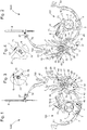
- the invention relates to a timepiece 1000, more particularly a watch, comprising a movement 500 and a striking mechanism 100.
- a timepiece 1000 may also be a music box, or include a music box.
- the striking mechanism 100 conventionally comprises at least one reference mobile, and preferably a plurality of reference mobile, including time reference snails and / or stars, and in particular a minute snail, a quarter snail. , a snail for hours.
- This striking mechanism 100 also comprises at least one striking mobile device 1, as explained in particular in the chapter “Grande Singer” of the book “Complicated watches” and visible in particular in figure 40 of this book.
- This ringing drive mobile 1 conventionally comprises a detent ratchet 2 and a rack pinion.
- the striking mechanism 100 cooperates with the movement 500, which drives the reference mobile (s), and of which a particular output is illustrated on figure 28 , in the nonlimiting form of a star for triggering the ringing by movement, adjusted on a roadway, and comprising four teeth, so as to be able to lift, every quarter of an hour, an intermediate rocker triggering by movement, hereinafter referred to as lifting.
- the ringing drive mobile 1 is thus carrying a detent ratchet 2, which is arranged to cooperate with at least one actuating pawl at the passage 3 controlled by the movement 500, in particular by the cooperation between the star of the figure 28 and the latching lever 73 of the figure 32 , and as set out in the application CH00964 / 17 from the same depositor, or a repeating pawl 4 by a trigger-on-demand latch 5, visible on the figure 29 , operable by a user, for example for a minute repeater control or the like, and as set out in the same application CH00964 / 17 from the same depositor.
- the striking mechanism 100 comprises a striking disengagement lever 6 capable of preventing access of such a pawl 3, 4, to the detent ratchet 2, under the action of a ringing reversal lever 7, such as as described in the requests CH00964 / 17 , CH00965 / 17 , CH00966 / 17 , from the same depositor.
- This ringing reversal flip-flop 7 can be operated either by a time-setting rod 8 which the movement 500 comprises, or else by a main control 10 for selecting ringing or melody which the striking mechanism 100 comprises. , or even by a stopping mechanism in the event of insufficient energy resource included in the ringing mechanism 100.
- Such a stopping mechanism designed to prevent the launch of any ringing when the ringing reserve, in particular at the level of a striking cylinder or similar, is empty or insufficient, is not illustrated or detailed here, and is the subject of the request CH00964 / 17 from the same depositor.
- the ringing mechanism comprises a triggering safety device during a ringing or melody selection, which is arranged to prevent the triggering of any ringing, whether by the movement 500 or by a user.
- This tripping safety device comprises a tripping safety latch 20, the pivoting of which, under the action of a ring or melody selection made on the main control 10 by a user, moves any pawl 3, 4 away from the trigger ratchet 2.
- the striking mechanism 100 comprises elastic return means, which are arranged to return the main control 10 to a single rest position in the absence of action by a user.
- the main control 10 comprises a pivoting main control lever 11, which carries a control pin 12.
- This control pin 12 is arranged to cooperate in support, under the action of a main control spring 9, with a first surface 23 of the trigger safety latch 20 in a first angular travel allowing tripping maneuvers, and with a second surface 24 of the tripping safety latch 20 in a second angular travel of release of the tripping safety latch 20 preventing any ringing tripping maneuver.
- the release safety latch 20 is pushed towards the control pin 12 by the return of a release safety latch spring 29.
- the movement 500 has a fixed pin 28, which serves as a support position for the latch. release safety 20 when the latter is in the rest position.
- control pin 12 In the rest position of the main control 10, the control pin 12 faces the first surface 23, from which it is separated by a first non-zero safety distance S1, as can be seen on the figure. figure 3 .
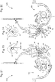
- the control pin 12 bears on the first surface 23, as visible on the figure. figure 7 , where the trigger safety latch 20 is supported on a fixed pin 28 of the movement 500, at the start of an action on the push-button of the main control 10, while, on the figure 11 , the control pin 12 is still resting on the first surface 23, but the release safety latch 20 is no longer resting on the fixed pin 28.
- control pin 12 bears on the second surface 24, as long as a force is exerted on the main control 10 by a user, as seen on the figures 15 and 19 , where the trigger safety latch 20 is moved away from the fixed pin 28.
- the second surface 24 of the trigger safety latch 20 is adjacent to the first surface 23, from which it is separated by an edge or by an intermediate flat, the crossing of which during an action on the main control 10 corresponds at the end of the first angular travel, and when the safety device engages preventing the triggering of any bell.
- the first surface 23 is substantially flat, and is separated from the second surface 24, which is substantially cylindrical, by an edge.
- the second surface 24 is coaxial with the pivot axis of the main control lever 11 when the safety is activated.
- first surface 23 and the second surface 24 are two substantially cylindrical surfaces, and substantially centered on the pivot axis of the main control lever 11, one of which is more distant than the other, and are separated by an intermediate plate. And, in the same way, the second surface 24 is coaxial with the pivot axis of the main control lever 11 when the safety is activated.
- main control 10 which comprises, in the variant illustrated by the figures, a main control rocker 11 on which acts a pushbutton (not shown) which can be operated by the user.
- the ringing reversal lever 7 comprises an eccentric 71, which is arranged to come to bear on a bearing surface 22 which the release safety lever 20 comprises, for the fine adjustment of the pivoting stroke. of the ringing reversal lever 7, and to ensure the release of each pawl 3, 4, relative to the trigger 2.
- This safety is activated during the empty stroke of the main control lever 11: while the control pin 12 moves on the first surface 23, the safety distance gradually changes from the value of the second safety distance S2 to the value zero, and the ringing reversal flip-flop 7 begins to travel to drive the ringing release lever 6 which disconnects the two pawls 3, 4, keeping them away from the trigger 2.
- the ringing reversal latch 7 carries a single pin arranged to cooperate with the bearing surface 22. In yet another variant, not illustrated, the ringing reversal latch 7 carries an opening arranged to cooperate with a pin of the safety release latch 20, or with a pin fixed to the movement plate 500.
- the eccentric 71 faces the bearing surface 22 from which it is separated by a second non-zero safety distance S2, as visible on the figure. figure 4 .
- this eccentric 71 faces the bearing surface 22 from which it is still separated by a second non-zero safety distance S2, as visible on the figure.
- figure 8 at the same time as the figure 7 , at the start of an action on the main control pusher 10, while the control pin 12 is resting on the first surface 23, and the release safety latch 20 is resting on the fixed pin 28.
- the eccentric 71 bears on the bearing surface 22, as long as a force is exerted on the main control 10 by a user, as visible on the figure 16 , at the same time as the figure 15 , which correspond to the end of the empty stroke and the end of the safety engagement phase, as well as to the figure 20 , at the same time as the figure 19 , and which corresponds to the end of the stroke of the pusher, the selection then being made, for example in the form of a change of melody or of ringing mode, or even of choice of timbre, or the like.
- This arrangement makes it possible to prevent any breakage of the mechanism.
- the main control 10 for selecting ring or melody comprises a column wheel 30.
- the main control latch 11 is then a main column wheel control latch, which comprises a column wheel. hook 13, which is arranged to drive teeth 31 of column wheel 30 by traction, which is held in position by a column wheel jumper 32.
- the main control spring 9 is then a main wheel control spring with columns, which comprises at least one pin 93, 94, for its positioning. Licences EP3096189B1 and EP3136188B1 by the same applicant describe the operation of such a column wheel, in connection with such a control rocker.
- the first angular stroke, during which the control pin 12 bears on the first surface 23 of the trigger safety latch 20, corresponds to the empty travel of the main column wheel control latch 11, c ' that is to say that this main column wheel control latch 11 has not yet come into contact with the column wheel 30.
- the first surface 23 alone enables the triggering safety device according to the invention to be engaged.
- the second surface 24 of the tripping safety latch 20 makes it possible to keep this active tripping safety, during the continuation of the travel of the control pin 12 of the main column wheel control latch 11.
- the first part of the first angular stroke corresponds to an empty stroke of the main column wheel control lever 11, between the rest position and the first contact of the hook 13 with the wheel with columns 30.
- the trigger safety lever 20 comprises a support radius 26, which is a mechanical stop safety device.
- the ringing reversal latch 7 is arranged to control a display, visible to a user, of the operating or inoperative mode of the ringing, depending on its angular position.
- a display can in particular be controlled by a release lever 78, articulated on the ringing reversal lever 7 and in indirect connection with the control rod 8 of the movement, the operation of which is explained in the application.
- CH00964 / 17 by the same applicant relating to a ringing stopping mechanism, and which disengaging lever 78 carries a flap visible through a window, or a needle, or the like, making it possible to warn the user of the availability or the unavailability of ringtones.
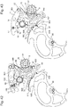
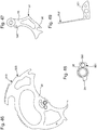
- the striking mechanism 100 conventionally comprises at least one control piece which is a quarter piece or a minute piece for striking the hour on passing or on command, and comprises at least one cam, which is associated with the control part, and which is arranged to prevent the pivoting of the main control 10 for a ringing or melody selection when a ringing or a melody set is in progress, as explained in the patent EP3096189B1 of the same depositor, where, for each stage of a striking mechanism which comprises several thereof, such a cam cooperates with the respective quarter piece to prevent any action on the control pusher when this quarter piece is in motion to effect the play of a ringtone or melody.
- a cam is advantageously here arranged to cooperate with a minute piece, and to pivot to block the main control lever 11 when a ringing or melody is playing.
- the figures 42 to 49 illustrate the advantageous case where this additional safety mechanism cooperates with the 90 minutes coin, which is the last to be played during the execution of a ringing, and which also has the function of stopping the ringing regulator at the end of cycle.
- This additional safety mechanism is intended to prohibit a selection when a bell operates in passing or a bell launched by a minute repeater or the like, and comprises a melody selection safety rocker 95, which is arranged to rest on the part. 90 minutes, by a nozzle 97 that it includes.
- the figures 42 and 44 show the chime at rest, this nozzle 97 rests on a track 910 of the minute part 90, concentric with its pivot axis.
- the melody selection safety latch 95 has a hinge fork 96 with a lug 980, which a melody selection latch 98 pivotally mounted on a bridge has.
- This lock 98 is a cam, and comprises a finger 99 capable of occupying, depending on the angular position of the lock 98, either a position in a pocket 150 of the main control lever 11, delimited by a threshold 15, or a position in opposite this threshold 15, in a position where the safety is engaged.
- a 951 melody selection safety rocker spring which pushes, by an arm 952, the safety melody selection rocker 95 towards the part of minutes 90.
- a pin 999 of the bridge blocks a bearing face 981 of the lock 98.
- the safety is engaged, and will not be retriggered until the 90 minutes coin returns to its rest position, after the ringing has been completed.
- the patent EP3096189B1 illustrates alternative variants of this complementary security mechanism.
- the striking mechanism 100 more particularly comprises a minute repeater or other on-demand sound display, which comprises a trigger-on-demand rocker 5 which can be operated by a user, to cause a repeater pawl 4 to cooperate with the trigger 2.
- the invention relates to such a striking mechanism 100 on its own, which is arranged as an additional mechanism on a striking bridge which can be attached to the movement 500.
- the invention makes it possible, independently of the other securities mentioned in the other patent applications and patents, cited above from the same applicant, and in particular independently of the judgment which is the subject of the application CH00964 / 17 , to ensure total security of the ringing mode and / or melody selection function.
Claims (19)
- Uhr (1000), umfassend ein Uhrwerk (500) und ein Schlagwerk (100) mit einem Schlagwerk-Antriebsdrehteil (1), das ein auslösbares Sperrrad (2) trägt, mit dem zusammenwirkt mindestens ein beim Passieren betätigbarer Sperrkegel (3), gesteuert durch das Uhrwerk (500), oder ein Repetiersperrkegel (4), gesteuert durch eine durch einen Benutzer auf Anforderung betätigbare Auslösewippe (5), wobei das Schlagwerk (100) einen Schlagwerk-Auskupplungshebel (6) umfasst, der geeignet ist, den Zugriff eines der Sperrkegel (3; 4) auf das auslösbare Sperrrad (2) unter der Wirkung einer Schlagumkehrwippe (7) zu verhindern, und der entweder durch einen Zeiteinstellstift (8), den das Uhrwerk (500) aufweist, oder durch eine Hauptsteuerung (10) zum Auswählen eines Schlages oder einer Melodie, die das Schlagwerk (100) besitzt, oder durch einen Mechanismus zum Anhalten, falls der Energievorrat unzureichend ist, den das Schlagwerk (100) aufweist, betätigbar ist, dadurch gekennzeichnet, dass das Schlagwerk eine Auslöseschutzvorrichtung während einer Wahl eines Schlages oder einer Melodie umfasst, die dazu vorgesehen ist, das Auslösen des gesamten Schlages durch das Uhrwerk (500) oder durch einen Benutzer zu verhindern, und die eine Auslöseschutzwippe (20) aufweist, deren Schwenkbewegung unter der Wirkung einer Wahl eines Schlages oder einer Melodie über die Hauptsteuerung (10) durch einen Benutzer jeden Sperrkegel (3; 4) von dem auslösbaren Sperrrad (2) entfernt, und dass das Schlagwerk (100) elastische Rückstellmittel aufweist, um die Hauptsteuerung (10) bei fehlender Einwirkung eines Benutzers in eine einzige Ruheposition zurückzuführen.
- Uhr (1000) nach Anspruch 1, dadurch gekennzeichnet, dass die Hauptsteuerung (10) eine schwenkbare Hauptsteuerwippe (11) umfasst, die einen Steuer-Sperrstift (12) trägt, der so angeordnet ist, dass er unter der Wirkung einer Hauptsteuerfeder (9) mit einer ersten Fläche (23) der Auslöseschutzwippe (20) in einem ersten Winkelhub, der Auslösebetätigungen ermöglicht, und mit einer zweiten Fläche (24) der Auslöseschutzwippe (20) in einem zweiten Winkelhub zum Außer-Eingriff-Bringen der Auslöseschutzwippe (20) abstützend zusammenwirkt, um jegliche Betätigung zum Auslösen des Schlagens zu verhindern, wobei die Auslöseschutzwippe (20) durch das Zurückstellen einer Feder (29) der Auslöseschutzwippe gegen den Steuer-Sperrstift (12) gedrückt wird.
- Uhr (1000) nach Anspruch 2, dadurch gekennzeichnet, dass in der Ruheposition der Hauptsteuerung (10) der Steuer-Sperrstift (12) der ersten Fläche (23) zugewandt ist, von der er um einen von null verschiedenen ersten Sicherheitsabstand S1 beabstandet ist.
- Uhr (1000) nach Anspruch 2 oder 3, dadurch gekennzeichnet, dass während des ersten Winkelhubs, der einem Leerhub der Steuer-Hauptwippe (11) entspricht, der Steuer-Sperrstift (12) sich auf der ersten Fläche (23) abstützt, die dazu vorgesehen ist, den Auslöseschutz einzuschalten.
- Uhr (1000) nach einem der Ansprüche 2 bis 4, dadurch gekennzeichnet, dass sich der Steuer-Sperrstift (12) während des zweiten Winkelhubs auf der zweiten Fläche (24) abstützt, solange durch einen Benutzer eine Kraft auf die Hauptsteuerung (10) ausgeübt wird, um den Auslöseschutz aufrechtzuerhalten.
- Uhr (1000) nach einem der Ansprüche 2 bis 5, dadurch gekennzeichnet, dass die zweite Fläche (24) der Auslöseschutzwippe (20) zu der ersten Fläche (23) benachbart ist und hiervon durch eine Kante oder durch eine Zwischenplatte getrennt ist, deren Überschreitung bei einer Einwirkung auf die Hauptsteuerung (10) dem Ende des ersten Winkelhubs und dem Einschalten des Schutzes entspricht, was das Auslösen des gesamten Schlages verhindert.
- Uhr (1000) nach Anspruch 6, dadurch gekennzeichnet, dass die erste Fläche (23) im Wesentlichen eben ist und durch eine Kante von der zweiten Fläche (24) getrennt ist, die im Wesentlichen zylindrisch und zu der Schwenkachse der Hauptsteuerwippe (11) im Wesentlichen koaxial ist, wenn der Schutz aktiviert ist.
- Uhr (1000) nach Anspruch 6, dadurch gekennzeichnet, dass die erste Fläche (23) und die zweite Fläche (24) zwei im Wesentlichen zylindrische Flächen sind und im Wesentlichen auf die Schwenkachse der Hauptsteuerwippe (11) ausgerichtet sind, von der die eine weiter entfernt ist als die andere, und durch eine Zwischenplatte getrennt sind, und die zweite Fläche (24) zu der Schwenkachse der Hauptsteuerwippe (11) koaxial ist, wenn der Schutz aktiviert ist.
- Uhr (1000) nach einem der Ansprüche 2 bis 8, dadurch gekennzeichnet, dass die Schlagumkehrwippe (7) einen Exzenter (71) aufweist, der dazu vorgesehen ist, auf einer Stützfläche (22), die die Auslöseschutzwippe (20) aufweist, in Auflage zu gelangen, um das Ende des Schwenkhubs der Schlagumkehrwippe (7) zu regulieren und um das Außer-Eingriff-Bringen jedes Sperrkegels (3; 4) vom auslösbaren Sperrrad (2) sicherzustellen.
- Uhr (1000) nach Anspruch 9 und einem der Ansprüche 2 bis 8, dadurch gekennzeichnet, dass in der Ruheposition der Hauptsteuerung (10) der Exzenter (71) der Stützfläche (22) zugewandt ist, von der er um einen zweiten von null verschiedenen Sicherheitsabstand S2 getrennt ist.
- Uhr (1000) nach Anspruch 9 und einem der Ansprüche 2 bis 10, dadurch gekennzeichnet, dass während eines ersten Teils des ersten Winkelhubs der Exzenter (71) der Stützfläche (22) zugewandt ist, von der er um einen zweiten von null verschiedenen Sicherheitsabstand S2 getrennt ist.
- Uhr (1000) nach Anspruch 11, dadurch gekennzeichnet, dass während eines auf den ersten Teil folgenden zweiten Teils des ersten Winkelhubs der Exzenter (71) auf der Stützfläche (22) in Auflage gelangt.
- Uhr (1000) nach Anspruch 9 und einem der Ansprüche 2 bis 12, dadurch gekennzeichnet, dass während des zweiten Winkelhubs der Exzenter (71) auf der Stützfläche (22) in Auflage gelangt, solange durch einen Benutzer eine Kraft auf die Hauptsteuerung (10) ausgeübt wird.
- Uhr (1000) nach einem der Ansprüche 2 bis 13, dadurch gekennzeichnet, dass die Hauptsteuerung (10) zur Wahl eines Schlages oder einer Melodie ein Säulenrad (30) umfasst und dass die Hauptsteuerwippe (11) eine Hauptsteuerwippe des Säulenrades ist, die einen Haken (13) aufweist, der dazu vorgesehen ist, Zähne (31) des Säulenrades (30), das durch eine Säulenrad-Hebelfeder (32) in Position gehalten wird, durch Zug anzutreiben.
- Uhr (1000) nach den Ansprüchen 11 und 14, dadurch gekennzeichnet, dass der erste Teil des ersten Winkelhubs einem Leerhub zwischen der Ruheposition und dem ersten Kontakt des Hakens (13) mit dem Säulenrad (30) entspricht.
- Uhr (1000) nach einem der Ansprüche 1 bis 15, dadurch gekennzeichnet, dass die Schlagumkehrwippe (7) dazu vorgesehen ist, eine für einen Benutzer sichtbare Anzeige des Betriebs oder des Nichtbetriebs des Schlagwerks je nach Winkelposition zu steuern.
- Uhr (1000) nach einem der Ansprüche 1 bis 16, dadurch gekennzeichnet, dass das Schlagwerk (100) mindestens ein Steuerteil umfasst, das ein Viertelrechen oder ein Minutenrechen (90) zum Schlagen der Zeit beim Passieren oder auf Befehl ist, und mindestens einen Nocken (98) umfasst, der dem Steuerteil zugeordnet ist und dazu vorgesehen ist, das Schwenken der Hauptsteuerung (10) für die Wahl eines Schlages oder einer Melodie zu verhindern, wenn gerade ein Schlagen oder ein Abspielen einer Melodie stattfindet.
- Uhr (1000) nach einem der Ansprüche 1 bis 17, dadurch gekennzeichnet, dass das Schlagwerk (100) eine Minutenrepetition oder eine andere auditive Anzeige auf Anforderung umfasst, die eine durch einen Anwender betätigbare Wippe (5) zum Auslösen auf Anforderung aufweist, um das Zusammenwirken eines Repetiersperrkegels mit dem auslösbaren Sperrrad (2) zu bewirken.
- Uhr (1000) nach einem der Ansprüche 1 bis 18, dadurch gekennzeichnet, dass sie eine tragbare Uhr ist.
Priority Applications (6)
| Application Number | Priority Date | Filing Date | Title |
|---|---|---|---|
| EP18174636.3A EP3575886B1 (de) | 2018-05-28 | 2018-05-28 | Uhr mit schlagwerk und einschaltsicherung |
| US16/386,304 US11188031B2 (en) | 2018-05-28 | 2019-04-17 | Timepiece with striking mechanism and release-prevention device |
| JP2019094287A JP6796683B2 (ja) | 2018-05-28 | 2019-05-20 | ストライク機構及びリリース防止デバイスを備えた計時器 |
| KR1020190060691A KR102213575B1 (ko) | 2018-05-28 | 2019-05-23 | 타격 기구 및 릴리스-방지 장치를 갖는 타임피스 |
| CN201910443803.7A CN110543091B (zh) | 2018-05-28 | 2019-05-27 | 具有报时机构和防释放装置的钟表 |
| RU2019116238A RU2706808C1 (ru) | 2018-05-28 | 2019-05-27 | Часы с механизмом боя и устройством предотвращения запуска функции боя |
Applications Claiming Priority (1)
| Application Number | Priority Date | Filing Date | Title |
|---|---|---|---|
| EP18174636.3A EP3575886B1 (de) | 2018-05-28 | 2018-05-28 | Uhr mit schlagwerk und einschaltsicherung |
Publications (2)
| Publication Number | Publication Date |
|---|---|
| EP3575886A1 EP3575886A1 (de) | 2019-12-04 |
| EP3575886B1 true EP3575886B1 (de) | 2021-03-10 |
Family
ID=62455400
Family Applications (1)
| Application Number | Title | Priority Date | Filing Date |
|---|---|---|---|
| EP18174636.3A Active EP3575886B1 (de) | 2018-05-28 | 2018-05-28 | Uhr mit schlagwerk und einschaltsicherung |
Country Status (6)
| Country | Link |
|---|---|
| US (1) | US11188031B2 (de) |
| EP (1) | EP3575886B1 (de) |
| JP (1) | JP6796683B2 (de) |
| KR (1) | KR102213575B1 (de) |
| CN (1) | CN110543091B (de) |
| RU (1) | RU2706808C1 (de) |
Families Citing this family (1)
| Publication number | Priority date | Publication date | Assignee | Title |
|---|---|---|---|---|
| EP3845975B1 (de) * | 2019-12-31 | 2024-03-13 | Omega SA | Sicherheitsvorrichtung und schlagwerkmechanismus |
Family Cites Families (20)
| Publication number | Priority date | Publication date | Assignee | Title |
|---|---|---|---|---|
| DE4012026A1 (de) * | 1990-04-13 | 1991-10-17 | Int Watch Co Iwc | Anschlagvorrichtung |
| ATE302964T1 (de) * | 2002-12-12 | 2005-09-15 | Roth & Genta Haute Horlogerie | Uhr mit schlagwerk |
| RU2279114C2 (ru) * | 2004-07-02 | 2006-06-27 | Виктор Павлович Туровинин | Часы с устройством для отключения механизма боя |
| EP1708051A1 (de) * | 2005-03-31 | 2006-10-04 | Zenith International SA | Uhr mit einem Wecker |
| EP1760551A1 (de) * | 2005-09-01 | 2007-03-07 | Montres Journe SA | Uhr mit Grossem Schlagwerk |
| EP1760545A1 (de) * | 2005-09-01 | 2007-03-07 | Montres Journe S.A. | Uhr mit einem Schlagwerk |
| DE602005010600D1 (de) * | 2005-12-14 | 2008-12-04 | Montres Breguet Sa | Uhr, die einen Schlagwerkmechanismus mit einem einzigen Sperrkegel umfasst |
| EP1933211B1 (de) * | 2006-12-13 | 2009-04-15 | Montres Breguet S.A. | Uhr mit Schlagwerk, die einen Sperrhebel mit doppelter Funktion umfasst |
| DE602006005827D1 (de) * | 2006-12-13 | 2009-04-30 | Montres Breguet Sa | asst |
| CH704591B1 (fr) * | 2011-03-08 | 2016-02-15 | Montres Breguet Sa | Mécanisme de sonnerie à répétition minutes comportant un mécanisme de sécurité contre des manipulations intempestives. |
| EP2498143B1 (de) * | 2011-03-08 | 2018-05-02 | Montres Breguet SA | Isolationsmechanismus zwischen Uhrmechanismen zur Auslösung verschiedener Schlagwerkssignale |
| EP2503405B1 (de) * | 2011-03-22 | 2014-07-30 | Montres Breguet SA | Uhr umfassend einen Schlagwerk sowie einen Mechanismus zur selektiven stoppen dieses Schlagwerks |
| CH708165B1 (fr) * | 2013-06-13 | 2017-10-31 | Patek Philippe Sa Geneve | Mécanisme de sonnerie et pièce d'horlogerie comprenant un tel mécanisme. |
| CN106030421B (zh) * | 2014-02-19 | 2018-11-20 | 萧邦科技公司 | 用于钟表件的响铃机构 |
| EP2947523B1 (de) | 2014-05-21 | 2017-02-01 | Blancpain SA. | Melodieauswahlmechanismus für Schlaguhr |
| CH711112A2 (fr) * | 2015-05-21 | 2016-11-30 | Blancpain Sa | Mécanisme de sécurité de sélection et/ou de déclenchement de sonnerie d'horlogerie. |
| EP3136188B1 (de) * | 2015-08-31 | 2018-04-18 | Blancpain SA. | Mechanismus zum auswählen einer melodie für uhr mit schlagwerk |
| EP3435174B1 (de) * | 2017-07-25 | 2021-06-16 | Blancpain SA | Moduswahlschalter für schlagwerk für armbanduhr oder andere uhr |
| EP3502801B1 (de) * | 2017-12-19 | 2021-02-17 | Omega SA | Repetitionsmechanismus für chronograph mit sicherung |
| EP3502802B1 (de) * | 2017-12-19 | 2021-02-17 | Omega SA | Repetitionsmechanismus für chronograph mit sicherung |
-
2018
- 2018-05-28 EP EP18174636.3A patent/EP3575886B1/de active Active
-
2019
- 2019-04-17 US US16/386,304 patent/US11188031B2/en active Active
- 2019-05-20 JP JP2019094287A patent/JP6796683B2/ja active Active
- 2019-05-23 KR KR1020190060691A patent/KR102213575B1/ko active IP Right Grant
- 2019-05-27 RU RU2019116238A patent/RU2706808C1/ru active
- 2019-05-27 CN CN201910443803.7A patent/CN110543091B/zh active Active
Non-Patent Citations (1)
| Title |
|---|
| None * |
Also Published As
| Publication number | Publication date |
|---|---|
| EP3575886A1 (de) | 2019-12-04 |
| KR20190135417A (ko) | 2019-12-06 |
| US11188031B2 (en) | 2021-11-30 |
| KR102213575B1 (ko) | 2021-02-08 |
| JP6796683B2 (ja) | 2020-12-09 |
| CN110543091A (zh) | 2019-12-06 |
| RU2706808C1 (ru) | 2019-11-21 |
| CN110543091B (zh) | 2021-02-26 |
| US20190361401A1 (en) | 2019-11-28 |
| JP2019207228A (ja) | 2019-12-05 |
Similar Documents
| Publication | Publication Date | Title |
|---|---|---|
| EP3001258B1 (de) | Schlagwerkmechanismus mit unterschiedlichen schlagwerken | |
| EP2453322B1 (de) | Schneller Korrektor einer Zeitgrößenanzeige für Uhr | |
| EP3339977B1 (de) | Mechanische armbanduhr mit glockenspielschlagwerk | |
| EP2038708B1 (de) | Musikmodul eines uhrwerks | |
| EP2498143B1 (de) | Isolationsmechanismus zwischen Uhrmechanismen zur Auslösung verschiedener Schlagwerkssignale | |
| EP2498147B1 (de) | Schlagwerksblock und Antriebsmechanismus für Weckerwerk für Uhren mit Schlagwerken | |
| EP1708051A1 (de) | Uhr mit einem Wecker | |
| EP2498149B1 (de) | Zeitbegrenzungsmechanismus für Uhrmechanismus | |
| EP2498148A1 (de) | Sicherheitsmechanismus gegen fehlerhaften Bedienungen der Steuerungen eines Minuten-repetierwerks | |
| EP3096189B1 (de) | Sicherheitsmechanismus zum ein- und/oder ausschalten eines schlagwerks einer uhr | |
| EP3502802B1 (de) | Repetitionsmechanismus für chronograph mit sicherung | |
| CH689337A5 (fr) | Pièce d'horlogerie à carillon. | |
| EP3136188B1 (de) | Mechanismus zum auswählen einer melodie für uhr mit schlagwerk | |
| EP3435176B1 (de) | Drehmomentglättung für uhr mit einem schlagwerkmechanismus, insbesondere mit schlagwerkmechanismus | |
| EP2226688B1 (de) | Uhr | |
| EP1372117B1 (de) | Chronograph-Mechanismus | |
| EP3502801B1 (de) | Repetitionsmechanismus für chronograph mit sicherung | |
| EP3575886B1 (de) | Uhr mit schlagwerk und einschaltsicherung | |
| EP1770453B1 (de) | Uhr mit Doppelschlagwerk | |
| EP3435174B1 (de) | Moduswahlschalter für schlagwerk für armbanduhr oder andere uhr | |
| EP3108307B1 (de) | Schlagwerkvorrichtung für eine uhr | |
| CH715027B1 (fr) | Pièce d'horlogerie avec mécanisme de sonnerie et dispositif de sécurité de déclenchement. | |
| EP3447591B1 (de) | Moduswahlschalter für schlagwerk, und melodie für armbanduhr oder andere uhr | |
| WO2022214913A1 (fr) | Pièce d'horlogerie à répétition et alarme | |
| CH714033B1 (fr) | Lissage de couple pour pièce d'horlogerie, notamment avec mécanisme de sonnerie. |
Legal Events
| Date | Code | Title | Description |
|---|---|---|---|
| PUAI | Public reference made under article 153(3) epc to a published international application that has entered the european phase |
Free format text: ORIGINAL CODE: 0009012 |
|
| STAA | Information on the status of an ep patent application or granted ep patent |
Free format text: STATUS: THE APPLICATION HAS BEEN PUBLISHED |
|
| AK | Designated contracting states |
Kind code of ref document: A1 Designated state(s): AL AT BE BG CH CY CZ DE DK EE ES FI FR GB GR HR HU IE IS IT LI LT LU LV MC MK MT NL NO PL PT RO RS SE SI SK SM TR |
|
| AX | Request for extension of the european patent |
Extension state: BA ME |
|
| STAA | Information on the status of an ep patent application or granted ep patent |
Free format text: STATUS: REQUEST FOR EXAMINATION WAS MADE |
|
| 17P | Request for examination filed |
Effective date: 20200604 |
|
| RBV | Designated contracting states (corrected) |
Designated state(s): AL AT BE BG CH CY CZ DE DK EE ES FI FR GB GR HR HU IE IS IT LI LT LU LV MC MK MT NL NO PL PT RO RS SE SI SK SM TR |
|
| GRAP | Despatch of communication of intention to grant a patent |
Free format text: ORIGINAL CODE: EPIDOSNIGR1 |
|
| STAA | Information on the status of an ep patent application or granted ep patent |
Free format text: STATUS: GRANT OF PATENT IS INTENDED |
|
| RIC1 | Information provided on ipc code assigned before grant |
Ipc: G04B 23/00 20060101ALI20200925BHEP Ipc: G04B 21/02 20060101ALI20200925BHEP Ipc: G04B 21/12 20060101ALI20200925BHEP Ipc: G04B 21/00 20060101AFI20200925BHEP |
|
| INTG | Intention to grant announced |
Effective date: 20201102 |
|
| GRAS | Grant fee paid |
Free format text: ORIGINAL CODE: EPIDOSNIGR3 |
|
| GRAA | (expected) grant |
Free format text: ORIGINAL CODE: 0009210 |
|
| STAA | Information on the status of an ep patent application or granted ep patent |
Free format text: STATUS: THE PATENT HAS BEEN GRANTED |
|
| AK | Designated contracting states |
Kind code of ref document: B1 Designated state(s): AL AT BE BG CH CY CZ DE DK EE ES FI FR GB GR HR HU IE IS IT LI LT LU LV MC MK MT NL NO PL PT RO RS SE SI SK SM TR |
|
| REG | Reference to a national code |
Ref country code: GB Ref legal event code: FG4D Free format text: NOT ENGLISH |
|
| REG | Reference to a national code |
Ref country code: AT Ref legal event code: REF Ref document number: 1370508 Country of ref document: AT Kind code of ref document: T Effective date: 20210315 Ref country code: CH Ref legal event code: EP |
|
| REG | Reference to a national code |
Ref country code: IE Ref legal event code: FG4D Free format text: LANGUAGE OF EP DOCUMENT: FRENCH |
|
| REG | Reference to a national code |
Ref country code: DE Ref legal event code: R096 Ref document number: 602018013589 Country of ref document: DE |
|
| REG | Reference to a national code |
Ref country code: CH Ref legal event code: NV Representative=s name: ICB INGENIEURS CONSEILS EN BREVETS SA, CH |
|
| REG | Reference to a national code |
Ref country code: LT Ref legal event code: MG9D |
|
| PG25 | Lapsed in a contracting state [announced via postgrant information from national office to epo] |
Ref country code: NO Free format text: LAPSE BECAUSE OF FAILURE TO SUBMIT A TRANSLATION OF THE DESCRIPTION OR TO PAY THE FEE WITHIN THE PRESCRIBED TIME-LIMIT Effective date: 20210610 Ref country code: LT Free format text: LAPSE BECAUSE OF FAILURE TO SUBMIT A TRANSLATION OF THE DESCRIPTION OR TO PAY THE FEE WITHIN THE PRESCRIBED TIME-LIMIT Effective date: 20210310 Ref country code: FI Free format text: LAPSE BECAUSE OF FAILURE TO SUBMIT A TRANSLATION OF THE DESCRIPTION OR TO PAY THE FEE WITHIN THE PRESCRIBED TIME-LIMIT Effective date: 20210310 Ref country code: GR Free format text: LAPSE BECAUSE OF FAILURE TO SUBMIT A TRANSLATION OF THE DESCRIPTION OR TO PAY THE FEE WITHIN THE PRESCRIBED TIME-LIMIT Effective date: 20210611 Ref country code: HR Free format text: LAPSE BECAUSE OF FAILURE TO SUBMIT A TRANSLATION OF THE DESCRIPTION OR TO PAY THE FEE WITHIN THE PRESCRIBED TIME-LIMIT Effective date: 20210310 Ref country code: BG Free format text: LAPSE BECAUSE OF FAILURE TO SUBMIT A TRANSLATION OF THE DESCRIPTION OR TO PAY THE FEE WITHIN THE PRESCRIBED TIME-LIMIT Effective date: 20210610 |
|
| REG | Reference to a national code |
Ref country code: AT Ref legal event code: MK05 Ref document number: 1370508 Country of ref document: AT Kind code of ref document: T Effective date: 20210310 |
|
| REG | Reference to a national code |
Ref country code: NL Ref legal event code: MP Effective date: 20210310 |
|
| PG25 | Lapsed in a contracting state [announced via postgrant information from national office to epo] |
Ref country code: SE Free format text: LAPSE BECAUSE OF FAILURE TO SUBMIT A TRANSLATION OF THE DESCRIPTION OR TO PAY THE FEE WITHIN THE PRESCRIBED TIME-LIMIT Effective date: 20210310 Ref country code: LV Free format text: LAPSE BECAUSE OF FAILURE TO SUBMIT A TRANSLATION OF THE DESCRIPTION OR TO PAY THE FEE WITHIN THE PRESCRIBED TIME-LIMIT Effective date: 20210310 Ref country code: RS Free format text: LAPSE BECAUSE OF FAILURE TO SUBMIT A TRANSLATION OF THE DESCRIPTION OR TO PAY THE FEE WITHIN THE PRESCRIBED TIME-LIMIT Effective date: 20210310 |
|
| PG25 | Lapsed in a contracting state [announced via postgrant information from national office to epo] |
Ref country code: NL Free format text: LAPSE BECAUSE OF FAILURE TO SUBMIT A TRANSLATION OF THE DESCRIPTION OR TO PAY THE FEE WITHIN THE PRESCRIBED TIME-LIMIT Effective date: 20210310 |
|
| PG25 | Lapsed in a contracting state [announced via postgrant information from national office to epo] |
Ref country code: SM Free format text: LAPSE BECAUSE OF FAILURE TO SUBMIT A TRANSLATION OF THE DESCRIPTION OR TO PAY THE FEE WITHIN THE PRESCRIBED TIME-LIMIT Effective date: 20210310 Ref country code: AT Free format text: LAPSE BECAUSE OF FAILURE TO SUBMIT A TRANSLATION OF THE DESCRIPTION OR TO PAY THE FEE WITHIN THE PRESCRIBED TIME-LIMIT Effective date: 20210310 Ref country code: CZ Free format text: LAPSE BECAUSE OF FAILURE TO SUBMIT A TRANSLATION OF THE DESCRIPTION OR TO PAY THE FEE WITHIN THE PRESCRIBED TIME-LIMIT Effective date: 20210310 Ref country code: EE Free format text: LAPSE BECAUSE OF FAILURE TO SUBMIT A TRANSLATION OF THE DESCRIPTION OR TO PAY THE FEE WITHIN THE PRESCRIBED TIME-LIMIT Effective date: 20210310 |
|
| PG25 | Lapsed in a contracting state [announced via postgrant information from national office to epo] |
Ref country code: IS Free format text: LAPSE BECAUSE OF FAILURE TO SUBMIT A TRANSLATION OF THE DESCRIPTION OR TO PAY THE FEE WITHIN THE PRESCRIBED TIME-LIMIT Effective date: 20210710 Ref country code: PT Free format text: LAPSE BECAUSE OF FAILURE TO SUBMIT A TRANSLATION OF THE DESCRIPTION OR TO PAY THE FEE WITHIN THE PRESCRIBED TIME-LIMIT Effective date: 20210712 Ref country code: PL Free format text: LAPSE BECAUSE OF FAILURE TO SUBMIT A TRANSLATION OF THE DESCRIPTION OR TO PAY THE FEE WITHIN THE PRESCRIBED TIME-LIMIT Effective date: 20210310 Ref country code: RO Free format text: LAPSE BECAUSE OF FAILURE TO SUBMIT A TRANSLATION OF THE DESCRIPTION OR TO PAY THE FEE WITHIN THE PRESCRIBED TIME-LIMIT Effective date: 20210310 Ref country code: SK Free format text: LAPSE BECAUSE OF FAILURE TO SUBMIT A TRANSLATION OF THE DESCRIPTION OR TO PAY THE FEE WITHIN THE PRESCRIBED TIME-LIMIT Effective date: 20210310 |
|
| REG | Reference to a national code |
Ref country code: DE Ref legal event code: R097 Ref document number: 602018013589 Country of ref document: DE |
|
| PLBE | No opposition filed within time limit |
Free format text: ORIGINAL CODE: 0009261 |
|
| STAA | Information on the status of an ep patent application or granted ep patent |
Free format text: STATUS: NO OPPOSITION FILED WITHIN TIME LIMIT |
|
| PG25 | Lapsed in a contracting state [announced via postgrant information from national office to epo] |
Ref country code: DK Free format text: LAPSE BECAUSE OF FAILURE TO SUBMIT A TRANSLATION OF THE DESCRIPTION OR TO PAY THE FEE WITHIN THE PRESCRIBED TIME-LIMIT Effective date: 20210310 Ref country code: AL Free format text: LAPSE BECAUSE OF FAILURE TO SUBMIT A TRANSLATION OF THE DESCRIPTION OR TO PAY THE FEE WITHIN THE PRESCRIBED TIME-LIMIT Effective date: 20210310 Ref country code: MC Free format text: LAPSE BECAUSE OF FAILURE TO SUBMIT A TRANSLATION OF THE DESCRIPTION OR TO PAY THE FEE WITHIN THE PRESCRIBED TIME-LIMIT Effective date: 20210310 Ref country code: LU Free format text: LAPSE BECAUSE OF NON-PAYMENT OF DUE FEES Effective date: 20210528 Ref country code: ES Free format text: LAPSE BECAUSE OF FAILURE TO SUBMIT A TRANSLATION OF THE DESCRIPTION OR TO PAY THE FEE WITHIN THE PRESCRIBED TIME-LIMIT Effective date: 20210310 |
|
| REG | Reference to a national code |
Ref country code: BE Ref legal event code: MM Effective date: 20210531 |
|
| 26N | No opposition filed |
Effective date: 20211213 |
|
| PG25 | Lapsed in a contracting state [announced via postgrant information from national office to epo] |
Ref country code: SI Free format text: LAPSE BECAUSE OF FAILURE TO SUBMIT A TRANSLATION OF THE DESCRIPTION OR TO PAY THE FEE WITHIN THE PRESCRIBED TIME-LIMIT Effective date: 20210310 |
|
| PG25 | Lapsed in a contracting state [announced via postgrant information from national office to epo] |
Ref country code: IT Free format text: LAPSE BECAUSE OF FAILURE TO SUBMIT A TRANSLATION OF THE DESCRIPTION OR TO PAY THE FEE WITHIN THE PRESCRIBED TIME-LIMIT Effective date: 20210310 Ref country code: IE Free format text: LAPSE BECAUSE OF NON-PAYMENT OF DUE FEES Effective date: 20210528 |
|
| PG25 | Lapsed in a contracting state [announced via postgrant information from national office to epo] |
Ref country code: IS Free format text: LAPSE BECAUSE OF FAILURE TO SUBMIT A TRANSLATION OF THE DESCRIPTION OR TO PAY THE FEE WITHIN THE PRESCRIBED TIME-LIMIT Effective date: 20210710 |
|
| PG25 | Lapsed in a contracting state [announced via postgrant information from national office to epo] |
Ref country code: BE Free format text: LAPSE BECAUSE OF NON-PAYMENT OF DUE FEES Effective date: 20210531 |
|
| PG25 | Lapsed in a contracting state [announced via postgrant information from national office to epo] |
Ref country code: CY Free format text: LAPSE BECAUSE OF FAILURE TO SUBMIT A TRANSLATION OF THE DESCRIPTION OR TO PAY THE FEE WITHIN THE PRESCRIBED TIME-LIMIT Effective date: 20210310 |
|
| P01 | Opt-out of the competence of the unified patent court (upc) registered |
Effective date: 20230611 |
|
| PG25 | Lapsed in a contracting state [announced via postgrant information from national office to epo] |
Ref country code: HU Free format text: LAPSE BECAUSE OF FAILURE TO SUBMIT A TRANSLATION OF THE DESCRIPTION OR TO PAY THE FEE WITHIN THE PRESCRIBED TIME-LIMIT; INVALID AB INITIO Effective date: 20180528 |
|
| PGFP | Annual fee paid to national office [announced via postgrant information from national office to epo] |
Ref country code: FR Payment date: 20230420 Year of fee payment: 6 Ref country code: DE Payment date: 20230419 Year of fee payment: 6 Ref country code: CH Payment date: 20230602 Year of fee payment: 6 |
|
| PGFP | Annual fee paid to national office [announced via postgrant information from national office to epo] |
Ref country code: GB Payment date: 20230420 Year of fee payment: 6 |
|
| PG25 | Lapsed in a contracting state [announced via postgrant information from national office to epo] |
Ref country code: MK Free format text: LAPSE BECAUSE OF FAILURE TO SUBMIT A TRANSLATION OF THE DESCRIPTION OR TO PAY THE FEE WITHIN THE PRESCRIBED TIME-LIMIT Effective date: 20210310 |