EP3575886B1 - Timepiece with striking mechanism and safety trigger - Google Patents
Timepiece with striking mechanism and safety trigger Download PDFInfo
- Publication number
- EP3575886B1 EP3575886B1 EP18174636.3A EP18174636A EP3575886B1 EP 3575886 B1 EP3575886 B1 EP 3575886B1 EP 18174636 A EP18174636 A EP 18174636A EP 3575886 B1 EP3575886 B1 EP 3575886B1
- Authority
- EP
- European Patent Office
- Prior art keywords
- timepiece
- release
- lever
- strike
- striking mechanism
- Prior art date
- Legal status (The legal status is an assumption and is not a legal conclusion. Google has not performed a legal analysis and makes no representation as to the accuracy of the status listed.)
- Active
Links
Images


Classifications
-
- G—PHYSICS
- G04—HOROLOGY
- G04B—MECHANICALLY-DRIVEN CLOCKS OR WATCHES; MECHANICAL PARTS OF CLOCKS OR WATCHES IN GENERAL; TIME PIECES USING THE POSITION OF THE SUN, MOON OR STARS
- G04B21/00—Indicating the time by acoustic means
- G04B21/02—Regular striking mechanisms giving the full hour, half hour or quarter hour
- G04B21/06—Details of striking mechanisms, e.g. hammer, fan governor
-
- G—PHYSICS
- G04—HOROLOGY
- G04B—MECHANICALLY-DRIVEN CLOCKS OR WATCHES; MECHANICAL PARTS OF CLOCKS OR WATCHES IN GENERAL; TIME PIECES USING THE POSITION OF THE SUN, MOON OR STARS
- G04B21/00—Indicating the time by acoustic means
- G04B21/02—Regular striking mechanisms giving the full hour, half hour or quarter hour
- G04B21/04—Hour wheels; Racks or rakes; Snails or similar control mechanisms
-
- G—PHYSICS
- G04—HOROLOGY
- G04B—MECHANICALLY-DRIVEN CLOCKS OR WATCHES; MECHANICAL PARTS OF CLOCKS OR WATCHES IN GENERAL; TIME PIECES USING THE POSITION OF THE SUN, MOON OR STARS
- G04B13/00—Gearwork
- G04B13/02—Wheels; Pinions; Spindles; Pivots
-
- G—PHYSICS
- G04—HOROLOGY
- G04B—MECHANICALLY-DRIVEN CLOCKS OR WATCHES; MECHANICAL PARTS OF CLOCKS OR WATCHES IN GENERAL; TIME PIECES USING THE POSITION OF THE SUN, MOON OR STARS
- G04B21/00—Indicating the time by acoustic means
-
- G—PHYSICS
- G04—HOROLOGY
- G04B—MECHANICALLY-DRIVEN CLOCKS OR WATCHES; MECHANICAL PARTS OF CLOCKS OR WATCHES IN GENERAL; TIME PIECES USING THE POSITION OF THE SUN, MOON OR STARS
- G04B21/00—Indicating the time by acoustic means
- G04B21/02—Regular striking mechanisms giving the full hour, half hour or quarter hour
- G04B21/12—Reiterating watches or clocks
-
- G—PHYSICS
- G04—HOROLOGY
- G04B—MECHANICALLY-DRIVEN CLOCKS OR WATCHES; MECHANICAL PARTS OF CLOCKS OR WATCHES IN GENERAL; TIME PIECES USING THE POSITION OF THE SUN, MOON OR STARS
- G04B23/00—Arrangements producing acoustic signals at preselected times
-
- G—PHYSICS
- G04—HOROLOGY
- G04B—MECHANICALLY-DRIVEN CLOCKS OR WATCHES; MECHANICAL PARTS OF CLOCKS OR WATCHES IN GENERAL; TIME PIECES USING THE POSITION OF THE SUN, MOON OR STARS
- G04B31/00—Bearings; Point suspensions or counter-point suspensions; Pivot bearings; Single parts therefor
-
- G—PHYSICS
- G04—HOROLOGY
- G04B—MECHANICALLY-DRIVEN CLOCKS OR WATCHES; MECHANICAL PARTS OF CLOCKS OR WATCHES IN GENERAL; TIME PIECES USING THE POSITION OF THE SUN, MOON OR STARS
- G04B9/00—Supervision of the state of winding, e.g. indicating the amount of winding
- G04B9/02—Devices controlled by such state, e.g. device affording protection means against overwinding
Definitions
- the invention relates to a timepiece comprising a movement and a striking mechanism, which comprises a striking mobile carrier carrying a detent ratchet with which is arranged to cooperate at least one actuating pawl in the passage controlled by said passage. movement or a repeating pawl by a trigger on demand latch operable by a user, said strike mechanism comprising a strike release lever capable of preventing access of a said pawl to said trigger ratchet under the action of 'a ringing reversal flip-flop which is operable, either by a time-setting rod which said movement comprises, or else by a main ringing or melody selection control which comprises said ringing mechanism, or else by a stopping mechanism in the event of insufficient energy resource in said ringing mechanism.
- the invention relates to the field of sound display mechanisms for timepieces, and in particular to striking timepieces and / or music boxes, for the execution of bells, chimes, melodies in passing or on demand. More particularly, the invention relates to the field of musical watches, with a mechanical striking movement and / or playing a melody.
- Clockwork striking mechanisms are major complications, complex as much by the number and the complexity of the kinematics of their components, as by the operating modes of which they are capable.
- security management is very complex, and it is difficult to block chimes in passing to allow a minute repeater to play, or conversely to block the launch of a repeater.
- the problem is even more delicate for a timepiece capable of operating according to different ringing modes, with differentiated melodies, in particular a chime, or even with different sets of gongs, when this timepiece comprises means for selecting mode of ringing, melody, stamps. And it is a matter of ensuring total security, not only of the components of the striking mechanism or of the musical mechanism, but also of this selection mechanism, which is also complex. It is especially necessary to prevent the accumulation of stresses in the mechanism, in particular at the level of the lifts, and in particular to prevent any collision between the quarter pieces and the lifts.
- the demand CH01422 / 17 from the same applicant presents a safety mechanism for setting the time, for a striking mechanism with regulator EP2498143A1 concerns an isolation mechanism between watch mechanisms for triggering sound signals.
- the invention more particularly proposes to prevent any triggering of ringing or melody execution, when the user is operating the manual selection means.
- the invention relates to a timepiece according to claim 1.
- the invention relates to a timepiece 1000, more particularly a watch, comprising a movement 500 and a striking mechanism 100.
- a timepiece 1000 may also be a music box, or include a music box.
- the striking mechanism 100 conventionally comprises at least one reference mobile, and preferably a plurality of reference mobile, including time reference snails and / or stars, and in particular a minute snail, a quarter snail. , a snail for hours.
- This striking mechanism 100 also comprises at least one striking mobile device 1, as explained in particular in the chapter “Grande Singer” of the book “Complicated watches” and visible in particular in figure 40 of this book.
- This ringing drive mobile 1 conventionally comprises a detent ratchet 2 and a rack pinion.
- the striking mechanism 100 cooperates with the movement 500, which drives the reference mobile (s), and of which a particular output is illustrated on figure 28 , in the nonlimiting form of a star for triggering the ringing by movement, adjusted on a roadway, and comprising four teeth, so as to be able to lift, every quarter of an hour, an intermediate rocker triggering by movement, hereinafter referred to as lifting.
- the ringing drive mobile 1 is thus carrying a detent ratchet 2, which is arranged to cooperate with at least one actuating pawl at the passage 3 controlled by the movement 500, in particular by the cooperation between the star of the figure 28 and the latching lever 73 of the figure 32 , and as set out in the application CH00964 / 17 from the same depositor, or a repeating pawl 4 by a trigger-on-demand latch 5, visible on the figure 29 , operable by a user, for example for a minute repeater control or the like, and as set out in the same application CH00964 / 17 from the same depositor.
- the striking mechanism 100 comprises a striking disengagement lever 6 capable of preventing access of such a pawl 3, 4, to the detent ratchet 2, under the action of a ringing reversal lever 7, such as as described in the requests CH00964 / 17 , CH00965 / 17 , CH00966 / 17 , from the same depositor.
- This ringing reversal flip-flop 7 can be operated either by a time-setting rod 8 which the movement 500 comprises, or else by a main control 10 for selecting ringing or melody which the striking mechanism 100 comprises. , or even by a stopping mechanism in the event of insufficient energy resource included in the ringing mechanism 100.
- Such a stopping mechanism designed to prevent the launch of any ringing when the ringing reserve, in particular at the level of a striking cylinder or similar, is empty or insufficient, is not illustrated or detailed here, and is the subject of the request CH00964 / 17 from the same depositor.
- the ringing mechanism comprises a triggering safety device during a ringing or melody selection, which is arranged to prevent the triggering of any ringing, whether by the movement 500 or by a user.
- This tripping safety device comprises a tripping safety latch 20, the pivoting of which, under the action of a ring or melody selection made on the main control 10 by a user, moves any pawl 3, 4 away from the trigger ratchet 2.
- the striking mechanism 100 comprises elastic return means, which are arranged to return the main control 10 to a single rest position in the absence of action by a user.
- the main control 10 comprises a pivoting main control lever 11, which carries a control pin 12.
- This control pin 12 is arranged to cooperate in support, under the action of a main control spring 9, with a first surface 23 of the trigger safety latch 20 in a first angular travel allowing tripping maneuvers, and with a second surface 24 of the tripping safety latch 20 in a second angular travel of release of the tripping safety latch 20 preventing any ringing tripping maneuver.
- the release safety latch 20 is pushed towards the control pin 12 by the return of a release safety latch spring 29.
- the movement 500 has a fixed pin 28, which serves as a support position for the latch. release safety 20 when the latter is in the rest position.
- control pin 12 In the rest position of the main control 10, the control pin 12 faces the first surface 23, from which it is separated by a first non-zero safety distance S1, as can be seen on the figure. figure 3 .
- the control pin 12 bears on the first surface 23, as visible on the figure. figure 7 , where the trigger safety latch 20 is supported on a fixed pin 28 of the movement 500, at the start of an action on the push-button of the main control 10, while, on the figure 11 , the control pin 12 is still resting on the first surface 23, but the release safety latch 20 is no longer resting on the fixed pin 28.
- control pin 12 bears on the second surface 24, as long as a force is exerted on the main control 10 by a user, as seen on the figures 15 and 19 , where the trigger safety latch 20 is moved away from the fixed pin 28.
- the second surface 24 of the trigger safety latch 20 is adjacent to the first surface 23, from which it is separated by an edge or by an intermediate flat, the crossing of which during an action on the main control 10 corresponds at the end of the first angular travel, and when the safety device engages preventing the triggering of any bell.
- the first surface 23 is substantially flat, and is separated from the second surface 24, which is substantially cylindrical, by an edge.
- the second surface 24 is coaxial with the pivot axis of the main control lever 11 when the safety is activated.
- first surface 23 and the second surface 24 are two substantially cylindrical surfaces, and substantially centered on the pivot axis of the main control lever 11, one of which is more distant than the other, and are separated by an intermediate plate. And, in the same way, the second surface 24 is coaxial with the pivot axis of the main control lever 11 when the safety is activated.
- main control 10 which comprises, in the variant illustrated by the figures, a main control rocker 11 on which acts a pushbutton (not shown) which can be operated by the user.
- the ringing reversal lever 7 comprises an eccentric 71, which is arranged to come to bear on a bearing surface 22 which the release safety lever 20 comprises, for the fine adjustment of the pivoting stroke. of the ringing reversal lever 7, and to ensure the release of each pawl 3, 4, relative to the trigger 2.
- This safety is activated during the empty stroke of the main control lever 11: while the control pin 12 moves on the first surface 23, the safety distance gradually changes from the value of the second safety distance S2 to the value zero, and the ringing reversal flip-flop 7 begins to travel to drive the ringing release lever 6 which disconnects the two pawls 3, 4, keeping them away from the trigger 2.
- the ringing reversal latch 7 carries a single pin arranged to cooperate with the bearing surface 22. In yet another variant, not illustrated, the ringing reversal latch 7 carries an opening arranged to cooperate with a pin of the safety release latch 20, or with a pin fixed to the movement plate 500.
- the eccentric 71 faces the bearing surface 22 from which it is separated by a second non-zero safety distance S2, as visible on the figure. figure 4 .
- this eccentric 71 faces the bearing surface 22 from which it is still separated by a second non-zero safety distance S2, as visible on the figure.
- figure 8 at the same time as the figure 7 , at the start of an action on the main control pusher 10, while the control pin 12 is resting on the first surface 23, and the release safety latch 20 is resting on the fixed pin 28.
- the eccentric 71 bears on the bearing surface 22, as long as a force is exerted on the main control 10 by a user, as visible on the figure 16 , at the same time as the figure 15 , which correspond to the end of the empty stroke and the end of the safety engagement phase, as well as to the figure 20 , at the same time as the figure 19 , and which corresponds to the end of the stroke of the pusher, the selection then being made, for example in the form of a change of melody or of ringing mode, or even of choice of timbre, or the like.
- This arrangement makes it possible to prevent any breakage of the mechanism.
- the main control 10 for selecting ring or melody comprises a column wheel 30.
- the main control latch 11 is then a main column wheel control latch, which comprises a column wheel. hook 13, which is arranged to drive teeth 31 of column wheel 30 by traction, which is held in position by a column wheel jumper 32.
- the main control spring 9 is then a main wheel control spring with columns, which comprises at least one pin 93, 94, for its positioning. Licences EP3096189B1 and EP3136188B1 by the same applicant describe the operation of such a column wheel, in connection with such a control rocker.
- the first angular stroke, during which the control pin 12 bears on the first surface 23 of the trigger safety latch 20, corresponds to the empty travel of the main column wheel control latch 11, c ' that is to say that this main column wheel control latch 11 has not yet come into contact with the column wheel 30.
- the first surface 23 alone enables the triggering safety device according to the invention to be engaged.
- the second surface 24 of the tripping safety latch 20 makes it possible to keep this active tripping safety, during the continuation of the travel of the control pin 12 of the main column wheel control latch 11.
- the first part of the first angular stroke corresponds to an empty stroke of the main column wheel control lever 11, between the rest position and the first contact of the hook 13 with the wheel with columns 30.
- the trigger safety lever 20 comprises a support radius 26, which is a mechanical stop safety device.
- the ringing reversal latch 7 is arranged to control a display, visible to a user, of the operating or inoperative mode of the ringing, depending on its angular position.
- a display can in particular be controlled by a release lever 78, articulated on the ringing reversal lever 7 and in indirect connection with the control rod 8 of the movement, the operation of which is explained in the application.
- CH00964 / 17 by the same applicant relating to a ringing stopping mechanism, and which disengaging lever 78 carries a flap visible through a window, or a needle, or the like, making it possible to warn the user of the availability or the unavailability of ringtones.
- the striking mechanism 100 conventionally comprises at least one control piece which is a quarter piece or a minute piece for striking the hour on passing or on command, and comprises at least one cam, which is associated with the control part, and which is arranged to prevent the pivoting of the main control 10 for a ringing or melody selection when a ringing or a melody set is in progress, as explained in the patent EP3096189B1 of the same depositor, where, for each stage of a striking mechanism which comprises several thereof, such a cam cooperates with the respective quarter piece to prevent any action on the control pusher when this quarter piece is in motion to effect the play of a ringtone or melody.
- a cam is advantageously here arranged to cooperate with a minute piece, and to pivot to block the main control lever 11 when a ringing or melody is playing.
- the figures 42 to 49 illustrate the advantageous case where this additional safety mechanism cooperates with the 90 minutes coin, which is the last to be played during the execution of a ringing, and which also has the function of stopping the ringing regulator at the end of cycle.
- This additional safety mechanism is intended to prohibit a selection when a bell operates in passing or a bell launched by a minute repeater or the like, and comprises a melody selection safety rocker 95, which is arranged to rest on the part. 90 minutes, by a nozzle 97 that it includes.
- the figures 42 and 44 show the chime at rest, this nozzle 97 rests on a track 910 of the minute part 90, concentric with its pivot axis.
- the melody selection safety latch 95 has a hinge fork 96 with a lug 980, which a melody selection latch 98 pivotally mounted on a bridge has.
- This lock 98 is a cam, and comprises a finger 99 capable of occupying, depending on the angular position of the lock 98, either a position in a pocket 150 of the main control lever 11, delimited by a threshold 15, or a position in opposite this threshold 15, in a position where the safety is engaged.
- a 951 melody selection safety rocker spring which pushes, by an arm 952, the safety melody selection rocker 95 towards the part of minutes 90.
- a pin 999 of the bridge blocks a bearing face 981 of the lock 98.
- the safety is engaged, and will not be retriggered until the 90 minutes coin returns to its rest position, after the ringing has been completed.
- the patent EP3096189B1 illustrates alternative variants of this complementary security mechanism.
- the striking mechanism 100 more particularly comprises a minute repeater or other on-demand sound display, which comprises a trigger-on-demand rocker 5 which can be operated by a user, to cause a repeater pawl 4 to cooperate with the trigger 2.
- the invention relates to such a striking mechanism 100 on its own, which is arranged as an additional mechanism on a striking bridge which can be attached to the movement 500.
- the invention makes it possible, independently of the other securities mentioned in the other patent applications and patents, cited above from the same applicant, and in particular independently of the judgment which is the subject of the application CH00964 / 17 , to ensure total security of the ringing mode and / or melody selection function.
Description
L'invention concerne une pièce d'horlogerie comportant un mouvement et un mécanisme de sonnerie, lequel comporte un mobile entraîneur de sonnerie porteur d'un rochet de détente avec lequel est agencé pour coopérer au moins un cliquet d'actionnement au passage commandé par ledit mouvement ou un cliquet de répétition par une bascule de déclenchement à la demande manœuvrable par un utilisateur, ledit mécanisme de sonnerie comportant un levier de débrayage de sonnerie apte à empêcher l'accès d'un dit cliquet audit rochet de détente sous l'action d'une bascule d'inversion de sonnerie qui est manœuvrable, ou bien par une tige de mise à l'heure que comporte ledit mouvement, ou bien par une commande principale de sélection de sonnerie ou de mélodie que comporte ledit mécanisme de sonnerie, ou bien par un mécanisme d'arrêtage en cas de ressource d'énergie insuffisante que comporte ledit mécanisme de sonnerie.The invention relates to a timepiece comprising a movement and a striking mechanism, which comprises a striking mobile carrier carrying a detent ratchet with which is arranged to cooperate at least one actuating pawl in the passage controlled by said passage. movement or a repeating pawl by a trigger on demand latch operable by a user, said strike mechanism comprising a strike release lever capable of preventing access of a said pawl to said trigger ratchet under the action of 'a ringing reversal flip-flop which is operable, either by a time-setting rod which said movement comprises, or else by a main ringing or melody selection control which comprises said ringing mechanism, or else by a stopping mechanism in the event of insufficient energy resource in said ringing mechanism.
L'invention concerne le domaine des mécanismes d'affichage sonore d'horlogerie, et en particulier des pièces d'horlogerie à sonnerie et/ou boîte à musique, pour l'exécution de sonneries, carillons, mélodies au passage ou à la demande. Plus particulièrement l'invention concerne le domaine des montres musicales, à mouvement mécanique de sonnerie et/ou de jeu de mélodie.The invention relates to the field of sound display mechanisms for timepieces, and in particular to striking timepieces and / or music boxes, for the execution of bells, chimes, melodies in passing or on demand. More particularly, the invention relates to the field of musical watches, with a mechanical striking movement and / or playing a melody.
Les mécanismes de sonnerie d'horlogerie sont de grandes complications, complexes autant par le nombre et la complexité des cinématiques de leurs composants, que selon les modes de fonctionnement dont ils sont capables. Pour les montres comportant des complications supplémentaires telle que répétition minutes, la gestion des sécurités est très complexe, et il est difficile de bloquer des sonneries au passage pour laisser jouer une répétition minutes, ou à l'inverse de bloquer le lancement d'une répétition minutes à l'approche d'une sonnerie au passage, d'empêcher le relancement d'une répétition minutes lorsqu'un cycle de répétition vient d'être lancé, d'empêcher un réglage de minuterie pendant l'exécution d'une sonnerie, ou autre, ces sécurités mettent généralement en œuvre un assez grand nombre d'isolateurs, ce qui complexifie encore le mécanisme et les risques d'interférence.Clockwork striking mechanisms are major complications, complex as much by the number and the complexity of the kinematics of their components, as by the operating modes of which they are capable. For watches with additional complications such as minute repeater, security management is very complex, and it is difficult to block chimes in passing to allow a minute repeater to play, or conversely to block the launch of a repeater. minutes at the approach of a bell in passing, to prevent the restart of a minute repeater when a repetition cycle has just been started, to prevent a timer setting during the execution of a bell, or other, these safeties generally use a fairly large number of insulators, which further complicates the mechanism and the risks of interference.
Le problème est encore plus délicat pour une pièce d'horlogerie capable de fonctionner selon différents modes de sonnerie, avec des mélodies différenciées, notamment un carillon, ou encore avec différents jeux de timbres, quand cette pièce d'horlogerie comporte des moyens de sélection de mode de sonnerie, de mélodie, de timbres. Et il s'agit d'assurer une sécurisation totale, non seulement des composants du mécanisme de sonnerie ou du mécanisme musical, mais aussi de ce mécanisme de sélection, également complexe. Il faut tout particulièrement prévenir les accumulations de contraintes dans le mécanisme, en particulier au niveau des levées, et notamment empêcher toute collision entre les pièces de quarts et les levées.The problem is even more delicate for a timepiece capable of operating according to different ringing modes, with differentiated melodies, in particular a chime, or even with different sets of gongs, when this timepiece comprises means for selecting mode of ringing, melody, stamps. And it is a matter of ensuring total security, not only of the components of the striking mechanism or of the musical mechanism, but also of this selection mechanism, which is also complex. It is especially necessary to prevent the accumulation of stresses in the mechanism, in particular at the level of the lifts, and in particular to prevent any collision between the quarter pieces and the lifts.
Les brevets
L'invention se propose plus particulièrement d'empêcher tout déclenchement de sonnerie ou d'exécution de mélodie, lorsque l'utilisateur est en train de manœuvrer les moyens de sélection manuelle. A cet effet, l'invention concerne une pièce d'horlogerie selon la revendication 1.The invention more particularly proposes to prevent any triggering of ringing or melody execution, when the user is operating the manual selection means. To this end, the invention relates to a timepiece according to
D'autres caractéristiques et avantages de l'invention apparaîtront à la lecture de la description détaillée qui va suivre, en référence aux dessins annexés, où :
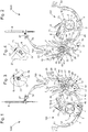
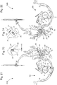
- les
figures 1 à 20 représentent, de façon schématisée et partielle, un même mécanisme de sonnerie selon l'invention, avec une commande manuelle de sélection de mode de sonnerie et/ou de mélodie, à différents instants successifs, par groupes de quatre figures, respectivement en plan recto et verso, et en détail aux deux extrémités d'une bascule de sécurité de déclenchement : - les
figures 1 à 4 en position de repos, la commande manuelle étant inopérante ; - les
figures 5 à 12 illustrent un première course angulaire : - les
figures 5 à 8 lors du début d'une pression sur la commande manuelle dans une première partie de la première course angulaire; - les
figures 9 à 12 lors de la poursuite de cette pression sur la commande manuelle, dans une deuxième partie de la première course angulaire ; - les
figures 13 à 20 illustrent une deuxième course angulaire : - les
figures 13 à 16 à la fin de la course à vide, dans une position où la sécurité est enclenchée ; - les
figures 17 à 20 lors de la fin de course de pression sur la commande manuelle, le changement de mode de sonnerie ou de mélodie étant alors opéré ; - les
figures 21 à 24 illustrent le retour à la position de repos ; - les
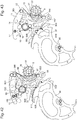
figures 25 à 38 représentent, de façon schématisée, chacune en vue en plan recto-verso et en perspective, les composants principaux du mécanisme de sonnerie ; - la
figure 25 représente un levier de débrayage de sonnerie; - la
figure 26 représente un mobile d'entraînement assemblé, comportant un rochet de détente ; - la
figure 27 représente une bascule intermédiaire de déclenchement, comportant un cliquet d'actionnement au passage, pour le déclenchement de la sonnerie par le mouvement; - la
figure 28 représente une étoile d'enclenchement de grande sonnerie ; - la
figure 29 représente une bascule de déclenchement à la demande, porteuse d'un cliquet de répétition, pour le déclenchement de la sonnerie par l'utilisateur; - la
figure 30 représente une bascule de débrayage; - la
figure 31 représente une bascule d'inversion de sonnerie ; - la
figure 32 représente une bascule d'enclenchement ; - la
figure 33 représente une roue à colonnes ; - la
figure 34 représente un sautoir de roue à colonnes ; - la
figure 35 représente une bascule principale de commande, notamment une bascule de commande de roue à colonnes; - la
figure 36 représente une bascule de sécurité de déclenchement, propre à l'invention; - la
figure 37 représente un ressort de commande de roue à colonnes ; - la
figure 38 représente un ressort de bascule de sécurité de déclenchement ; - la
figure 39 est une vue analogue à lafigure 2 , et sur laquelle est indiquée en trait mixte une trajectoire de coupe, selon laquelle est visible la coupe de lafigure 40 et son détail de lafigure 41 ; - les
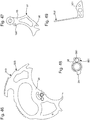
figures 42 à 49 illustrent, en vues en plan, un mécanisme complémentaire de sécurité, en liaison avec une pièce des minutes que comporte le mécanisme de sonnerie, et qui est destiné à interdire une sélection lorsque fonctionne une sonnerie au passage ou une sonnerie lancée par une répétition minutes ou similaire, ce mécanisme complémentaire de sécurité comportant une bascule de sécurité de sélection de mélodie agencée pour venir en appui sur la pièce des minutes, et articulée avec un verrou de sélection de sonnerie, lequel est agencé pour coopérer avec la bascule principale de commande : - la
figure 42 illustre la configuration où la sonnerie est au repos, et où la sécurité est déclenchée ; - la
figure 43 illustre la configuration où la sonnerie est en cours, et où la sécurité est enclenchée ; - les
figures 44 et 45 sont analogues auxfigures 42 et 43 respectivement, des composants ne sont pas représentés, de façon à mieux visualiser le mécanisme ; - la
figure 46 représente la pièce des minutes, laquelle comporte une piste concentrique à son axe de pivotement, interrompue par une rampe de dégagement ; - la
figure 47 représente la bascule de sécurité de sélection de mélodie ; - la
figure 48 représente le verrou de sélection de mélodie, qui est une came coopérant avec la bascule principale de commande de lafigure 35 ; - la
figure 49 représente un ressort de bascule de sécurité de sélection de mélodie, qui pousse celle-ci vers la pièce des minutes; - la figure 50 est un schéma-blocs représentant une pièce d'horlogerie avec un mouvement, une commande manuelle d'affichage sonore à la demande, et un mécanisme de sonnerie selon l'invention.
- the
figures 1 to 20 represent, schematically and partially, the same ringing mechanism according to the invention, with a manual control for selecting ringing mode and / or melody, at different successive instants, in groups of four figures, respectively in front plan and back, and in detail at both ends of a trigger safety latch: - the
figures 1 to 4 in the rest position, the manual control being inoperative; - the
figures 5 to 12 illustrate a first angular stroke: - the
figures 5 to 8 at the start of a pressure on the manual control in a first part of the first angular travel; - the
figures 9 to 12 during the continuation of this pressure on the manual control, in a second part of the first angular travel; - the
figures 13 to 20 illustrate a second angular stroke: - the
figures 13 to 16 at the end of the empty stroke, in a position where the safety is engaged; - the
figures 17 to 20 at the end of the pressure stroke on the manual control, the change of ringing mode or melody then being made; - the
figures 21 to 24 illustrate the return to the rest position; - the
figures 25 to 38 represent, schematically, each in front-to-back plan view and in perspective, the main components of the striking mechanism; - the
figure 25 represents a bell disengaging lever; - the
figure 26 shows an assembled drive mobile, comprising a trigger ratchet; - the
figure 27 shows an intermediate triggering latch, comprising an actuating pawl in passing, for triggering the bell by movement; - the
figure 28 represents a large bell interlocking star; - the
figure 29 shows a trigger on demand flip-flop, carrying a repeating pawl, for triggering the ringing by the user; - the
figure 30 represents a release lever; - the
figure 31 represents a ring reversal flip-flop; - the
figure 32 represents a latching latch; - the
figure 33 represents a column wheel; - the
figure 34 represents a column wheel jumper; - the
figure 35 represents a main control rocker, in particular a column wheel control rocker; - the
figure 36 represents a triggering safety latch, specific to the invention; - the
figure 37 shows a column wheel control spring; - the
figure 38 shows a trigger safety latch spring; - the
figure 39 is a view similar to thefigure 2 , and on which is indicated in phantom a cutting path, according to which is visible the cut of thefigure 40 and its detail of thefigure 41 ; - the
figures 42 to 49 illustrate, in plan views, an additional safety mechanism, in connection with a minute piece that the striking mechanism includes, and which is intended to prohibit a selection when operating a bell in passing or a bell launched by a minute repeater or similar, this complementary safety mechanism comprising a melody selection safety rocker arranged to rest on the minute piece, and articulated with a ringing selection lock, which is arranged to cooperate with the main control rocker: - the
figure 42 illustrates the configuration where the buzzer is idle, and where the security is triggered; - the
figure 43 illustrates the configuration where the ringing is in progress, and where the safety is activated; - the
figures 44 and 45 are analogous tofigures 42 and 43 respectively, components are not shown, so as to better visualize the mechanism; - the
figure 46 represents the minute coin, which has a track concentric with its pivot axis, interrupted by a release ramp; - the
figure 47 represents the melody selection safety toggle; - the
figure 48 represents the melody selection lock, which is a cam cooperating with the main control rocker of thefigure 35 ; - the
figure 49 represents a melody selection safety toggle spring, which pushes the latter towards the minute piece; - FIG. 50 is a block diagram showing a timepiece with a movement, a manual sound display control on demand, and a striking mechanism according to the invention.
L'invention concerne une pièce d'horlogerie 1000, plus particulièrement une montre, comportant un mouvement 500 et un mécanisme de sonnerie 100. Une telle pièce d'horlogerie 1000 peut encore être une boîte à musique, ou comporter une boîte à musique.The invention relates to a
L'ouvrage de
- sonneries,
- répétition antique,
- répétition à quarts moderne,
- répétition simplifiée,
- répétition demi-quarts,
- répétition demi-quarts Breguet,
- répétition cinq minutes,
- répétition à minutes,
- grande sonnerie.
- ringtones,
- ancient repetition,
- modern quarter repeat,
- simplified repetition,
- half-quarter repetition,
- Breguet half-quarter repeat,
- five-minute repetition,
- minute repeater,
- big bell.
Sauf nécessité, ces mécanismes de base ne seront pas repris ici en détail, le spécialiste des sonneries saura en retrouver la constitution dans cet ouvrage de référence universel, en particulier dans les deux derniers chapitres cités ci-dessus.Unless necessary, these basic mechanisms will not be repeated here in detail; the specialist in ring tones will be able to find their constitution in this universal reference work, in particular in the last two chapters cited above.
Le mécanisme de sonnerie 100 comporte, de façon classique, au moins un mobile de référence, et de préférence une pluralité de mobiles de référence, comportant des limaçons et/ou étoiles de référence temporelle, et notamment un limaçon des minutes, un limaçon des quarts, un limaçon des heures.The
Ce mécanisme de sonnerie 100 comporte encore au moins un mobile entraîneur de sonnerie 1, tel qu'exposé notamment au chapitre « grande sonnerie » de l'ouvrage « Les montres compliquées » et visible notamment en
Le mécanisme de sonnerie 100 coopère avec le mouvement 500, qui entraîne le ou les mobiles de référence, et dont une sortie particulière est illustrée à la
Le mobile entraîneur de sonnerie 1 est ainsi porteur d'un rochet de détente 2, lequel est agencé pour coopérer avec au moins un cliquet d'actionnement au passage 3 commandé par le mouvement 500, notamment par la coopération entre l'étoile de la
Le mécanisme de sonnerie 100 comporte un levier de débrayage de sonnerie 6 apte à empêcher l'accès d'un tel cliquet 3, 4, au rochet de détente 2, sous l'action d'une bascule d'inversion de sonnerie 7, telle que décrite dans les demandes
Selon l'invention, le mécanisme de sonnerie comporte un dispositif de sécurité de déclenchement durant une sélection de sonnerie ou de mélodie, qui est agencé pour empêcher le déclenchement de toute sonnerie, que ce soit par le mouvement 500 ou par un utilisateur. Ce dispositif de sécurité de déclenchement comporte une bascule de sécurité de déclenchement 20, dont le pivotement, sous l'action d'une sélection de sonnerie ou de mélodie effectuée sur la commande principale 10 par un utilisateur, éloigne tout cliquet 3, 4, du rochet de détente 2. Et le mécanisme de sonnerie 100 comporte des moyens de rappel élastique, qui sont agencés pour ramener la commande principale 10 dans une position unique de repos en l'absence d'action d'un utilisateur.According to the invention, the ringing mechanism comprises a triggering safety device during a ringing or melody selection, which is arranged to prevent the triggering of any ringing, whether by the
Plus particulièrement, la commande principale 10 comporte une bascule principale de commande 11 pivotante, qui porte une goupille de commande 12. Cette goupille de commande 12 est agencée pour coopérer en appui, sous l'action d'un ressort principal de commande 9, avec une première surface 23 de la bascule de sécurité de déclenchement 20 dans une première course angulaire autorisant des manœuvres de déclenchement, et avec une deuxième surface 24 de la bascule de sécurité de déclenchement 20 dans une deuxième course angulaire de dégagement de la bascule de sécurité de déclenchement 20 interdisant toute manœuvre de déclenchement de sonnerie. La bascule de sécurité de déclenchement 20 est poussée vers la goupille de commande 12 par le rappel d'un ressort de bascule de sécurité de déclenchement 29. Le mouvement 500 comporte une goupille fixe 28, qui sert de position d'appui à la bascule de sécurité de déclenchement 20 lorsque cette dernière est en position de repos.More particularly, the
Dans la position de repos de la commande principale 10, la goupille de commande 12 fait face à la première surface 23, dont elle est séparée d'une première distance de sécurité S1 non nulle, tel que visible sur la
Pendant la première course angulaire, la goupille de commande 12 est en appui sur la première surface 23, tel que visible sur la
Pendant la deuxième course angulaire, la goupille de commande 12 est en appui sur la deuxième surface 24, tant qu'un effort est exercé sur la commande principale 10 par un utilisateur, tel que visible sur les
Plus particulièrement, la deuxième surface 24 de la bascule de sécurité de déclenchement 20 est adjacente à la première surface 23, dont elle est séparée par une arête ou par un plat intermédiaire, dont le franchissement lors d'une action sur la commande principale 10 correspond à la fin de la première course angulaire, et à l'enclenchement de la sécurité empêchant le déclenchement de toute sonnerie.More particularly, the
Dans la variante non limitative illustrée par les figures, la première surface 23 est sensiblement plate, et est séparée de la deuxième surface 24, sensiblement cylindrique, par une arête. La deuxième surface 24 est coaxiale avec l'axe de pivotement de la bascule principale de commande 11 lorsque la sécurité est activée.In the non-limiting variant illustrated by the figures, the
Dans une autre variante non illustrée, la première surface 23 et la deuxième surface 24 sont deux surfaces sensiblement cylindriques, et sensiblement axées sur l'axe de pivotement de la bascule principale de commande 11, dont l'une est plus éloignée que l'autre, et sont séparées par un plat intermédiaire. Et, de la même façon, la deuxième surface 24 est coaxiale avec l'axe de pivotement de la bascule principale de commande 11 lorsque la sécurité est activée.In another variant not shown, the
D'autres agencements sont naturellement possibles, et dépendent notamment de l'espace disponible au voisinage de la commande principale 10, laquelle comporte, dans la variante illustrée par les figures, une bascule principale de commande 11 sur laquelle agit un poussoir non représenté manœuvrable par l'utilisateur.Other arrangements are naturally possible, and depend in particular on the space available in the vicinity of the
De façon avantageuse, la bascule d'inversion de sonnerie 7 comporte un excentrique 71, qui est agencé pour venir en appui sur une surface d'appui 22 que comporte la bascule de sécurité de déclenchement 20, pour le réglage fin de la course de pivotement de la bascule d'inversion de sonnerie 7, et pour assurer le dégagement de chaque cliquet 3, 4, par rapport au rochet de détente 2.Advantageously, the ringing
Lorsque la goupille de commande 12 entre en contact avec la première surface 23 de la bascule de sécurité de déclenchement 20, cette dernière entre en contact avec l'excentrique 71 par sa surface d'appui 22.When the
Cette sécurité s'active pendant la course à vide de la bascule principale de commande 11 : pendant que la goupille de commande 12 se déplace sur la première surface 23, la distance de sécurité passe progressivement de la valeur de la deuxième distance de sécurité S2 à la valeur nulle, et la bascule d'inversion de sonnerie 7 entame sa course pour entraîner le levier de débrayage de sonnerie 6 qui déconnecte les deux cliquets 3, 4, en les maintenant à distance du rochet de détente 2.This safety is activated during the empty stroke of the main control lever 11: while the
Lorsque l'utilisateur fait une sélection de mélodie par une action sur la bascule principale de commande 11, la goupille de commande 12 passe de la première surface 23 à la deuxième surface 24 de la bascule de sécurité de déclenchement 20. De ce fait, la bascule principale de commande 11 entre en contact, avec sa surface d'appui 22, sur cet excentrique 71 de la bascule d'inversion de sonnerie 7, laquelle vient ensuite déconnecter les cliquets 3, 4, par la connexion avec le levier de débrayage de sonnerie 6.When the user makes a melody selection by an action on the
Dans une autre variante non illustrée, la bascule d'inversion de sonnerie 7 porte une simple goupille agencée pour coopérer avec la surface d'appui 22. Dans une autre variante encore, non illustrée, la bascule d'inversion de sonnerie 7 porte une ouverture agencée pour coopérer avec une goupille de la bascule de sécurité de déclenchement 20, ou avec une goupille fixée à la platine du mouvement 500.In another variant, not illustrated, the ringing
Plus particulièrement, dans la position de repos de la commande principale 10, l'excentrique 71 fait face à la surface d'appui 22 dont elle est séparée d'une deuxième distance de sécurité S2 non nulle, tel que visible sur la
Pendant une première partie de la première course angulaire, cet excentrique 71 fait face à la surface d'appui 22 dont elle est encore séparée d'une deuxième distance de sécurité S2 non nulle, tel que visible sur la
Pendant une deuxième partie, consécutive à la première partie, de la première course angulaire, tel que visible sur la
Pendant la deuxième course angulaire, l'excentrique 71 est en appui sur la surface d'appui 22, tant qu'un effort est exercé sur la commande principale 10 par un utilisateur, tel que visible sur la
Dans la version non limitative illustrée par les figures, la commande principale 10 de sélection de sonnerie ou de mélodie comporte une roue à colonnes 30. Et la bascule principale de commande 11 est alors une bascule principale de commande de roue à colonnes, qui comporte un crochet 13, qui est agencé pour entraîner par traction des dents 31 de la roue à colonnes 30, laquelle est maintenue en position par un sautoir de roue à colonnes 32. Et le ressort principal de commande 9 est alors un ressort principal de commande de roue à colonnes, qui comporte au moins un pion 93, 94, pour son positionnement. Les brevets
La première course angulaire, lors de laquelle la goupille de commande 12 est en appui sur la première surface 23 de la bascule de sécurité de déclenchement 20, correspond à la course à vide de la bascule principale de commande de roue à colonnes 11, c'est-à-dire que cette bascule principale de commande de roue à colonnes 11 n'est pas encore entrée en contact avec la roue à colonnes 30.The first angular stroke, during which the
La première surface 23 permet à elle seule d'enclencher la sécurité de déclenchement selon l'invention. La deuxième surface 24 de la bascule de sécurité de déclenchement 20 permet de conserver cette sécurité de déclenchement active, lors de la suite de la course de la goupille de commande 12 de la bascule principale de commande de roue à colonnes 11.The
D'autres variantes non illustrées peuvent comporter d'autres types de sélecteurs qu'une roue à colonnes, le crochet est alors remplacé par un organe de commande adapté à cet usage. Il est notamment possible d'implanter un sélecteur à came, ou à navette comme pour un chronographe. Le brevet
Dans la variante illustrée avec roue à colonnes, la première partie de la première course angulaire correspond à une course à vide de la bascule principale de commande de roue à colonnes 11, entre la position de repos et le premier contact du crochet 13 avec la roue à colonnes 30.In the variant illustrated with column wheel, the first part of the first angular stroke corresponds to an empty stroke of the main column
Dans une variante particulière, la bascule de sécurité de déclenchement 20 comporte un rayon d'appui 26, qui est une sécurité de butée mécanique.In a particular variant, the
Dans une variante particulière, la bascule d'inversion de sonnerie 7 est agencée pour commander un affichage, visible par un utilisateur, du mode opérant ou inopérant de la sonnerie, selon sa position angulaire. Un tel affichage peut notamment être commandé par une bascule de débrayage 78, articulée sur la bascule d'inversion de sonnerie 7 et en liaison indirecte avec la tige de commande 8 du mouvement, dont le fonctionnement est exposé dans la demande
Le mécanisme est aussi avantageusement conçu pour interdire une action sur le mécanisme de sélection, lors du fonctionnement d'une sonnerie au passage ou d'une répétition minutes. A cet effet, plus particulièrement, le mécanisme de sonnerie 100 comporte classiquement au moins une pièce de commande qui est une pièce des quarts ou une pièce des minutes pour la sonnerie de l'heure au passage ou à la commande, et comporte au moins une came, qui est associée à la pièce de commande, et qui est agencée pour interdire le pivotement de la commande principale 10 pour une sélection de sonnerie ou de mélodie quand une sonnerie ou un jeu de mélodie est en cours, tel qu'exposé dans le brevet
Les
Les
Lors du jeu de la sonnerie, selon les
Une goupille 999 du pont bloque une face d'appui 981 du verrou 98. La sécurité est enclenchée, et ne sera redéclenchée que lors du retour de la pièce des minutes 90 à sa position de repos, après l'exécution complète de la sonnerie. Le brevet
Le mécanisme de sonnerie 100 comporte plus particulièrement une répétition minutes ou un autre affichage sonore à la demande, qui comporte une bascule de déclenchement à la demande 5 manœuvrable par un utilisateur, pour faire coopérer un cliquet de répétition 4 avec le rochet de détente 2.The
Dans une variante, l'invention concerne un tel mécanisme de sonnerie 100 seul, qui est agencé comme mécanisme additionnel sur un pont de sonnerie qui peut être rapportés sur le mouvement 500.In a variant, the invention relates to such a
L'invention permet, indépendamment des autres sécurités évoquées dans les autres demandes de brevet et brevets, cités plus haut du même déposant, et en particulier indépendamment de l'arrêtage objet de la demande
Claims (19)
- Timepiece (1000) including a movement (500) and a striking mechanism (100), which includes a strike drive wheel set (1) carrying a detent ratchet (2) which is arranged to cooperate with at least one passing strike actuation click (3) controlled by said movement (500) or a repeater click (4) controlled by a user-operated, on-demand release lever (5), said striking mechanism (100) including a strike-uncoupling lever (6) able to prevent access of a said click (3; 4) to said detent ratchet (2) under the action of a strike reversing lever (7) which is operable, either by a hand-setting stem (8) comprised in said movement (500), or by a main strike or tune selection control member (10) comprised in said striking mechanism (100), or, in case of insufficient energy resource, by a stopping mechanism comprised in said striking mechanism (100), characterized in that said striking mechanism includes a safety device for preventing release during selection of a strike function or tune, which is arranged to prevent the release of any strike function, either by said movement (500) or by a user, and which includes a release-prevention lever (20), the pivoting of which, when a strike function or tune selection is made on said main control member (10) by a user, moves any said click (3, 4) away from said detent ratchet (2), and in that said striking mechanism (100) includes elastic return means for returning said main control member (10) to a unique rest position in the absence of action by a user.
- Timepiece (1000) according to claim 1, characterized in that said main control member (10) includes a pivoting main operating lever (11), which carries a control pin (12) which is arranged to abuttingly engage, under the action of a main operating spring (9), with a first surface (23) of said release-prevention lever (20) in a first angular travel allowing release operations, and with a second surface (24) of said release-prevention lever (20) in a second angular disengagement travel of said release-prevention lever (20) preventing any operations to release the striking mechanism, said release-prevention lever (20) being pushed towards said control pin (12) by the return force of a release-prevention lever spring (29).
- Timepiece (1000) according to claim 2, characterized in that, in said rest position of said main control member (10), said control pin (12) faces said first surface (23) from which it is separated by a first, non-zero safety distance S1.
- Timepiece (1000) according to claim 2 or 3, characterized in that, during said first angular travel which corresponds to an idle travel of said main operating lever (11), said control pin (12) rests on said first surface (23) which is arranged to engage said release-prevention device.
- Timepiece (1000) according to any of claims 2 to 4, characterized in that, during said second angular travel, said control pin (12) rests on said second surface (24), while a force is exerted on said main control member (10) by a user, to maintain said release-prevention safety function.
- Timepiece (1000) according to any of claims 2 to 5, characterized in that said second surface (24) of said release-prevention lever (20) is adjacent to said first surface (23), from which it is separated by an edge or by an intermediate flat portion, the crossing of which during action on said main control member (10) corresponds to the end of said first angular travel, and to the engagement of the safety device preventing the release of any strike function.
- Timepiece (1000) according to claim 6, characterized in that said first surface (23) is substantially flat, and separated by an edge from said second surface (24) which is substantially cylindrical and coaxial with the axis of pivoting of said main operating lever (11) when the safety device is activated.
- Timepiece (1000) according to claim 6, characterized in that said first surface (23) and said second surface (24) are two surfaces which are substantially cylindrical and substantially centred on the axis of pivoting of said main operating lever (11), one of which is further away than the other, and which are separated by an intermediate flat portion, and said second surface (24) is coaxial with the axis of pivoting of said main operating lever (11) when the safety device is activated.
- Timepiece (1000) according to any of claims 2 to 8, characterized in that said strike reversing lever (7) includes an eccentric (71) arranged to move into abutment on a bearing surface (22) comprised in said release-prevention lever (20), for fine adjustment of the pivoting travel of said strike reversing lever (7), and to ensure the disengagement of each said click (3; 4) from said detent ratchet (2).
- Timepiece (1000) according to claim 9 and any of claims 2 to 8, characterized in that, in said rest position of said main control member (10), said eccentric (71) faces said bearing surface (22) from which it is separated by a second, non-zero safety distance S2.
- Timepiece (1000) according to claim 9 and any of claims 2 to 10, characterized in that, during a first part of said first angular travel, said eccentric (71) faces said bearing surface (22) from which it is separated by a second, non-zero safety distance S2.
- Timepiece (1000) according to claim 11, characterized in that, during a second part of said first angular travel, consecutive to said first part, said eccentric (71) rests on said bearing surface (22).
- Timepiece (1000) according to claim 9 and any of claims 2 to 12, characterized in that, during said second angular travel, said eccentric (71) rests on said bearing surface (22), while a force is exerted on said main control member (10) by a user.
- Timepiece (1000) according to any of claims 2 to 13, characterized in that said main strike function or tune selection control member (10) includes a column wheel (30), and in that said main operating lever (11) is a main column wheel operating lever, which includes a hook (13) arranged to pull teeth (31) of said column wheel (30), which is held in position by a column wheel jumper (32).
- Timepiece (1000) according to claims 11 and 14, characterized in that said first part of said first angular travel corresponds to an idle travel between the rest position and the first contact between said hook (13) and said column wheel (30).
- Timepiece (1000) according to any of claims 1 to 15, characterized in that said strike reversing lever (7) is arranged to control a display, visible to the user, of the operating or inoperative mode of the striking mechanism, according to its angular position.
- Timepiece (1000) according to any of claims 1 to 16, characterized in that said striking mechanism (100) includes at least one control rack which is a quarter rack or a minute rack (90) for striking the time automatically or on-demand, and includes at least one cam (98) associated with said control rack and arranged to prevent said main control member (10) pivoting to select a strike mode or tune when a strike function or tune is in progress.
- Timepiece (1000) according to any of claims 1 to 17, characterized in that said striking mechanism (100) includes a minute repeater or another on-demand acoustic display, which includes a said on-demand release lever (5) operable by a user to cause a repeater click (4) to cooperate with said detent ratchet (2).
- Timepiece (1000) according to any of claims 1 to 18, characterized in that the timepiece is a watch.
Priority Applications (6)
| Application Number | Priority Date | Filing Date | Title |
|---|---|---|---|
| EP18174636.3A EP3575886B1 (en) | 2018-05-28 | 2018-05-28 | Timepiece with striking mechanism and safety trigger |
| US16/386,304 US11188031B2 (en) | 2018-05-28 | 2019-04-17 | Timepiece with striking mechanism and release-prevention device |
| JP2019094287A JP6796683B2 (en) | 2018-05-28 | 2019-05-20 | Timekeeper with strike mechanism and release prevention device |
| KR1020190060691A KR102213575B1 (en) | 2018-05-28 | 2019-05-23 | Timepiece with striking mechanism and release-prevention device |
| RU2019116238A RU2706808C1 (en) | 2018-05-28 | 2019-05-27 | Clock with a stroke mechanism and a device for preventing the launch of a stroke function |
| CN201910443803.7A CN110543091B (en) | 2018-05-28 | 2019-05-27 | Timepiece with striking mechanism and anti-release device |
Applications Claiming Priority (1)
| Application Number | Priority Date | Filing Date | Title |
|---|---|---|---|
| EP18174636.3A EP3575886B1 (en) | 2018-05-28 | 2018-05-28 | Timepiece with striking mechanism and safety trigger |
Publications (2)
| Publication Number | Publication Date |
|---|---|
| EP3575886A1 EP3575886A1 (en) | 2019-12-04 |
| EP3575886B1 true EP3575886B1 (en) | 2021-03-10 |
Family
ID=62455400
Family Applications (1)
| Application Number | Title | Priority Date | Filing Date |
|---|---|---|---|
| EP18174636.3A Active EP3575886B1 (en) | 2018-05-28 | 2018-05-28 | Timepiece with striking mechanism and safety trigger |
Country Status (6)
| Country | Link |
|---|---|
| US (1) | US11188031B2 (en) |
| EP (1) | EP3575886B1 (en) |
| JP (1) | JP6796683B2 (en) |
| KR (1) | KR102213575B1 (en) |
| CN (1) | CN110543091B (en) |
| RU (1) | RU2706808C1 (en) |
Families Citing this family (1)
| Publication number | Priority date | Publication date | Assignee | Title |
|---|---|---|---|---|
| EP3845975B1 (en) * | 2019-12-31 | 2024-03-13 | Omega SA | Safety device and ringing mechanism |
Family Cites Families (20)
| Publication number | Priority date | Publication date | Assignee | Title |
|---|---|---|---|---|
| DE4012026A1 (en) * | 1990-04-13 | 1991-10-17 | Int Watch Co Iwc | ANCHOR DEVICE |
| EP1429214B8 (en) * | 2002-12-12 | 2005-12-28 | Daniel Roth et Gerald Genta Haute Horlogerie SA | Timepiece provided with striking mechanism |
| RU2279114C2 (en) * | 2004-07-02 | 2006-06-27 | Виктор Павлович Туровинин | Clock with device for disabling striking mechanism |
| EP1708051A1 (en) * | 2005-03-31 | 2006-10-04 | Zenith International SA | Timepiece comprising an alarm |
| EP1760551A1 (en) * | 2005-09-01 | 2007-03-07 | Montres Journe SA | Timepiece with Grand Strike |
| EP1760545A1 (en) * | 2005-09-01 | 2007-03-07 | Montres Journe S.A. | Timepiece with a striking mechanism |
| EP1798610B1 (en) * | 2005-12-14 | 2008-10-22 | Montres Breguet S.A. | Timepiece including a single-pawl striking mechanism |
| ATE428959T1 (en) * | 2006-12-13 | 2009-05-15 | Montres Breguet Sa | CLOCK WITH STRIKE THAT INCLUDES A DUAL FUNCTION LOCKING LEVER |
| DE602006005827D1 (en) * | 2006-12-13 | 2009-04-30 | Montres Breguet Sa | asst |
| CH704591B1 (en) * | 2011-03-08 | 2016-02-15 | Montres Breguet Sa | striking mechanism minute repeater with a safety mechanism against accidental manipulation. |
| EP2498143B1 (en) * | 2011-03-08 | 2018-05-02 | Montres Breguet SA | Isolation mechanism between timepiece mechanisms for setting off different acoustic signals |
| EP2503405B1 (en) * | 2011-03-22 | 2014-07-30 | Montres Breguet SA | Timepiece comprising a striking mechanism and a mechanism for selectively stopping said striking mechanism. |
| CH708165B1 (en) * | 2013-06-13 | 2017-10-31 | Patek Philippe Sa Geneve | Bell mechanism and timepiece including such mechanism. |
| CN106030421B (en) * | 2014-02-19 | 2018-11-20 | 萧邦科技公司 | Acoustic means for timepiece |
| EP2947523B1 (en) | 2014-05-21 | 2017-02-01 | Blancpain SA. | Melody selection mechanism for a timepiece with striking mechanism |
| CH711112A2 (en) | 2015-05-21 | 2016-11-30 | Blancpain Sa | Selection security mechanism and / or clock ringing trigger. |
| CH711475B1 (en) * | 2015-08-31 | 2019-09-30 | Blancpain Sa | Timepiece with bell. |
| EP3435174B1 (en) * | 2017-07-25 | 2021-06-16 | Blancpain SA | Chime mode selector for watch or timepiece |
| EP3502801B1 (en) * | 2017-12-19 | 2021-02-17 | Omega SA | Chronograph repetition mechanism with safety |
| EP3502802B1 (en) * | 2017-12-19 | 2021-02-17 | Omega SA | Chronograph repetition mechanism with safety |
-
2018
- 2018-05-28 EP EP18174636.3A patent/EP3575886B1/en active Active
-
2019
- 2019-04-17 US US16/386,304 patent/US11188031B2/en active Active
- 2019-05-20 JP JP2019094287A patent/JP6796683B2/en active Active
- 2019-05-23 KR KR1020190060691A patent/KR102213575B1/en active IP Right Grant
- 2019-05-27 CN CN201910443803.7A patent/CN110543091B/en active Active
- 2019-05-27 RU RU2019116238A patent/RU2706808C1/en active
Non-Patent Citations (1)
| Title |
|---|
| None * |
Also Published As
| Publication number | Publication date |
|---|---|
| KR20190135417A (en) | 2019-12-06 |
| JP2019207228A (en) | 2019-12-05 |
| JP6796683B2 (en) | 2020-12-09 |
| US11188031B2 (en) | 2021-11-30 |
| US20190361401A1 (en) | 2019-11-28 |
| RU2706808C1 (en) | 2019-11-21 |
| EP3575886A1 (en) | 2019-12-04 |
| KR102213575B1 (en) | 2021-02-08 |
| CN110543091A (en) | 2019-12-06 |
| CN110543091B (en) | 2021-02-26 |
Similar Documents
| Publication | Publication Date | Title |
|---|---|---|
| EP3001258B1 (en) | Ringing mechanism with differentiated ringtones | |
| EP2453322B1 (en) | Fast time quantity indicator corrector for a timepiece | |
| EP3339977B1 (en) | Mechanical watch with a chiming ringer | |
| EP2038708B1 (en) | Musical module of a movement of a watch | |
| EP2498147B1 (en) | Ringer block and wake-up alarm drive mechanism for ringing timepiece | |
| EP2498143B1 (en) | Isolation mechanism between timepiece mechanisms for setting off different acoustic signals | |
| EP1708051A1 (en) | Timepiece comprising an alarm | |
| EP2498149B1 (en) | Duration limiter mechanism for timepiece mechanism | |
| EP2498148A1 (en) | Safety mechanism against accidental operation of the controls of a minute-repeater | |
| EP3096189B1 (en) | Safety mechanism for selecting and/or triggering timepiece striking-work | |
| EP3502802B1 (en) | Chronograph repetition mechanism with safety | |
| CH689337A5 (en) | Clock which reproduces Westminster Abbey chimes | |
| EP3136188B1 (en) | Melody selection mechanism for a chiming timepiece | |
| EP3435176B1 (en) | Torque smoothing for timepiece with chiming mechanism, in particular with chiming mechanism | |
| EP2226688B1 (en) | Timepiece | |
| EP1372117B1 (en) | Mechanism for chronograph | |
| EP3502801B1 (en) | Chronograph repetition mechanism with safety | |
| EP3575886B1 (en) | Timepiece with striking mechanism and safety trigger | |
| EP1770453B1 (en) | Timepiece incorporating a double striking mechanism | |
| EP3435174B1 (en) | Chime mode selector for watch or timepiece | |
| EP3108307B1 (en) | Striking mechanism for a clock piece | |
| CH715027B1 (en) | Timepiece with striking mechanism and release safety device. | |
| EP3447591B1 (en) | Chime and melody mode selector for watch or timepiece | |
| EP4320487A1 (en) | Timepiece with repeater and alarm functions | |
| CH714033B1 (en) | Torque smoothing for timepieces, in particular with striking mechanism. |
Legal Events
| Date | Code | Title | Description |
|---|---|---|---|
| PUAI | Public reference made under article 153(3) epc to a published international application that has entered the european phase |
Free format text: ORIGINAL CODE: 0009012 |
|
| STAA | Information on the status of an ep patent application or granted ep patent |
Free format text: STATUS: THE APPLICATION HAS BEEN PUBLISHED |
|
| AK | Designated contracting states |
Kind code of ref document: A1 Designated state(s): AL AT BE BG CH CY CZ DE DK EE ES FI FR GB GR HR HU IE IS IT LI LT LU LV MC MK MT NL NO PL PT RO RS SE SI SK SM TR |
|
| AX | Request for extension of the european patent |
Extension state: BA ME |
|
| STAA | Information on the status of an ep patent application or granted ep patent |
Free format text: STATUS: REQUEST FOR EXAMINATION WAS MADE |
|
| 17P | Request for examination filed |
Effective date: 20200604 |
|
| RBV | Designated contracting states (corrected) |
Designated state(s): AL AT BE BG CH CY CZ DE DK EE ES FI FR GB GR HR HU IE IS IT LI LT LU LV MC MK MT NL NO PL PT RO RS SE SI SK SM TR |
|
| GRAP | Despatch of communication of intention to grant a patent |
Free format text: ORIGINAL CODE: EPIDOSNIGR1 |
|
| STAA | Information on the status of an ep patent application or granted ep patent |
Free format text: STATUS: GRANT OF PATENT IS INTENDED |
|
| RIC1 | Information provided on ipc code assigned before grant |
Ipc: G04B 23/00 20060101ALI20200925BHEP Ipc: G04B 21/02 20060101ALI20200925BHEP Ipc: G04B 21/12 20060101ALI20200925BHEP Ipc: G04B 21/00 20060101AFI20200925BHEP |
|
| INTG | Intention to grant announced |
Effective date: 20201102 |
|
| GRAS | Grant fee paid |
Free format text: ORIGINAL CODE: EPIDOSNIGR3 |
|
| GRAA | (expected) grant |
Free format text: ORIGINAL CODE: 0009210 |
|
| STAA | Information on the status of an ep patent application or granted ep patent |
Free format text: STATUS: THE PATENT HAS BEEN GRANTED |
|
| AK | Designated contracting states |
Kind code of ref document: B1 Designated state(s): AL AT BE BG CH CY CZ DE DK EE ES FI FR GB GR HR HU IE IS IT LI LT LU LV MC MK MT NL NO PL PT RO RS SE SI SK SM TR |
|
| REG | Reference to a national code |
Ref country code: GB Ref legal event code: FG4D Free format text: NOT ENGLISH |
|
| REG | Reference to a national code |
Ref country code: AT Ref legal event code: REF Ref document number: 1370508 Country of ref document: AT Kind code of ref document: T Effective date: 20210315 Ref country code: CH Ref legal event code: EP |
|
| REG | Reference to a national code |
Ref country code: IE Ref legal event code: FG4D Free format text: LANGUAGE OF EP DOCUMENT: FRENCH |
|
| REG | Reference to a national code |
Ref country code: DE Ref legal event code: R096 Ref document number: 602018013589 Country of ref document: DE |
|
| REG | Reference to a national code |
Ref country code: CH Ref legal event code: NV Representative=s name: ICB INGENIEURS CONSEILS EN BREVETS SA, CH |
|
| REG | Reference to a national code |
Ref country code: LT Ref legal event code: MG9D |
|
| PG25 | Lapsed in a contracting state [announced via postgrant information from national office to epo] |
Ref country code: NO Free format text: LAPSE BECAUSE OF FAILURE TO SUBMIT A TRANSLATION OF THE DESCRIPTION OR TO PAY THE FEE WITHIN THE PRESCRIBED TIME-LIMIT Effective date: 20210610 Ref country code: LT Free format text: LAPSE BECAUSE OF FAILURE TO SUBMIT A TRANSLATION OF THE DESCRIPTION OR TO PAY THE FEE WITHIN THE PRESCRIBED TIME-LIMIT Effective date: 20210310 Ref country code: FI Free format text: LAPSE BECAUSE OF FAILURE TO SUBMIT A TRANSLATION OF THE DESCRIPTION OR TO PAY THE FEE WITHIN THE PRESCRIBED TIME-LIMIT Effective date: 20210310 Ref country code: GR Free format text: LAPSE BECAUSE OF FAILURE TO SUBMIT A TRANSLATION OF THE DESCRIPTION OR TO PAY THE FEE WITHIN THE PRESCRIBED TIME-LIMIT Effective date: 20210611 Ref country code: HR Free format text: LAPSE BECAUSE OF FAILURE TO SUBMIT A TRANSLATION OF THE DESCRIPTION OR TO PAY THE FEE WITHIN THE PRESCRIBED TIME-LIMIT Effective date: 20210310 Ref country code: BG Free format text: LAPSE BECAUSE OF FAILURE TO SUBMIT A TRANSLATION OF THE DESCRIPTION OR TO PAY THE FEE WITHIN THE PRESCRIBED TIME-LIMIT Effective date: 20210610 |
|
| REG | Reference to a national code |
Ref country code: AT Ref legal event code: MK05 Ref document number: 1370508 Country of ref document: AT Kind code of ref document: T Effective date: 20210310 |
|
| REG | Reference to a national code |
Ref country code: NL Ref legal event code: MP Effective date: 20210310 |
|
| PG25 | Lapsed in a contracting state [announced via postgrant information from national office to epo] |
Ref country code: SE Free format text: LAPSE BECAUSE OF FAILURE TO SUBMIT A TRANSLATION OF THE DESCRIPTION OR TO PAY THE FEE WITHIN THE PRESCRIBED TIME-LIMIT Effective date: 20210310 Ref country code: LV Free format text: LAPSE BECAUSE OF FAILURE TO SUBMIT A TRANSLATION OF THE DESCRIPTION OR TO PAY THE FEE WITHIN THE PRESCRIBED TIME-LIMIT Effective date: 20210310 Ref country code: RS Free format text: LAPSE BECAUSE OF FAILURE TO SUBMIT A TRANSLATION OF THE DESCRIPTION OR TO PAY THE FEE WITHIN THE PRESCRIBED TIME-LIMIT Effective date: 20210310 |
|
| PG25 | Lapsed in a contracting state [announced via postgrant information from national office to epo] |
Ref country code: NL Free format text: LAPSE BECAUSE OF FAILURE TO SUBMIT A TRANSLATION OF THE DESCRIPTION OR TO PAY THE FEE WITHIN THE PRESCRIBED TIME-LIMIT Effective date: 20210310 |
|
| PG25 | Lapsed in a contracting state [announced via postgrant information from national office to epo] |
Ref country code: SM Free format text: LAPSE BECAUSE OF FAILURE TO SUBMIT A TRANSLATION OF THE DESCRIPTION OR TO PAY THE FEE WITHIN THE PRESCRIBED TIME-LIMIT Effective date: 20210310 Ref country code: AT Free format text: LAPSE BECAUSE OF FAILURE TO SUBMIT A TRANSLATION OF THE DESCRIPTION OR TO PAY THE FEE WITHIN THE PRESCRIBED TIME-LIMIT Effective date: 20210310 Ref country code: CZ Free format text: LAPSE BECAUSE OF FAILURE TO SUBMIT A TRANSLATION OF THE DESCRIPTION OR TO PAY THE FEE WITHIN THE PRESCRIBED TIME-LIMIT Effective date: 20210310 Ref country code: EE Free format text: LAPSE BECAUSE OF FAILURE TO SUBMIT A TRANSLATION OF THE DESCRIPTION OR TO PAY THE FEE WITHIN THE PRESCRIBED TIME-LIMIT Effective date: 20210310 |
|
| PG25 | Lapsed in a contracting state [announced via postgrant information from national office to epo] |
Ref country code: IS Free format text: LAPSE BECAUSE OF FAILURE TO SUBMIT A TRANSLATION OF THE DESCRIPTION OR TO PAY THE FEE WITHIN THE PRESCRIBED TIME-LIMIT Effective date: 20210710 Ref country code: PT Free format text: LAPSE BECAUSE OF FAILURE TO SUBMIT A TRANSLATION OF THE DESCRIPTION OR TO PAY THE FEE WITHIN THE PRESCRIBED TIME-LIMIT Effective date: 20210712 Ref country code: PL Free format text: LAPSE BECAUSE OF FAILURE TO SUBMIT A TRANSLATION OF THE DESCRIPTION OR TO PAY THE FEE WITHIN THE PRESCRIBED TIME-LIMIT Effective date: 20210310 Ref country code: RO Free format text: LAPSE BECAUSE OF FAILURE TO SUBMIT A TRANSLATION OF THE DESCRIPTION OR TO PAY THE FEE WITHIN THE PRESCRIBED TIME-LIMIT Effective date: 20210310 Ref country code: SK Free format text: LAPSE BECAUSE OF FAILURE TO SUBMIT A TRANSLATION OF THE DESCRIPTION OR TO PAY THE FEE WITHIN THE PRESCRIBED TIME-LIMIT Effective date: 20210310 |
|
| REG | Reference to a national code |
Ref country code: DE Ref legal event code: R097 Ref document number: 602018013589 Country of ref document: DE |
|
| PLBE | No opposition filed within time limit |
Free format text: ORIGINAL CODE: 0009261 |
|
| STAA | Information on the status of an ep patent application or granted ep patent |
Free format text: STATUS: NO OPPOSITION FILED WITHIN TIME LIMIT |
|
| PG25 | Lapsed in a contracting state [announced via postgrant information from national office to epo] |
Ref country code: DK Free format text: LAPSE BECAUSE OF FAILURE TO SUBMIT A TRANSLATION OF THE DESCRIPTION OR TO PAY THE FEE WITHIN THE PRESCRIBED TIME-LIMIT Effective date: 20210310 Ref country code: AL Free format text: LAPSE BECAUSE OF FAILURE TO SUBMIT A TRANSLATION OF THE DESCRIPTION OR TO PAY THE FEE WITHIN THE PRESCRIBED TIME-LIMIT Effective date: 20210310 Ref country code: MC Free format text: LAPSE BECAUSE OF FAILURE TO SUBMIT A TRANSLATION OF THE DESCRIPTION OR TO PAY THE FEE WITHIN THE PRESCRIBED TIME-LIMIT Effective date: 20210310 Ref country code: LU Free format text: LAPSE BECAUSE OF NON-PAYMENT OF DUE FEES Effective date: 20210528 Ref country code: ES Free format text: LAPSE BECAUSE OF FAILURE TO SUBMIT A TRANSLATION OF THE DESCRIPTION OR TO PAY THE FEE WITHIN THE PRESCRIBED TIME-LIMIT Effective date: 20210310 |
|
| REG | Reference to a national code |
Ref country code: BE Ref legal event code: MM Effective date: 20210531 |
|
| 26N | No opposition filed |
Effective date: 20211213 |
|
| PG25 | Lapsed in a contracting state [announced via postgrant information from national office to epo] |
Ref country code: SI Free format text: LAPSE BECAUSE OF FAILURE TO SUBMIT A TRANSLATION OF THE DESCRIPTION OR TO PAY THE FEE WITHIN THE PRESCRIBED TIME-LIMIT Effective date: 20210310 |
|
| PG25 | Lapsed in a contracting state [announced via postgrant information from national office to epo] |
Ref country code: IT Free format text: LAPSE BECAUSE OF FAILURE TO SUBMIT A TRANSLATION OF THE DESCRIPTION OR TO PAY THE FEE WITHIN THE PRESCRIBED TIME-LIMIT Effective date: 20210310 Ref country code: IE Free format text: LAPSE BECAUSE OF NON-PAYMENT OF DUE FEES Effective date: 20210528 |
|
| PG25 | Lapsed in a contracting state [announced via postgrant information from national office to epo] |
Ref country code: IS Free format text: LAPSE BECAUSE OF FAILURE TO SUBMIT A TRANSLATION OF THE DESCRIPTION OR TO PAY THE FEE WITHIN THE PRESCRIBED TIME-LIMIT Effective date: 20210710 |
|
| PG25 | Lapsed in a contracting state [announced via postgrant information from national office to epo] |
Ref country code: BE Free format text: LAPSE BECAUSE OF NON-PAYMENT OF DUE FEES Effective date: 20210531 |
|
| PG25 | Lapsed in a contracting state [announced via postgrant information from national office to epo] |
Ref country code: CY Free format text: LAPSE BECAUSE OF FAILURE TO SUBMIT A TRANSLATION OF THE DESCRIPTION OR TO PAY THE FEE WITHIN THE PRESCRIBED TIME-LIMIT Effective date: 20210310 |
|
| P01 | Opt-out of the competence of the unified patent court (upc) registered |
Effective date: 20230611 |
|
| PG25 | Lapsed in a contracting state [announced via postgrant information from national office to epo] |
Ref country code: HU Free format text: LAPSE BECAUSE OF FAILURE TO SUBMIT A TRANSLATION OF THE DESCRIPTION OR TO PAY THE FEE WITHIN THE PRESCRIBED TIME-LIMIT; INVALID AB INITIO Effective date: 20180528 |
|
| PGFP | Annual fee paid to national office [announced via postgrant information from national office to epo] |
Ref country code: FR Payment date: 20230420 Year of fee payment: 6 Ref country code: DE Payment date: 20230419 Year of fee payment: 6 Ref country code: CH Payment date: 20230602 Year of fee payment: 6 |
|
| PGFP | Annual fee paid to national office [announced via postgrant information from national office to epo] |
Ref country code: GB Payment date: 20230420 Year of fee payment: 6 |