EP2503405B1 - Timepiece comprising a striking mechanism and a mechanism for selectively stopping said striking mechanism. - Google Patents
Timepiece comprising a striking mechanism and a mechanism for selectively stopping said striking mechanism. Download PDFInfo
- Publication number
- EP2503405B1 EP2503405B1 EP11159238.2A EP11159238A EP2503405B1 EP 2503405 B1 EP2503405 B1 EP 2503405B1 EP 11159238 A EP11159238 A EP 11159238A EP 2503405 B1 EP2503405 B1 EP 2503405B1
- Authority
- EP
- European Patent Office
- Prior art keywords
- timepiece
- movement
- pivot axis
- cam
- striking
- Prior art date
- Legal status (The legal status is an assumption and is not a legal conclusion. Google has not performed a legal analysis and makes no representation as to the accuracy of the status listed.)
- Active
Links
Images


Classifications
-
- G—PHYSICS
- G04—HOROLOGY
- G04B—MECHANICALLY-DRIVEN CLOCKS OR WATCHES; MECHANICAL PARTS OF CLOCKS OR WATCHES IN GENERAL; TIME PIECES USING THE POSITION OF THE SUN, MOON OR STARS
- G04B9/00—Supervision of the state of winding, e.g. indicating the amount of winding
- G04B9/02—Devices controlled by such state, e.g. device affording protection means against overwinding
-
- G—PHYSICS
- G04—HOROLOGY
- G04B—MECHANICALLY-DRIVEN CLOCKS OR WATCHES; MECHANICAL PARTS OF CLOCKS OR WATCHES IN GENERAL; TIME PIECES USING THE POSITION OF THE SUN, MOON OR STARS
- G04B21/00—Indicating the time by acoustic means
- G04B21/02—Regular striking mechanisms giving the full hour, half hour or quarter hour
- G04B21/10—Releasing or locking the regular stroke, e.g. for silence during the night
-
- G—PHYSICS
- G04—HOROLOGY
- G04B—MECHANICALLY-DRIVEN CLOCKS OR WATCHES; MECHANICAL PARTS OF CLOCKS OR WATCHES IN GENERAL; TIME PIECES USING THE POSITION OF THE SUN, MOON OR STARS
- G04B21/00—Indicating the time by acoustic means
- G04B21/02—Regular striking mechanisms giving the full hour, half hour or quarter hour
- G04B21/12—Reiterating watches or clocks
-
- G—PHYSICS
- G04—HOROLOGY
- G04B—MECHANICALLY-DRIVEN CLOCKS OR WATCHES; MECHANICAL PARTS OF CLOCKS OR WATCHES IN GENERAL; TIME PIECES USING THE POSITION OF THE SUN, MOON OR STARS
- G04B23/00—Arrangements producing acoustic signals at preselected times
- G04B23/02—Alarm clocks
-
- G—PHYSICS
- G04—HOROLOGY
- G04B—MECHANICALLY-DRIVEN CLOCKS OR WATCHES; MECHANICAL PARTS OF CLOCKS OR WATCHES IN GENERAL; TIME PIECES USING THE POSITION OF THE SUN, MOON OR STARS
- G04B23/00—Arrangements producing acoustic signals at preselected times
- G04B23/02—Alarm clocks
- G04B23/12—Alarm watches to be worn in pockets or on the wrist
-
- G—PHYSICS
- G04—HOROLOGY
- G04B—MECHANICALLY-DRIVEN CLOCKS OR WATCHES; MECHANICAL PARTS OF CLOCKS OR WATCHES IN GENERAL; TIME PIECES USING THE POSITION OF THE SUN, MOON OR STARS
- G04B9/00—Supervision of the state of winding, e.g. indicating the amount of winding
- G04B9/005—Supervision of the state of winding, e.g. indicating the amount of winding by optical indication of the amount of winding
Definitions
- the invention relates to a selective stop mechanism, as a function of the available engine torque of the motor means that a timepiece comprises, ringtones of said timepiece which comprises a movement, and a power reserve control mechanism.
- said motor means which comprises an output shaft whose angular position indicates the power reserve available at said motor means, and which timepiece further comprises a striking mechanism controlled by a striking mechanism, and further comprises a blocking latch, which is arranged to block the operation of said movement.
- the invention also relates to a timepiece comprising motor means, a movement, a power reserve control mechanism of said motor means which comprises an output shaft whose angular position indicates the power reserve available at said motor means. , a striking mechanism controlled by a striking control mechanism, which comprises a latch blocking said movement.
- the invention relates to the field of watchmaking, and in particular portable timepieces such as watches or the like, whose energy reserve is limited.
- the invention relates to timepieces with complications, and particularly to ringing, because of the significant energy consumption made by such complications.
- Stopping the functions of a complicated timepiece is always problematic, whether it is the sudden stop of the movement, or the stopping of certain complications, especially when they are working. because the restart often requires adjustment of certain functions, when reloading the motor means for the restart of the timepiece.
- the stopping of all or part of these functions, and / or movement are heavy energy consumers, and the stopping of striking mechanisms makes it possible to prevent an unwanted stop during execution, or of a particular ring, or of the execution by the movement of a particular complication that the piece contains.
- the known mechanisms of power reserve control do not make it possible to intervene by estimating the energy levels according to the consumptions of the complications, and they do not allow a successive stop of the various functionalities, according to their energy consumption. .
- the known mechanisms of power reserve control do not make it possible to intervene by estimating the energy levels according to the consumptions of the complications, and they do not allow a successive stop of the various functionalities, according to their energy consumption. .
- the locking mechanism comprises means for alternately engaging the pivoting cam to move it between its two positions.
- the invention relates to a timepiece as defined in claim 1.
- the invention relates to the field of watchmaking, and in particular portable timepieces such as watches or the like, whose energy reserve is limited.
- the invention relates to timepieces with complications, and particularly to ringing, because of the significant energy consumption made by such complications.
- the invention is described here, without limitation, for a timepiece whose some complications are ring tones.
- the invention can be used in a similar manner to manage various energy consuming functions or complications, so as to establish between these functions survival priorities, when the available energy potential decreases, while guaranteeing the return of each function to a rest stage, to guarantee a normal restart during the energy supply of the timepiece concerned.
- the invention relates to a mechanism 760 for selectively stopping ringtones of a timepiece 1000 having a striking mechanism 100, depending on the available engine torque.
- This timepiece comprises a movement 200, and motor means 120, constituted by a barrel or a set of barrels, or the like.
- This timepiece 1000 comprises a ringer control mechanism 1, which is arranged to drive this ringer mechanism 100, and which comprises a device for triggering the stop movement 200 by action on a control lever or the like.
- This movement stop control device comprises as an entry point a blocking latch 771, in particular of the stop-seconds type in the example of the figures.
- the mechanism 760 is arranged for, directly or indirectly, in at least one of its operating positions, to prohibit the execution of a ring, by blocking a control lift for the execution of a ring, which is, in a non-limiting variant, a hammer control lift for percussion of a tone, gong or the like, or a similar sounding mechanism of a ring or a music box, or by direct blocking of such a hammer or similar.
- the mechanism 760 is advantageously arranged to control, deferred in time, the stopping of certain ringtones relative to each other.
- the mechanism 760 is further arranged for, directly or indirectly, in at least one of its operating positions, to block the operation of the movement by a pivoting control action of the blocking lever 771 or of the stop control device of the movement concerned. .
- the invention is here more specifically described, in no way limiting, with the control of such a blocking latch 771.
- the invention allows the timepiece to manage, through this mechanism 760, the torque available at these motor means 120, limiting or not the ringtones, whether they are armed or not. , or by stopping the movement 200 when the power reserve is insufficient to ensure proper operation.
- This mode of operation is useful for a complicated timepiece, since such a controlled stop of the movement or the striking mechanisms makes it possible to prevent an unwanted stoppage during execution, or of a particular ring, or of the execution by the movement of a particular complication that the piece comprises.
- the invention thus makes it possible to reduce each complication in a mode of rest, before its complete stop. The subsequent restart is then guaranteed, in the integrity of all functions, and no adjustment or offset other than the time setting is necessary when reloading the motor means 120 for the restart of the timepiece.
- the invention is thus adapted to the control of a timepiece 1000 or a movement 200 which includes a power reserve control mechanism 750, which comprises an output shaft 751.
- the invention uses information relating to the power reserve available at these motor means 120, constituted by the position angular of this output shaft 751, to control a recess mechanism of all or part of the ringtones available at the ringing mechanism 100, or stop motion 200.
- the mechanism 760 is it designed for, when reloading the motor means 120 by winding or the like, to release successively the functions that it had blocked, as soon as the energy sufficient for their correct operation is again available.
- This output shaft 751 supports a cam 752, which cooperates with a feeler 753 that includes a transmission mechanism 755, to control, directly or indirectly, the movement of a rake 756.
- the cam 752 is preferably, as shown in the figures, a snail-cam, of substantially uniform growth radius, the smallest radius corresponding to the maximum arming position of the motor means 120 of the Figure 1A , and the largest radius corresponding to the disarming position of the motor means 120 of the Figure 4A .
- This rake 756 controls the pivoting of an isolation wheel 770, which comprises the selective stop mechanism 760, and which is arranged to control the position of the blocking lever 771 as a function of the angular position of the parking shaft. output 751, and preferably by acting on a spout 786 that includes the latch 771.
- the ring arresting cam 783 has a plurality of peripheral slots 784.
- peripheral slots 784 In the particular embodiment illustrated by the figures, which corresponds to a use for a ringing mechanism 100 which comprises several ring modes, which are switchable by action on a control linkage, and in particular a mode where all the ring tones operate automatically or under manual control of a user, and another mode where the ringtones are only possible in automatic, these notches are four in number: 784A, 784B, 784C, 784D, as visible on the figure 9 .
- Each of these notches 784 is arranged to cooperate, in a particular angular position of the cam 783, with a spout 795 that includes a pawl 789 pushed towards the pivot axis DP by a spring 791.
- the notch 784A corresponds to the minimum level of power reserve, at which the stop of the movement 200 must be triggered.
- the notch 784D corresponds to the maximum level of power reserve, where the motor means 120 are at their maximum capacity, and where the mechanism 760 exerts no hindrance action, neither on the striking mechanism 100, nor on the movement 200.
- the intermediate notches correspond to positions where one chooses to stop, respectively, the operation of all the automatic tones, and the operation of all the ringtones including on manual control of the user.
- This cam 783 is carrying a pin 778 substantially parallel to its pivot axis DP, and protruding from an upper side of a substantially plane flange which comprises at its periphery the notches 784, to cooperate with the other stages of the mobile d isolation 770.
- the cam 783 further comprises a pin 783A protruding substantially parallel to its pivot axis DP and located on a lower side opposite to the upper side of this flange.
- This stud 783A is arranged to fit into the percussion kinematic chain of a striking mechanism 100, and in particular, in the preferred embodiment illustrated by the figures, on the trajectory of a hammer, between the hammer and a stamp or the like, according to the angular position of the ring arresting cam 783.
- the pin 783A is interposed between a first trigger hammer specific to these ringtones, not shown in the figures, and the stamp, or the like, corresponding.
- the pin 783A is still interposed between a second trigger hammer specific to these ringtones, not shown on the figures, and the stamp, or the like, corresponding.
- the mechanism 760 blocks the movement 200, as will be explained later.
- the ring arresting wheel 745 has an external toothed sector 779, which is arranged to cooperate with a set of teeth 788 of the rake 756.
- This ring arresting wheel 745 has an oblong slot 777, which allows a limited movement of the pin 778 of the cam 783, which limits the relative pivoting of the ring arresting wheel 745 relative to the ring arresting cam 783.
- the ring arresting wheel 745 carries a swivel pivot 747 of a two-spout lift 797, which has a first spout 798 rotated about the swivel axis DP, and a second spout. 799 moving away radially substantially.
- the ring arresting wheel 745 carries a raising spring 796 797 in a position tending to reduce the extreme radial position of the second spout 799, and tending to rotate the lift 797 clockwise on the figure 5 .
- the ring arresting wheel 745 comprises, on one of its faces which is, in the example illustrated by the figures, a lower face which is turned towards the upper face of the cam 783, a peripheral clearance 758, between an arm 756 and a boss 757 having a bearing face 746, this arm 756 and this boss 757 flanking the oblong slot 777.
- the bearing surface 746 constitutes a stop surface for the second spout 799 of the two-point rocker beaks 797.
- the ring arresting wheel 745 is, again, carrying a pin 794 substantially parallel to its pivot axis DP, which is projecting from the side of an upper face of the wheel 745 opposite its lower face.
- One end of the toothed sector 779 serves as a support for a return spring 792, fixed on the plate or a bridge of the movement 200, and which tends to rotate this toothed sector 779 in the counter-clockwise direction on the figure 5 .
- the lift 797 may partially cover the light 777, and constitute a stop for the pin 778.
- the motion arresting surprise 780 comprises an arm provided with a function zone 781A, shown in dashed line on the figure 11 , ending at a bearing face 781, and which is arranged to cooperate in support with the spout 786 of the recess rocker 531, and, depending on its position, to block or release the movement 200.
- This surprise 780 has an oblong slot 793, arranged to allow movement of the pin 794 of the ring arresting wheel 745, and which limits the relative pivoting between the ring arresting wheel 745 and the arresting surprise of movement 780.
- This motion arresting surprise 780 also includes a peripheral rolling area 780B, represented in broken lines on the figure 11 , ending in a rolling notch 780A, shown in dashed line on the figure 11 , closer to the pivot axis DP than the rest of the rolling area 780B.
- This peripheral rolling surface is arranged to serve as a rolling track for a roller 790B, pivoted on a pivot 790A of a spring 790 fixed to the plate or a bridge of the movement 200, and which tends to press this roller 790B, substantially radially with respect to the pivot axis DP, rolling bearing on the rolling zone 780B or in the holding position in the rolling slot 780A.
- the selective stopping mechanism 760 further comprises a toothed piece 772, fixed to the plate or a bridge of the movement 200, and which has a first tooth 773 and a second tooth 774, both of which are in the path of the second spout 798. the lift 797, when it is in its maximum radial extent.
- the gap between this first tooth 773 and this second tooth 774 is close to the distance of the extreme positions that the pin 778 can occupy in the light 777 of the ring arresting wheel 745.
- the ends of maximum radial extension of these teeth 773 and 774 towards the pivot axis DP are located on the same radius RE.
- the complete disarming position of the motor means 120 corresponds to the engagement of the notch 784A of the ringer arresting cam 783 with the beak 795 of the ratchet 789.
- the post 783A blocks any ringing, and the toothed sector 788 of the rake 756 is in maximum remote position of the isolation device 770.
- the spring 790 is arranged to deform only very little buckling, it then tends to push the roller 790B, from the running surface 780B in the notch 780A, and thus to rotate the surprise 780 in the clockwise direction of the figure 5 , and thus to release the spout 786 of the blocking latch 771, the movement 200 is then released.
- the existing game between the pin 794 of the wheel 745 and the oblong light 793 of the surprise 780 allows to release the latter at once, and perform an all or nothing maneuver, to move the spout 786 in one fell swoop.
- the surprise 780 being locked in position by the action of the roller 790B in the notch 780A, the possible pivoting stroke of the wheel 745 relative to this fixed position of the surprise 780 is limited by the movement of the pin 794 of the wheel 745 in the oblong light 793 of surprise 780.
- each of its two teeth 773 and 774 causes the lift 797 to pivot about its pivot axis 747, to allow the first spout 798 to take a position in which its maximum radial extension is less than the radius RE.
- the second spout 799 must then push the pin 770, and thus rotate the cam 783, to occupy a new position on another of the notches 784, in this case 784B when the first spout 798 passes the first tooth 773, and 784C when it passes the second tooth 774.
- the spring 796 restores the first spout 798 in its maximum extension after the passage of each of the teeth 773 and 774.
- the maximum pivoting of the wheel 745 drives the pin 778 of the cam 783, and passes it into the angular position where the notch 784D cooperates with the spout 795 of the pawl 789 .
- the disarming of the motor means 120 results in a movement of the rake 756 in the direction B of the Figure 1A .
- the probe 753 is then on the smallest radius of the cam 752, when the arming motor means 120 is maximum.
- the spout 795 of the pawl 789 is then in the notch 784D, which is the deepest.
- the 790B roller of the 790 spring then rolls on the running surface 780B.
- the spout 786 of the latch 771 is remote from the bearing face 781 of the surprise, and faces it.
- the wheel 745 then rotates clockwise on the figure 5 driving pin 778 of cam 783 with the end of light 777 furthest from pivot 747.
- each tooth, second tooth 774, then first tooth 773 is successively crossed by the first spout 798, causing each time a pivoting of the lift 797 against the spring 796.
- the continued pivoting of the wheel 745 causes the pivoting of the cam 783, and the jump from one to the other successive notches, 784 D to 784 C, then 784 B.
- the crossing position of the second tooth 774 corresponds to the position of the beak 795 of the pawl 789 in the notch 784C corresponding to the blocking of the automatic tones, and leads to the blocking, by the pin 783A of the cam 783, the first trigger hammer specific to these ringtones, and the stamp, or the like, corresponding.
- the figure 3 illustrates a state where the automatic ring is blocked, and where the movement works.
- the first spout 798 is between the second tooth 774 and the first tooth 773.
- the spout 795 of the pawl 789 is in the notch 784C, and the hammer 531 is thus blocked.
- the 790B roller from the 790 spring still rolls on the 780B running surface.
- the spout 786 of the locking lever 771 approaches the bearing face 781 of the surprise 780.
- the figure 4 illustrates a state where all ringtones are blocked, and where the movement works.
- the passage of the first tooth 773 corresponds to the position of the spout 795 of the pawl 789 in the notch 784B corresponding to the blocking of the ringtones whose ringtones triggered manually by the user, the pin 783A is still interposed between a second own trigger hammer to these ringtones, and the timbre, or the like, corresponding.
- the 790B roller of the 790 spring still rolls on the running surface 780B, and approaches the notch 784A.
- the spout 786 of the blocking rocker 771 approaches and comes into contact with the bearing surface 781 of the surprise 780.
- the figure 4 illustrates a state where all ringtones are blocked, and the movement is blocked.
Description
L'invention concerne un mécanisme d'arrêt sélectif, en fonction du couple moteur disponible des moyens moteurs que comporte une pièce d'horlogerie, des sonneries de ladite pièce d'horlogerie laquelle comporte un mouvement, et un mécanisme de contrôle de réserve de marche desdits moyens moteurs lequel comporte un arbre de sortie dont la position angulaire indique la réserve de marche disponible au niveau desdits moyens moteurs, et laquelle pièce d'horlogerie comporte encore un mécanisme de sonnerie piloté par un mécanisme de commande de sonnerie, et comporte encore une bascule de blocage, qui est agencée pour bloquer le fonctionnement dudit mouvement.The invention relates to a selective stop mechanism, as a function of the available engine torque of the motor means that a timepiece comprises, ringtones of said timepiece which comprises a movement, and a power reserve control mechanism. said motor means which comprises an output shaft whose angular position indicates the power reserve available at said motor means, and which timepiece further comprises a striking mechanism controlled by a striking mechanism, and further comprises a blocking latch, which is arranged to block the operation of said movement.
L'invention concerne encore une pièce d'horlogerie comportant des moyens moteurs, un mouvement, un mécanisme de contrôle de réserve de marche desdits moyens moteurs lequel comporte un arbre de sortie dont la position angulaire indique la réserve de marche disponible au niveau desdits moyens moteurs, un mécanisme de sonnerie piloté par un mécanisme de commande de sonnerie, lequel comporte une bascule de blocage dudit mouvement.The invention also relates to a timepiece comprising motor means, a movement, a power reserve control mechanism of said motor means which comprises an output shaft whose angular position indicates the power reserve available at said motor means. , a striking mechanism controlled by a striking control mechanism, which comprises a latch blocking said movement.
L'invention concerne le domaine de l'horlogerie, et en particulier des pièces d'horlogerie portatives telles que montres ou similaires, dont la réserve d'énergie est limitée.The invention relates to the field of watchmaking, and in particular portable timepieces such as watches or the like, whose energy reserve is limited.
En particulier l'invention concerne les pièces d'horlogerie à complications, et notamment à sonneries, en raison des consommations d'énergie importantes effectuées par de telles complications.In particular, the invention relates to timepieces with complications, and particularly to ringing, because of the significant energy consumption made by such complications.
L'arrêt des fonctions d'une pièce d'horlogerie compliquée est toujours problématique, qu'il s'agisse de l'arrêt inopiné du mouvement, ou bien de l'arrêt de certaines complications, en particulier quand elles sont en train de fonctionner, car le redémarrage nécessite souvent un réglage de certaines fonctions, lors du rechargement des moyens moteurs pour le redémarrage de la pièce d'horlogerie.Stopping the functions of a complicated timepiece is always problematic, whether it is the sudden stop of the movement, or the stopping of certain complications, especially when they are working. because the restart often requires adjustment of certain functions, when reloading the motor means for the restart of the timepiece.
Il est donc préférable de commander, en cas d'énergie disponible insuffisante pour l'exécution de certaines fonctions, l'arrêt de tout ou partie de ces fonctions, ou/et du mouvement. En particulier les fonctions de sonnerie sont de grosses consommatrices d'énergie, et l'arrêt de mécanismes de sonnerie permet de prévenir un arrêt intempestif en cours d'exécution, ou bien d'une sonnerie particulière, ou bien de l'exécution par le mouvement d'une complication particulière que comporte la pièce.It is therefore preferable to order, in case of insufficient available energy for the execution of certain functions, the stopping of all or part of these functions, and / or movement. In particular, the ringing functions are heavy energy consumers, and the stopping of striking mechanisms makes it possible to prevent an unwanted stop during execution, or of a particular ring, or of the execution by the movement of a particular complication that the piece contains.
Il s'agit de garantir le retour de chaque complication dans un mode de repos, avant son arrêt complet. C'est à cette condition qu'un bon redémarrage ultérieur peut être garanti, dans l'intégrité de toutes les fonctions.This is to guarantee the return of each complication in a mode of rest, before its complete stop. It is with this condition that a good restart can be guaranteed in the integrity of all functions.
Les mécanismes connus de contrôle de réserve de marche ne permettent pas d'intervenir par estimation des niveaux d'énergie en fonction des consommations des complications, et ils n'autorisent pas un arrêt successif des différentes fonctionnalités, en fonction de leur consommation d'énergie.The known mechanisms of power reserve control do not make it possible to intervene by estimating the energy levels according to the consumptions of the complications, and they do not allow a successive stop of the various functionalities, according to their energy consumption. .
Les mécanismes connus de contrôle de réserve de marche ne permettent pas d'intervenir par estimation des niveaux d'énergie en fonction des consommations des complications, et ils n'autorisent pas un arrêt successif des différentes fonctionnalités, en fonction de leur consommation d'énergie.The known mechanisms of power reserve control do not make it possible to intervene by estimating the energy levels according to the consumptions of the complications, and they do not allow a successive stop of the various functionalities, according to their energy consumption. .
Un document
- l'une où la bascule d'embrayage peut être déplacée en position de débrayage lorsqu'elle est libérée par le levier déclencheur ;
- l'autre où elle est retenue en position d'embrayage par le mécanisme de verrouillage.
- one where the clutch rocker can be moved to the disengaged position when released by the trigger lever;
- the other where it is retained in the clutch position by the locking mechanism.
Le mécanisme de verrouillage comporte des moyens destinés à venir alternativement en prise avec la came pivotante pour le déplacer entre ses deux positions.The locking mechanism comprises means for alternately engaging the pivoting cam to move it between its two positions.
A cet effet, l'invention concerne une pièce d'horlogerie telle que définie dans la revendication 1.For this purpose, the invention relates to a timepiece as defined in claim 1.
Des variantes préférées sont définies dans les revendications dépendantes.Preferred variants are defined in the dependent claims.
D'autres caractéristiques et avantages de l'invention apparaîtront à la lecture de la description détaillée qui va suivre, en référence aux dessins annexés, où :
- la
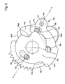
figure 1 représente, de façon schématisée, partielle et en plan, en vue de dessus pour lafigure 1A et de dessous pour lafigure 1B , un mécanisme d'arrêt sélectif de sonnerie selon l'invention, comportant un mobile d'isolement, pour une pièce d'horlogerie comportant des moyens moteurs et un mécanisme de contrôle de réserve de marche, dans un état d'armage maximal des moyens moteurs, correspondant à un fonctionnement complet des sonneries et du mouvement ; - la
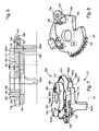
figure 2 représente, de façon schématisée, partielle et en plan, en vue de dessus pour lafigure 2A et de dessous pour lafigure 2B , le mécanisme de lafigure 2 , dans un état de désarmage partiel, où la sonnerie automatique est bloquée, et où le mouvement fonctionne ; - la
figure 3 représente, de façon schématisée, partielle et en plan, en vue de dessus pour lafigure 3A et de dessous pour lafigure 3B , le mécanisme de lafigure 2 , dans un état de désarmage partiel, où toutes les sonneries sont bloquées, et où le mouvement fonctionne ; - la
figure 4 représente, de façon schématisée, partielle et en plan, en vue de dessus pour lafigure 4A et de dessous pour lafigure 4B , le mécanisme de lafigure 2 , dans un état de désarmage complet, où toutes les sonneries sont bloquées, et où le mouvement est bloqué ; - la
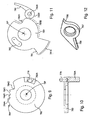
figure 5 représente, de façon schématisée et en plan, le mobile d'isolement selon l'invention ; - la
figure 6 représente, de façon schématisée et en coupe AA, le mobile de lafigure 5 ; - la
figure 7 représente, de façon schématisée et en perspective, le mobile de lafigure 5 ; - la
figure 8 représente, de façon schématisée et en perspective, une roue d'arrêtage de sonnerie que comporte le mobile de lafigure 5 ; - la
figure 9 représente, de façon schématisée et en perspective, une came d'arrêt de sonnerie que comporte le mobile de lafigure 5 ; - la
figure 10 représente, de façon schématisée et en coupe passant par son axe de pivotement et un tenon qu'elle comporte, la came de lafigure 10 ; - la
figure 11 représente, de façon schématisée et en perspective, une surprise d'arrêtage de mouvement que comporte le mobile de lafigure 5 ; - la
figure 12 représente, de façon schématisée et en perspective, une levée à deux becs que comporte le mobile de lafigure 5 ; - la
figure 13 représente, sous la forme d'un schéma-bloc, une pièce d'horlogerie comportant un mécanisme d'arrêt sélectif de sonnerie selon l'invention.
- the
figure 1 represents, schematically, partially and in plan, in plan view for theFigure 1A and from below for theFigure 1B , a selective ringing stop mechanism according to the invention, comprising an isolation mobile, for a timepiece comprising motor means and a power reserve control mechanism, in a state of maximal arming means motors, corresponding to a complete operation of ringing and movement; - the
figure 2 represents, schematically, partially and in plan, in plan view for theFigure 2A and from below for theFigure 2B , the mechanism of thefigure 2 in a partial disarm state, where the automatic bell is blocked, and the movement is functioning; - the
figure 3 represents, schematically, partially and in plan, in plan view for thefigure 3A and from below for thefigure 3B , the mechanism of thefigure 2 in a partial disarm state, where all ring tones are blocked, and the movement is functioning; - the
figure 4 represents, schematically, partially and in plan, in top view for theFigure 4A and from below for theFigure 4B , the mechanism of thefigure 2 in a complete disarm state, where all ringtones are blocked, and the movement is blocked; - the
figure 5 represents, schematically and in plan, the isolation device according to the invention; - the
figure 6 represents, in a schematic form and in section AA, the mobile of thefigure 5 ; - the
figure 7 represents, schematically and in perspective, the motive of thefigure 5 ; - the
figure 8 represents, schematically and in perspective, a ring arresting wheel that includes the mobile of thefigure 5 ; - the
figure 9 represents, schematically and in perspective, a ring arresting ring that includes the mobile of thefigure 5 ; - the
figure 10 represents, schematically and in section passing through its axis of pivoting and a tenon that it comprises, the cam of thefigure 10 ; - the
figure 11 represents, schematically and in perspective, a motion arresting surprise that the mobile of thefigure 5 ; - the
figure 12 represents, schematically and in perspective, a two-spout lift that includes the mobile of thefigure 5 ; - the
figure 13 represents, in the form of a block diagram, a timepiece comprising a selective ringing stop mechanism according to the invention.
L'invention concerne le domaine de l'horlogerie, et en particulier des pièces d'horlogerie portatives telles que montres ou similaires, dont la réserve d'énergie est limitée.The invention relates to the field of watchmaking, and in particular portable timepieces such as watches or the like, whose energy reserve is limited.
En particulier l'invention concerne les pièces d'horlogerie à complications, et notamment à sonneries, en raison des consommations d'énergie importantes effectuées par de telles complications.In particular, the invention relates to timepieces with complications, and particularly to ringing, because of the significant energy consumption made by such complications.
L'invention est décrite ici, de façon non limitative, pour une pièce d'horlogerie dont certaines complications sont des sonneries. Naturellement l'invention est utilisable de façon similaire pour gérer différentes fonctions ou complications consommatrices d'énergie, de façon à établir entre ces fonctions des priorités de survie, lors de la décroissance du potentiel énergétique disponible, tout en garantissant le retour de chaque fonction à un stade de repos, afin de garantir un redémarrage normal lors de la réalimentation en énergie de la pièce d'horlogerie concernée.The invention is described here, without limitation, for a timepiece whose some complications are ring tones. Naturally, the invention can be used in a similar manner to manage various energy consuming functions or complications, so as to establish between these functions survival priorities, when the available energy potential decreases, while guaranteeing the return of each function to a rest stage, to guarantee a normal restart during the energy supply of the timepiece concerned.
L'invention concerne un mécanisme 760 d'arrêt sélectif des sonneries d'une pièce d'horlogerie 1000 comportant un mécanisme de sonnerie 100, en fonction du couple moteur disponible. Cette pièce d'horlogerie comporte un mouvement 200, et des moyens moteurs 120, constitués par un barillet ou un ensemble de barillets, ou similaire.The invention relates to a
Cette pièce d'horlogerie 1000 comporte un mécanisme de commande de sonnerie 1, qui est agencé pour piloter ce mécanisme de sonnerie 100, et qui comporte un dispositif pour déclencher l'arrêt du mouvement 200 par action sur une bascule de commande ou similaire. L'invention est ici décrite dans une version où ce dispositif de commande d'arrêt du mouvement comporte comme point d'entrée une bascule de blocage 771, notamment de type stop-secondes dans l'exemple des figures.This
Le mécanisme 760 est agencé pour, directement ou indirectement, dans au moins une de ses positions de fonctionnement, interdire l'exécution d'une sonnerie, par blocage d'une levée de commande pour l'exécution d'une sonnerie, qui est, dans une variante non limitative, une levée de commande de marteau pour la percussion d'un timbre, gong ou similaire, ou d'un mécanisme sonore similaire de sonnerie ou de boîte à musique, ou bien par blocage direct d'un tel marteau ou similaire.The
Dans le cas où le mécanisme de sonnerie 100 comporte plusieurs modes de sonnerie, le mécanisme 760 est avantageusement agencé pour commander, de façon différée dans le temps, l'arrêt de certaines sonneries les unes par rapport aux autres.In the case where the
Le mécanisme 760 est encore agencé pour, directement ou indirectement, dans au moins une de ses positions de fonctionnement, bloquer le fonctionnement du mouvement par action de commande en pivotement de la bascule de blocage 771 ou du dispositif de commande d'arrêt du mouvement concerné.The
L'invention est ici plus précisément décrite, de façon nullement limitative, avec la commande d'une telle bascule de blocage 771.The invention is here more specifically described, in no way limiting, with the control of such a
L'invention permet à la pièce d'horlogerie de gérer, par l'intermédiaire de ce mécanisme 760, le couple disponible au niveau de ces moyens moteurs 120, en limitant ou non la marche des sonneries, que celles.ci soient armées ou non, ou encore en stoppant le mouvement 200 quand la réserve de marche est insuffisante pour assurer un fonctionnement correct. Ce mode de fonctionnement est utile pour une pièce d'horlogerie compliquée, car un tel arrêt commandé du mouvement ou des mécanismes de sonnerie permet de prévenir un arrêt intempestif en cours d'exécution, ou bien d'une sonnerie particulière, ou bien de l'exécution par le mouvement d'une complication particulière que comporte la pièce. L'invention permet ainsi de ramener chaque complication dans un mode de repos, avant son arrêt complet. Le redémarrage ultérieur est alors garanti, dans l'intégrité de toutes les fonctions, et aucun réglage ou décalage autre que la mise à l'heure n'est nécessaire lors du rechargement des moyens moteurs 120 pour le redémarrage de la pièce d'horlogerie.The invention allows the timepiece to manage, through this
L'invention est ainsi adaptée au contrôle d'une pièce d'horlogerie 1000 ou d'un mouvement 200 qui comporte un mécanisme de contrôle de réserve de marche 750, lequel comporte un arbre de sortie 751.The invention is thus adapted to the control of a
L'invention utilise une information relative à la réserve de marche disponible au niveau de ces moyens moteurs 120, constituée par la position angulaire de cet arbre de sortie 751, pour piloter un mécanisme de décrochement de tout ou partie des sonneries disponibles au niveau du mécanisme de sonnerie 100, ou de mise à l'arrêt du mouvement 200.The invention uses information relating to the power reserve available at these motor means 120, constituted by the position angular of this
L'information est réversible, puisque cet arbre de sortie 751 pivote dans un premier sens S1 lors du déchargement des moyens moteurs 120, et dans le sens inverse S2 lors de leur rechargement. Aussi le mécanisme 760 selon l'invention est-il conçu pour, lors du rechargement des moyens moteurs 120 par remontage ou similaire, pour libérer successivement les fonctions qu'il avait bloquées, dès que l'énergie suffisante à leur fonctionnement correct est à nouveau disponible.The information is reversible, since this
Cet arbre de sortie 751 supporte une came 752, qui coopère avec un palpeur 753 que comporte un mécanisme de transmission 755, pour commander, directement ou indirectement, le mouvement d'un râteau 756.This
La came 752 est de préférence, tel que représenté sur les figures, une came-escargot, de rayon à croissance sensiblement uniforme, le plus petit rayon correspondant à la position d'armage maximal des moyens moteurs 120 de la
Ce râteau 756 commande le pivotement d'un mobile d'isolement 770, que comporte le mécanisme d'arrêt sélectif 760, et qui est agencé pour commander la position de la bascule de blocage 771 en fonction de la position angulaire de l'arbre de sortie 751, et de façon préférée en agissant sur un bec 786 que comporte la bascule de blocage 771.This
Ce mobile d'isolement 770 comporte, superposées l'une à l'autre, et agencées pour pivoter autour d'un même axe de pivotement DP:
- une came d'arrêt de sonnerie 783 ;
- une roue d'arrêtage de sonnerie 745;
- une surprise d'arrêtage de mouvement 780.
- a
ring arresting cam 783; - a
ring arresting wheel 745; - a
stop motion surprise 780.
La came d'arrêt de sonnerie 783 comporte une pluralité d'encoches périphériques 784. Dans la variante particulière d'exécution illustrée par les figures, qui correspond à une utilisation pour un mécanisme de sonnerie 100 qui comporte plusieurs modes de sonnerie, qui sont commutables par action sur une tringlerie de commande, et en particulier un mode où toutes les sonneries fonctionnent en automatique ou sous commande manuelle d'un utilisateur, et un autre mode où les sonneries ne sont possibles qu'en automatique, ces encoches sont au nombre de quatre : 784A, 784B, 784C, 784D, tel que visible sur la
Chacune de ces encoches 784 est agencée pour coopérer, dans une position angulaire particulière de la came 783, avec un bec 795 que comporte un cliquet 789 poussé vers l'axe de pivotement DP par un ressort 791.Each of these
L'encoche 784A correspond au niveau minimal de réserve de marche, auquel l'arrêt du mouvement 200 doit être déclenché. L'encoche 784D correspond au niveau maximal de réserve de marche, où les moyens moteurs 120 sont au maximum de leur capacité, et où le mécanisme 760 n'exerce aucune action d'entrave, ni sur le mécanisme de sonnerie 100, ni sur le mouvement 200.The
Entre ces deux positions, les encoches intermédiaires, ici 784 C et 784B, correspondent à des positions où l'on choisit d'arrêter, respectivement, le fonctionnement de l'ensemble des sonneries automatiques, et le fonctionnement de toutes les sonneries y compris sur commande manuelle de l'utilisateur.Between these two positions, the intermediate notches, here 784 C and 784B, correspond to positions where one chooses to stop, respectively, the operation of all the automatic tones, and the operation of all the ringtones including on manual control of the user.
Cette came 783 est porteuse d'une goupille 778 sensiblement parallèle à son axe de pivotement DP, et saillant d'un côté supérieur d'un flasque sensiblement plan qui comporte à sa périphérie les encoches 784, pour coopérer avec les autres étages du mobile d'isolement 770.This
La came 783 comporte encore un tenon 783A saillant sensiblement parallèlement à son axe de pivotement DP et situé d'un côté inférieur opposé au côté supérieur de ce flasque.The
Ce tenon 783A est disposé de façon à venir s'insérer dans la chaîne cinématique de percussion d'un mécanisme de sonnerie 100, et notamment, dans l'exemple préféré de réalisation illustré par les figures, sur la trajectoire d'un marteau, entre ce marteau et un timbre ou similaire, selon la position angulaire de la came d'arrêt de sonnerie 783.This
Dans la position du bec 795 du cliquet 789 dans l'encoche 784C correspondant au blocage des sonneries automatiques, le tenon 783A est interposé entre un premier marteau de déclenchement propre à ces sonneries, non représenté sur les figures, et le timbre, ou similaire, correspondant.In the position of the
Dans la position du bec 795 du cliquet 789 dans l'encoche 784B correspondant au blocage de toutes les sonneries dont les sonneries déclenchées manuellement par l'utilisateur, le tenon 783A est encore interposé entre un second marteau de déclenchement propre à ces sonneries, non représenté sur les figures, et le timbre, ou similaire, correspondant.In the position of the
Quand le bec 795 occupe l'encoche 784A, le mécanisme 760 bloque le mouvement 200, comme il va être exposé plus loin.When the
La roue d'arrêtage de sonnerie 745 comporte un secteur denté externe 779, qui est agencé pour coopérer avec une denture 788 que comporte le râteau 756. Cette roue d'arrêtage de sonnerie 745 comporte une lumière oblongue 777, qui autorise un mouvement limité de la goupille 778 de la came 783, ce qui limite le pivotement relatif de la roue d'arrêtage de sonnerie 745 par rapport à la came d'arrêt de sonnerie 783.The
Au voisinage de cette lumière oblongue 777, la roue d'arrêtage de sonnerie 745 porte un pivot 747 de pivotement d'une levée à deux becs 797, laquelle comporte un premier bec 798 tourné vars l'axe de pivotement DP, et un deuxième bec 799 s'en éloignant sensiblement radialement.In the vicinity of this
La roue d'arrêtage de sonnerie 745 est porteuse d'un ressort 796 de rappel de la levée 797 dans une position tendant à réduire la position radiale extrême du deuxième bec 799, et tendant à faire pivoter la levée 797 dans le sens horaire sur la
Par ailleurs, la roue d'arrêtage de sonnerie 745 comporte, sur une de ses faces qui est, dans l'exemple illustré par les figures, une face inférieure qui est tournée vers la face supérieure de la came 783, un dégagement périphérique 758, entre un bras 756 et un bossage 757 comportant une face d'appui 746, ce bras 756 et ce bossage 757 encadrant la lumière oblongue 777. La face d'appui 746 constitue une surface de butée pour le deuxième bec 799 de la bascule à deux becs 797.Furthermore, the
La roue d'arrêtage de sonnerie 745 est, encore, porteuse d'une goupille 794 sensiblement parallèle à son axe de pivotement DP, qui est saillante du côté d'une face supérieure de la roue 745 opposée à sa face inférieure. Une extrémité du secteur denté 779 sert d'appui à un ressort de rappel 792, fixé sur la platine ou un pont du mouvement 200, et qui tend à faire pivoter ce secteur denté 779 dans le sens anti-horaire sur la
La levée 797, selon sa position, peut recouvrir partiellement la lumière 777, et constituer une butée pour la goupille 778.The
La surprise d'arrêtage de mouvement 780 comporte un bras pourvu d'une zone de fonction 781 A, représentée en pointillé sur la
Cette surprise 780 comporte une lumière oblongue 793, agencée pour autoriser le mouvement de la goupille 794 de la roue d'arrêtage de sonnerie 745, et qui limite le pivotement relatif entre la roue d'arrêtage de sonnerie 745 et la surprise d'arrêtage de mouvement 780.This
Cette surprise d'arrêtage de mouvement 780 comporte encore une zone de roulement 780B périphérique, représentée en trait interrompu sur la
Le mécanisme 760 d'arrêt sélectif comporte encore une pièce dentée 772, fixée sur la platine ou un pont du mouvement 200, et qui comporte une première dent 773 et une deuxième dent 774, qui sont toutes deux situées sur la trajectoire du deuxième bec 798 de la levée 797, quand celle-ci est dans son extension radiale maximale. L'écart entre cette première dent 773 et cette deuxième dent 774 est voisin de l'écart des positions extrêmes que peut occuper la goupille 778 dans la lumière 777 de la roue d'arrêtage de sonnerie 745.The
De préférence, les extrémités d'extension radiale maximale de ces dents 773 et 774 vers l'axe de pivotement DP sont situées sur un même rayon RE.Preferably, the ends of maximum radial extension of these
La position de désarmement complet des moyens moteurs 120 correspond à la coopération de l'encoche 784A de la came d'arrêt de sonnerie 783 avec le bec 795 du cliquet 789.The complete disarming position of the motor means 120 corresponds to the engagement of the
A ce stade, le tenon 783A bloque toute sonnerie, et le secteur denté 788 du râteau 756 est en position d'éloignement maximal du mobile d'isolement 770.At this stage, the
Quand on commence à recharger les moyens moteurs 120, on déplace le râteau 756 en le rapprochant du mobile 770, dans le sens A sur la
Ce mouvement fait pivoter le secteur denté 779 de la roue 745.This movement rotates the
Le ressort 790 est agencé de façon à ne se déformer que très peu au flambage, il tend alors à pousser le galet 790B, depuis la surface de roulement 780B dans l'encoche 780A, et ainsi à faire pivoter la surprise 780 dans le sens horaire de la
La poursuite de la course du râteau 756 et du secteur 779 fait pivoter celui-ci dans le sens anti-horaire sur la
La surprise 780 étant bloquée en position par action du galet 790B dans l'encoche 780A, la course de pivotement possible de la roue 745 par rapport à cette position fixe de la surprise 780 est limité par le débattement de la goupille 794 de la roue 745 dans la lumière oblongue 793 de la surprise 780.The
Cette course angulaire réduite permet au premier bec 798 de la levée 797, qui tend à pivoter dans le sens anti-horaire de la
Le passage de chacune de ses deux dents 773 et 774 oblige la levée 797 à pivoter autour de son axe de pivot 747, pour permettre au premier bec 798 de prendre une position dans laquelle son extension radiale maximale est inférieure au rayon RE. Le deuxième bec 799 doit alors pousser la goupille 770, et ainsi faire pivoter la came 783, pour aller occuper une nouvelle position sur une autre des encoches 784, en l'occurrence 784B quand le premier bec 798 franchit la première dent 773, et 784C quand il franchit la deuxième dent 774. Le ressort 796 rétablit le premier bec 798 dans son extension maximale après le passage de chacune des dents 773 et 774.The passage of each of its two
Lors de l'armage complet des moyens moteurs 120, le pivotement maximal de la roue 745 entraîne la goupille 778 de la came 783, et fait passer celle-ci dans la position angulaire où l'encoche 784D coopère avec le bec 795 du cliquet 789.During the complete arming of the motor means 120, the maximum pivoting of the
En fonctionnement inverse, le désarmage des moyens moteurs 120 se traduit par un mouvement du râteau 756 dans le sens B de la
Le bec 795 du cliquet 789 est alors dans l'encoche 784D, qui est la plus profonde.The
Le galet 790B du ressort 790 roule alors sur la surface de roulement 780B.The 790B roller of the 790 spring then rolls on the running
Le bec 786 de la bascule de blocage 771 est à distance de la face d'appui 781 de la surprise, et fait face à celle-ci.The
La roue 745 pivote alors dans le sens horaire sur la
Tel que visible sur les
La position de franchissement de la deuxième dent 774 correspond à la position du bec 795 du cliquet 789 dans l'encoche 784C correspondant au blocage des sonneries automatiques, et conduit au blocage, par le tenon 783A de la came 783, du premier marteau de déclenchement propre à ces sonneries, et le timbre, ou similaire, correspondant.The crossing position of the
La
Le premier bec 798 est entre la deuxième dent 774 et la première dent 773.The
Le bec 795 du cliquet 789 est dans l'encoche 784C, et le marteau 531 est ainsi bloqué.The
Le galet 790B du ressort 790 roule toujours sur la surface de roulement 780B.The 790B roller from the 790 spring still rolls on the 780B running surface.
Le bec 786 de la bascule de blocage 771 se rapproche de la face d'appui 781 de la surprise 780.The
La
Le passage de la première dent 773 correspond à la position du bec 795 du cliquet 789 dans l'encoche 784B correspondant au blocage des sonneries dont les sonneries déclenchées manuellement par l'utilisateur, le tenon 783A est encore interposé entre un second marteau de déclenchement propre à ces sonneries, et le timbre, ou similaire, correspondant.The passage of the
Le galet 790B du ressort 790 roule toujours sur la surface de roulement 780B, et approche de l'encoche 784A.The 790B roller of the 790 spring still rolls on the running
Le bec 786 de la bascule de blocage 771 se rapproche et vient au contact de la face d'appui 781 de la surprise 780.The
La
Après le franchissement de la première dent 773, et en fin de désarmage des moyens moteurs 120, le galet 790B du ressort 790 pénètre brutalement dans l'encoche 780A, et la surface d'appui 781 de la surprise 780 agit alors sur le bec 786 de la bascule de blocage 771, qui monte sur la zone de fonction 781 A, pour commander le blocage du mouvement 200.After crossing the
Claims (10)
- Timepiece (1000) including a drive means (120), a movement (200), a mechanism (750) for controlling the power reserve of said drive means (120) which includes an output arbour (751) whose angular position indicates the power reserve available in said drive means (120), a striking mechanism (100) controlled by a striking mechanism control mechanism (1), which includes a locking lever (771) for locking said movement (200), said timepiece further including, inserted between said output arbour (751) and said locking lever (771), a selective stopping mechanism (760), for selectively stopping the strikes of said timepiece (1000), according to the drive torque available in said drive means (120), said selective stopping mechanism (760) being arranged to manage the available torque in said drive means (120) by limiting or not limiting the working of the strikes, according to said angular position of said output arbour (751), to control a mechanism for uncoupling all or part of the available striking works in said striking mechanism (100), via a transmission mechanism (755) controlling an isolating wheel set (770), which is comprised in said selective stopping mechanism (760) and arranged to control the position of said locking lever (771) and further arranged to release or prevent the movement of a striking mechanism control rod linkage (700) and/or to allow or prevent the strike of a hammer against a gong.
- Timepiece (1000) according to claim 1, characterized in that said selective stopping mechanism (760) includes, arranged to pivot with said output arbour (751), a cam (752), which cooperates with a feeler spindle (753) comprised in said transmission mechanism (755) for controlling, directly or indirectly, the movement of a rack (756), which controls the pivoting of an input stage of said isolating wheel set (770), wherein said isolating wheel set (770) includes a striking mechanism stop cam (783), a striking mechanism stop wheel (745), and a surprise-piece for stopping the movement (780), which are superposed on each other and arranged to pivot about a same pivot axis (DP), according to angular clearances that are limited in relation to each other, and acting against or by the action of elastic return means, and to control the movement of an output stage formed by a surprise-piece (780) for stopping the movement, wherein a bearing surface (781) and an operating area (781A) connected to each other are arranged to cooperate with said locking lever (771) by respectively forming a stop member and a ramp for said locking lever (771).
- Timepiece (1000) according to claim 2, characterized in that said selective stopping mechanism (760) includes, mounted externally to said isolating wheel set (770), a toothed part (772) including at least a first tooth (773) and a second tooth (774), projecting substantially radially towards said pivot axis (DP) and the ends of which are located on the same first radius (RE) relative to said pivot axis (DP) and in at first angular distance relative thereto, and in that said input stage includes, on the one hand, a toothed sector (779) arranged to cooperate additionally with said rack (756) to control the pivoting thereof, and on the other hand, a plate (545) carrying a lifting piece (797) with two beaks pivoting off-centre relative to said pivot axis (DP), said lifting piece (797) including a first beak (798) projecting substantially radially relative to said pivot axis (DP) opposite thereto and the end of which is movable between two positions whose radius relative to said pivot axis (DP) is respectively smaller and greater than said first radius (RE).
- Timepiece (1000) according to claim 3, characterized in that said lifting piece (797) with two beaks includes a second beak (799) substantially radially relative to said pivot axis (DP) and turned towards said axis, and in that said isolating wheel set (770) further includes a cam (783) which pivots relative to said pivot axis (DP) and which carries a pin (778) substantially parallel to said pivot axis (DP), said pin (778) having limited mobility in a hole (777) comprised in said plate (545) angularly relative to said pivot axis (DP), against said second beak (799) which is pushed towards said pin (778) by elastic return means (796).
- Timepiece (1000) according to claim 4, characterized in that said cam (783) includes a plurality of peripheral notches (784A; 784B; 784C; 784D), which are each arranged to cooperate, in a particular angular position of said cam (783), with a beak (795) comprised in an arm-click (789) pushed towards said cam (783) by elastic return means (791).
- Timepiece (1000) according to claim 3, characterized in that said input stage carries a pin (794) substantially parallel to the pivot axis (DP) thereof and which has limited mobility in a hole (793) in said movement stop surprise-piece (780) angularly relative to said pivot axis (DP) to limit the relative angular clearance between said movement stop surprise-piece (780) and said striking mechanism stop wheel (745).
- Timepiece (1000) according to claim 3, characterized in that said toothed sector (779) includes an end which is used as support for elastic return means (792) which tend to move said toothed sector (779) away from said rack (756).
- Timepiece (1000) according to claim 2, characterized in that said movement stop surprise-piece (780) includes a peripheral rolling surface (780B), connected to a notch (780A), both arranged to cooperate with a roller (790B) pivotally mounted at one end of a spring (790) subjected to a substantially radial movement relative to said pivot axis (DP).
- Timepiece (1000) according to claim 4, characterized in that said cam (783) includes a stud (783A) which, according to the angular position of said cam (783), prevents or allows the strike of at least one hammer on a gong, by being placed or not being placed between said hammer or gong.
- Timepiece (1000) according to claims 5 and 9, characterized in that, in one position of said beak (795) in one said notch (784C) for locking the automatic striking mechanisms, said stud (783A) is inserted between a first release hammer peculiar to said striking mechanisms and the corresponding gong, and in that, in one position of said beak (795) in one said notch (784B) for locking all the striking mechanisms which are manually released by the user, said stud (783A) is again inserted between a second release hammer peculiar to said striking mechanisms and the corresponding gong.
Priority Applications (5)
| Application Number | Priority Date | Filing Date | Title |
|---|---|---|---|
| EP11159238.2A EP2503405B1 (en) | 2011-03-22 | 2011-03-22 | Timepiece comprising a striking mechanism and a mechanism for selectively stopping said striking mechanism. |
| CH00484/11A CH704672A2 (en) | 2011-03-22 | 2011-03-22 | Selective stop mechanism for striking work of watch, has isolation mobile for controlling position of blocking lever and releasing/prohibiting movement of striking work control rod and/or authorizing/prohibiting impact of hammer on gong |
| US13/424,603 US8730768B2 (en) | 2011-03-22 | 2012-03-20 | Mechanism for selectively stopping the striking mechanisms of a timepiece according to the available drive torque |
| CN201210077869.7A CN102692859B (en) | 2011-03-22 | 2012-03-22 | Mechanism for selectively stopping the striking mechanism of a timepiece according to the available motor torque |
| JP2012065122A JP5537584B2 (en) | 2011-03-22 | 2012-03-22 | A watch that can selectively stop the striking mechanism with available drive torque |
Applications Claiming Priority (1)
| Application Number | Priority Date | Filing Date | Title |
|---|---|---|---|
| EP11159238.2A EP2503405B1 (en) | 2011-03-22 | 2011-03-22 | Timepiece comprising a striking mechanism and a mechanism for selectively stopping said striking mechanism. |
Publications (2)
| Publication Number | Publication Date |
|---|---|
| EP2503405A1 EP2503405A1 (en) | 2012-09-26 |
| EP2503405B1 true EP2503405B1 (en) | 2014-07-30 |
Family
ID=44680985
Family Applications (1)
| Application Number | Title | Priority Date | Filing Date |
|---|---|---|---|
| EP11159238.2A Active EP2503405B1 (en) | 2011-03-22 | 2011-03-22 | Timepiece comprising a striking mechanism and a mechanism for selectively stopping said striking mechanism. |
Country Status (5)
| Country | Link |
|---|---|
| US (1) | US8730768B2 (en) |
| EP (1) | EP2503405B1 (en) |
| JP (1) | JP5537584B2 (en) |
| CN (1) | CN102692859B (en) |
| CH (1) | CH704672A2 (en) |
Cited By (1)
| Publication number | Priority date | Publication date | Assignee | Title |
|---|---|---|---|---|
| EP3435169A1 (en) | 2017-07-25 | 2019-01-30 | Blancpain SA | Halting mechanism for a timepiece chiming mechanism |
Families Citing this family (12)
| Publication number | Priority date | Publication date | Assignee | Title |
|---|---|---|---|---|
| US8995238B2 (en) * | 2013-03-28 | 2015-03-31 | Rolex S.A. | Device for displaying time information |
| CN104656409B (en) * | 2013-11-19 | 2017-04-19 | 天津海鸥表业集团有限公司 | Pointer fly-back type hour indicating mechanism with safety structure |
| DE102014115642B3 (en) * | 2014-10-28 | 2015-11-05 | Lange Uhren Gmbh | Clock |
| CN106292246B (en) * | 2015-05-14 | 2018-06-26 | 天津海鸥表业集团有限公司 | Automatic time-telling starting control structure in mechanical watch |
| EP3306416B1 (en) * | 2016-10-04 | 2019-08-21 | ETA SA Manufacture Horlogère Suisse | Mechanical clock movement with power-reserve detection |
| EP3306415B1 (en) * | 2016-10-04 | 2020-05-20 | ETA SA Manufacture Horlogère Suisse | Mechanical clock movement with power-reserve detection |
| JP6740323B2 (en) * | 2017-07-25 | 2020-08-12 | ブランパン・エス アー | Torque smoothing for timers, especially timers with a strike mechanism |
| EP3435174B1 (en) * | 2017-07-25 | 2021-06-16 | Blancpain SA | Chime mode selector for watch or timepiece |
| EP3502801B1 (en) * | 2017-12-19 | 2021-02-17 | Omega SA | Chronograph repetition mechanism with safety |
| EP3502802B1 (en) * | 2017-12-19 | 2021-02-17 | Omega SA | Chronograph repetition mechanism with safety |
| EP3575886B1 (en) * | 2018-05-28 | 2021-03-10 | Blancpain SA | Timepiece with striking mechanism and safety trigger |
| EP3968094A1 (en) | 2020-09-09 | 2022-03-16 | Omega SA | Timepiece selector mechanism |
Family Cites Families (10)
| Publication number | Priority date | Publication date | Assignee | Title |
|---|---|---|---|---|
| EP1708051A1 (en) | 2005-03-31 | 2006-10-04 | Zenith International SA | Timepiece comprising an alarm |
| ATE395639T1 (en) * | 2005-03-31 | 2008-05-15 | Zenith Internat Sa | REPEATING WATCH WITH A MINUTE REPEATING MECHANISM |
| EP1760545A1 (en) * | 2005-09-01 | 2007-03-07 | Montres Journe S.A. | Timepiece with a striking mechanism |
| EP1925995B1 (en) * | 2006-11-21 | 2014-06-18 | Christophe Claret Engineering S.A. | Chiming mechanism |
| EP1925997B1 (en) * | 2006-11-21 | 2013-02-27 | Manufacture Claret SA | Chiming mechanism |
| EP2073076B1 (en) * | 2007-12-20 | 2012-06-13 | Montres Breguet S.A. | Alarm clock control mechanism |
| EP2133758A1 (en) * | 2008-06-12 | 2009-12-16 | Blancpain S.A. | Timepiece with a striking mechanism |
| EP2226688B1 (en) * | 2009-03-05 | 2011-09-07 | Vaucher Manufacture Fleurier S.A. | Timepiece |
| CH700849A1 (en) * | 2009-04-28 | 2010-10-29 | Frank Mueller Watchland S A | Timepiece. |
| CH701257B1 (en) * | 2009-06-11 | 2014-01-31 | Richemont Int Sa | striking mechanism for a timepiece. |
-
2011
- 2011-03-22 EP EP11159238.2A patent/EP2503405B1/en active Active
- 2011-03-22 CH CH00484/11A patent/CH704672A2/en not_active Application Discontinuation
-
2012
- 2012-03-20 US US13/424,603 patent/US8730768B2/en active Active
- 2012-03-22 JP JP2012065122A patent/JP5537584B2/en active Active
- 2012-03-22 CN CN201210077869.7A patent/CN102692859B/en active Active
Cited By (1)
| Publication number | Priority date | Publication date | Assignee | Title |
|---|---|---|---|---|
| EP3435169A1 (en) | 2017-07-25 | 2019-01-30 | Blancpain SA | Halting mechanism for a timepiece chiming mechanism |
Also Published As
| Publication number | Publication date |
|---|---|
| US20120243385A1 (en) | 2012-09-27 |
| CN102692859B (en) | 2014-11-12 |
| CH704672A2 (en) | 2012-09-28 |
| EP2503405A1 (en) | 2012-09-26 |
| JP2012198212A (en) | 2012-10-18 |
| JP5537584B2 (en) | 2014-07-02 |
| US8730768B2 (en) | 2014-05-20 |
| CN102692859A (en) | 2012-09-26 |
Similar Documents
| Publication | Publication Date | Title |
|---|---|---|
| EP2503405B1 (en) | Timepiece comprising a striking mechanism and a mechanism for selectively stopping said striking mechanism. | |
| EP1798611B1 (en) | Timepiece including a striking mechanism with instant triggering | |
| EP1970778B1 (en) | Timepiece comprising a device indicating the power reserve | |
| EP1798610B1 (en) | Timepiece including a single-pawl striking mechanism | |
| EP3001258B1 (en) | Ringing mechanism with differentiated ringtones | |
| EP2498147B1 (en) | Ringer block and wake-up alarm drive mechanism for ringing timepiece | |
| EP2498143B1 (en) | Isolation mechanism between timepiece mechanisms for setting off different acoustic signals | |
| CH704591B1 (en) | striking mechanism minute repeater with a safety mechanism against accidental manipulation. | |
| EP1708050A1 (en) | Timepiece with a minute-repeater mechanism | |
| EP2498149B1 (en) | Duration limiter mechanism for timepiece mechanism | |
| CH704625A2 (en) | Secondary strike release mechanism i.e. alarm mechanism, for use in striking or grand strike or minute repeater mechanism of e.g. wristwatch, has coupling mechanism releasing striking mechanism acoustic signal by coupling repeater mechanism | |
| EP2503411A1 (en) | Single-ratchet instant perpetual calendar | |
| EP3435169B1 (en) | Halting mechanism for a timepiece chiming mechanism | |
| EP2363765B1 (en) | Device for sequentially controlling at least two lifts of a timepiece mechanism | |
| CH703361A2 (en) | Movement clock having chronograph functions and account-a-down. | |
| EP3108307B1 (en) | Striking mechanism for a clock piece | |
| EP3489765A1 (en) | Watch with chiming mechanism with regulator and time-setting protection | |
| EP3575886B1 (en) | Timepiece with striking mechanism and safety trigger | |
| EP3361323B1 (en) | Winding system of a timepiece | |
| CH704590A2 (en) | Mechanism for isolating clock mechanism and sound signal releasing mechanism of e.g. wristwatch, has isolator engaging with control mechanism to authorize passage of sensors for being in contact with time reference in disarming position | |
| CH715723B1 (en) | Instant jump mechanism of a display mobile. | |
| CH698598B1 (en) | Timepiece e.g. grand strike watch, has toggle lever pivotably coupled to release lever during automatic release, where manual release is caused by pivoting of toggle lever relative to release lever via action of manual control member | |
| EP3489762B1 (en) | Operating system for a timepiece | |
| EP4312087A1 (en) | Annual calendar mechanism for timepiece movement | |
| CH715027B1 (en) | Timepiece with striking mechanism and release safety device. |
Legal Events
| Date | Code | Title | Description |
|---|---|---|---|
| PUAI | Public reference made under article 153(3) epc to a published international application that has entered the european phase |
Free format text: ORIGINAL CODE: 0009012 |
|
| AK | Designated contracting states |
Kind code of ref document: A1 Designated state(s): AL AT BE BG CH CY CZ DE DK EE ES FI FR GB GR HR HU IE IS IT LI LT LU LV MC MK MT NL NO PL PT RO RS SE SI SK SM TR |
|
| AX | Request for extension of the european patent |
Extension state: BA ME |
|
| 17P | Request for examination filed |
Effective date: 20130326 |
|
| RIC1 | Information provided on ipc code assigned before grant |
Ipc: G04B 9/02 20060101AFI20131008BHEP |
|
| GRAP | Despatch of communication of intention to grant a patent |
Free format text: ORIGINAL CODE: EPIDOSNIGR1 |
|
| INTG | Intention to grant announced |
Effective date: 20131220 |
|
| GRAP | Despatch of communication of intention to grant a patent |
Free format text: ORIGINAL CODE: EPIDOSNIGR1 |
|
| INTG | Intention to grant announced |
Effective date: 20140429 |
|
| GRAJ | Information related to disapproval of communication of intention to grant by the applicant or resumption of examination proceedings by the epo deleted |
Free format text: ORIGINAL CODE: EPIDOSDIGR1 |
|
| INTG | Intention to grant announced |
Effective date: 20140507 |
|
| GRAP | Despatch of communication of intention to grant a patent |
Free format text: ORIGINAL CODE: EPIDOSNIGR1 |
|
| GRAS | Grant fee paid |
Free format text: ORIGINAL CODE: EPIDOSNIGR3 |
|
| GRAA | (expected) grant |
Free format text: ORIGINAL CODE: 0009210 |
|
| INTG | Intention to grant announced |
Effective date: 20140606 |
|
| AK | Designated contracting states |
Kind code of ref document: B1 Designated state(s): AL AT BE BG CH CY CZ DE DK EE ES FI FR GB GR HR HU IE IS IT LI LT LU LV MC MK MT NL NO PL PT RO RS SE SI SK SM TR |
|
| REG | Reference to a national code |
Ref country code: GB Ref legal event code: FG4D Free format text: NOT ENGLISH |
|
| REG | Reference to a national code |
Ref country code: CH Ref legal event code: EP |
|
| REG | Reference to a national code |
Ref country code: AT Ref legal event code: REF Ref document number: 680253 Country of ref document: AT Kind code of ref document: T Effective date: 20140815 |
|
| REG | Reference to a national code |
Ref country code: IE Ref legal event code: FG4D Free format text: LANGUAGE OF EP DOCUMENT: FRENCH |
|
| REG | Reference to a national code |
Ref country code: DE Ref legal event code: R096 Ref document number: 602011008672 Country of ref document: DE Effective date: 20140911 |
|
| REG | Reference to a national code |
Ref country code: CH Ref legal event code: NV Representative=s name: ICB INGENIEURS CONSEILS EN BREVETS SA, CH |
|
| REG | Reference to a national code |
Ref country code: AT Ref legal event code: MK05 Ref document number: 680253 Country of ref document: AT Kind code of ref document: T Effective date: 20140730 |
|
| REG | Reference to a national code |
Ref country code: NL Ref legal event code: VDEP Effective date: 20140730 |
|
| REG | Reference to a national code |
Ref country code: LT Ref legal event code: MG4D |
|
| PG25 | Lapsed in a contracting state [announced via postgrant information from national office to epo] |
Ref country code: GR Free format text: LAPSE BECAUSE OF FAILURE TO SUBMIT A TRANSLATION OF THE DESCRIPTION OR TO PAY THE FEE WITHIN THE PRESCRIBED TIME-LIMIT Effective date: 20141031 Ref country code: SE Free format text: LAPSE BECAUSE OF FAILURE TO SUBMIT A TRANSLATION OF THE DESCRIPTION OR TO PAY THE FEE WITHIN THE PRESCRIBED TIME-LIMIT Effective date: 20140730 Ref country code: NO Free format text: LAPSE BECAUSE OF FAILURE TO SUBMIT A TRANSLATION OF THE DESCRIPTION OR TO PAY THE FEE WITHIN THE PRESCRIBED TIME-LIMIT Effective date: 20141030 Ref country code: PT Free format text: LAPSE BECAUSE OF FAILURE TO SUBMIT A TRANSLATION OF THE DESCRIPTION OR TO PAY THE FEE WITHIN THE PRESCRIBED TIME-LIMIT Effective date: 20141202 Ref country code: LT Free format text: LAPSE BECAUSE OF FAILURE TO SUBMIT A TRANSLATION OF THE DESCRIPTION OR TO PAY THE FEE WITHIN THE PRESCRIBED TIME-LIMIT Effective date: 20140730 Ref country code: BG Free format text: LAPSE BECAUSE OF FAILURE TO SUBMIT A TRANSLATION OF THE DESCRIPTION OR TO PAY THE FEE WITHIN THE PRESCRIBED TIME-LIMIT Effective date: 20141030 Ref country code: ES Free format text: LAPSE BECAUSE OF FAILURE TO SUBMIT A TRANSLATION OF THE DESCRIPTION OR TO PAY THE FEE WITHIN THE PRESCRIBED TIME-LIMIT Effective date: 20140730 Ref country code: FI Free format text: LAPSE BECAUSE OF FAILURE TO SUBMIT A TRANSLATION OF THE DESCRIPTION OR TO PAY THE FEE WITHIN THE PRESCRIBED TIME-LIMIT Effective date: 20140730 |
|
| PG25 | Lapsed in a contracting state [announced via postgrant information from national office to epo] |
Ref country code: PL Free format text: LAPSE BECAUSE OF FAILURE TO SUBMIT A TRANSLATION OF THE DESCRIPTION OR TO PAY THE FEE WITHIN THE PRESCRIBED TIME-LIMIT Effective date: 20140730 Ref country code: NL Free format text: LAPSE BECAUSE OF FAILURE TO SUBMIT A TRANSLATION OF THE DESCRIPTION OR TO PAY THE FEE WITHIN THE PRESCRIBED TIME-LIMIT Effective date: 20140730 Ref country code: CY Free format text: LAPSE BECAUSE OF FAILURE TO SUBMIT A TRANSLATION OF THE DESCRIPTION OR TO PAY THE FEE WITHIN THE PRESCRIBED TIME-LIMIT Effective date: 20140730 Ref country code: IS Free format text: LAPSE BECAUSE OF FAILURE TO SUBMIT A TRANSLATION OF THE DESCRIPTION OR TO PAY THE FEE WITHIN THE PRESCRIBED TIME-LIMIT Effective date: 20141130 Ref country code: HR Free format text: LAPSE BECAUSE OF FAILURE TO SUBMIT A TRANSLATION OF THE DESCRIPTION OR TO PAY THE FEE WITHIN THE PRESCRIBED TIME-LIMIT Effective date: 20140730 Ref country code: LV Free format text: LAPSE BECAUSE OF FAILURE TO SUBMIT A TRANSLATION OF THE DESCRIPTION OR TO PAY THE FEE WITHIN THE PRESCRIBED TIME-LIMIT Effective date: 20140730 Ref country code: AT Free format text: LAPSE BECAUSE OF FAILURE TO SUBMIT A TRANSLATION OF THE DESCRIPTION OR TO PAY THE FEE WITHIN THE PRESCRIBED TIME-LIMIT Effective date: 20140730 Ref country code: RS Free format text: LAPSE BECAUSE OF FAILURE TO SUBMIT A TRANSLATION OF THE DESCRIPTION OR TO PAY THE FEE WITHIN THE PRESCRIBED TIME-LIMIT Effective date: 20140730 |
|
| PG25 | Lapsed in a contracting state [announced via postgrant information from national office to epo] |
Ref country code: CZ Free format text: LAPSE BECAUSE OF FAILURE TO SUBMIT A TRANSLATION OF THE DESCRIPTION OR TO PAY THE FEE WITHIN THE PRESCRIBED TIME-LIMIT Effective date: 20140730 Ref country code: EE Free format text: LAPSE BECAUSE OF FAILURE TO SUBMIT A TRANSLATION OF THE DESCRIPTION OR TO PAY THE FEE WITHIN THE PRESCRIBED TIME-LIMIT Effective date: 20140730 Ref country code: SK Free format text: LAPSE BECAUSE OF FAILURE TO SUBMIT A TRANSLATION OF THE DESCRIPTION OR TO PAY THE FEE WITHIN THE PRESCRIBED TIME-LIMIT Effective date: 20140730 Ref country code: IT Free format text: LAPSE BECAUSE OF FAILURE TO SUBMIT A TRANSLATION OF THE DESCRIPTION OR TO PAY THE FEE WITHIN THE PRESCRIBED TIME-LIMIT Effective date: 20140730 Ref country code: RO Free format text: LAPSE BECAUSE OF FAILURE TO SUBMIT A TRANSLATION OF THE DESCRIPTION OR TO PAY THE FEE WITHIN THE PRESCRIBED TIME-LIMIT Effective date: 20140730 Ref country code: DK Free format text: LAPSE BECAUSE OF FAILURE TO SUBMIT A TRANSLATION OF THE DESCRIPTION OR TO PAY THE FEE WITHIN THE PRESCRIBED TIME-LIMIT Effective date: 20140730 |
|
| REG | Reference to a national code |
Ref country code: DE Ref legal event code: R097 Ref document number: 602011008672 Country of ref document: DE |
|
| PLBE | No opposition filed within time limit |
Free format text: ORIGINAL CODE: 0009261 |
|
| STAA | Information on the status of an ep patent application or granted ep patent |
Free format text: STATUS: NO OPPOSITION FILED WITHIN TIME LIMIT |
|
| 26N | No opposition filed |
Effective date: 20150504 |
|
| PG25 | Lapsed in a contracting state [announced via postgrant information from national office to epo] |
Ref country code: LU Free format text: LAPSE BECAUSE OF FAILURE TO SUBMIT A TRANSLATION OF THE DESCRIPTION OR TO PAY THE FEE WITHIN THE PRESCRIBED TIME-LIMIT Effective date: 20150322 Ref country code: MC Free format text: LAPSE BECAUSE OF FAILURE TO SUBMIT A TRANSLATION OF THE DESCRIPTION OR TO PAY THE FEE WITHIN THE PRESCRIBED TIME-LIMIT Effective date: 20140730 |
|
| PG25 | Lapsed in a contracting state [announced via postgrant information from national office to epo] |
Ref country code: SI Free format text: LAPSE BECAUSE OF FAILURE TO SUBMIT A TRANSLATION OF THE DESCRIPTION OR TO PAY THE FEE WITHIN THE PRESCRIBED TIME-LIMIT Effective date: 20140730 |
|
| REG | Reference to a national code |
Ref country code: IE Ref legal event code: MM4A |
|
| PG25 | Lapsed in a contracting state [announced via postgrant information from national office to epo] |
Ref country code: IE Free format text: LAPSE BECAUSE OF NON-PAYMENT OF DUE FEES Effective date: 20150322 |
|
| REG | Reference to a national code |
Ref country code: FR Ref legal event code: PLFP Year of fee payment: 6 |
|
| PG25 | Lapsed in a contracting state [announced via postgrant information from national office to epo] |
Ref country code: MT Free format text: LAPSE BECAUSE OF FAILURE TO SUBMIT A TRANSLATION OF THE DESCRIPTION OR TO PAY THE FEE WITHIN THE PRESCRIBED TIME-LIMIT Effective date: 20140730 |
|
| REG | Reference to a national code |
Ref country code: FR Ref legal event code: PLFP Year of fee payment: 7 |
|
| PG25 | Lapsed in a contracting state [announced via postgrant information from national office to epo] |
Ref country code: SM Free format text: LAPSE BECAUSE OF FAILURE TO SUBMIT A TRANSLATION OF THE DESCRIPTION OR TO PAY THE FEE WITHIN THE PRESCRIBED TIME-LIMIT Effective date: 20140730 Ref country code: HU Free format text: LAPSE BECAUSE OF FAILURE TO SUBMIT A TRANSLATION OF THE DESCRIPTION OR TO PAY THE FEE WITHIN THE PRESCRIBED TIME-LIMIT; INVALID AB INITIO Effective date: 20110322 |
|
| PG25 | Lapsed in a contracting state [announced via postgrant information from national office to epo] |
Ref country code: BE Free format text: LAPSE BECAUSE OF NON-PAYMENT OF DUE FEES Effective date: 20150331 |
|
| PG25 | Lapsed in a contracting state [announced via postgrant information from national office to epo] |
Ref country code: TR Free format text: LAPSE BECAUSE OF FAILURE TO SUBMIT A TRANSLATION OF THE DESCRIPTION OR TO PAY THE FEE WITHIN THE PRESCRIBED TIME-LIMIT Effective date: 20140730 |
|
| REG | Reference to a national code |
Ref country code: FR Ref legal event code: PLFP Year of fee payment: 8 |
|
| PG25 | Lapsed in a contracting state [announced via postgrant information from national office to epo] |
Ref country code: MK Free format text: LAPSE BECAUSE OF FAILURE TO SUBMIT A TRANSLATION OF THE DESCRIPTION OR TO PAY THE FEE WITHIN THE PRESCRIBED TIME-LIMIT Effective date: 20140730 |
|
| PG25 | Lapsed in a contracting state [announced via postgrant information from national office to epo] |
Ref country code: AL Free format text: LAPSE BECAUSE OF FAILURE TO SUBMIT A TRANSLATION OF THE DESCRIPTION OR TO PAY THE FEE WITHIN THE PRESCRIBED TIME-LIMIT Effective date: 20140730 |
|
| PGFP | Annual fee paid to national office [announced via postgrant information from national office to epo] |
Ref country code: FR Payment date: 20230222 Year of fee payment: 13 |
|
| PGFP | Annual fee paid to national office [announced via postgrant information from national office to epo] |
Ref country code: GB Payment date: 20230222 Year of fee payment: 13 Ref country code: DE Payment date: 20230221 Year of fee payment: 13 |
|
| P01 | Opt-out of the competence of the unified patent court (upc) registered |
Effective date: 20230611 |
|
| PGFP | Annual fee paid to national office [announced via postgrant information from national office to epo] |
Ref country code: CH Payment date: 20230401 Year of fee payment: 13 |