EP3572289B1 - Anordnungsstruktur einer fahrzeughilfsmaschine - Google Patents
Anordnungsstruktur einer fahrzeughilfsmaschine Download PDFInfo
- Publication number
- EP3572289B1 EP3572289B1 EP18757666.5A EP18757666A EP3572289B1 EP 3572289 B1 EP3572289 B1 EP 3572289B1 EP 18757666 A EP18757666 A EP 18757666A EP 3572289 B1 EP3572289 B1 EP 3572289B1
- Authority
- EP
- European Patent Office
- Prior art keywords
- auxiliary machine
- vehicular
- bracket
- harness
- vertical wall
- Prior art date
- Legal status (The legal status is an assumption and is not a legal conclusion. Google has not performed a legal analysis and makes no representation as to the accuracy of the status listed.)
- Active
Links
- NJPPVKZQTLUDBO-UHFFFAOYSA-N novaluron Chemical compound C1=C(Cl)C(OC(F)(F)C(OC(F)(F)F)F)=CC=C1NC(=O)NC(=O)C1=C(F)C=CC=C1F NJPPVKZQTLUDBO-UHFFFAOYSA-N 0.000 claims description 60
- 230000003014 reinforcing effect Effects 0.000 claims description 11
- 238000003466 welding Methods 0.000 claims description 4
- ZNJRONVKWRHYBF-UHFFFAOYSA-N 2-[2-[2-(1-azatricyclo[7.3.1.05,13]trideca-5,7,9(13)-trien-7-yl)ethenyl]-6-methylpyran-4-ylidene]propanedinitrile Chemical compound O1C(C)=CC(=C(C#N)C#N)C=C1C=CC1=CC(CCCN2CCC3)=C2C3=C1 ZNJRONVKWRHYBF-UHFFFAOYSA-N 0.000 description 37
- 239000011324 bead Substances 0.000 description 9
- 238000010586 diagram Methods 0.000 description 7
- 230000001133 acceleration Effects 0.000 description 5
- 238000005452 bending Methods 0.000 description 4
- 238000001514 detection method Methods 0.000 description 2
- 230000008520 organization Effects 0.000 description 2
- 229910000831 Steel Inorganic materials 0.000 description 1
- 230000004913 activation Effects 0.000 description 1
- 230000005540 biological transmission Effects 0.000 description 1
- 230000006835 compression Effects 0.000 description 1
- 238000007906 compression Methods 0.000 description 1
- 238000006073 displacement reaction Methods 0.000 description 1
- 230000002708 enhancing effect Effects 0.000 description 1
- 238000003780 insertion Methods 0.000 description 1
- 230000037431 insertion Effects 0.000 description 1
- 238000009434 installation Methods 0.000 description 1
- 239000003381 stabilizer Substances 0.000 description 1
- 239000010959 steel Substances 0.000 description 1
- 230000003313 weakening effect Effects 0.000 description 1
Images


Classifications
-
- B—PERFORMING OPERATIONS; TRANSPORTING
- B60—VEHICLES IN GENERAL
- B60R—VEHICLES, VEHICLE FITTINGS, OR VEHICLE PARTS, NOT OTHERWISE PROVIDED FOR
- B60R16/00—Electric or fluid circuits specially adapted for vehicles and not otherwise provided for; Arrangement of elements of electric or fluid circuits specially adapted for vehicles and not otherwise provided for
- B60R16/02—Electric or fluid circuits specially adapted for vehicles and not otherwise provided for; Arrangement of elements of electric or fluid circuits specially adapted for vehicles and not otherwise provided for electric constitutive elements
- B60R16/023—Electric or fluid circuits specially adapted for vehicles and not otherwise provided for; Arrangement of elements of electric or fluid circuits specially adapted for vehicles and not otherwise provided for electric constitutive elements for transmission of signals between vehicle parts or subsystems
- B60R16/0239—Electronic boxes
-
- B—PERFORMING OPERATIONS; TRANSPORTING
- B60—VEHICLES IN GENERAL
- B60R—VEHICLES, VEHICLE FITTINGS, OR VEHICLE PARTS, NOT OTHERWISE PROVIDED FOR
- B60R21/00—Arrangements or fittings on vehicles for protecting or preventing injuries to occupants or pedestrians in case of accidents or other traffic risks
-
- B—PERFORMING OPERATIONS; TRANSPORTING
- B60—VEHICLES IN GENERAL
- B60R—VEHICLES, VEHICLE FITTINGS, OR VEHICLE PARTS, NOT OTHERWISE PROVIDED FOR
- B60R11/00—Arrangements for holding or mounting articles, not otherwise provided for
- B60R11/02—Arrangements for holding or mounting articles, not otherwise provided for for radio sets, television sets, telephones, or the like; Arrangement of controls thereof
- B60R11/0264—Arrangements for holding or mounting articles, not otherwise provided for for radio sets, television sets, telephones, or the like; Arrangement of controls thereof for control means
-
- B—PERFORMING OPERATIONS; TRANSPORTING
- B60—VEHICLES IN GENERAL
- B60R—VEHICLES, VEHICLE FITTINGS, OR VEHICLE PARTS, NOT OTHERWISE PROVIDED FOR
- B60R16/00—Electric or fluid circuits specially adapted for vehicles and not otherwise provided for; Arrangement of elements of electric or fluid circuits specially adapted for vehicles and not otherwise provided for
- B60R16/02—Electric or fluid circuits specially adapted for vehicles and not otherwise provided for; Arrangement of elements of electric or fluid circuits specially adapted for vehicles and not otherwise provided for electric constitutive elements
- B60R16/0207—Wire harnesses
- B60R16/0215—Protecting, fastening and routing means therefor
-
- B—PERFORMING OPERATIONS; TRANSPORTING
- B60—VEHICLES IN GENERAL
- B60R—VEHICLES, VEHICLE FITTINGS, OR VEHICLE PARTS, NOT OTHERWISE PROVIDED FOR
- B60R11/00—Arrangements for holding or mounting articles, not otherwise provided for
- B60R2011/0001—Arrangements for holding or mounting articles, not otherwise provided for characterised by position
- B60R2011/0003—Arrangements for holding or mounting articles, not otherwise provided for characterised by position inside the vehicle
- B60R2011/0007—Mid-console
-
- B—PERFORMING OPERATIONS; TRANSPORTING
- B60—VEHICLES IN GENERAL
- B60R—VEHICLES, VEHICLE FITTINGS, OR VEHICLE PARTS, NOT OTHERWISE PROVIDED FOR
- B60R21/00—Arrangements or fittings on vehicles for protecting or preventing injuries to occupants or pedestrians in case of accidents or other traffic risks
- B60R2021/0002—Type of accident
- B60R2021/0006—Lateral collision
-
- B—PERFORMING OPERATIONS; TRANSPORTING
- B60—VEHICLES IN GENERAL
- B60R—VEHICLES, VEHICLE FITTINGS, OR VEHICLE PARTS, NOT OTHERWISE PROVIDED FOR
- B60R21/00—Arrangements or fittings on vehicles for protecting or preventing injuries to occupants or pedestrians in case of accidents or other traffic risks
- B60R2021/0027—Post collision measures, e.g. notifying emergency services
-
- B—PERFORMING OPERATIONS; TRANSPORTING
- B60—VEHICLES IN GENERAL
- B60R—VEHICLES, VEHICLE FITTINGS, OR VEHICLE PARTS, NOT OTHERWISE PROVIDED FOR
- B60R21/00—Arrangements or fittings on vehicles for protecting or preventing injuries to occupants or pedestrians in case of accidents or other traffic risks
- B60R21/02—Occupant safety arrangements or fittings, e.g. crash pads
- B60R2021/0273—Occupant safety arrangements or fittings, e.g. crash pads automatically movable to an operative position, e.g. in case of collision or impending collision
-
- B—PERFORMING OPERATIONS; TRANSPORTING
- B60—VEHICLES IN GENERAL
- B60R—VEHICLES, VEHICLE FITTINGS, OR VEHICLE PARTS, NOT OTHERWISE PROVIDED FOR
- B60R21/00—Arrangements or fittings on vehicles for protecting or preventing injuries to occupants or pedestrians in case of accidents or other traffic risks
- B60R21/02—Occupant safety arrangements or fittings, e.g. crash pads
Definitions
- the present invention relates to an arrangement structure of a vehicular auxiliary machine.
- a so-called automatic emergency alert system configured such that information for specifying a vehicle and a user, an accident situation, a vehicle location, and the like are transmitted from a vehicle to a police station, a fire station, a medical institution, and the like via a service company, is about to spread.
- a vehicle-mounted emergency alert device (hereinafter, referred to as a DCM) as exemplified in Patent Literature 1 is mounted in a vehicle, as an auxiliary machine for transmitting information to a rescue organization.
- An auxiliary machine including a DCM which is required to play a certain role, when a vehicle accident occurs, for example, a device for automatically releasing a door lock in order to rescue a passenger is preferably disposed between seats arranged side by side in a vehicular width direction such as a center tunnel as a location within a vehicle body, which is less likely to be affected by an accident.
- Patent Literature 2 discloses a side collision detection system including an acceleration sensor for detecting an acceleration, a side-collision airbag device disposed on an outer side with respect to each of left and right front seats in a vehicular width direction, a two-step load transmission portion disposed on a side door, and configured to transmit a side-collision load to the acceleration sensor by two steps, and a controller for controlling activation of the side-collision airbag devices, based on a signal from the acceleration sensor.
- the side collision detection system disclosed in Patent Literature 2 also appropriately activates a side-collision airbag device, based on a signal from an acceleration sensor when a side collision occurs, by disposing a controller between left and right seats in such a way that the controller as an auxiliary machine is not broken, even when an accident occurs in a vehicle.
- the controller since a controller as an auxiliary machine is disposed between left and right seats, the controller may not play an intended function, when a seat is displaced toward the controller and directly interferes with the controller when a side collision occurs.
- Patent Literature 2 fails to disclose measures against this problem, and there is room for consideration.
- Patent Literature 3 discloses an arrangement structure of a vehicle auxiliary machine with a bracket with vertical walls and base disposed between seats and further a protection bracket. The vehicle machine bracket is configured to be displaced upon side impact relative to the protection bracket.
- an object of the present disclosure is to provide an arrangement structure of a vehicular auxiliary machine, according to claim 1, which enables to reduce a possibility that the auxiliary machine directly interferes with a seat when a side collision occurs.
- FIG. 1 is a plan view illustrating a front portion of a passenger compartment of a vehicle in which a vehicular auxiliary machine of the present embodiment and an arrangement structure thereof are mounted.
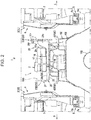
- FIG. 2 is an enlarged sectional view illustrating a II-II section of FIG. 1 .
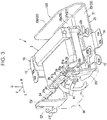
- FIG. 3 is a perspective view of the vehicular auxiliary machine and the arrangement structure, when viewed from a rear side and obliquely leftwardly from above.
- FIG. 4 is a perspective view of the vehicular auxiliary machine and the arrangement structure, when viewed from a front side and obliquely rightwardly from above.
- FIG. 5 is a plan view of the vehicular auxiliary machine and the arrangement structure.
- FIG. 6 is an exploded perspective view of the vehicular auxiliary machine and the arrangement structure of the vehicular auxiliary machine.
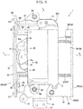
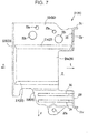
- FIG. 7 is a plan view of a protection bracket.
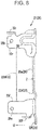
- FIG. 8 is a left side view of the protection bracket.
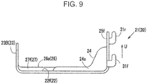
- FIG. 9 is a front view of the protection bracket, when viewed from a front side.
- FIG. 10 is a perspective view illustrating an essential part of a configuration, on a vehicle body side, of a periphery of the arrangement structure of the vehicular auxiliary machine of the present embodiment.
- FIG. 11 is an external view of a vehicle-body-side DCM bracket pedestal member for mounting and supporting the arrangement structure of the vehicular auxiliary machine.
- the arrow F indicates a vehicle front side
- the arrow W indicates a vehicular width direction
- the arrow R indicates a vehicle right side
- the arrow L indicates a vehicle left side
- the arrow U indicates a vehicle upper side.
- a lower surface of a passenger compartment is constituted by a floor panel 100 extending substantially horizontally in a front-rear direction between an unillustrated dashboard lower panel and an unillustrated rear kickup portion.
- a tunnel portion 101 projecting upwardly (inwardly of a passenger compartment) and extending in a vehicular front-rear direction is formed at a middle portion of the floor panel 100 in the vehicular width direction.
- a tunnel member 102, which defines a closed section between itself and the tunnel portion 101, is joined to an upper portion of the tunnel portion 101.
- the tunnel member 102 is a vehicle body rigid member extending in the vehicular front-rear direction along the upper portion of the tunnel portion 101.
- an exhaust pipe 103 as one of members of an exhaust system of an engine is disposed inside a lower space of the tunnel portion 101 on a vehicle outer side.
- a side sill 104 as a vehicle body rigid member extending in the vehicular front-rear direction is joined to both ends of the floor panel 100 in the vehicular width direction.
- front seats 3 are arranged side by side in the vehicular width direction on a front portion of the front panel 100.
- the front seats 3 comprise a driver's seat 3R disposed on a right side with respect to the tunnel portion 101, and a passenger's seat 3L disposed on a left side with respect to the tunnel portion 101 in a right-hand drive vehicle.
- the driver's seat 3R and the passenger's seat 3L are constituted by right and left separate seats, each of which includes a seat cushion 3a, a seatback 3b, and a headrest 3c.
- a seat support structure 4 for supporting the seat cushion 3a, the seatback 3b, and the headrest 3c is provided on a lower portion of the front seat 3.
- the seat support structure 4 includes a slide mechanism 5 extending in the vehicular front-rear direction between itself and the front panel 100, and configured to support the seat cushion 3a in a seat front-rear direction (vehicular front-rear direction).
- the slide mechanism 5 is provided by a pair (left and right) in the vehicular width direction of the front seat 3 (in FIG. 2 , only one slide mechanism 5 is illustrated).
- the slide mechanism 5 is mainly constituted by a pair of left and right seat rails 5a fixed to the front panel 100, and a slider 5b slidably engaged with the seat rails 5a.
- the seat support mechanism 4 includes a support bracket 6, on each of left and right sides thereof, which is interposed between the slider 5b of the slide mechanism 5 and the seat cushion 3a, and configured to support the seat cushion 3a.
- a bar-shaped (pipe-shaped) seat cushion frame 7 extending linearly in the vehicular width direction spans between the left and right support brackets 6. Both ends of the seat cushion frame 7 in the vehicular width direction are fixed to the respective associated support brackets 6 by welding or the like.
- the seat cushion frame 7 may have a function as a stabilizer for transmitting driving of a driving unit (not illustrated) provided on one of left and right sides to the other of the left and right sides in order to drive a link member and the like included in a lifter mechanism (not illustrated), as necessary, in addition to a function as a reinforcing member for enhancing rigidity of a lower portion of the front seat 3.
- a driving unit not illustrated
- a link member and the like included in a lifter mechanism not illustrated
- an instrument panel 105 extending in the vehicular width direction is disposed on the front portion within the passenger compartment of the vehicle.
- a center console 106 projecting from the instrument panel 105 rearwardly of a vehicle body is disposed in such a way as to cover the tunnel member 102 extending in a front-rear direction from a passenger compartment side (from above) between the left and right front seats 3 (the passenger's seat 3L and the driver's seat 3R).
- a steering wheel 107 is disposed on a front side of the driver's seat 3R.
- a shift knob 108 is provided on the center console 106.
- the shift knob 108 is mounted and supported by the tunnel member 102 via a shift knob mounting pedestal member 50 to be described later (see FIG. 10 ).
- a DCM unit 1 is disposed behind the shift knob 108.
- the DCM unit 1 is constituted by a data communication module (DCM) 2 as a vehicular auxiliary machine of the present embodiment, and a DCM bracket 500.
- the DCM unit 1 is directly or indirectly mounted and supported by the tunnel member 102 on a vehicle body side, specifically, via a DCM bracket pedestal member 40 in a state that the DCM unit 1 is covered by the center console 106 from a passenger compartment side (from above), between the passenger's seat 3L and the driver's seat 3R arranged side by side in the vehicular width direction.
- the DCM bracket pedestal member 40 is integrally formed by a steel plate, specifically, by a pedestal portion 41, and a plurality of tunnel member mounting flanges 42 (42f and 42r) extending outwardly from the pedestal portion 41 in a plan view from below.
- a mounting hole 42a passes through the rear-side tunnel member mounting flange 42r of the plurality of tunnel member mounting flanges 42, which extends from a rear portion of the pedestal portion 41 downwardly and rearwardly.
- the rear-side tunnel member mounting flange 42r is fixedly fastened in the mounting hole 42a by using a bolt B1 and a nut (not illustrated).
- a mounting hole 42a passes through the front-side tunnel member mounting flange 42f of the plurality of tunnel member mounting flanges 42, which extends from a front portion of the pedestal portion 41 downwardly and toward left and right sides.
- the front-side tunnel member mounting flange 42f is fixedly fastened to the shift knob mounting pedestal member 50 in the mounting hole 42a by using a bolt B2 and a nut (not illustrated).
- a bolt B2 and a nut not illustrated.
- the front-side tunnel member mounting flange 42f is fixedly fastened to the tunnel member 102 via the shift knob mounting pedestal member 50.
- the shift knob mounting pedestal member 50 is fixedly fastened to an upper surface of the tunnel member 102 by a bolt and a nut in such a way that a front portion of the shift knob mounting pedestal member 50 is located on a front side with respect to the DCM bracket pedestal member 40. Further, the front-side tunnel member mounting flange 42f is mounted on a rear-side pedestal surface 51r, which is formed on a rear portion of the shift knob mounting pedestal member 50, and a front-side pedestal surface 51f on which the shift knob 108 is mounted is formed on a front portion of the shift knob mounting pedestal member 50.
- the shift knob mounting pedestal member 50 mounts not only the shift knob 108 but also a front portion of the DCM bracket pedestal member 40.
- front and rear portions of the shift knob 108 are supported from front and rear sides by two bracket members.
- One of the brackets for supporting a rear portion of the shift knob 108 corresponds to the shift knob mounting pedestal member 50.
- illustration of a bracket for supporting a front portion of the shift knob 108 is omitted.
- the DCM 2 is a vehicle-mounted emergency alert device for transmitting information from a vehicle to a rescue organization. As illustrated in FIGS. 2 to 6 , an entirety of the DCM 2 is covered by a housing.
- the DCM 2 has a three-dimensional shape, namely, a substantially rectangular shape in a plan view, with a long length in the vehicular front-rear direction, as compared with the vehicular width direction.
- the DCM 2 is disposed at such a height as to face the seat cushion frames 7 whose left and right surfaces are included in lower portions of the front seats 3R and 3L on respectively associated sides, particularly, inner end portions of bars of the seat cushions 3a in the vehicular width direction, at an intermediate position of the front right seat 3R and the front left seat 3L arranged side by side in the vehicular width direction, in a state that the DCM 2 is mounted on a vehicle body, namely, is supported by the vehicle-body-side DCM bracket pedestal member 40 via the DCM bracket 500.
- a DCM-side connector 2a for connecting a harness-side connector 61a which is included in one end of a harness 61 extending from the vehicle body for power supply and a signal line, is provided on one of left and right surfaces of the DCM 2, specifically, on a surface (left surface) on a left side (side facing the passenger's seat 3L) in the present embodiment.
- a harness connecting portion 29 is formed on a connecting portion between the harness-side connector 61a and the DCM-side connector 2a.
- the harness connecting portion 29 is formed on one of left and right surfaces of the DCM 2 in such a way that a front-rear length of the DCM 2 whose size in a front-rear direction is longer than a size in a width direction is not further lengthened.
- the DCM bracket 500 is mainly constituted by two members, namely, a DCM fixing bracket 10 for fixing the DCM 2, and a protection bracket 20 mounted to the vehicle body.
- the protection bracket 20 includes a base surface 22 constituting a bottom surface, left and right vertical wall portions 23 (23A and 23B), which stand upright substantially at a right angle with respect to the base surface 22 from both outer ends of the base surface 22 in the vehicular width direction, and ribs 24 formed to span between the left vertical wall portion 23A and the base surface 22.
- the left and right vertical wall portions 23 are spaced away from each other via the base surface 22 in the vehicular width direction.
- the vertical wall portion 23A on a vehicle left side specifically, the vertical wall portion 23A (hereinafter, referred to as the "harness-side vertical wall portion 23A") on a side close to the harness connecting portion 29 stands upright substantially at a right angle with respect to the base surface 22 in such a way as to interpose between the passenger's seat 3L and the DCM 2 in the vehicular width direction.
- the harness-side vertical wall portion 23A is formed to have a height higher than the right vertical wall portion 23B.
- the right vertical wall portion 23B specifically, the vertical wall portion 23B (hereinafter, referred to as the "non-harness-side vertical wall portion 23B") on a side far from the harness connecting portion 29 in the vehicular width direction (a side opposite to the vertical wall portion 23A with respect to the DCM 2 in the vehicular width direction) stands upright substantially at a right angle with respect to the base surface 22 in such a way as to interpose between the driver's seat 3R and the DCM 2 in the vehicular width direction.
- the protection bracket 20 is mainly constituted by two members, namely, a protection bracket body 21 including the base surface 22 and the non-harness-side vertical wall portion 23B, and a plate-shaped protection plate 28 whose shape is similar to a shape of the harness-side vertical wall portion 23A in a plan view, when viewed from the passenger's seat 3L side.
- a front-side upright portion 25f and a rear-side upright portion 25r which stand upright substantially at a right angle with respect to the base surface 22 from front and rear ends of a left end portion of the base surface 22 are formed on the left end portion of the base surface 22 of the protection bracket body 21.
- harness-side vertical wall portion 23A is formed by the front-side upright portion 25f, the rear-side upright portion 25r, and the protection plate 28.
- a front-side engagement projecting piece 31f which projects, while bending from an intermediate portion of a front edge of the front-side upright portion 25f in an up-down direction forwardly, leftwardly, and upwardly in this order, is formed on the front-side upright portion 25f.
- a rear-side engagement projecting piece 31r which projects, while bending from an upper portion of a rear edge of the rear-side upright portion 25r rearwardly, leftwardly, and upwardly in this order, is formed on the rear-side upright portion 25r.
- a front-side engaged projecting piece 32f which projects, while bending from an intermediate portion of a front edge of the protection plate 28 in an up-down direction forwardly and downwardly in this order, is formed on the protection plate 28.
- a rear-side engaged projecting piece 32r which projects, while bending from an upper portion of a rear edge of the protection plate 28 rearwardly and downwardly in this order, is formed on the protection plate 28.
- the protection bracket 20 allows, on front and rear sides thereof, engagement between the front-side engagement projecting piece 31f of the front-side upright portion 25f and the front-side engaged projecting piece 32f of the protection plate 28, and engagement between the rear-side engagement projecting piece 31r of the rear-side upright portion 25r and the rear-side engaged projecting piece 32r of the protection plate 28.
- the protection bracket body 21 is configured such that body-side mounting holes 25a and 25b respectively pass through upper portions of the front-side upright portion 25f and the rear-side upright portion 25r in a plate thickness direction (vehicular width direction).
- the protection plate 28 is configured such that protection-plate-side mounting holes 28a and 28b pass through the protection plate 28 in a plate thickness direction in upper front and rear portions of the protection plate 28, specifically, in portions of the protection plate 28 facing the body-side mounting holes 25a and 25b, when the protection plate 28 is engaged with the protection bracket body 21.
- the DCM unit 1 of the present embodiment is mounted to the vehicle body after the DCM 2, the DCM fixing bracket 10, and the protection bracket 20 are integrally incorporated (assembled).
- the DCM unit 1 is mounted to the vehicle body in a state that the protection plate 28 is not mounted.
- the protection plate 28 is temporarily fixed to the protection bracket body 21, and thereafter, is mounted to the protection bracket body 21 by using the bolts B3 and the nuts N3.
- the harness-side vertical wall portion 23A it possible to form the harness-side vertical wall portion 23A on a left surface of the DCM unit 1. As illustrated in FIG. 2 , it is possible to dispose the harness-side vertical wall portion 23A between the passenger's seat 3L and the DCM 2 in the vehicular width direction.
- a bulging portion 33 whose portion from a middle portion in a front-rear direction toward a lower end portion bulges toward one side in a plate thickness direction (in this example, toward a left side) with respect to an outer periphery of the portion, is formed on a surface of the protection bracket 20.
- a bead 34 which defines a ridge of the bulging portion 33 is formed on a perimeter of the bulging portion 33 except for a lower end thereof.
- the bead 34 includes a front-rear-direction bead 34a extending along the vehicular front-rear direction.
- the front-rear-direction bead 34a is a reinforcing member for increasing strength of the protection bracket 20, when a part of the seat cushion 3a of the passenger's seat 3L is abutted against the protection bracket 20 when a side collision occurs.
- the ribs 24 are formed side by side away from each other by a certain clearance in the vehicular front-rear direction.
- the ribs 24 (the front rib 24 and the rear rib 24) are formed to span between the front-side upright portion 25f and the base surface 22 at a corner portion (inner corner portion) of the front-side upright portion 25f and the base surface 22.
- the ribs 24 have a same shape, and, each of the ribs 24 includes a surface 24s parallel to the vehicular width direction and an up-down direction, specifically, the surface 24s orthogonal to a front-rear direction.
- the rib 24 projects upwardly with respect to an upper surface of a front portion 22f of the base surface 22 (base surface front portion 22f) over the entire length of the front portion 22f in the vehicular width direction, and is formed to have a substantially inverted L-shape in a rear view, when viewed from a vehicle front side, while projecting rightwardly of the vehicle with respect to a right surface (inner surface in the vehicular width direction) of the front-side upright portion 25f at a position immediately before a position where a left portion of the vehicle reaches the body-side mounting hole 25a of the front-side upright portion 25f (see FIG. 2 ).
- a bead 35 extending in an up-down direction including a corner portion with respect to the base surface 22 is formed on the rear-side upright portion 25r (see FIGS. 4 and 6 ).
- a pedestal portion 26 bulging with respect to an upper surface of each of front and rear portions of the base surface 22 (the base-surface front portion 22f and a base-surface rear portion 22r) is formed at an intermediate portion of the base surface 22 of the protection bracket body 21 in a front-rear direction.
- a flat-shaped pedestal surface 26a capable of placing the DCM fixing bracket 10 is formed on an upper surface of the pedestal portion 26.
- a harness mounting space Z capable of mounting the harness 61 extending from the harness connecting portion 29 (harness-side connector 61a) downwardly is formed into a cutout shape in a left portion of the pedestal portion 41, and in an inner portion of the pedestal portion 41 with respect to the front-side upright portion 25f and the rear-side upright portion 25r in the vehicular width direction.
- a step portion 27 bulging stepwise with respect to a front portion of the base surface 22 is formed on each of a front edge and a rear edge of the pedestal portion 41.
- the step portions 27 (a front-side step portion 27f and a rear-side step portion 27r) each extends linearly in the vehicular width direction.
- the rear-side step portion 27r extends in the vehicular width direction in such a way as to connect the non-harness-side vertical wall portion 23B and the harness-side vertical wall portion 23A (rear-side upright portion 25r).
- a mounting hole 22a passes through two portions of a rear portion of the base-surface rear portion 22r away from each other in the vehicular width direction, and a portion of the base-surface front portion 22f at a position on a front side with respect to the ribs 24, namely, three portions in total, specifically, portions associated with mounting holes 41a formed in the pedestal portion 41 of the DCM bracket pedestal member 40 illustrated in FIGS. 10 and 11 .
- the protection bracket 20 is mounted to the vehicle-side DCM bracket pedestal member 40 by fixedly fastening via the mounting holes 41a and the mounting holes 22a by using bolts B4 (see FIG. 5 ) and nuts (unillustrated) in a state that the DCM fixing bracket 10 is placed on the pedestal portion 41 of the DCM bracket pedestal member 40.
- the DCM fixing bracket 10 is integrally formed by a DCM mounting pedestal portion 11A for mounting the DCM 2 on an outer periphery of the DCM fixing bracket body portion 11 having a substantially rectangular shape in a plan view; a setting portion 11B for setting the DCM fixing bracket 10 on the pedestal surface 26a of the protection bracket 20; a front-side grounding flange portion 12 for fixedly connecting an unillustrated grounding terminal, which is disposed on a front side of the DCM 2, a rear extension portion 13 extending rearwardly with respect to the DCM fixing bracket body portion 11; a rear-side grounding flange portion 14 for fixedly connecting an unillustrated grounding terminal, which is disposed on a rear side of the DCM 2; and a clip-mounting flange portion 15 for fixing a harness (not illustrated) to be connected to an unillustrated vehicular auxiliary machine other than the DCM 2.
- the DCM mounting pedestal portion 11A is formed into a flat shape.
- a mounting hole 11a for fixedly fastening the DCM 2 by using a bolt and a nut at four corner portions of the DCM mounting pedestal portion 11A is formed in the DCM mounting pedestal portion 11A.
- through-holes 22b formed in the base-surface rear portion 22r of the protection bracket 22 in association with the mounting holes 11a in a plan view are service holes for insertion of bolts (unillustrated), which are used in mounting the DCM 2 to the DCM mounting pedestal portion 11A.
- the setting portion 11B is formed into a downward recess with respect to the DCM mounting pedestal portion 11A at a middle portion of the DCM fixing bracket body portion 11.
- a lower surface (bottom surface) of the setting portion 11B is formed into a flat shape in such a way that the setting portion 11B is able to come into surface contact with the pedestal surface 26a of the protection bracket 20.
- the front-side grounding flange portion 12 stands upright at a right angle with respect to the DCM mounting pedestal portion 11A from a front end of the DCM fixing bracket body portion 11, and extends horizontally and rearwardly from an upper end of the DCM fixing bracket body portion 11.
- the rear extension portion 13 is disposed above the base-surface rear portion 22r of the protection bracket 20. Further, as illustrated in FIG. 5 , the rear extension portion 13 extends horizontally and rearwardly from a rear end of the DCM fixing bracket body portion 11 in such a way as to detour the mounting holes 22a (see FIG. 7 ) in a plan view.
- the rear-side grounding flange portion 14 and the clip-mounting flange portion 15 respectively extend horizontally rearwardly, and obliquely leftwardly and rearwardly from the rear extension portion 13.
- the DCM fixing bracket 10 is fixed only via the protection bracket 10 with respect to the vehicle body, specifically, the DCM bracket pedestal member 40 (see FIGS. 10 and 11 ) in such a way that a side collision load is not directly transmitted from the vehicle body when a side collision occurs.
- the DCM fixing bracket 10 is displaceable relative to the protection bracket 20, when the protection bracket 20 is deformed (see FIG. 2 ).
- a lower surface of the setting portion 11B of the DCM fixing bracket 10 comes into surface contact with the pedestal surface 26a of the protection bracket 20, and is welded to the pedestal surface 26a at the contact portion.
- the DCM fixing bracket 10 and the protection bracket 20 are fixed only by welding the lower surface of the setting portion 11B and the pedestal surface 26a.
- the DCM fixing bracket 10 is fixed neither to the DCM fixing bracket 10 except for the welded portion A, nor to the vehicle body.
- the DCM fixing bracket 10 is displaceable relative to the protection bracket 20, when the lower surface of the setting portion 11B is detached from the pedestal surface 26a of the protection bracket 20 when a side collision occurs.
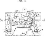
- FIG. 12 is an operation explanatory diagram illustrating a state of an initial stage of side collision, which is associated with FIG. 2 .
- FIG. 13 is an operation explanatory diagram illustrating a state of a middle stage of side collision, which is associated with FIG. 2 .
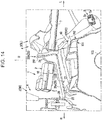
- FIG. 14 is an operation explanatory diagram illustrating a state of a last stage of side collision, which is associated with FIG. 2 .
- the seat support structure 4 of the passenger's seat 3L is displaced from a state illustrated in FIG. 2 inwardly in the vehicular width direction, specifically, toward the DCM unit 1 by disengagement of the seat rail 5a from the floor panel 100, deformation of the seat support structure 4 itself, or the like.
- the harness-side vertical wall portion 23A is received by the ribs 24 in such a way that the harness-side vertical wall portion 23A is not inclined toward the DCM 2, and the harness-side vertical wall portion 23A (protection plate 28) is reinforced by the front-rear-direction bead 34a in such a way that the harness-side vertical wall portion 23A itself is not deformed (see FIG. 6 ). Therefore, it is possible to securely receive a side collision load from the seat support structure 4 of the passenger's seat 3L.
- the DCM fixing bracket 10 is detached from the protection bracket 20 at a welded portion A (see FIG. 2 ) between the pedestal portion 26 of the protection bracket body 21 and the setting portion 11B of the DCM fixing bracket 10, whereby it is possible to displace the DCM fixing bracket 10 in such a way that the DCM fixing bracket 10 is lifted upwardly together with the DCM 2 (see the bold arrow in FIG. 14 ).
- the DCM unit 1 of the present embodiment is an arrangement structure of a vehicular auxiliary machine in which the DCM 2 as a vehicular auxiliary machine is disposed between the front seats 3R and 3L arranged side by side in a vehicular width direction of a vehicle body.
- the DCM unit 1 includes the DCM bracket 500 on which the DCM 2 is mounted, and which is fixed to the vehicle body.
- the DCM 2 includes the harness connecting portion 29 to which the harness 61 is connected, and is disposed in such a way that the harness connecting portion 29 is located on a side of the front seat 3L (passenger's seat 3L).
- the protection bracket 20 of the DCM bracket 500 includes: the base surface 22, the paired vertical wall portions 23 (23A and 23B) which stand upright with respect to the base surface 22 in such a way as to be away from each other in the vehicular width direction, between the DCM 2 and each of the front seats 3 (3R, 3L); and the ribs 24 spanning between the harness-side vertical wall portion 23A being one of the paired vertical wall portions 23A and 23B close to the harness connecting portion 29 of the DCM 2, and the base surface 22 (see FIGS. 2 to 7 , and 9 ).
- the above configuration is able to reduce a possibility that the DCM 2 directly interferes with the passenger's seat 3L when a side collision occurs.
- the harness-side vertical wall portion 23A is supported by the ribs 24 in such a way that the harness-side vertical wall portion 23A is not inclined toward the DCM 2, it is possible to more securely protect the harness connecting portion 29, as compared with a case where the harness-side vertical wall portion 23A is not supported by the ribs 24. Therefore, it is possible to function the DCM 2, even when a part of the passenger's seat 3L (e.g. the seat cushion frame 7) is abutted against the harness-side vertical wall portion 23A when a side collision occurs.
- a part of the passenger's seat 3L e.g. the seat cushion frame 7
- the rib 24 is formed by the surface 24s parallel to the vehicular width direction (see FIGS. 2 to 4 , 6 , and 9 ).
- the above configuration is able to more securely prevent that the harness-side vertical wall portion 23A is inclined by the rib 24 formed by the surface 24s parallel to the vehicular width direction, even when a part of the passenger's seat 3L is abutted against the harness-side vertical wall portion 23A when a side collision occurs.
- the harness-side vertical wall portion 23A is formed by the protection plate 28, which is a member independent of the DCM fixing bracket 10 and the protection bracket body 21, and is detachably attached to the protection bracket body 21 (see FIGS. 3 to 6 ).
- the above configuration is able to release the harness connecting portion 29 without being covered by the protection plate 28 from a left side by detaching the protection plate 28 from the protection bracket body 21. Therefore, it is possible to appropriately and easily connect the harness 61 to the DCM 2 without being obstructed by the protection plate 28, when the harness 61 is connected to the DCM 2. Further, by mounting the protection plate 28 on the protection bracket body 21 when the vehicle is traveling (ordinary state), it is possible to protect the harness connecting portion 29 against contact with the protection plate 28, even when a part of the passenger's seat 3L is displaced toward the DCM 2 when a side collision occurs.
- the front-rear-direction bead 34a as a reinforcing portion extending along the vehicular front-rear direction is formed on the harness-side vertical wall portion 23A (see FIGS. 4 and 6 ).
- the above configuration is able to increase strength of the harness-side vertical wall portion 23A against contact with a part of the passenger's seat 3L when a side collision occurs by forming the front-rear-direction bead 34a as a reinforcing portion on the harness-side vertical wall portion 23A, and is able to enhance protection performance of the harness connecting portion 29 by the harness-side vertical wall portion 23A.
- the pedestal portion 26 bulging with respect to the base surface 22 is formed on the base surface 22.
- the step portion 27 (27f and 27r) extending in the vehicular width direction is formed on an end of the pedestal portion 26 (see FIGS. 3 , and 5 to 9 ).
- the above configuration is able to increase compression strength of the base surface 22 in the vehicular width direction by the pedestal portion 26 including the step portion 27 each extending in the vehicular width direction on an end thereof. Therefore, it is possible to retain a shape of the base surface 22 in such a way as to prevent a clearance between the vertical wall portions 23 from being narrowed by crush of the base surface 22 in the vehicle width direction when a side collision occurs.
- reinforcing the harness-side vertical wall portion 23A by forming the ribs 24 also prevents relative weakening of the base surface 22, and it is also possible to reinforce the base surface 22 by the step portions 27. Therefore, it is possible to protect the DCM 2 by the vertical wall portion 23 and the base surface 22 when a side collision occurs.
- the present disclosure is not limited to a configuration according to the embodiment, and various variations may be applied.
- the harness connecting portion 29 may be provided on a right side (driver's seat 3R side).
- the harness-side vertical wall portion 23A and the non-harness-side vertical wall portion 23B may be disposed in such a way that left and right sides are reversed.
- an arrangement structure of a vehicular auxiliary machine of the present disclosure is not limited to a structure in which a vehicular auxiliary machine is disposed between front seats arranged side by side in a vehicular width direction.
- the present disclosure may be applied to a structure in which a vehicular auxiliary machine is disposed between rear seats arranged side by side in a vehicular width direction.
- An arrangement structure of a vehicular auxiliary machine includes: the vehicular auxiliary machine disposed between seats arranged side by side in a vehicular width direction of a vehicle body; a bracket on which the vehicular auxiliary machine is mounted, and which is fixed to the vehicle body; and a harness to be connected to the vehicular auxiliary machine.
- the vehicular auxiliary machine includes a harness connecting portion to which the harness is connected, and is disposed in such a way that the harness connecting portion is located on a side of one of the seats.
- the bracket includes a base surface, a pair of vertical wall portions which stand upright with respect to the base surface in such a way that the vertical wall portions are away from each other in the vehicular width direction between the vehicular auxiliary machine and each of the seats, and a rib spanning between a harness-side vertical wall portion and the base surface, the harness-side vertical wall portion being one of the paired vertical wall portions close to the harness connecting portion of the vehicular auxiliary machine.
- the vehicular auxiliary machine directly interferes with a seat when a side collision occurs.
- the harness connecting portion is more securely protected by the harness-side vertical wall portion and the rib on a side of the harness connecting portion, it is possible to function the vehicular auxiliary machine even when a seat is abutted against the harness-side vertical wall portion when a side collision occurs.
- the arrangement structure of the vehicular auxiliary machine according to another aspect of the present disclosure is such that, in the above aspect, the rib is constituted by a surface parallel to the vehicular width direction.
- the arrangement structure of the vehicular auxiliary machine according to another aspect of the present disclosure is such that, in the above aspect, the harness-side vertical wall portion includes a protection plate provided independently of the bracket, and detachably attached to the bracket.
- the arrangement structure of the vehicular auxiliary machine according to another aspect of the present disclosure is such that, in the above aspect, the harness-side vertical wall portion includes a reinforcing portion formed in such a way as to extend along a vehicular front-rear direction.
- the reinforcing portion may be formed by a step portion (ridge portion) extending along a vehicular front-rear direction, a concave or convex bead, a rib (thickened portion), or a member formed by combining at least one of these elements, for example.
- the arrangement structure of the vehicular auxiliary machine according to another aspect of the present disclosure is such that, in the above aspect, the base surface includes a pedestal portion formed in such a way as to bulge with respect to the base surface, and the pedestal portion includes a step portion formed on an end of the pedestal portion in such a way as to extend in the vehicular width direction.
- the step portion formed on an end of the pedestal portion in such a way as to extend in the vehicular width direction enables to increase strength of the base surface in the vehicular width direction, it is possible to retain a shape of the base surface in such a way as to prevent a clearance between the vertical wall portions from being narrowed by crush of the base surface in the vehicle width direction when a side collision occurs. Thus, it is possible to protect the vehicular auxiliary machine from damage.
- An arrangement structure of a vehicular auxiliary machine includes: the vehicular auxiliary machine disposed between seats arranged side by side in a vehicular width direction of a vehicle body; and a bracket on which the vehicular auxiliary machine is mounted, and which is fixed to the vehicle body.
- the bracket includes an auxiliary machine fixing bracket to which the vehicular auxiliary machine is fixed, and a protection bracket having a vertical wall portion between a seat and the vehicular auxiliary machine.
- the auxiliary machine fixing bracket is configured to be displaceable relative to the protection bracket, when the protection bracket is deformed by contact against the seat.
- the auxiliary machine fixing bracket is displaceable relative to the protection bracket. Therefore, it is possible to prevent damage of the vehicular auxiliary machine itself accompanied by deformation of the protection bracket.
- the arrangement structure of the vehicular auxiliary machine according to another aspect of the present disclosure is such that, in the above aspect, the auxiliary machine fixing bracket is fixed only via the protection bracket with respect to the vehicle body in such a way that a side collision load is not transmitted from the vehicle body.
- the auxiliary machine fixing bracket is fixed only via the protection bracket with respect to the vehicle body in such a way that a side collision load is not transmitted from the vehicle body. Therefore, there is no likelihood that a side collision load is transmitted from the vehicle body to the auxiliary machine fixing bracket directly due to displacement of the auxiliary machine fixing bracket relative to the protection bracket when a side collision occurs. Thus, it is possible to prevent damage of the vehicular auxiliary machine itself against a side collision load.
- the arrangement structure of the vehicular auxiliary machine according to another aspect of the present disclosure is such that, in the above aspect, the auxiliary machine fixing bracket is detachably fixed to the protection bracket by welding.
Landscapes
- Engineering & Computer Science (AREA)
- Mechanical Engineering (AREA)
- Body Structure For Vehicles (AREA)
- Seats For Vehicles (AREA)
Claims (8)
- Anordnungsstruktur einer Fahrzeughilfsmaschine (2) in einem Fahrzeug, umfassend:die Fahrzeughilfsmaschine (2), die zwischen Sitzen (3) angebracht werden kann, die in Fahrzeugbreitenrichtung einer Fahrzeugkarosserie (101) nebeneinander angeordnet sind; undeinen Träger (500), auf dem die Fahrzeughilfsmaschine (2) montiert ist, und der an der Fahrzeugkarosserie (101) fixiert werden kann; undeinen Kabelbaum zum Anschluss an die Fahrzeughilfsmaschine,wobei die Fahrzeughilfsmaschine (2) einen Kabelbaumverbindungsabschnitt (29) aufweist, an den der Kabelbaum (61) angeschlossen werden kann, und so angebracht ist, dass sich der Kabelbaumverbindungsabschnitt (29) in der Einbauposition der Anordnungsstruktur in der Fahrzeugkarosserie (101) auf einer Seite eines der Sitze (3) befindet, undder Träger (500) Folgendes umfasst:eine Grundfläche (22),zwei vertikale Wandabschnitte (23), die in Bezug auf die Grundfläche (22) in einer solchen Weise aufrecht stehen, dass die vertikalen Wandabschnitte (23) in Fahrzeugbreitenrichtung zwischen der Fahrzeughilfsmaschine (2) und jedem der Sitze (3) voneinander entfernt sind, undeine Rippe (24), die sich zwischen einem kabelbaumseitigen vertikalen Wandabschnitt (23A) und der Grundfläche (22) erstreckt, wobei der kabelbaumseitige vertikale Wandabschnitt (23A) derjenige der beiden vertikalen Wandabschnitte (23) ist, der näher an dem Kabelbaumverbindungsabschnitt (29) der Fahrzeughilfsmaschine (2) liegt als der andere vertikale Wandabschnitt (23B) der beiden vertikalen Wandabschnitte (23).
- Anordnungsstruktur der Fahrzeughilfsmaschine (2) in einem Fahrzeug nach Anspruch 1, wobei
die Rippe (24) durch eine zu der Fahrzeugbreitenrichtung parallele Fläche gebildet wird. - Anordnungsstruktur der Fahrzeughilfsmaschine (2) in einem Fahrzeug nach Anspruch 1 oder 2, wobei
der kabelbaumseitige vertikale Wandabschnitt (23A) eine Schutzplatte (28) aufweist, die unabhängig von dem Träger (500) vorgesehen und lösbar an dem Träger (500) befestigt ist. - Anordnungsstruktur der Fahrzeughilfsmaschine (2) in einem Fahrzeug nach einem der Ansprüche 1 bis 3, wobei
der kabelbaumseitige vertikale Wandabschnitt (23A) einen Verstärkungsabschnitt (34a) aufweist, der so ausgebildet ist, dass er sich entlang einer Vorwärts-Rückwärts-Richtung des Fahrzeugs erstreckt. - Anordnungsstruktur der Fahrzeughilfsmaschine (2) in einem Fahrzeug nach einem der Ansprüche 1 bis 4, wobei
die Grundfläche (22) einen Sockelabschnitt (26) aufweist, der so ausgebildet ist, dass er sich in Bezug auf die Grundfläche (22) wölbt, und
der Sockelabschnitt (26) einen Stufenabschnitt (27) aufweist, der an einem Ende des Sockelabschnitts (26) so ausgebildet ist, dass er sich in Fahrzeugbreitenrichtung erstreckt. - Anordnungsstruktur einer Fahrzeughilfsmaschine nach einem der vorhergehenden Ansprüche, wobei
der Träger (500) einen Hilfsmaschinenhaltewinkel (10) aufweist, an dem die Fahrzeughilfsmaschine (2) befestigt ist, sowie einen Schutzbügel (20) mit den beiden vertikalen Wandabschnitten (23). - Anordnungsstruktur der Fahrzeughilfsmaschine (2) in einem Fahrzeug nach Anspruch 6, wobei
der Hilfsmaschinenhaltewinkel (10) nur über den Schutzbügel (20) in Bezug auf die Fahrzeugkarosserie (101) so fixiert ist, dass eine Seitenkollisionslast nicht von einer Seite der Fahrzeugkarosserie (101) aus übertragen wird. - Anordnungsstruktur der Fahrzeughilfsmaschine (2) in einem Fahrzeug nach Anspruch 7, wobei
der Hilfsmaschinenhaltewinkel (10) durch Schweißen lösbar an dem Schutzbügel (20) fixiert ist.
Applications Claiming Priority (2)
| Application Number | Priority Date | Filing Date | Title |
|---|---|---|---|
| JP2017030639A JP6380574B2 (ja) | 2017-02-22 | 2017-02-22 | 車両用補機の配設構造 |
| PCT/JP2018/003889 WO2018155152A1 (ja) | 2017-02-22 | 2018-02-06 | 車両用補機の配設構造 |
Publications (3)
| Publication Number | Publication Date |
|---|---|
| EP3572289A1 EP3572289A1 (de) | 2019-11-27 |
| EP3572289A4 EP3572289A4 (de) | 2019-12-04 |
| EP3572289B1 true EP3572289B1 (de) | 2021-05-05 |
Family
ID=63254286
Family Applications (1)
| Application Number | Title | Priority Date | Filing Date |
|---|---|---|---|
| EP18757666.5A Active EP3572289B1 (de) | 2017-02-22 | 2018-02-06 | Anordnungsstruktur einer fahrzeughilfsmaschine |
Country Status (6)
| Country | Link |
|---|---|
| US (1) | US11491922B2 (de) |
| EP (1) | EP3572289B1 (de) |
| JP (1) | JP6380574B2 (de) |
| CN (1) | CN110325404B (de) |
| RU (1) | RU2720587C1 (de) |
| WO (1) | WO2018155152A1 (de) |
Cited By (1)
| Publication number | Priority date | Publication date | Assignee | Title |
|---|---|---|---|---|
| EP4578679A4 (de) * | 2022-08-26 | 2025-10-29 | Nissan Motor | Struktur in einem fahrzeug mit hochspannungsvorrichtung |
Families Citing this family (3)
| Publication number | Priority date | Publication date | Assignee | Title |
|---|---|---|---|---|
| FR3109355B3 (fr) * | 2020-04-15 | 2022-03-25 | Psa Automobiles Sa | Traverse supérieure de bloc avant pour véhicule automobile |
| JP7260053B2 (ja) * | 2021-04-05 | 2023-04-18 | 日産自動車株式会社 | 高電圧電子ユニット車載構造 |
| JP7632390B2 (ja) * | 2022-05-30 | 2025-02-19 | トヨタ自動車株式会社 | 車両 |
Family Cites Families (23)
| Publication number | Priority date | Publication date | Assignee | Title |
|---|---|---|---|---|
| JP3726277B2 (ja) * | 1997-01-30 | 2005-12-14 | マツダ株式会社 | 車両用エアバックシステム |
| US6663411B2 (en) | 1998-07-15 | 2003-12-16 | Tyco Electronics Logistics Ag | Clamshell connector for airbag gas generator |
| AU4993999A (en) | 1998-07-15 | 2000-02-07 | Thomas & Betts International, Inc. | Connector for airbag gas generator |
| JP4306396B2 (ja) * | 2003-10-06 | 2009-07-29 | 株式会社デンソー | エアバッグecu |
| JP2005238990A (ja) | 2004-02-26 | 2005-09-08 | Denso Corp | 加速度センサの取付構造 |
| JP4752432B2 (ja) * | 2005-10-03 | 2011-08-17 | 日産自動車株式会社 | ユニット取付構造 |
| JP4367504B2 (ja) | 2007-03-06 | 2009-11-18 | 株式会社デンソー | 車載緊急通報装置 |
| ATE554974T1 (de) | 2008-03-26 | 2012-05-15 | Toyota Motor Co Ltd | Struktur und system zur aufprallerkennung |
| JP4640431B2 (ja) | 2008-03-26 | 2011-03-02 | トヨタ自動車株式会社 | 衝突検知構造及び乗員保護システム |
| DE102008040157A1 (de) * | 2008-07-03 | 2010-01-07 | Robert Bosch Gmbh | Steuergerät für Personenschutzmittel für ein Fahrzeug bzw. Verfahren zum Zusammenbau eines solchen Steuergeräts |
| US9162559B2 (en) * | 2009-05-28 | 2015-10-20 | Toyota Jidosha Kabushiki Kaisha | Fuel cell system and vehicle |
| JP5077611B2 (ja) * | 2009-05-28 | 2012-11-21 | トヨタ自動車株式会社 | 燃料電池システムおよび車両 |
| JP4924665B2 (ja) * | 2009-06-11 | 2012-04-25 | 日産自動車株式会社 | 車体の後部構造 |
| US9033399B2 (en) * | 2010-03-01 | 2015-05-19 | Sabic Global Technologies B.V. | Energy absorber elements and vehicle systems |
| US9861018B2 (en) * | 2011-10-24 | 2018-01-02 | Honda Motor Co., Ltd. | Wiring protective cover structure for electric drive vehicle |
| JP2013119326A (ja) * | 2011-12-07 | 2013-06-17 | Honda Motor Co Ltd | 電装部品の保護構造 |
| GB2500599B (en) * | 2012-03-26 | 2017-08-16 | Ford Global Tech Llc | Vehicle seat assembly |
| WO2017002191A1 (ja) * | 2015-06-30 | 2017-01-05 | 本田技研工業株式会社 | Ecuブラケット及び車両 |
| JP6350585B2 (ja) * | 2016-04-22 | 2018-07-04 | マツダ株式会社 | 緊急通報装置の配設構造 |
| US10150440B2 (en) * | 2016-05-19 | 2018-12-11 | Ford Global Technologies, Llc | Restraints control module attachment assembly |
| JP6702061B2 (ja) * | 2016-07-28 | 2020-05-27 | 三菱自動車工業株式会社 | 車体構造 |
| CN106891906B (zh) * | 2017-03-22 | 2018-12-11 | 青岛欧特美交通装备有限公司 | 一种具有垂向缓冲功能的一片式侧护板装置 |
| US11027680B2 (en) * | 2018-12-13 | 2021-06-08 | Ford Global Technologies, Llc | Vehicle tracks |
-
2017
- 2017-02-22 JP JP2017030639A patent/JP6380574B2/ja active Active
-
2018
- 2018-02-06 WO PCT/JP2018/003889 patent/WO2018155152A1/ja not_active Ceased
- 2018-02-06 CN CN201880012945.1A patent/CN110325404B/zh active Active
- 2018-02-06 EP EP18757666.5A patent/EP3572289B1/de active Active
- 2018-02-06 US US16/486,978 patent/US11491922B2/en active Active
- 2018-02-06 RU RU2019128446A patent/RU2720587C1/ru active
Cited By (1)
| Publication number | Priority date | Publication date | Assignee | Title |
|---|---|---|---|---|
| EP4578679A4 (de) * | 2022-08-26 | 2025-10-29 | Nissan Motor | Struktur in einem fahrzeug mit hochspannungsvorrichtung |
Also Published As
| Publication number | Publication date |
|---|---|
| CN110325404B (zh) | 2021-12-21 |
| US20200231098A1 (en) | 2020-07-23 |
| JP2018134973A (ja) | 2018-08-30 |
| JP6380574B2 (ja) | 2018-08-29 |
| EP3572289A4 (de) | 2019-12-04 |
| RU2720587C1 (ru) | 2020-05-12 |
| US11491922B2 (en) | 2022-11-08 |
| WO2018155152A1 (ja) | 2018-08-30 |
| CN110325404A (zh) | 2019-10-11 |
| EP3572289A1 (de) | 2019-11-27 |
Similar Documents
| Publication | Publication Date | Title |
|---|---|---|
| EP1749731B1 (de) | Hinterer Strukturaufbau für ein Kraftfahrzeug und Montageverfahren | |
| EP3572289B1 (de) | Anordnungsstruktur einer fahrzeughilfsmaschine | |
| EP2990307B1 (de) | Heckteilstruktur eines fahrzeugs | |
| EP2048063B1 (de) | Vorderteilkonstruktion einer Fahrzeugkarosserie | |
| JP5817137B2 (ja) | 車両の前部構造 | |
| EP0760328B1 (de) | Arretiervorrichtung für einen Fahrzeugaufbau | |
| CN101353036B (zh) | 汽车的仪表板组件 | |
| KR20100045800A (ko) | 서스펜션용 서브 프레임 | |
| EP3744619B1 (de) | Antriebsstrangtragstruktur für ein fahrzeug | |
| JPH05139237A (ja) | 助手席用エアバツグモジユールの取付け構造 | |
| JP3930004B2 (ja) | センサ配設構造 | |
| US12122454B2 (en) | Vehicle front portion structure | |
| US9022459B2 (en) | Assembly for fastening of a steering column for a motor vehicle | |
| JP2021075089A (ja) | 車両下部構造 | |
| JP6551435B2 (ja) | 車両用補機の配設構造 | |
| EP3546299A1 (de) | Knie-airbag-vorrichtung-befestigungsstruktur für ein fahrzeug, schutzsystem, fahrzeug und verfahren zur anordnung einer knie-airbag-vorrichtung | |
| JP2008302911A (ja) | 車体構造 | |
| JP4427076B2 (ja) | 前部車体構造 | |
| JP2019093855A (ja) | 衝突検出装置 | |
| JP2015074251A (ja) | 車体構造 | |
| JPS63176715A (ja) | 自動車の空調ユニツトの構造 | |
| CN109070941B (zh) | 机动车辆的前挡泥板结构 | |
| JP3726464B2 (ja) | キャブオーバ車両の衝突安全車体構造 | |
| JPH09221067A (ja) | 車両のカウル構造 | |
| JP2018161934A (ja) | 車体のフロア構造 |
Legal Events
| Date | Code | Title | Description |
|---|---|---|---|
| STAA | Information on the status of an ep patent application or granted ep patent |
Free format text: STATUS: THE INTERNATIONAL PUBLICATION HAS BEEN MADE |
|
| PUAI | Public reference made under article 153(3) epc to a published international application that has entered the european phase |
Free format text: ORIGINAL CODE: 0009012 |
|
| STAA | Information on the status of an ep patent application or granted ep patent |
Free format text: STATUS: REQUEST FOR EXAMINATION WAS MADE |
|
| 17P | Request for examination filed |
Effective date: 20190822 |
|
| AK | Designated contracting states |
Kind code of ref document: A1 Designated state(s): AL AT BE BG CH CY CZ DE DK EE ES FI FR GB GR HR HU IE IS IT LI LT LU LV MC MK MT NL NO PL PT RO RS SE SI SK SM TR |
|
| AX | Request for extension of the european patent |
Extension state: BA ME |
|
| A4 | Supplementary search report drawn up and despatched |
Effective date: 20191106 |
|
| RIC1 | Information provided on ipc code assigned before grant |
Ipc: B60R 16/02 20060101ALI20191030BHEP Ipc: B60R 21/00 20060101AFI20191030BHEP |
|
| DAV | Request for validation of the european patent (deleted) | ||
| DAX | Request for extension of the european patent (deleted) | ||
| STAA | Information on the status of an ep patent application or granted ep patent |
Free format text: STATUS: EXAMINATION IS IN PROGRESS |
|
| 17Q | First examination report despatched |
Effective date: 20200814 |
|
| GRAP | Despatch of communication of intention to grant a patent |
Free format text: ORIGINAL CODE: EPIDOSNIGR1 |
|
| STAA | Information on the status of an ep patent application or granted ep patent |
Free format text: STATUS: GRANT OF PATENT IS INTENDED |
|
| INTG | Intention to grant announced |
Effective date: 20201202 |
|
| GRAS | Grant fee paid |
Free format text: ORIGINAL CODE: EPIDOSNIGR3 |
|
| GRAA | (expected) grant |
Free format text: ORIGINAL CODE: 0009210 |
|
| STAA | Information on the status of an ep patent application or granted ep patent |
Free format text: STATUS: THE PATENT HAS BEEN GRANTED |
|
| AK | Designated contracting states |
Kind code of ref document: B1 Designated state(s): AL AT BE BG CH CY CZ DE DK EE ES FI FR GB GR HR HU IE IS IT LI LT LU LV MC MK MT NL NO PL PT RO RS SE SI SK SM TR |
|
| REG | Reference to a national code |
Ref country code: GB Ref legal event code: FG4D |
|
| REG | Reference to a national code |
Ref country code: CH Ref legal event code: EP |
|
| REG | Reference to a national code |
Ref country code: AT Ref legal event code: REF Ref document number: 1389432 Country of ref document: AT Kind code of ref document: T Effective date: 20210515 |
|
| REG | Reference to a national code |
Ref country code: DE Ref legal event code: R096 Ref document number: 602018016808 Country of ref document: DE |
|
| REG | Reference to a national code |
Ref country code: IE Ref legal event code: FG4D |
|
| REG | Reference to a national code |
Ref country code: LT Ref legal event code: MG9D |
|
| REG | Reference to a national code |
Ref country code: AT Ref legal event code: MK05 Ref document number: 1389432 Country of ref document: AT Kind code of ref document: T Effective date: 20210505 |
|
| PG25 | Lapsed in a contracting state [announced via postgrant information from national office to epo] |
Ref country code: BG Free format text: LAPSE BECAUSE OF FAILURE TO SUBMIT A TRANSLATION OF THE DESCRIPTION OR TO PAY THE FEE WITHIN THE PRESCRIBED TIME-LIMIT Effective date: 20210805 Ref country code: AT Free format text: LAPSE BECAUSE OF FAILURE TO SUBMIT A TRANSLATION OF THE DESCRIPTION OR TO PAY THE FEE WITHIN THE PRESCRIBED TIME-LIMIT Effective date: 20210505 Ref country code: FI Free format text: LAPSE BECAUSE OF FAILURE TO SUBMIT A TRANSLATION OF THE DESCRIPTION OR TO PAY THE FEE WITHIN THE PRESCRIBED TIME-LIMIT Effective date: 20210505 Ref country code: HR Free format text: LAPSE BECAUSE OF FAILURE TO SUBMIT A TRANSLATION OF THE DESCRIPTION OR TO PAY THE FEE WITHIN THE PRESCRIBED TIME-LIMIT Effective date: 20210505 Ref country code: LT Free format text: LAPSE BECAUSE OF FAILURE TO SUBMIT A TRANSLATION OF THE DESCRIPTION OR TO PAY THE FEE WITHIN THE PRESCRIBED TIME-LIMIT Effective date: 20210505 |
|
| PG25 | Lapsed in a contracting state [announced via postgrant information from national office to epo] |
Ref country code: GR Free format text: LAPSE BECAUSE OF FAILURE TO SUBMIT A TRANSLATION OF THE DESCRIPTION OR TO PAY THE FEE WITHIN THE PRESCRIBED TIME-LIMIT Effective date: 20210806 Ref country code: IS Free format text: LAPSE BECAUSE OF FAILURE TO SUBMIT A TRANSLATION OF THE DESCRIPTION OR TO PAY THE FEE WITHIN THE PRESCRIBED TIME-LIMIT Effective date: 20210905 Ref country code: NO Free format text: LAPSE BECAUSE OF FAILURE TO SUBMIT A TRANSLATION OF THE DESCRIPTION OR TO PAY THE FEE WITHIN THE PRESCRIBED TIME-LIMIT Effective date: 20210805 Ref country code: PL Free format text: LAPSE BECAUSE OF FAILURE TO SUBMIT A TRANSLATION OF THE DESCRIPTION OR TO PAY THE FEE WITHIN THE PRESCRIBED TIME-LIMIT Effective date: 20210505 Ref country code: LV Free format text: LAPSE BECAUSE OF FAILURE TO SUBMIT A TRANSLATION OF THE DESCRIPTION OR TO PAY THE FEE WITHIN THE PRESCRIBED TIME-LIMIT Effective date: 20210505 Ref country code: SE Free format text: LAPSE BECAUSE OF FAILURE TO SUBMIT A TRANSLATION OF THE DESCRIPTION OR TO PAY THE FEE WITHIN THE PRESCRIBED TIME-LIMIT Effective date: 20210505 Ref country code: PT Free format text: LAPSE BECAUSE OF FAILURE TO SUBMIT A TRANSLATION OF THE DESCRIPTION OR TO PAY THE FEE WITHIN THE PRESCRIBED TIME-LIMIT Effective date: 20210906 Ref country code: RS Free format text: LAPSE BECAUSE OF FAILURE TO SUBMIT A TRANSLATION OF THE DESCRIPTION OR TO PAY THE FEE WITHIN THE PRESCRIBED TIME-LIMIT Effective date: 20210505 |
|
| REG | Reference to a national code |
Ref country code: NL Ref legal event code: MP Effective date: 20210505 |
|
| PG25 | Lapsed in a contracting state [announced via postgrant information from national office to epo] |
Ref country code: NL Free format text: LAPSE BECAUSE OF FAILURE TO SUBMIT A TRANSLATION OF THE DESCRIPTION OR TO PAY THE FEE WITHIN THE PRESCRIBED TIME-LIMIT Effective date: 20210505 |
|
| PG25 | Lapsed in a contracting state [announced via postgrant information from national office to epo] |
Ref country code: EE Free format text: LAPSE BECAUSE OF FAILURE TO SUBMIT A TRANSLATION OF THE DESCRIPTION OR TO PAY THE FEE WITHIN THE PRESCRIBED TIME-LIMIT Effective date: 20210505 Ref country code: ES Free format text: LAPSE BECAUSE OF FAILURE TO SUBMIT A TRANSLATION OF THE DESCRIPTION OR TO PAY THE FEE WITHIN THE PRESCRIBED TIME-LIMIT Effective date: 20210505 Ref country code: SK Free format text: LAPSE BECAUSE OF FAILURE TO SUBMIT A TRANSLATION OF THE DESCRIPTION OR TO PAY THE FEE WITHIN THE PRESCRIBED TIME-LIMIT Effective date: 20210505 Ref country code: RO Free format text: LAPSE BECAUSE OF FAILURE TO SUBMIT A TRANSLATION OF THE DESCRIPTION OR TO PAY THE FEE WITHIN THE PRESCRIBED TIME-LIMIT Effective date: 20210505 Ref country code: SM Free format text: LAPSE BECAUSE OF FAILURE TO SUBMIT A TRANSLATION OF THE DESCRIPTION OR TO PAY THE FEE WITHIN THE PRESCRIBED TIME-LIMIT Effective date: 20210505 Ref country code: DK Free format text: LAPSE BECAUSE OF FAILURE TO SUBMIT A TRANSLATION OF THE DESCRIPTION OR TO PAY THE FEE WITHIN THE PRESCRIBED TIME-LIMIT Effective date: 20210505 Ref country code: CZ Free format text: LAPSE BECAUSE OF FAILURE TO SUBMIT A TRANSLATION OF THE DESCRIPTION OR TO PAY THE FEE WITHIN THE PRESCRIBED TIME-LIMIT Effective date: 20210505 |
|
| REG | Reference to a national code |
Ref country code: DE Ref legal event code: R097 Ref document number: 602018016808 Country of ref document: DE |
|
| PLBE | No opposition filed within time limit |
Free format text: ORIGINAL CODE: 0009261 |
|
| STAA | Information on the status of an ep patent application or granted ep patent |
Free format text: STATUS: NO OPPOSITION FILED WITHIN TIME LIMIT |
|
| 26N | No opposition filed |
Effective date: 20220208 |
|
| PG25 | Lapsed in a contracting state [announced via postgrant information from national office to epo] |
Ref country code: IS Free format text: LAPSE BECAUSE OF FAILURE TO SUBMIT A TRANSLATION OF THE DESCRIPTION OR TO PAY THE FEE WITHIN THE PRESCRIBED TIME-LIMIT Effective date: 20210905 Ref country code: AL Free format text: LAPSE BECAUSE OF FAILURE TO SUBMIT A TRANSLATION OF THE DESCRIPTION OR TO PAY THE FEE WITHIN THE PRESCRIBED TIME-LIMIT Effective date: 20210505 |
|
| PG25 | Lapsed in a contracting state [announced via postgrant information from national office to epo] |
Ref country code: IT Free format text: LAPSE BECAUSE OF FAILURE TO SUBMIT A TRANSLATION OF THE DESCRIPTION OR TO PAY THE FEE WITHIN THE PRESCRIBED TIME-LIMIT Effective date: 20210505 |
|
| REG | Reference to a national code |
Ref country code: DE Ref legal event code: R119 Ref document number: 602018016808 Country of ref document: DE |
|
| PG25 | Lapsed in a contracting state [announced via postgrant information from national office to epo] |
Ref country code: MC Free format text: LAPSE BECAUSE OF FAILURE TO SUBMIT A TRANSLATION OF THE DESCRIPTION OR TO PAY THE FEE WITHIN THE PRESCRIBED TIME-LIMIT Effective date: 20210505 |
|
| REG | Reference to a national code |
Ref country code: CH Ref legal event code: PL |
|
| REG | Reference to a national code |
Ref country code: BE Ref legal event code: MM Effective date: 20220228 |
|
| GBPC | Gb: european patent ceased through non-payment of renewal fee |
Effective date: 20220206 |
|
| PG25 | Lapsed in a contracting state [announced via postgrant information from national office to epo] |
Ref country code: LU Free format text: LAPSE BECAUSE OF NON-PAYMENT OF DUE FEES Effective date: 20220206 |
|
| PG25 | Lapsed in a contracting state [announced via postgrant information from national office to epo] |
Ref country code: FR Free format text: LAPSE BECAUSE OF NON-PAYMENT OF DUE FEES Effective date: 20220228 |
|
| PG25 | Lapsed in a contracting state [announced via postgrant information from national office to epo] |
Ref country code: LI Free format text: LAPSE BECAUSE OF NON-PAYMENT OF DUE FEES Effective date: 20220228 Ref country code: IE Free format text: LAPSE BECAUSE OF NON-PAYMENT OF DUE FEES Effective date: 20220206 Ref country code: GB Free format text: LAPSE BECAUSE OF NON-PAYMENT OF DUE FEES Effective date: 20220206 Ref country code: DE Free format text: LAPSE BECAUSE OF NON-PAYMENT OF DUE FEES Effective date: 20220901 Ref country code: CH Free format text: LAPSE BECAUSE OF NON-PAYMENT OF DUE FEES Effective date: 20220228 |
|
| PG25 | Lapsed in a contracting state [announced via postgrant information from national office to epo] |
Ref country code: BE Free format text: LAPSE BECAUSE OF NON-PAYMENT OF DUE FEES Effective date: 20220228 |
|
| PG25 | Lapsed in a contracting state [announced via postgrant information from national office to epo] |
Ref country code: MK Free format text: LAPSE BECAUSE OF FAILURE TO SUBMIT A TRANSLATION OF THE DESCRIPTION OR TO PAY THE FEE WITHIN THE PRESCRIBED TIME-LIMIT Effective date: 20210505 Ref country code: CY Free format text: LAPSE BECAUSE OF FAILURE TO SUBMIT A TRANSLATION OF THE DESCRIPTION OR TO PAY THE FEE WITHIN THE PRESCRIBED TIME-LIMIT Effective date: 20210505 |
|
| PG25 | Lapsed in a contracting state [announced via postgrant information from national office to epo] |
Ref country code: HU Free format text: LAPSE BECAUSE OF FAILURE TO SUBMIT A TRANSLATION OF THE DESCRIPTION OR TO PAY THE FEE WITHIN THE PRESCRIBED TIME-LIMIT; INVALID AB INITIO Effective date: 20180206 |
|
| PG25 | Lapsed in a contracting state [announced via postgrant information from national office to epo] |
Ref country code: TR Free format text: LAPSE BECAUSE OF FAILURE TO SUBMIT A TRANSLATION OF THE DESCRIPTION OR TO PAY THE FEE WITHIN THE PRESCRIBED TIME-LIMIT Effective date: 20210505 |
|
| PG25 | Lapsed in a contracting state [announced via postgrant information from national office to epo] |
Ref country code: MT Free format text: LAPSE BECAUSE OF FAILURE TO SUBMIT A TRANSLATION OF THE DESCRIPTION OR TO PAY THE FEE WITHIN THE PRESCRIBED TIME-LIMIT Effective date: 20210505 |