EP3559314B1 - Catalyst-coated membrane having a laminate structure - Google Patents
Catalyst-coated membrane having a laminate structure Download PDFInfo
- Publication number
- EP3559314B1 EP3559314B1 EP17818237.4A EP17818237A EP3559314B1 EP 3559314 B1 EP3559314 B1 EP 3559314B1 EP 17818237 A EP17818237 A EP 17818237A EP 3559314 B1 EP3559314 B1 EP 3559314B1
- Authority
- EP
- European Patent Office
- Prior art keywords
- membrane
- catalyst
- membrane component
- face
- layer
- Prior art date
- Legal status (The legal status is an assumption and is not a legal conclusion. Google has not performed a legal analysis and makes no representation as to the accuracy of the status listed.)
- Active
Links
Images



Classifications
-
- H—ELECTRICITY
- H01—ELECTRIC ELEMENTS
- H01M—PROCESSES OR MEANS, e.g. BATTERIES, FOR THE DIRECT CONVERSION OF CHEMICAL ENERGY INTO ELECTRICAL ENERGY
- H01M4/00—Electrodes
- H01M4/86—Inert electrodes with catalytic activity, e.g. for fuel cells
- H01M4/88—Processes of manufacture
- H01M4/8803—Supports for the deposition of the catalytic active composition
- H01M4/881—Electrolytic membranes
-
- C—CHEMISTRY; METALLURGY
- C25—ELECTROLYTIC OR ELECTROPHORETIC PROCESSES; APPARATUS THEREFOR
- C25B—ELECTROLYTIC OR ELECTROPHORETIC PROCESSES FOR THE PRODUCTION OF COMPOUNDS OR NON-METALS; APPARATUS THEREFOR
- C25B11/00—Electrodes; Manufacture thereof not otherwise provided for
- C25B11/04—Electrodes; Manufacture thereof not otherwise provided for characterised by the material
- C25B11/051—Electrodes formed of electrocatalysts on a substrate or carrier
- C25B11/073—Electrodes formed of electrocatalysts on a substrate or carrier characterised by the electrocatalyst material
- C25B11/075—Electrodes formed of electrocatalysts on a substrate or carrier characterised by the electrocatalyst material consisting of a single catalytic element or catalytic compound
- C25B11/081—Electrodes formed of electrocatalysts on a substrate or carrier characterised by the electrocatalyst material consisting of a single catalytic element or catalytic compound the element being a noble metal
-
- C—CHEMISTRY; METALLURGY
- C25—ELECTROLYTIC OR ELECTROPHORETIC PROCESSES; APPARATUS THEREFOR
- C25B—ELECTROLYTIC OR ELECTROPHORETIC PROCESSES FOR THE PRODUCTION OF COMPOUNDS OR NON-METALS; APPARATUS THEREFOR
- C25B1/00—Electrolytic production of inorganic compounds or non-metals
- C25B1/01—Products
- C25B1/02—Hydrogen or oxygen
- C25B1/04—Hydrogen or oxygen by electrolysis of water
-
- C—CHEMISTRY; METALLURGY
- C25—ELECTROLYTIC OR ELECTROPHORETIC PROCESSES; APPARATUS THEREFOR
- C25B—ELECTROLYTIC OR ELECTROPHORETIC PROCESSES FOR THE PRODUCTION OF COMPOUNDS OR NON-METALS; APPARATUS THEREFOR
- C25B11/00—Electrodes; Manufacture thereof not otherwise provided for
- C25B11/04—Electrodes; Manufacture thereof not otherwise provided for characterised by the material
- C25B11/051—Electrodes formed of electrocatalysts on a substrate or carrier
- C25B11/073—Electrodes formed of electrocatalysts on a substrate or carrier characterised by the electrocatalyst material
-
- C—CHEMISTRY; METALLURGY
- C25—ELECTROLYTIC OR ELECTROPHORETIC PROCESSES; APPARATUS THEREFOR
- C25B—ELECTROLYTIC OR ELECTROPHORETIC PROCESSES FOR THE PRODUCTION OF COMPOUNDS OR NON-METALS; APPARATUS THEREFOR
- C25B11/00—Electrodes; Manufacture thereof not otherwise provided for
- C25B11/04—Electrodes; Manufacture thereof not otherwise provided for characterised by the material
- C25B11/051—Electrodes formed of electrocatalysts on a substrate or carrier
- C25B11/073—Electrodes formed of electrocatalysts on a substrate or carrier characterised by the electrocatalyst material
- C25B11/091—Electrodes formed of electrocatalysts on a substrate or carrier characterised by the electrocatalyst material consisting of at least one catalytic element and at least one catalytic compound; consisting of two or more catalytic elements or catalytic compounds
- C25B11/097—Electrodes formed of electrocatalysts on a substrate or carrier characterised by the electrocatalyst material consisting of at least one catalytic element and at least one catalytic compound; consisting of two or more catalytic elements or catalytic compounds comprising two or more noble metals or noble metal alloys
-
- C—CHEMISTRY; METALLURGY
- C25—ELECTROLYTIC OR ELECTROPHORETIC PROCESSES; APPARATUS THEREFOR
- C25B—ELECTROLYTIC OR ELECTROPHORETIC PROCESSES FOR THE PRODUCTION OF COMPOUNDS OR NON-METALS; APPARATUS THEREFOR
- C25B13/00—Diaphragms; Spacing elements
- C25B13/02—Diaphragms; Spacing elements characterised by shape or form
-
- C—CHEMISTRY; METALLURGY
- C25—ELECTROLYTIC OR ELECTROPHORETIC PROCESSES; APPARATUS THEREFOR
- C25B—ELECTROLYTIC OR ELECTROPHORETIC PROCESSES FOR THE PRODUCTION OF COMPOUNDS OR NON-METALS; APPARATUS THEREFOR
- C25B13/00—Diaphragms; Spacing elements
- C25B13/04—Diaphragms; Spacing elements characterised by the material
- C25B13/08—Diaphragms; Spacing elements characterised by the material based on organic materials
-
- C—CHEMISTRY; METALLURGY
- C25—ELECTROLYTIC OR ELECTROPHORETIC PROCESSES; APPARATUS THEREFOR
- C25B—ELECTROLYTIC OR ELECTROPHORETIC PROCESSES FOR THE PRODUCTION OF COMPOUNDS OR NON-METALS; APPARATUS THEREFOR
- C25B9/00—Cells or assemblies of cells; Constructional parts of cells; Assemblies of constructional parts, e.g. electrode-diaphragm assemblies; Process-related cell features
- C25B9/17—Cells comprising dimensionally-stable non-movable electrodes; Assemblies of constructional parts thereof
- C25B9/19—Cells comprising dimensionally-stable non-movable electrodes; Assemblies of constructional parts thereof with diaphragms
-
- C—CHEMISTRY; METALLURGY
- C25—ELECTROLYTIC OR ELECTROPHORETIC PROCESSES; APPARATUS THEREFOR
- C25B—ELECTROLYTIC OR ELECTROPHORETIC PROCESSES FOR THE PRODUCTION OF COMPOUNDS OR NON-METALS; APPARATUS THEREFOR
- C25B9/00—Cells or assemblies of cells; Constructional parts of cells; Assemblies of constructional parts, e.g. electrode-diaphragm assemblies; Process-related cell features
- C25B9/17—Cells comprising dimensionally-stable non-movable electrodes; Assemblies of constructional parts thereof
- C25B9/19—Cells comprising dimensionally-stable non-movable electrodes; Assemblies of constructional parts thereof with diaphragms
- C25B9/23—Cells comprising dimensionally-stable non-movable electrodes; Assemblies of constructional parts thereof with diaphragms comprising ion-exchange membranes in or on which electrode material is embedded
-
- C—CHEMISTRY; METALLURGY
- C25—ELECTROLYTIC OR ELECTROPHORETIC PROCESSES; APPARATUS THEREFOR
- C25B—ELECTROLYTIC OR ELECTROPHORETIC PROCESSES FOR THE PRODUCTION OF COMPOUNDS OR NON-METALS; APPARATUS THEREFOR
- C25B9/00—Cells or assemblies of cells; Constructional parts of cells; Assemblies of constructional parts, e.g. electrode-diaphragm assemblies; Process-related cell features
- C25B9/60—Constructional parts of cells
- C25B9/65—Means for supplying current; Electrode connections; Electric inter-cell connections
-
- C—CHEMISTRY; METALLURGY
- C25—ELECTROLYTIC OR ELECTROPHORETIC PROCESSES; APPARATUS THEREFOR
- C25B—ELECTROLYTIC OR ELECTROPHORETIC PROCESSES FOR THE PRODUCTION OF COMPOUNDS OR NON-METALS; APPARATUS THEREFOR
- C25B9/00—Cells or assemblies of cells; Constructional parts of cells; Assemblies of constructional parts, e.g. electrode-diaphragm assemblies; Process-related cell features
- C25B9/70—Assemblies comprising two or more cells
- C25B9/73—Assemblies comprising two or more cells of the filter-press type
-
- H—ELECTRICITY
- H01—ELECTRIC ELEMENTS
- H01M—PROCESSES OR MEANS, e.g. BATTERIES, FOR THE DIRECT CONVERSION OF CHEMICAL ENERGY INTO ELECTRICAL ENERGY
- H01M4/00—Electrodes
- H01M4/86—Inert electrodes with catalytic activity, e.g. for fuel cells
- H01M4/88—Processes of manufacture
-
- H—ELECTRICITY
- H01—ELECTRIC ELEMENTS
- H01M—PROCESSES OR MEANS, e.g. BATTERIES, FOR THE DIRECT CONVERSION OF CHEMICAL ENERGY INTO ELECTRICAL ENERGY
- H01M8/00—Fuel cells; Manufacture thereof
- H01M8/04—Auxiliary arrangements, e.g. for control of pressure or for circulation of fluids
- H01M8/04082—Arrangements for control of reactant parameters, e.g. pressure or concentration
-
- H—ELECTRICITY
- H01—ELECTRIC ELEMENTS
- H01M—PROCESSES OR MEANS, e.g. BATTERIES, FOR THE DIRECT CONVERSION OF CHEMICAL ENERGY INTO ELECTRICAL ENERGY
- H01M8/00—Fuel cells; Manufacture thereof
- H01M8/04—Auxiliary arrangements, e.g. for control of pressure or for circulation of fluids
- H01M8/04082—Arrangements for control of reactant parameters, e.g. pressure or concentration
- H01M8/04197—Preventing means for fuel crossover
-
- H—ELECTRICITY
- H01—ELECTRIC ELEMENTS
- H01M—PROCESSES OR MEANS, e.g. BATTERIES, FOR THE DIRECT CONVERSION OF CHEMICAL ENERGY INTO ELECTRICAL ENERGY
- H01M8/00—Fuel cells; Manufacture thereof
- H01M8/10—Fuel cells with solid electrolytes
- H01M8/1004—Fuel cells with solid electrolytes characterised by membrane-electrode assemblies [MEA]
-
- H—ELECTRICITY
- H01—ELECTRIC ELEMENTS
- H01M—PROCESSES OR MEANS, e.g. BATTERIES, FOR THE DIRECT CONVERSION OF CHEMICAL ENERGY INTO ELECTRICAL ENERGY
- H01M8/00—Fuel cells; Manufacture thereof
- H01M8/10—Fuel cells with solid electrolytes
- H01M8/1016—Fuel cells with solid electrolytes characterised by the electrolyte material
- H01M8/1018—Polymeric electrolyte materials
-
- H—ELECTRICITY
- H01—ELECTRIC ELEMENTS
- H01M—PROCESSES OR MEANS, e.g. BATTERIES, FOR THE DIRECT CONVERSION OF CHEMICAL ENERGY INTO ELECTRICAL ENERGY
- H01M8/00—Fuel cells; Manufacture thereof
- H01M8/10—Fuel cells with solid electrolytes
- H01M2008/1095—Fuel cells with polymeric electrolytes
-
- H—ELECTRICITY
- H01—ELECTRIC ELEMENTS
- H01M—PROCESSES OR MEANS, e.g. BATTERIES, FOR THE DIRECT CONVERSION OF CHEMICAL ENERGY INTO ELECTRICAL ENERGY
- H01M2300/00—Electrolytes
- H01M2300/0017—Non-aqueous electrolytes
- H01M2300/0065—Solid electrolytes
- H01M2300/0082—Organic polymers
-
- H—ELECTRICITY
- H01—ELECTRIC ELEMENTS
- H01M—PROCESSES OR MEANS, e.g. BATTERIES, FOR THE DIRECT CONVERSION OF CHEMICAL ENERGY INTO ELECTRICAL ENERGY
- H01M2300/00—Electrolytes
- H01M2300/0088—Composites
- H01M2300/0094—Composites in the form of layered products, e.g. coatings
-
- Y—GENERAL TAGGING OF NEW TECHNOLOGICAL DEVELOPMENTS; GENERAL TAGGING OF CROSS-SECTIONAL TECHNOLOGIES SPANNING OVER SEVERAL SECTIONS OF THE IPC; TECHNICAL SUBJECTS COVERED BY FORMER USPC CROSS-REFERENCE ART COLLECTIONS [XRACs] AND DIGESTS
- Y02—TECHNOLOGIES OR APPLICATIONS FOR MITIGATION OR ADAPTATION AGAINST CLIMATE CHANGE
- Y02E—REDUCTION OF GREENHOUSE GAS [GHG] EMISSIONS, RELATED TO ENERGY GENERATION, TRANSMISSION OR DISTRIBUTION
- Y02E60/00—Enabling technologies; Technologies with a potential or indirect contribution to GHG emissions mitigation
- Y02E60/30—Hydrogen technology
- Y02E60/36—Hydrogen production from non-carbon containing sources, e.g. by water electrolysis
-
- Y—GENERAL TAGGING OF NEW TECHNOLOGICAL DEVELOPMENTS; GENERAL TAGGING OF CROSS-SECTIONAL TECHNOLOGIES SPANNING OVER SEVERAL SECTIONS OF THE IPC; TECHNICAL SUBJECTS COVERED BY FORMER USPC CROSS-REFERENCE ART COLLECTIONS [XRACs] AND DIGESTS
- Y02—TECHNOLOGIES OR APPLICATIONS FOR MITIGATION OR ADAPTATION AGAINST CLIMATE CHANGE
- Y02E—REDUCTION OF GREENHOUSE GAS [GHG] EMISSIONS, RELATED TO ENERGY GENERATION, TRANSMISSION OR DISTRIBUTION
- Y02E60/00—Enabling technologies; Technologies with a potential or indirect contribution to GHG emissions mitigation
- Y02E60/30—Hydrogen technology
- Y02E60/50—Fuel cells
Definitions
- the present invention relates generally to catalyst-coated membranes having a laminate structure, and in particular for their use in water electrolysers.
- Electrolysis of water, to produce high purity hydrogen and oxygen can be carried out in both alkaline and acidic electrolyte systems and practical devices using both types of electrolyte systems exist as commercial products.
- Those electrolysers that are acid electrolyte-based typically employ a solid proton-conducting polymer electrolyte membrane (PEM) and are known as polymer electrolyte membrane water electrolysers (PEMWEs).
- a catalyst-coated membrane (CCM) is employed within the cell of a PEMWE, which comprises the PEM with two catalyst layers (for the anode and cathode reactions) applied on either face of the PEM.
- current collectors which are typically metal meshes, are positioned either side of the CCM.
- the cathode is also known as the hydrogen electrode and is the electrode at which hydrogen is generated; the anode is also known as the oxygen electrode and is the electrode at which oxygen is generated.
- PEM thickness in PEMWEs are greater than 100 ⁇ m (for example NafionTM N115 (thickness 127 ⁇ m) or NafionTM N117 (thickness 183 ⁇ m) are used)) to reduce the level of hydrogen crossover but the concomitant increase in ionic resistance severely limits PEMWE performance.
- high performance is meant that the PEMWE can operate at as high a current density as possible, with as high an electrical efficiency (i.e. low cell voltage) as possible.
- the present invention addresses this problem and in doing so provides a CCM which is useful in PEM water electrolyser applications.
- a first aspect of the invention is a catalyst-coated membrane (CCM) for a water electrolyser, having a laminate structure comprising:
- Such a CCM offers improved performance in a water electrolyser (due to low ionic resistance across the CCM) as well as reduced safety hazard due to reduced hydrogen crossover. Additionally, the CCM is of high quality (i.e. it can be produced with high reproducibility and consistency, and with minimal defects) and may be manufactured more efficiently. The reasons for this are as follows.
- a layer comprising a catalyst having the ability to catalytically react any excess hydrogen crossing over from the anode with oxygen from the cathode in a controlled manner to form water within a PEM fuel cell is known, for example, from EP 1 833 112 A2 , US2002/058172 A1 and US 5 472 799 A .
- the purpose of such layers in fuel cells is to help hydrate the membrane in order to maintain proton conductivity. This is necessary in fuel cells operating under some conditions because the input reactants are gaseous hydrogen and oxygen, and the amount of liquid water present is minimal.
- WO2015/074637 A1 also addresses the problem of hydrogen crossover in an electrolysis cell. Hydrogen crossover is reduced by including at least one further electrode within the electrolyte between the anode and cathode, with the additional electrode connected to either the anode or cathode by means of a further DC voltage source.
- US 2014/0116877 A1 discloses a membrane-electrode assembly (MEA) for an electrolysis device for producing hydrogen by electrolysis of water.
- MEA membrane-electrode assembly
- the MEA comprises first, second and third proton-exchange layers, the cathode being fixed to the first proton-exchange layer and the anode being fixed to the third proton-exchange layer, a first catalyst disposed between the first and second proton-exchange layers, a second catalyst disposed between the second and third proton-exchange layers.
- CCMs for use in fuel cells which incorporate a layer of recombination catalyst within the membrane (such as those described in US 2002/0058172 A1 ) are typically produced by coating a recombination catalyst layer onto one face of a membrane component, and laminating with a second membrane component, such that the recombination catalyst layer is sandwiched between the two membrane components. Anode and cathode catalyst layers are then typically applied to each of the opposing faces of the resulting membrane to form the CCM.
- a first thin membrane component supported on a backing layer is coated on its exposed face with a recombination catalyst.
- This first membrane component is then laminated with a second membrane component also supported on a backing layer to provide a laminated membrane (the two membrane components being arranged so the recombination catalyst is sandwiched between the two membrane components).
- One of the backing layers is removed and a catalyst layer (either anode or cathode) is applied to the exposed face of the laminated membrane.
- the second backing layer is then removed and a second catalyst layer (either cathode or anode) is applied to the second face of the laminated membrane.
- the coating is often achieved by a thermal transfer step of a catalyst layer, formed on a carrier film, to the membrane, which causes distortion of thin membranes.
- the CCM according to the invention may be produced by the direct coating of a catalyst layer onto a single face of each of the first, second and third membrane components, followed by lamination of the three catalysed membrane components without any further coating steps to provide the CCM of the invention.
- quality control issues arising from applying a second catalyst coating onto the opposite face of a given membrane component do not arise and a very high quality CCM can be produced.
- each membrane component is coated on only one face and membrane distortion is minimised, very thin membrane components may be used, thereby reducing the ionic resistance across the final CCM and improving performance.
- the presence of the recombination catalyst layer reduces the hydrogen crossover which would otherwise be present for a thin CCM and explosion risk during use is minimised.
- the CCM of the invention is of high quality, can be efficiently produced and has improved properties, including reduced ionic resistance, more efficient operation of the electrolyser, and reduced risk of hydrogen crossover.
- a second aspect of the invention is the use of the catalyst-coated membrane according to the first aspect as a CCM within a water electrolyser.
- Such use of the CCM according to the first aspect provides a water electrolyser of improved performance and improved safety.
- a third aspect of the invention is a method of making the catalyst-coated membrane of the first aspect comprising:
- a CCM as described above under the first aspect may be produced.
- the provision of three independently coated membrane components which are subsequently laminated together in the method of the third aspect allows the catalyst loading to be more closely controlled, allows for the use of thinner membrane components and improves the efficiency of the production process.
- the recombination catalyst on the third membrane component reduces hydrogen crossover across the CCM.
- a fourth aspect of the invention is a catalyst-coated membrane, obtained by a method according to the third aspect. Due to the provision of three membrane components each independently carrying catalysts such a CCM is of higher quality, for the reasons explained above.
- a fourth aspect of the invention is a catalyst-coated membrane, obtainable by a method according to the third aspect.
- a fifth aspect of the invention is a water electrolyser comprising the catalyst-coated membrane according to the first aspect.
- a sixth aspect of the invention is a method of generating hydrogen gas comprising the steps of electrolysing water using a water electrolyser according to the fifth aspect, and generating hydrogen gas.
- the CCM of the invention has a laminate structure, i.e. it is built up from an assembly of multiple individual layers, namely the first layer, the second layer and the intermediate layer. Each of these layers comprises a membrane component each having a catalyst layer disposed on a first face thereof. In some embodiments, each of the three membrane components has the catalyst layer disposed on a first face but does not have any catalyst layer or other additive disposed on the second (i.e., the other) face.
- first and second layers are each adjacent the intermediate layer, positioned on each of the opposing faces of the intermediate layer.
- adjacent the intermediate layer is meant that the first and second layers are in contact with the intermediate layer within the laminate structure, with no other layers being present between the intermediate layer and the first and second layers, respectively.
- the CCM consists of the first layer, the second layer and the intermediate layer.
- the CCM has a three-layer structure in which the outer layers are the first and second layers and the inner layer is the intermediate layer, with no further layers being present.
- the second faces of the first and second membrane components face the intermediate layer.
- the first and second membrane components are oriented such that the catalyst layers disposed on their first faces are not in contact with the intermediate layer (i.e. the second faces of each of the first and second membrane components are in contact with the intermediate layer).
- the CCM has a three-layer structure in which the outer layers are the first and second layers and the inner layer is the intermediate layer, the second face of the first layer and the second face of the second layer each facing inwards, towards the intermediate layer.
- the distance between the recombination catalyst layer of the intermediate layer and the cathode catalyst layer of the first layer within the overall CCM of the invention is larger than the distance between the recombination catalyst layer of the intermediate layer and the anode catalyst layer of the second layer.
- distance refers to the distance as measured across the CCM thickness from the centre of one catalyst layer to the centre of an adjacent catalyst layer.
- the recombination catalyst layer of the intermediate layer within the CCM lies closer to the anode catalyst layer than the cathode catalyst layer.
- the distance between the recombination catalyst layer and the cathode catalyst layer within the CCM is at least 1.5 times larger than the distance between the recombination catalyst layer and the anode catalyst layer, for example at least 1.6 times, at least 1.7 times, at least 1.8 times, or at least 1.9 times. In some embodiments the distance between the recombination catalyst layer and the cathode catalyst layer within the CCM is 2.0 times the distance between the recombination catalyst layer and the anode catalyst layer.
- this positioning of the recombination catalyst layer may be achieved by setting the orientation of the intermediate layer within the CCM.
- this positioning of the recombination catalyst layer of the intermediate layer can be achieved by adjusting the relative thicknesses of the three membrane components.
- a second face of the third membrane component is adjacent a second face of the first membrane component, such that the recombination catalyst layer is disposed adjacent the second layer.
- the intermediate layer may be oriented such that the recombination catalyst layer within the laminate structure is closer to the second membrane component carrying the anode catalyst layer than the first membrane component carrying the cathode catalyst layer.
- the recombination catalyst layer may be placed at a position closer to the anode catalyst layer by adjusting the orientation of the third membrane component, for the reasons discussed above.
- the total thickness of the catalyst-coated membrane of the invention is ⁇ 120 ⁇ m (i.e. no more than 120 ⁇ m), for example ⁇ 100 ⁇ m, for example ⁇ 95 ⁇ m, no ⁇ 90 ⁇ m, ⁇ 85 ⁇ m, ⁇ 80 ⁇ m, ⁇ 75 ⁇ m, ⁇ 70 ⁇ m, ⁇ 65 ⁇ m or ⁇ 60 ⁇ m.
- the total thickness of the catalyst-coated membrane is at least 20 ⁇ m, for example at least 25 ⁇ m, at least 30 ⁇ m, at least 35 ⁇ m, at least 40 ⁇ m or at least 50 ⁇ m. In this way, the CCM is not so thin as to risk hydrogen crossover levels increasing despite the presence of the recombination catalyst layer.
- the total thickness of the catalyst-coated membrane is from 20 to 120, for example 25 to 100 ⁇ m, 30 to 90 ⁇ m, 35 to 85 ⁇ m, 40 to 80 ⁇ m, 45 to 75 ⁇ m. In some embodiments, the total thickness of the catalyst-coated membrane is about 60 ⁇ m.
- the total thickness of the catalyst-coated membrane is in the range 50 to 70 ⁇ m, for example 55 to 65 ⁇ m.
- a catalyst-coated membrane which is a laminate consisting of the following layers, in order:
- one or more of the first, second and third membrane components comprise an ionomer. In some embodiments, each of the first, second and third membrane components comprise an ionomer.
- first, second and third membrane components are solid polymer electrolyte membrane components comprising an ionomer. In some embodiments, each of the first, second and third membrane components are solid polymer electrolyte membrane components comprising an ionomer.
- the ionomer is a sulfonated fluoropolymer, such as a perfluorinated sulphonic acid (PFSA) ionomer, or partially fluorinated polymer.
- PFSA perfluorinated sulphonic acid
- the sulfonated fluoropolymer is a PFSA selected from e.g. NafionTM (Chemours Company), Aquivion® (Solvay Specialty Polymers), FlemionTM (Asahi Glass Group) and AciplexTM (Asahi Kasei Chemicals Corp).
- the ionomer is a sulphonated hydrocarbon ionomer, such as those available from FuMA-Tech GmbH as the fumapem® P, E or K series of products, JSR Corporation, Toyobo Corporation, and others.
- one or more of the first, second and third membrane components comprise a mixture of ionomers, for example a mixture of a PFSA ionomer and a sulphonated hydrocarbon ionomer or a mixture of two or more PFSA ionomers of differing equivalent weight (EW).
- EW equivalent weight
- each of the first, second and third membrane components comprise the same ionomer or mixture of ionomers.
- one or more of the first, second and third membrane components comprises an ionomer composition different to the other membrane components.
- the first and third membrane components comprise a PFSA of different equivalent weights (EW).
- one or more of the first, second or third membrane components comprises a reinforcing component embedded into the membrane component. In some embodiments, each of the first, second and third membrane components comprises such a reinforcing component.
- the reinforcing component may comprise one or more planar reinforcing components which provide structural support for the membrane component, thereby increasing the mechanical strength, and allowing a thinner membrane component to be used.
- the reinforcing component may comprise any suitable material which provides structural support without interfering with the ion transport properties of the CCM.
- Suitable planar reinforcing components include, but are not limited to, those formed from nanofibre structures (for example formed by electrospinning or force spinning), those formed from expanded polymer networks (e.g. expanded PTFE (e-PTFE)) and those formed by engineering of a planar non-porous structure.
- planar reinforcing component examples include polytetrafluoroethylene (PTFE), polyvinylidene difluoride (PVDF), polyetherether ketone (PEEK), polyimide (PI), polyetherimide, polybenzimidazole (PBI), polyethersulphone (PES), polyaramid and polypropylene (PP) or mixtures or blends thereof.
- PTFE polytetrafluoroethylene
- PVDF polyvinylidene difluoride
- PEEK polyetherether ketone
- PI polyimide
- PBI polybenzimidazole
- PES polyethersulphone
- PP polyaramid and polypropylene
- the reinforcing layer comprises e-PTFE.
- a reinforcing layer is introduced into the membrane component during manufacture, by first casting a layer of ionomer onto a backing sheet from a liquid disperion, applying a reinforcing component such as e-PTFE onto the wet ionomer layer, and casting a further layer of ionomer to form the finished membrane component, thus forming a membrane component with an integral e-PTFE reinforcement.
- one or more of the first, second and third membrane components comprises a hydrogen peroxide removal additive, such as a hydrogen peroxide decomposition catalyst, or a peroxy radical scavenger additive.
- a hydrogen peroxide removal additive such as a hydrogen peroxide decomposition catalyst, or a peroxy radical scavenger additive.
- each of the first, second and third membrane components comprises a hydrogen peroxide removal additive or a peroxy radical scavenger additive.
- H 2 O 2 hydrogen peroxide
- peroxide radicals are highly reactive and attack the membrane components and other structures within the electrolyser, reducing the lifespan of the device.
- a hydrogen peroxide removal additive, or a peroxy radical scavenger additive within one or more of the membrane components serves to eliminate these peroxide radicals, for example by decomposing the hydrogen peroxide into benign products or by scavenging radicals after their formation, thereby protecting the membrane components from degradation and increasing the lifespan of the device.
- the peroxide removal additive may be one or more selected from the group consisting of hydrogen peroxide decomposition catalysts, radical scavengers, free radical decomposition catalyst, self-regenerating antioxidant, hydrogen donor (H-donor) primary antioxidant, free radical scavenger secondary antioxidant, and oxygen absorbers (oxygen scavenger). Examples of these different additives may be found in WO2009/040571 and WO2009/109780 .
- the additive is a hydrogen peroxide decomposition catalyst, such as cerium dioxide (ceria).
- the hydrogen peroxide removal additive or peroxy radical scavenger additive is dispersed through the bulk of one of more of the first, second and third membrane components, for example as a colloid dispersion.
- the peroxide removal additive may be uniformly distributed throughout the membrane component.
- one or more of the first, second and third membrane components comprise other optional additives known to the skilled person.
- one or more of the first, second and third membrane components may comprise a graphene layer, such as described in WO2014/009721 .
- Graphene acts as a physical barrier to hydrogen crossover, and its presence therefore reduces hydrogen crossover through the CCM even further.
- the membrane components are commercially available or may be prepared by methods well known to those skilled in the art.
- the membrane components may be prepared by sequentially casting one or more layers from an ionomer dispersion in a solvent mix that may typically be a mixture of water and alcohols to form a membrane component. Each layer is dried prior to any subsequent deposition to form additional layers.
- a reinforcing component is applied to one or more of the wet layers prior to drying and/or the polymer dispersion is applied to a reinforcing component, thereby impregnating the pores of the reinforcing component; other methods of providing a reinforced membrane component are known to those skilled in the art.
- the casting of the ionomer dispersion is carried out by any suitable technique known to those in the art, including gravure coating, slot die (slot, extrusion) coating (whereby the coating is squeezed out under pressure via a slot onto the temporary carrier component), screen printing, rotary screen printing, inkjet printing, spraying, painting, bar coating, pad coating, gap coating techniques such as knife or doctor blade over roll (whereby the coating is applied to the temporary carrier component then passes through a slit between the knife and a support roller), and metering rod application such as with a Meyer bar to provide a wet layer.
- gravure coating slot die (slot, extrusion) coating
- screen printing rotary screen printing, inkjet printing
- gap coating techniques such as knife or doctor blade over roll
- metering rod application such as with a Meyer bar to provide a wet layer.
- the first face of the first membrane component is coated with the cathode catalyst layer and the second face of the first membrane component is uncoated.
- the first face of the second membrane component is coated with the anode catalyst layer and the second face of the second membrane component is uncoated.
- the first face of the third membrane component is coated with the recombination catalyst layer and the second face of the third membrane component is uncoated.
- one or more of the first, second and third catalyst-coated membrane components has a thickness of ⁇ 50 ⁇ m, for example ⁇ 45 ⁇ m, ⁇ 40 ⁇ m, ⁇ 35 ⁇ m, ⁇ 30 ⁇ m, ⁇ 25 ⁇ m or ⁇ 20 ⁇ m (provided the total combined thickness is ⁇ 120 ⁇ m.
- each of the first, second and third catalyst-coated membrane components have a thickness of ⁇ 40 ⁇ m, for example ⁇ 35 ⁇ m, ⁇ 30 ⁇ m, ⁇ 25 ⁇ m or ⁇ 20 ⁇ m.
- one or more of the first, second and third catalyst-coated membrane components has a thickness of ⁇ 7 ⁇ m for example ⁇ 10 ⁇ m, ⁇ 12 ⁇ m, ⁇ 14 ⁇ m or ⁇ 16 ⁇ m.
- each of the first, second and third catalyst-coated membrane components has a thickness of ⁇ 10 ⁇ m, for example ⁇ 11 ⁇ m, ⁇ 12 ⁇ m, ⁇ 13 ⁇ m, ⁇ 14 ⁇ m, ⁇ 15 ⁇ m or ⁇ 16 ⁇ m.
- the thickness of one or more of the first, second and third catalyst-coated membrane components is from 7 to 40, 10 to 35 ⁇ m, 12 to 30 ⁇ m, 14 to 25 ⁇ m or 16 to 20 ⁇ m. In some embodiments, the thickness of each of the first, second and third catalyst-coated membrane components is from 10 to 40 ⁇ m, for example 11 to 35 ⁇ m, 12 to 30 ⁇ m, 13 to 25 ⁇ m, 14 to 20 ⁇ m, 15 to 20 ⁇ m or 16 to 20 ⁇ m.
- the thickness of each of the first, second and third catalyst-coated membrane components is about 20 ⁇ m.
- the thicknesses of the first, second and third catalyst-coated membrane components are approximately equal. In some embodiments, the first, second and third catalyst-coated membrane components are of the same thickness.
- the thickness of first, second and third catalyst-coated membrane components are different to one or more of the other catalyst-coated membrane components.
- the anode side catalyst-coated membrane component may be thinner than the remaining two catalyst-coated membrane components.
- the cathode catalyst layer comprises one or more cathode catalyst materials that are suitable for catalysing the hydrogen evolution reaction.
- the cathode catalyst material comprises one or more electrocatalysts.
- the one or more electrocatalysts are independently a finely divided unsupported metal powder, or a supported catalyst wherein small nanoparticles of metal are dispersed on high surface area electrically conducting support, such as carbon black supports.
- the metal is suitably selected from:
- the metal is platinum, which may be alloyed with other precious metals or base metals. If the electrocatalyst is a supported catalyst, the loading of metal nanoparticles on the carbon support material is suitably in the range 10-90 wt%, preferably 15-75 wt% of the weight of resulting electrocatalyst.
- the cathode catalyst comprises unsupported platinum black or platinum supported on carbon.
- the cathode catalyst layer may comprise additional components.
- additional components include, but are not limited to: an ion-conducting polymer, such as a proton conducting polymer, included to improve the ionic conductivity within the layer; a hydrogen peroxide decomposition catalyst; a polymeric binder additive, such as polytetrafluoroethylene (PTFE); an inorganic solid with or without surface treatment to control reactant and product transport characteristics.
- an ion-conducting polymer such as a proton conducting polymer, included to improve the ionic conductivity within the layer
- a hydrogen peroxide decomposition catalyst such as a hydrogen peroxide decomposition catalyst
- a polymeric binder additive such as polytetrafluoroethylene (PTFE)
- PTFE polytetrafluoroethylene
- the cathode catalyst material and any additional components are dispersed in an aqueous and/or organic solvent to prepare a catalyst ink.
- agglomerate particle break-up is carried out by methods known in the art, such as high shear mixing, milling, ball milling, passing through a microfluidiser etc. or a combination thereof, to achieve uniformity of particle size.
- the ink is deposited directly onto the first membrane component to form the cathode catalyst layer.
- the ink is deposited on a transfer/carrier substrate to form a cathode catalyst layer which is then transferred to the first membrane component using a decal transfer method (such methods are known to those skilled in the art).
- the ink may be deposited onto the first membrane component or transfer/carrier substrate by any suitable technique known to those in the art, including but not limited to gravure coating, slot die (slot, extrusion) coating, screen printing, rotary screen printing, inkjet printing, spraying, painting, bar coating, pad coating, gap coating techniques such as knife or doctor blade over roll, and metering rod application.
- the cathode catalyst layer is applied to the first membrane component to a loading of at least 0.10 mg of precious metal per cm 2 (e.g. mg Pt cm -2 ), for example at least 0.15 mg of precious metal per cm 2 , for example at least 0.20 mg of precious metal per cm 2 , at least 0.25 mg of precious metal per cm 2 , at least 0.30 mg of precious metal per cm 2 , at least 0.35 mg of precious metal per cm 2 or at least 0.40 mg of precious metal per cm 2 .
- precious metal per cm 2 e.g. mg Pt cm -2
- the cathode catalyst layer is applied to the first membrane component to a loading of at least 0.10 mg of precious metal per cm 2 (e.g. mg Pt cm -2 ), for example at least 0.15 mg of precious metal per cm 2 , for example at least 0.20 mg of precious metal per cm 2 , at least 0.25 mg of precious metal per cm 2 , at least 0.30 mg of precious metal per cm 2 , at least 0.35 mg of precious metal per cm 2
- the cathode catalyst layer is applied to the first membrane component to a loading of up to 4.0 mg of precious metal per cm 2 (e.g. mg Pt cm -2 ), for example up to 2.0 mg of precious metal per cm 2 , up to 1.0 mg of precious metal per cm 2 , up to 0.75 mg of precious metal per cm 2 or up to 0.4 mg of precious metal per cm 2 .
- precious metal per cm 2 e.g. mg Pt cm -2
- the cathode catalyst layer is applied to the first membrane component to a loading of up to 4.0 mg of precious metal per cm 2 (e.g. mg Pt cm -2 ), for example up to 2.0 mg of precious metal per cm 2 , up to 1.0 mg of precious metal per cm 2 , up to 0.75 mg of precious metal per cm 2 or up to 0.4 mg of precious metal per cm 2 .
- the cathode catalyst loading on the first membrane component is in the range 0.10 to 4.0 mg of precious metal per cm 2 , for example 0.2 to 2.0 mg of precious metal per cm 2 , for example 0.25 to 1.0 mg of precious metal per cm 2 , for example 0.30 to 0.90 mg of precious metal per cm 2 , for example 0.35 to 0.90 mg of precious metal per cm 2 , for example 0.40 to 0.8 mg of precious metal per cm 2 .
- the anode catalyst layer comprises one of more anode catalyst materials which are suitable for catalysing the oxygen evolution reaction.
- the anode catalyst material comprises unsupported iridium oxide (also known as a "black"), alloys or mixed metal oxides (mixed crystal) or mixtures of oxides of iridium and/or ruthenium black, alloys mixed metal oxides (mixed crystal) or mixtures of oxides of iridium and/or ruthenium black with an additional metal or oxide (for example, tantalum, niobium, titanium), iridium on a support or iridium and/or ruthenium alloys or mixed metal oxides (mixed crystal) or mixtures of oxides of iridium and/or ruthenium with an additional metal or oxide on a support.
- the support is selected from antimony-doped tin oxide and niobium-doped titania.
- the anode catalyst layer may comprise additional components.
- additional components include, but are not limited to: an ion-conducting polymer, such as a proton conducting polymer, included to improve the ionic conductivity within the layer; a hydrogen peroxide decomposition catalyst; a polymeric binder additive, such as polytetrafluoroethylene (PTFE); an inorganic solid with or without surface treatment to control reactant and product transport characteristics.
- an ion-conducting polymer such as a proton conducting polymer, included to improve the ionic conductivity within the layer
- a hydrogen peroxide decomposition catalyst such as polytetrafluoroethylene (PTFE)
- PTFE polytetrafluoroethylene
- the anode catalyst material and any additional components are dispersed in an aqueous and/or organic solvent to prepare a catalyst ink.
- agglomerate particle break-up is carried out by methods known in the art, such as high shear mixing, milling, ball milling, passing through a microfluidiser etc. or a combination thereof, to achieve uniformity of particle size.
- the ink is deposited directly onto the second membrane component to form the anode catalyst layer.
- the ink is deposited on a transfer/carrier substrate to form an anode catalyst layer which is then transferred to the second membrane component using a decal transfer method (such methods are known to those skilled in the art).
- the ink may be deposited onto the second membrane component or transfer/carrier substrate by any suitable technique known to those in the art, including but not limited to gravure coating, slot die (slot, extrusion) coating, screen printing, rotary screen printing, inkjet printing, spraying, painting, bar coating, pad coating, gap coating techniques such as knife or doctor blade over roll, and metering rod application.
- the anode catalyst layer is applied to the second membrane component to a loading of at least 0.4 mg of precious metal per cm 2 (e.g. mg Ir cm -2 ), for example at least 0.5 mg of precious metal per cm 2 , at least 0.6 mg of precious metal per cm 2 , at least 0.7 mg of precious metal per cm 2 , at least 0.8 mg of precious metal per cm 2 or at least 0.9 mg of precious metal per cm 2 .
- precious metal per cm 2 e.g. mg Ir cm -2
- the anode catalyst layer is applied to the second membrane component to a loading of at least 0.4 mg of precious metal per cm 2 (e.g. mg Ir cm -2 ), for example at least 0.5 mg of precious metal per cm 2 , at least 0.6 mg of precious metal per cm 2 , at least 0.7 mg of precious metal per cm 2 , at least 0.8 mg of precious metal per cm 2 or at least 0.9 mg of precious metal per cm 2 .
- the anode catalyst layer is applied to the second membrane component to a loading of up to 4.0 mg of precious metal per cm 2 (e.g. mg Ir cm -2 ), for example up to 3.0 mg of precious metal per cm 2 , up to 2.0 mg of precious metal per cm 2 , up to 1.75 mg of precious metal per cm 2 or up to 1.5 mg of precious metal per cm 2 .
- precious metal per cm 2 e.g. mg Ir cm -2
- the anode catalyst layer loading on the second membrane component is in the range 0.40 to 4.0 mg of precious metal per cm 2 , for example 0.50 to 2.00 mg of precious metal per cm 2 , for example 0.60 to 1.90 mg of precious metal per cm 2 , for example 0.65 to 1.85 mg of precious metal per cm 2 , for example 0.70 to 1.80 mg of precious metal per cm 2 , for example 0.80 to 1.60 mg of precious metal per cm 2 .
- the anode catalyst layer loading on the second membrane component is in the range 0.6 to 1.2 mg of precious metal per cm 2
- the recombination catalyst layer comprises one or more recombination catalyst materials.
- the recombination catalyst material is not particularly limited, and may be selected from any suitable catalyst which catalyses the recombination of H 2 and O 2 to form water.
- the recombination catalyst material comprises a metal (such as platinum or palladium) on a high surface area support material (such as carbon, silica, titania, zirconia). More examples of recombination catalyst materials are disclosed in EP0631337 and WO00/24074 .
- the recombination catalyst material comprises unsupported metal particles, (such as platinum or palladium or alloys or mixed oxides of platinum and palladium with other metals such as cerium and titanium)
- unsupported metal particles such as platinum or palladium or alloys or mixed oxides of platinum and palladium with other metals such as cerium and titanium
- the recombination catalyst comprises palladium supported on carbon, platinum supported on carbon, rhodium supported on carbon or a platinum group metal (PGM) (platinum, palladium, iridium, rhodium, ruthenium, osmium) supported on silica.
- PGM platinum group metal
- the recombination catalyst layer may comprise additional components.
- additional components include, but are not limited to: an ion-conducting polymer, such as a proton conducting polymer, included to improve the ionic conductivity within the layer; a hydrogen peroxide decomposition catalyst; a polymeric binder additive, such as polytetrafluoroethylene (PTFE); an inorganic solid with or without surface treatment to control reactant and product transport characteristics.
- PTFE polytetrafluoroethylene
- the recombination catalyst material and any additional components are dispersed in an aqueous and/or organic solvent to prepare a catalyst ink.
- agglomerate particle break-up is carried out by methods known in the art, such as high shear mixing, milling, ball milling, passing through a microfluidiser etc. or a combination thereof, to achieve uniformity of particle size.
- the ink is deposited directly onto the third membrane component to form the recombination catalyst layer.
- the ink is deposited on a transfer/carrier substrate to form a catalyst layer which is then transferred to the third membrane component using a decal transfer method (such methods are known to those skilled in the art).
- the ink may be deposited onto the third membrane component or transfer/carrier substrate by any suitable technique known to those in the art, including but not limited to gravure coating, slot die (slot, extrusion) coating, screen printing, rotary screen printing, inkjet printing, spraying, painting, bar coating, pad coating, gap coating techniques such as knife or doctor blade over roll, and metering rod application.
- the recombination catalyst is applied to the third membrane component to a loading of at least 0.010 mg of precious metal per cm 2 (e.g. mg Pd cm -2 ), for example at least 0.015 mg of precious metal per cm 2 , at least 0.020 mg of precious metal per cm 2 , at least 0.025 mg of precious metal per cm 2 , at least 0.030 mg of precious metal per cm 2 or at least 0.035 mg of precious metal per cm 2 .
- precious metal per cm 2 e.g. mg Pd cm -2
- the recombination catalyst is applied to the third membrane component to a loading of at least 0.010 mg of precious metal per cm 2 (e.g. mg Pd cm -2 ), for example at least 0.015 mg of precious metal per cm 2 , at least 0.020 mg of precious metal per cm 2 , at least 0.025 mg of precious metal per cm 2 , at least 0.030 mg of precious metal per cm 2 or at least 0.035 mg of precious metal per cm 2 .
- the recombination catalyst is applied to the third membrane component to a loading of up to 0.100 mg of precious metal per cm 2 (e.g. mg Pd cm -2 ), for example up to 0.095 mg of precious metal per cm 2 , up to 0.090 mg of precious metal per cm 2 , up to 0.085 mg of precious metal per cm 2 , up to 0.080 mg of precious metal per cm 2 or up to 0.075 mg of precious metal per cm 2 .
- precious metal per cm 2 e.g. mg Pd cm -2
- the recombination catalyst is applied to the third membrane component to a loading of up to 0.100 mg of precious metal per cm 2 (e.g. mg Pd cm -2 ), for example up to 0.095 mg of precious metal per cm 2 , up to 0.090 mg of precious metal per cm 2 , up to 0.085 mg of precious metal per cm 2 , up to 0.080 mg of precious metal per cm 2 or up to 0.075 mg of precious metal per cm 2 .
- the recombination catalyst loading on the third membrane component is in the range 0.02 to 0.10 mg of precious metal per cm 2 , for example 0.025 to 0.09 mg of precious metal per cm 2 , for example 0.030 to 0.085 mg of precious metal per cm 2 , for example 0.035 to 0.080 mg of precious metal per cm 2 , for example 0.04 to 0.08 mg of precious metal per cm 2 .
- the use of the CCM is within a water electrolyser.
- the use of the recombination catalyst within the CCM enables an overall thinner CCM to be used, whilst still minimising hydrogen crossover within a water electrolyser.
- the use of the recombination catalyst within the CCM is to simultaneously minimise hydrogen crossover while reducing ionic resistance within a water electrolyser.
- the use of the recombination catalyst within the CCM is to improve the safety risk associated with the operation of a water electrolyser.
- the steps of "providing a first membrane component having a cathode catalyst layer disposed on a first face thereof", “providing a second membrane component having an anode catalyst layer disposed on a first face thereof”, and “providing a third membrane component having a recombination catalyst layer disposed on a first face thereof” are each achieved by direct coating of the catalyst layers onto the membrane components.
- the catalyst layers are directly coated onto the membrane components while each membrane component is attached to a supporting carrier film, the respective carrier films being removed from the membrane components after coating and before lamination.
- the membrane component is supported on its respective carrier films during the addition of the catalyst layer, preventing or reducing distortion of the membrane component caused by the addition of the catalyst layer.
- the membrane components are protected by their backing sheets during the addition of each of the three catalyst layers, and may then be laminated immediately after removal of the backing sheets, which contrasts with known methods in which one or more of the catalyst layers are added after backing sheets have been removed, risking damage to the membrane component and making quality control of the second coating very difficult.
- each membrane component is held in position by its backing sheet during the addition of the catalyst layer.
- the membrane component is held by a heated vacuum bed.
- the backing sheets are removed from each membrane component and the lamination step is performed.
- the dimensional stability of the membrane components is improved since coating on both faces of a membrane component can cause distortion and reduce the quality of the final laminated product.
- the coating of the first, second and third membrane components with their respective catalysts is performed simultaneously and followed by a single hot lamination step to consolidate the membrane components.
- a highly energy-efficient and cost-efficient production process is provided.
- known production methods include multiple consecutive coating steps (for example, a first coating step to apply a recombination catalyst to one face of a membrane component followed by a second coating step to apply an anode or cathode catalyst to the other face of the same membrane component) and transfer steps, which reduces the throughput of the process and limits the efficiency.
- a membrane component after a membrane component has been coated with a catalyst it is subjected to a drying step to dry the catalyst, for example infra-red (IR)-drying.
- IR infra-red
- the first, second and third membrane components are laminated together in a single lamination step.
- the membrane components are arranged such that the second faces of the first and second membrane components face the third membrane component.
- a CCM is provided which may be incorporated into an electrolyser.
- the membrane components are arranged such that the first face of the third membrane component faces the second membrane component.
- the recombination catalyst layer is positioned closer to the anode catalyst layer during the lamination, such that the recombination catalyst layer is positioned closer to the anode catalyst layer in the laminated CCM, providing the advantages discussed above.
- the lamination is carried out by layering the catalyst-coated membrane components in the necessary arrangement followed by subjecting the arrangement of layers to heat and/or pressure to consolidate them into the laminate structure.
- the lamination is carried out by heat pressing. In some embodiments, the lamination is carried out at a temperature of at least 120 °C, for example at least 130 °C, at least 140 °C or at least 150 °C. In some embodiments, the lamination is carried out at a temperature of up to 220 °C, for example up to 200 °C, up to 190 °C, up to 180 °C or up to 170 °C.
- the lamination is carried out at a pressure of at least 5000 kPa, for example at least 5100 kPa, at least 5200 kPa or at least 5300 kPa. In some embodiments, the lamination is carried out at a pressure of up to 6000 kPa, for example up to 5900 kPa, up to 5800 kPa or up to 5700 kPa.
- the layers are subjected to heat and/or pressure for at least 30 s, for example at least 40 s, at least 50 s, at least 60 s or at least 70 s. In some embodiments, the layers are subjected to heat and/or pressure for up to 5 mins, for example up to 4.5 mins, up to 4 mins, up to 3.5 mins, up to 3 mins or up to 2.5 mins.
- a CCM may be provided with layers which are properly adhered together without being damaged or experiencing detrimental effects on the CCM or membrane component properties.
- the lamination process further comprises a step of coating a layer comprising a peroxide removal additive onto one or more of the first, second and third membranes components.
- a step of coating a layer comprising a peroxide removal additive onto one or more of the first, second and third membranes components.
- the coating of peroxide removal additive occurs before coating of catalyst layers.
- the CCM is prepared in a continuous roll-to-roll process, wherein first, second and third rolls comprising respective first, second and third membrane components each coated with their respective catalyst layer are each unrolled in a first step, removed from their backing sheets in a second step and laminated together to form the CCM having laminate structure in a third step. Subsequently, in some embodiments the CCM having a laminate structure is itself formed into a fourth roll in a fourth step, hence the term "roll-to-roll" for such a manufacturing process.
- first, second and third rolls of membrane component are provided and the catalyst layers coated onto the membrane components after unrolling of the first, second and third rolls and before lamination.
- the process further comprises a step of coating a layer comprising a peroxide removal additive onto one or more of the first, second and third membranes components. This may occur before rolling into the first, second and third rolls or after unrolling of the first, second and third rolls but before lamination. Preferably the coating of peroxide removal additive occurs before coating of catalyst layers.
- the lamination step is performed under heat and/or pressure.
- the CCM of the invention will be assembled between anodic and cathodic current collectors and compressed between bipolar plates within a PEMWE stack.
- the anodic current collector can be chosen from any suitable porous metal plate such as titanium or stainless steel sinters, with or without coatings (such as precious metals or conducting oxides or nitrides) as appropriate for the operating conditions of interest.
- the cathodic current collector can either be a porous metal plate similar to the anodic current collector or a carbon based gas diffusion layer (GDL) as known to one skilled in the art. These current collectors are then placed between water distribution plates which may be machined or stamped flow fields or porous metal sheets or meshes. One or more of these assemblies are then placed between end plates which provide the fluid connections and compression to the whole system and this stack is then combined with the remaining balance of plant to form the PEMWE system.
- GDL carbon based gas diffusion layer
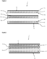
- FIG. 1 shows an exploded view of a CCM according to one embodiment of the invention.
- the CCM 1 consists of three individual catalyst-coated membrane components.
- a first membrane component 10 has a first face 10a and a second face 10b.
- a second membrane component 11 has a first face 11a and a second face 11b.
- a third membrane component 12 has a first face 12a and a second face 12b.
- a cathode catalyst layer 13 is located adjacent the first face 10a of the first membrane component 10. In practice, this layer is applied to the first face 10a of the first membrane component 10. The first face 10a of the first membrane component 10 faces outwards, so that the cathode catalyst layer 13 is located on an external surface of the CCM.
- An anode catalyst layer 14 is located adjacent the first face 11a of the second membrane component 11. In practice, this layer is applied to the first face 11 a of the second membrane component 11. The first face 11a of the second membrane component 11 faces outwards, so that the anode catalyst layer 14 is located on an external surface of the CCM - the opposite surface to the cathode catalyst layer.
- a recombination catalyst layer 15 is located adjacent the first face 12a of the third membrane component 12. In practice, this layer is applied to the first face 12a of the third membrane component 12. The recombination catalyst layer 15 is also located adjacent the second face 11b of the second membrane component 11. The recombination catalyst layer is therefore sandwiched between the second and third membrane components 11 and 12, and lies in a position which is closer to the anode catalyst layer than it is to the cathode catalyst layer.
- Figure 2 shows the same CCM as Figure 1 , assembled and in cross-section.
- FIG. 3 shows a process by which the first membrane component 10 may be coated with a cathode catalyst layer 13 while positioned on its backing sheet 13c.
- the membrane component is held in place using a heated vacuum bed (not shown) and the catalyst layer is deposited using an ultrasonic spray coater.
- the ultrasonic spray coater is represented by nozzle 20. The same process as shown in Figure 3 may be used to coat membrane components 11 and 12 with their respective catalyst layers.
- Figure 4 demonstrates the process by which the CCM of the invention may be prepared, showing the individual membrane components 10, 11 and 12 in position ready for lamination after being coated with the catalyst layers 13, 14 and 15 respectively.
- the first membrane component 10 is coated with cathode catalyst 13
- the second membrane component 11 is coated with anode catalyst 14
- the third membrane component 12 is coated with recombination catalyst 15.
- Figure 4 shows a process for laminating the three coated membrane components 10, 11 and 12 to form a discrete CCM 1.
- the backing sheets (not shown) are removed from each membrane component and the catalyst-coated membrane components are laid on top of one another in the correct order before being placed between two PTFE sheets 21, 22 and two titanium plates 23, 24 and pressed at temperature in a press pack.
- the central intermediate layer 12 is oriented such that the recombination catalyst layer 15 faces the second membrane component 11. This is because of the faster diffusion rate of H 2 relative to O 2 through the CCM.
- Orienting the membrane components in the manner shown means that, because the membrane components are of equal thickness, the recombination catalyst layer will be positioned closer to the anode catalyst layer in the final laminated CCM. As a result, the recombination catalyst layer will lie closer to the plane in which the levels of H 2 and O 2 are suitable for most effective recombination.
- the catalyst-coated membrane components When the catalyst-coated membrane components have been properly arranged they are laminated by heat pressing between the PTFE sheets 21, 22 and titanium plates 23, 24 at e.g. 170°C and 800 psi (approx. 5500 kPa) for 2 minutes to consolidate the catalyst-coated membrane components into the CCM 1 shown in cross-section in Figure 2 .
- suitable current collectors are positioned on each faces of the CCM to enable incorporation into a water electrolyser (PEMWE).
- PEMWE water electrolyser
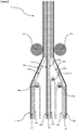
- Figure 5 shows an alternative, continuous process for the production of a CCM 3 according to the invention.
- the product of the process is a long sheet of CCM 3 which can be stored as a roll (not shown).
- the first, second and third membrane components 30, 31 and 32 are also long sheets which can be stored as rolls (not shown) before processing into the CCM.
- the process shown in Figure 5 is therefore the intermediate part of a roll-to-roll process.
- Membrane components 30, 31 and 32, coated with catalyst layers on each of their first face 30a, 31a and 32a respectively and backing sheets 30c, 31c and 32c respectively on the other face are shown in Figure 5 .
- Backing sheets 30c, 31c and 32c are removed from the membrane components 30, 31 and 32 by peeling the backing sheets 30c, 31c and 32c away from the membrane components 30, 31 and 32 and passing them over rollers 36a, 36b and 36c.
- the three membrane components 30, 31 and 32 coated with catalyst layers 30a, 31 a and 32a respectively are then brought together as they approach rollers 37a and 37b until they are brought into contact.
- the second face 30b of first membrane component 30 contacts the second face 32b of third membrane component 32.
- the second face 31b of second membrane component 31 contacts the first face 32a of third membrane component 32 (which is coated with recombination catalyst 35).
- the laminate structure is subjected to heat and pressure to consolidate the components into a CCM sheet 3, with a cathode catalyst layer 33 on one surface and an anode catalyst layer 34 on the other surface, and an internal recombination catalyst layer 35 within.
- the sheet 3 may then be formed into a roll (not shown) for storage and transportation, and/or cut into individual CCMs of appropriate size as needed.
- CCM 1 was prepared using three individual membrane components. Each membrane component had a nominal thickness of 17 ⁇ m, comprised a 900 EW FlemionTM ionomer from Asahi Glass Group with e-PTFE reinforcement and had a ceria hydrogen peroxide scavenger catalyst coated on one side. A cathode catalyst layer comprising Pt black in a dispersion of ionomer (aqueous Nafion 1100EW, 12 wt% w.r.t. Pt) was coated in an amount of 1 mgPt/cm 2 onto one of the membrane components, on top of the scavenger catalyst.
- aqueous Nafion 1100EW 12 wt% w.r.t. Pt
- An anode catalyst layer comprising IrO 2 black in a solution of ionomer (aqueous Nafion 1100EW from Chemours Corp, 12 wt% w.r.t. Ir) was coated in an amount of 2 mg Ir/cm 2 onto another of the membrane components, on top of the scavenger layer.
- a recombination catalyst comprising Pd supported on carbon black in a solution of ionomer (Nafion 1100EW, 300 wt% w.r.t. carbon) was deposited onto the final membrane component in an amount of 0.04 mg Pd/cm 2 , on top of the scavenger catalyst.
- the catalyst layers were deposited using an ultrasonic spray coater (Sonotek ExactCoat with 120kHz Impact coating head).
- the three catalyst-coated membrane components were then arranged with the membrane component having the recombination catalyst layer in the middle, sandwiched between the other two membrane components with the anode and cathode catalyst layers facing outwards.
- the central membrane component was oriented such that the recombination catalyst layer faced the membrane component which carried the anode catalyst layer (as in Figure 2 ).
- a cathode catalyst comprising Pt black in a solution of ionomer (aqueous Nafion 1100EW, 12 wt% w.r.t. Pt) was coated in an amount of 1 mgPt/cm 2 on one side of the Nafion 117 membrane and an anode catalyst comprising IrO 2 black in a solution of ionomer (aqueous Nafion 1100EW, 12 wt% w.r.t. Ir) was coated in an amount of 2 mg Ir/cm 2 on the other side, to provide CCM A.
- the catalysts were deposited using an ultrasonic spray coater (Sonotek ExactCoat with 120kHz Impact coating head).
- CCM B was prepared using three individual membrane components identical to those used for CCM 1, with e-PTFE reinforcement and a peroxide scavenger layer.
- the three membrane components were laminated to form a laminated membrane before being coated on one side with a cathode catalyst (as used in Membrane 1) and on the other side with an anode catalyst (as used in Membrane 1) to give CCM B.
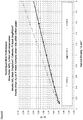
- Each CCM was tested at 60°C using an electrolyser test station and a QCF25 cell fixture from Baltic Fuel Cells with parallel flow fields machined out of carbon on the cathodic side and titanium anodic side.
- the CCMs were assembled between a carbon base gas diffusion layer on the cathodic side (SGL 10BB) and a gold coated porous titanium sinter (Mott) on the anodic side.
- the assembled MEA was then heated in place using the reactant water passing on the cathodic side which in turn was heated via a tube-in-tube heat exchanger and water bath.
- the polarisation curves were recorded from 2 A cm -2 down to 0.1 A cm -2 holding at each point for 170 s.
- the hydrogen in oxygen was measured after cooling the anode exhaust gas with a heat exchanger using a four port thermal conductivity detector (GE - XMTC) with pure oxygen as the reference gas and calibrated against a 10 % H 2 in N 2 reference gas and corrected for the different thermal conductivities of O 2 and N 2 .
- the crossover data was logged continuously and the final points at each current density reported.
- improved performance (lower applied voltages at a given current) is seen for both CCM B and CCM 1 due to the reduced thickness of both membranes relative to CCM A.
- the improved performance can be attributed to the reduced resistance of the CCM from the lowering of the gradient of the polarisation curves for CCM 1 and CCM B compared to CCM A.
- CCM 1 was the only membrane tested which demonstrated both good performance and acceptably low levels of hydrogen crossover.
Landscapes
- Chemical & Material Sciences (AREA)
- Engineering & Computer Science (AREA)
- Chemical Kinetics & Catalysis (AREA)
- Electrochemistry (AREA)
- Materials Engineering (AREA)
- Metallurgy (AREA)
- Organic Chemistry (AREA)
- General Chemical & Material Sciences (AREA)
- Manufacturing & Machinery (AREA)
- Life Sciences & Earth Sciences (AREA)
- Sustainable Development (AREA)
- Sustainable Energy (AREA)
- Inorganic Chemistry (AREA)
- Electrolytic Production Of Non-Metals, Compounds, Apparatuses Therefor (AREA)
- Inert Electrodes (AREA)
- Fuel Cell (AREA)
- Electrodes For Compound Or Non-Metal Manufacture (AREA)
- Catalysts (AREA)
Priority Applications (2)
| Application Number | Priority Date | Filing Date | Title |
|---|---|---|---|
| PL17818237T PL3559314T3 (pl) | 2016-12-22 | 2017-12-18 | Membrana powlekana katalizatorem mająca strukturę laminatu |
| EP21175035.1A EP3922757A1 (en) | 2016-12-22 | 2017-12-18 | Catalyst-coated membrane having a laminate structure |
Applications Claiming Priority (2)
| Application Number | Priority Date | Filing Date | Title |
|---|---|---|---|
| GBGB1621963.6A GB201621963D0 (en) | 2016-12-22 | 2016-12-22 | Catalyst-coated membrane having a laminate structure |
| PCT/GB2017/053775 WO2018115821A1 (en) | 2016-12-22 | 2017-12-18 | Catalyst-coated membrane having a laminate structure |
Related Child Applications (2)
| Application Number | Title | Priority Date | Filing Date |
|---|---|---|---|
| EP21175035.1A Division EP3922757A1 (en) | 2016-12-22 | 2017-12-18 | Catalyst-coated membrane having a laminate structure |
| EP21175035.1A Division-Into EP3922757A1 (en) | 2016-12-22 | 2017-12-18 | Catalyst-coated membrane having a laminate structure |
Publications (2)
| Publication Number | Publication Date |
|---|---|
| EP3559314A1 EP3559314A1 (en) | 2019-10-30 |
| EP3559314B1 true EP3559314B1 (en) | 2021-07-21 |
Family
ID=58360624
Family Applications (2)
| Application Number | Title | Priority Date | Filing Date |
|---|---|---|---|
| EP17818237.4A Active EP3559314B1 (en) | 2016-12-22 | 2017-12-18 | Catalyst-coated membrane having a laminate structure |
| EP21175035.1A Withdrawn EP3922757A1 (en) | 2016-12-22 | 2017-12-18 | Catalyst-coated membrane having a laminate structure |
Family Applications After (1)
| Application Number | Title | Priority Date | Filing Date |
|---|---|---|---|
| EP21175035.1A Withdrawn EP3922757A1 (en) | 2016-12-22 | 2017-12-18 | Catalyst-coated membrane having a laminate structure |
Country Status (11)
| Country | Link |
|---|---|
| US (1) | US11502308B2 (da) |
| EP (2) | EP3559314B1 (da) |
| JP (1) | JP6999673B2 (da) |
| KR (1) | KR102547602B1 (da) |
| CN (2) | CN110114512B (da) |
| AU (1) | AU2017381270B2 (da) |
| DK (1) | DK3559314T3 (da) |
| ES (1) | ES2890988T3 (da) |
| GB (1) | GB201621963D0 (da) |
| PL (1) | PL3559314T3 (da) |
| WO (1) | WO2018115821A1 (da) |
Cited By (1)
| Publication number | Priority date | Publication date | Assignee | Title |
|---|---|---|---|---|
| EP4610403A4 (en) * | 2022-12-27 | 2026-02-18 | Mitsubishi Heavy Ind Ltd | MEMBRANE-ELECTRODE ASSEMBLY AND METHOD FOR MANUFACTURING MEMBRANE-ELECTRODE ASSEMBLIES |
Families Citing this family (49)
| Publication number | Priority date | Publication date | Assignee | Title |
|---|---|---|---|---|
| WO2018185616A1 (en) * | 2017-04-03 | 2018-10-11 | 3M Innovative Properties Company | Water electrolyzers |
| US11329294B2 (en) * | 2018-03-22 | 2022-05-10 | Kabushiki Kaisha Toshiba | Laminated electrolyte membrane, membrane electrode assembly, water electrolysis cell, stack, water electrolyzer, and hydrogen utilizing system |
| US11560632B2 (en) * | 2018-09-27 | 2023-01-24 | 3M Innovative Properties Company | Membrane, membrane electrode assembly, and water electrolyzer including the same |
| KR102158604B1 (ko) * | 2018-11-02 | 2020-09-22 | 한국에너지기술연구원 | 기체방지투과층을 포함하는 알칼라인 수전해 셀 및 그 제조방법 |
| US20220407098A1 (en) * | 2021-06-16 | 2022-12-22 | Hydrolite Ltd | Self-refueling power-generating systems |
| GB201900646D0 (en) * | 2019-01-17 | 2019-03-06 | Johnson Matthey Fuel Cells Ltd | Membrane |
| CN110289433B (zh) * | 2019-06-21 | 2020-08-14 | 山东建筑大学 | 一种便于快速拆装的燃料电池夹具 |
| US11145875B2 (en) * | 2019-08-19 | 2021-10-12 | Robert Bosch Gmbh | Fuel cell electrode catalyst layer coating |
| CN110820007B (zh) * | 2019-11-14 | 2024-07-16 | 深圳大学 | 一种pbi质子交换膜电解模组及海水电解制氢装置 |
| CN111082078B (zh) * | 2019-12-30 | 2021-08-03 | 新源动力股份有限公司 | 一种高性能且抗电压反转的膜电极组件的制备方法 |
| WO2021157639A1 (ja) * | 2020-02-06 | 2021-08-12 | Agc株式会社 | 触媒層付きイオン交換膜、イオン交換膜および電解水素化装置 |
| US20230076096A1 (en) * | 2020-02-14 | 2023-03-09 | Linde Gmbh | Method and plant for the electrochemical production of oxygen |
| EP4204602A1 (en) * | 2020-09-02 | 2023-07-05 | University of South Carolina | Co-generation of high purity hydrogen and halide gases by electrolysis |
| DE102020126797A1 (de) * | 2020-10-13 | 2022-04-14 | Greenerity Gmbh | Katalysatorbeschichtete Membran und Wasserelektrolysezelle |
| KR20220061561A (ko) * | 2020-11-06 | 2022-05-13 | 현대자동차주식회사 | 복합 전해질막 및 이의 제조방법 |
| IL290023A (en) * | 2021-01-21 | 2022-08-01 | Hydrolite Ltd | Fabrication of membrane electrode assemblies and reversible electrochemical devices |
| AU2022216247A1 (en) * | 2021-02-02 | 2023-08-31 | Plug Power Inc. | Proton exchange membrane water electrolyzer membrane electrode assembly |
| WO2022177799A1 (en) * | 2021-02-19 | 2022-08-25 | Georgia Tech Research Corporation | Ionomers for improving the durability of membrane electrochemical devices and electrodes derived therefrom |
| WO2022244660A1 (ja) * | 2021-05-17 | 2022-11-24 | 東レ株式会社 | 電解質膜積層体、触媒層付電解質膜、膜電極接合体、水電解式水素発生装置および触媒層付電解質膜の製造方法 |
| KR20220163737A (ko) * | 2021-06-03 | 2022-12-12 | 현대자동차주식회사 | 화학적 내구성이 향상된 전해질막 및 이를 포함하는 막-전극 접합체 |
| CN117500956A (zh) * | 2021-06-14 | 2024-02-02 | W.L.戈尔及同仁股份有限公司 | 改进的电化学膜 |
| US11888196B2 (en) * | 2021-06-16 | 2024-01-30 | Hydrolite Ltd | Self-refueling power-generating systems |
| EP4112781A1 (de) * | 2021-06-30 | 2023-01-04 | Siemens Energy Global GmbH & Co. KG | Elektrolysezelle zur polymerelektrolytmembran-elektrolyse und verfahren zu deren herstellung |
| IL288000B (en) * | 2021-08-25 | 2022-09-01 | Hydrolite Ltd | Salt water electrolysis |
| GB202113634D0 (en) | 2021-09-24 | 2021-11-10 | Johnson Matthey Plc | Iridium-based oxygen evolution reaction catalyst |
| GB202113809D0 (en) | 2021-09-28 | 2021-11-10 | Johnson Matthey Plc | Catalyst coated proton exchange membranes for green hydrogen producing water electrolysers |
| WO2023052749A1 (en) | 2021-09-28 | 2023-04-06 | Johnson Matthey Public Limited Company | Catalyst coated proton exchange membranes for hydrogen producing water electrolysers |
| JP2024536518A (ja) * | 2021-10-14 | 2024-10-04 | アイガス エナジー ゲー・エム・ベー・ハー | 差圧電解による高圧水素製造用pem電解セルおよびpem電解セルスタック用フレーム |
| EP4166691A1 (de) * | 2021-10-14 | 2023-04-19 | iGas energy GmbH | Rahmen für pem elektrolysezellen und pem elektrolysezellen stapel zur erzeugung von hochdruck-wasserstoff mittels differenzdruckelektrolyse |
| WO2023129443A2 (en) * | 2021-12-27 | 2023-07-06 | Electric Hydrogen Co. | Multi-layered membranes for electrochemical cells |
| AU2023215814A1 (en) | 2022-02-04 | 2024-06-27 | Johnson Matthey Hydrogen Technologies Limited | Catalyst coated membranes for water electrolysers |
| WO2023172626A1 (en) * | 2022-03-08 | 2023-09-14 | Electric Hydrogen Co. | Methods, devices, and systems for mitigating hydrogen crossover within an electrochemical cell |
| GB202209514D0 (en) | 2022-06-29 | 2022-08-10 | Johnson Matthey Hydrogen Technologies Ltd | Membrane |
| JP7260045B1 (ja) | 2022-09-09 | 2023-04-18 | トヨタ自動車株式会社 | 水電解システム |
| JP7306548B1 (ja) | 2022-09-13 | 2023-07-11 | トヨタ自動車株式会社 | 膜電極接合体 |
| WO2024126749A1 (en) * | 2022-12-14 | 2024-06-20 | W. L. Gore & Associates, Inc. | Improved multi-layered proton exchange membrane for water electrolysis |
| DE102023200282A1 (de) * | 2023-01-16 | 2024-07-18 | Robert Bosch Gesellschaft mit beschränkter Haftung | Verfahren zur Herstellung einer elektrochemischen Zelle, elektrochemische Zelle, Brennstoffzellenstapel und Elektrolyseur |
| US20240263320A1 (en) * | 2023-02-07 | 2024-08-08 | Robert Bosch Gmbh | Polymer electrolyte water electrolyzer blocking material |
| DE102023107643A1 (de) | 2023-03-27 | 2024-10-02 | Greenerity Gmbh | Membranelektrodenanordnung und wasserelektrolysezelle |
| DE102023107644A1 (de) | 2023-03-27 | 2024-10-02 | Greenerity Gmbh | Membranelektrodenanordnung und wasserelektrolysezelle |
| DE102023107646A1 (de) * | 2023-03-27 | 2024-10-02 | Greenerity Gmbh | Membranelektrodenanordnung und verfahren zur herstellung derselben, brennstoffzelle und elektrolysezelle |
| WO2024238741A1 (en) * | 2023-05-18 | 2024-11-21 | The Lubrizol Corporation | Additives for improved electrolyzer durability |
| US20240426009A1 (en) * | 2023-06-23 | 2024-12-26 | Uop Llc | Proton exchange membrane and catalyst-coated proton exchange membrane |
| GB202314951D0 (en) | 2023-09-29 | 2023-11-15 | Johnson Matthey Hydrogen Technologies Ltd | Membrane |
| US20250174675A1 (en) | 2023-11-28 | 2025-05-29 | GM Global Technology Operations LLC | Membrane for electrochemical devices |
| US20250250694A1 (en) * | 2024-02-07 | 2025-08-07 | GM Global Technology Operations LLC | Membrane electrode assembly with graded gas recombination layer |
| GB202403351D0 (en) * | 2024-03-08 | 2024-04-24 | Johnson Matthey Hydrogen Technologies Ltd | Membrane |
| JP2025138161A (ja) * | 2024-03-11 | 2025-09-25 | 株式会社Screenホールディングス | 膜・触媒層接合体および水電解装置 |
| CN118704018A (zh) * | 2024-06-27 | 2024-09-27 | 华电重工股份有限公司 | 一种具有阳极催化层梯度结构的ccm及其制备方法和应用 |
Citations (1)
| Publication number | Priority date | Publication date | Assignee | Title |
|---|---|---|---|---|
| US20140116877A1 (en) * | 2011-06-17 | 2014-05-01 | Commissariat à l'énergie atomique et aux énergies alternatives | Membrane/electrode assembly for an electrolysis device |
Family Cites Families (24)
| Publication number | Priority date | Publication date | Assignee | Title |
|---|---|---|---|---|
| JP3271801B2 (ja) * | 1992-09-22 | 2002-04-08 | 田中貴金属工業株式会社 | 高分子固体電解質型燃料電池、該燃料電池の加湿方法、及び製造方法 |
| EP0631337B1 (en) | 1993-06-18 | 2000-07-12 | Tanaka Kikinzoku Kogyo K.K. | Electrochemical cell comprising solid polymer electrolyte composition. |
| GB9822576D0 (en) | 1998-10-16 | 1998-12-09 | Johnson Matthey Plc | Membrane |
| DE19917812C2 (de) * | 1999-04-20 | 2002-11-21 | Siemens Ag | Membranelektrodeneinheit für eine selbstbefeuchtende Brennstoffzelle, Verfahren zu ihrer Herstellung und Brennstoffzellenbatterie mit einer solchen Membranelektrodeneinheit |
| JP2005149939A (ja) * | 2003-11-17 | 2005-06-09 | Sony Corp | イオン伝導体及びその製造方法、並びに電気化学デバイス |
| DE102005038612A1 (de) * | 2005-08-16 | 2007-02-22 | Basf Ag | Verfahren zur Herstellung von beidseitig katalysatorbeschichteten Membranen |
| US7368200B2 (en) * | 2005-12-30 | 2008-05-06 | Tekion, Inc. | Composite polymer electrolyte membranes and electrode assemblies for reducing fuel crossover in direct liquid feed fuel cells |
| DE102006012908A1 (de) * | 2006-03-10 | 2007-09-13 | Deutsches Zentrum für Luft- und Raumfahrt e.V. | Elektroden-Membran-Einheit und Brennstoffzelle |
| KR100738062B1 (ko) * | 2006-05-16 | 2007-07-10 | 삼성에스디아이 주식회사 | 막 전극 접합체 및 이를 이용한 연료전지 |
| JP4323535B2 (ja) * | 2007-04-26 | 2009-09-02 | クロリンエンジニアズ株式会社 | 水電解装置 |
| GB0718620D0 (en) | 2007-09-25 | 2007-10-31 | Johnson Matthey Plc | Membrane electrode assembly |
| GB0804185D0 (en) | 2008-03-07 | 2008-04-16 | Johnson Matthey Plc | Ion-conducting membrane structures |
| CN101388463B (zh) * | 2008-10-23 | 2010-09-08 | 上海交通大学 | 质子交换膜水电解电池膜电极及其制备方法 |
| EP2467515B8 (en) * | 2009-08-19 | 2016-10-12 | Next Hydrogen Corporation | Proton exchange membrane water electrolyser module design |
| GB0921996D0 (en) * | 2009-12-17 | 2010-02-03 | Johnson Matthey Plc | Catayst layer assembley |
| JP5603928B2 (ja) * | 2010-03-23 | 2014-10-08 | 本田技研工業株式会社 | 電気化学装置 |
| WO2013185169A1 (en) * | 2012-06-12 | 2013-12-19 | Monash University | Gas permeable electrode and method of manufacture |
| GB201212229D0 (en) * | 2012-07-10 | 2012-08-22 | Johnson Matthey Plc | Ion-conducting membrance |
| JPWO2014087958A1 (ja) * | 2012-12-03 | 2017-01-05 | Jsr株式会社 | 膜−電極接合体の製造方法、膜−電極接合体、膜−電極接合体形成用積層体、固体高分子型燃料電池および水電解装置 |
| JP6343602B2 (ja) * | 2013-03-29 | 2018-06-13 | Jxtgエネルギー株式会社 | 電気化学還元装置および、芳香族化合物の水素化体の製造方法 |
| DE102013019341A1 (de) * | 2013-11-20 | 2015-05-21 | Forschungszentrum Jülich GmbH | Elektrochemische Elektrolysezelle sowie Verfahren zum Betreiben derselben |
| GB201408953D0 (en) * | 2014-05-20 | 2014-07-02 | Johnson Matthey Fuel Cells Ltd | Membrane electrode assembly |
| GB201415846D0 (en) | 2014-09-08 | 2014-10-22 | Johnson Matthey Fuel Cells Ltd | Catalyst |
| CN109690854B (zh) * | 2016-08-25 | 2023-08-22 | 质子能体系股份有限公司 | 膜电极组合件及其制造方法 |
-
2016
- 2016-12-22 GB GBGB1621963.6A patent/GB201621963D0/en not_active Ceased
-
2017
- 2017-12-18 JP JP2019532710A patent/JP6999673B2/ja active Active
- 2017-12-18 EP EP17818237.4A patent/EP3559314B1/en active Active
- 2017-12-18 PL PL17818237T patent/PL3559314T3/pl unknown
- 2017-12-18 KR KR1020197021003A patent/KR102547602B1/ko active Active
- 2017-12-18 WO PCT/GB2017/053775 patent/WO2018115821A1/en not_active Ceased
- 2017-12-18 US US16/472,503 patent/US11502308B2/en active Active
- 2017-12-18 CN CN201780078899.0A patent/CN110114512B/zh active Active
- 2017-12-18 EP EP21175035.1A patent/EP3922757A1/en not_active Withdrawn
- 2017-12-18 AU AU2017381270A patent/AU2017381270B2/en active Active
- 2017-12-18 DK DK17818237.4T patent/DK3559314T3/da active
- 2017-12-18 CN CN202110816279.0A patent/CN113529121A/zh active Pending
- 2017-12-18 ES ES17818237T patent/ES2890988T3/es active Active
Patent Citations (1)
| Publication number | Priority date | Publication date | Assignee | Title |
|---|---|---|---|---|
| US20140116877A1 (en) * | 2011-06-17 | 2014-05-01 | Commissariat à l'énergie atomique et aux énergies alternatives | Membrane/electrode assembly for an electrolysis device |
Cited By (1)
| Publication number | Priority date | Publication date | Assignee | Title |
|---|---|---|---|---|
| EP4610403A4 (en) * | 2022-12-27 | 2026-02-18 | Mitsubishi Heavy Ind Ltd | MEMBRANE-ELECTRODE ASSEMBLY AND METHOD FOR MANUFACTURING MEMBRANE-ELECTRODE ASSEMBLIES |
Also Published As
| Publication number | Publication date |
|---|---|
| DK3559314T3 (da) | 2021-10-04 |
| KR20190097210A (ko) | 2019-08-20 |
| AU2017381270B2 (en) | 2022-12-22 |
| ES2890988T3 (es) | 2022-01-25 |
| WO2018115821A1 (en) | 2018-06-28 |
| CN110114512B (zh) | 2021-08-10 |
| US20200099061A1 (en) | 2020-03-26 |
| US11502308B2 (en) | 2022-11-15 |
| EP3922757A1 (en) | 2021-12-15 |
| GB201621963D0 (en) | 2017-02-08 |
| JP2020514528A (ja) | 2020-05-21 |
| AU2017381270A1 (en) | 2019-06-13 |
| KR102547602B1 (ko) | 2023-06-27 |
| CN110114512A (zh) | 2019-08-09 |
| PL3559314T3 (pl) | 2021-12-13 |
| EP3559314A1 (en) | 2019-10-30 |
| CN113529121A (zh) | 2021-10-22 |
| JP6999673B2 (ja) | 2022-01-18 |
Similar Documents
| Publication | Publication Date | Title |
|---|---|---|
| EP3559314B1 (en) | Catalyst-coated membrane having a laminate structure | |
| EP3465806B1 (en) | Catalyst | |
| EP2774203B1 (en) | Method for the preparation of catalyst-coated membranes | |
| US9034134B2 (en) | Manufacturability of ePTFE laminated membranes | |
| WO2023052750A1 (en) | Catalyst coated proton exchange membranes for hydrogen producing water electrolysers | |
| US20260031366A1 (en) | Process and membrane | |
| EP4326925B1 (en) | Catalyst coated membranes for water electrolysers | |
| WO2023052749A1 (en) | Catalyst coated proton exchange membranes for hydrogen producing water electrolysers | |
| GB2640128A (en) | Catalyst-coated membranes for water electrolysis | |
| WO2024246487A1 (en) | Method of manufacturing a catalyst-coated ion-conducting membrane | |
| GB2637803A (en) | Method | |
| CN118591659A (zh) | 用于水电解槽的催化剂涂覆的膜 |
Legal Events
| Date | Code | Title | Description |
|---|---|---|---|
| STAA | Information on the status of an ep patent application or granted ep patent |
Free format text: STATUS: UNKNOWN |
|
| STAA | Information on the status of an ep patent application or granted ep patent |
Free format text: STATUS: THE INTERNATIONAL PUBLICATION HAS BEEN MADE |
|
| PUAI | Public reference made under article 153(3) epc to a published international application that has entered the european phase |
Free format text: ORIGINAL CODE: 0009012 |
|
| STAA | Information on the status of an ep patent application or granted ep patent |
Free format text: STATUS: REQUEST FOR EXAMINATION WAS MADE |
|
| 17P | Request for examination filed |
Effective date: 20190710 |
|
| AK | Designated contracting states |
Kind code of ref document: A1 Designated state(s): AL AT BE BG CH CY CZ DE DK EE ES FI FR GB GR HR HU IE IS IT LI LT LU LV MC MK MT NL NO PL PT RO RS SE SI SK SM TR |
|
| AX | Request for extension of the european patent |
Extension state: BA ME |
|
| DAV | Request for validation of the european patent (deleted) | ||
| DAX | Request for extension of the european patent (deleted) | ||
| STAA | Information on the status of an ep patent application or granted ep patent |
Free format text: STATUS: EXAMINATION IS IN PROGRESS |
|
| 17Q | First examination report despatched |
Effective date: 20200515 |
|
| REG | Reference to a national code |
Ref country code: DE Ref legal event code: R079 Ref document number: 602017042617 Country of ref document: DE Free format text: PREVIOUS MAIN CLASS: C25B0011040000 Ipc: C25B0001040000 |
|
| RIC1 | Information provided on ipc code assigned before grant |
Ipc: C25B 13/08 20060101ALI20210113BHEP Ipc: H01M 8/1018 20160101ALI20210113BHEP Ipc: H01M 8/04082 20160101ALI20210113BHEP Ipc: H01M 4/88 20060101ALI20210113BHEP Ipc: C25B 13/02 20060101ALI20210113BHEP Ipc: C25B 11/04 20210101AFI20210113BHEP |
|
| GRAP | Despatch of communication of intention to grant a patent |
Free format text: ORIGINAL CODE: EPIDOSNIGR1 |
|
| STAA | Information on the status of an ep patent application or granted ep patent |
Free format text: STATUS: GRANT OF PATENT IS INTENDED |
|
| RIC1 | Information provided on ipc code assigned before grant |
Ipc: C25B 1/04 20210101AFI20210204BHEP Ipc: H01M 8/1018 20160101ALI20210204BHEP Ipc: H01M 4/88 20060101ALI20210204BHEP Ipc: C25B 13/08 20060101ALI20210204BHEP Ipc: H01M 8/04082 20160101ALI20210204BHEP Ipc: C25B 9/77 20210101ALI20210204BHEP Ipc: C25B 13/02 20060101ALI20210204BHEP Ipc: C25B 11/081 20210101ALI20210204BHEP Ipc: C25B 9/23 20210101ALI20210204BHEP Ipc: C25B 11/097 20210101ALI20210204BHEP |
|
| INTG | Intention to grant announced |
Effective date: 20210222 |
|
| GRAS | Grant fee paid |
Free format text: ORIGINAL CODE: EPIDOSNIGR3 |
|
| GRAA | (expected) grant |
Free format text: ORIGINAL CODE: 0009210 |
|
| STAA | Information on the status of an ep patent application or granted ep patent |
Free format text: STATUS: THE PATENT HAS BEEN GRANTED |
|
| AK | Designated contracting states |
Kind code of ref document: B1 Designated state(s): AL AT BE BG CH CY CZ DE DK EE ES FI FR GB GR HR HU IE IS IT LI LT LU LV MC MK MT NL NO PL PT RO RS SE SI SK SM TR |
|
| REG | Reference to a national code |
Ref country code: GB Ref legal event code: FG4D |
|
| REG | Reference to a national code |
Ref country code: CH Ref legal event code: EP |
|
| REG | Reference to a national code |
Ref country code: DE Ref legal event code: R096 Ref document number: 602017042617 Country of ref document: DE |
|
| REG | Reference to a national code |
Ref country code: AT Ref legal event code: REF Ref document number: 1412694 Country of ref document: AT Kind code of ref document: T Effective date: 20210815 |
|
| REG | Reference to a national code |
Ref country code: IE Ref legal event code: FG4D |
|
| REG | Reference to a national code |
Ref country code: FI Ref legal event code: FGE |
|
| REG | Reference to a national code |
Ref country code: DK Ref legal event code: T3 Effective date: 20210929 |
|
| REG | Reference to a national code |
Ref country code: LT Ref legal event code: MG9D |
|
| REG | Reference to a national code |
Ref country code: AT Ref legal event code: MK05 Ref document number: 1412694 Country of ref document: AT Kind code of ref document: T Effective date: 20210721 |
|
| REG | Reference to a national code |
Ref country code: NL Ref legal event code: FP |
|
| REG | Reference to a national code |
Ref country code: NO Ref legal event code: T2 Effective date: 20210721 |
|
| REG | Reference to a national code |
Ref country code: ES Ref legal event code: FG2A Ref document number: 2890988 Country of ref document: ES Kind code of ref document: T3 Effective date: 20220125 |
|
| PG25 | Lapsed in a contracting state [announced via postgrant information from national office to epo] |
Ref country code: RS Free format text: LAPSE BECAUSE OF FAILURE TO SUBMIT A TRANSLATION OF THE DESCRIPTION OR TO PAY THE FEE WITHIN THE PRESCRIBED TIME-LIMIT Effective date: 20210721 Ref country code: SE Free format text: LAPSE BECAUSE OF FAILURE TO SUBMIT A TRANSLATION OF THE DESCRIPTION OR TO PAY THE FEE WITHIN THE PRESCRIBED TIME-LIMIT Effective date: 20210721 Ref country code: HR Free format text: LAPSE BECAUSE OF FAILURE TO SUBMIT A TRANSLATION OF THE DESCRIPTION OR TO PAY THE FEE WITHIN THE PRESCRIBED TIME-LIMIT Effective date: 20210721 Ref country code: PT Free format text: LAPSE BECAUSE OF FAILURE TO SUBMIT A TRANSLATION OF THE DESCRIPTION OR TO PAY THE FEE WITHIN THE PRESCRIBED TIME-LIMIT Effective date: 20211122 Ref country code: BG Free format text: LAPSE BECAUSE OF FAILURE TO SUBMIT A TRANSLATION OF THE DESCRIPTION OR TO PAY THE FEE WITHIN THE PRESCRIBED TIME-LIMIT Effective date: 20211021 Ref country code: AT Free format text: LAPSE BECAUSE OF FAILURE TO SUBMIT A TRANSLATION OF THE DESCRIPTION OR TO PAY THE FEE WITHIN THE PRESCRIBED TIME-LIMIT Effective date: 20210721 Ref country code: LT Free format text: LAPSE BECAUSE OF FAILURE TO SUBMIT A TRANSLATION OF THE DESCRIPTION OR TO PAY THE FEE WITHIN THE PRESCRIBED TIME-LIMIT Effective date: 20210721 |
|
| PG25 | Lapsed in a contracting state [announced via postgrant information from national office to epo] |
Ref country code: LV Free format text: LAPSE BECAUSE OF FAILURE TO SUBMIT A TRANSLATION OF THE DESCRIPTION OR TO PAY THE FEE WITHIN THE PRESCRIBED TIME-LIMIT Effective date: 20210721 Ref country code: GR Free format text: LAPSE BECAUSE OF FAILURE TO SUBMIT A TRANSLATION OF THE DESCRIPTION OR TO PAY THE FEE WITHIN THE PRESCRIBED TIME-LIMIT Effective date: 20211022 |
|
| REG | Reference to a national code |
Ref country code: DE Ref legal event code: R097 Ref document number: 602017042617 Country of ref document: DE |
|
| PLBE | No opposition filed within time limit |
Free format text: ORIGINAL CODE: 0009261 |
|
| STAA | Information on the status of an ep patent application or granted ep patent |
Free format text: STATUS: NO OPPOSITION FILED WITHIN TIME LIMIT |
|
| PG25 | Lapsed in a contracting state [announced via postgrant information from national office to epo] |
Ref country code: SM Free format text: LAPSE BECAUSE OF FAILURE TO SUBMIT A TRANSLATION OF THE DESCRIPTION OR TO PAY THE FEE WITHIN THE PRESCRIBED TIME-LIMIT Effective date: 20210721 Ref country code: SK Free format text: LAPSE BECAUSE OF FAILURE TO SUBMIT A TRANSLATION OF THE DESCRIPTION OR TO PAY THE FEE WITHIN THE PRESCRIBED TIME-LIMIT Effective date: 20210721 Ref country code: RO Free format text: LAPSE BECAUSE OF FAILURE TO SUBMIT A TRANSLATION OF THE DESCRIPTION OR TO PAY THE FEE WITHIN THE PRESCRIBED TIME-LIMIT Effective date: 20210721 Ref country code: EE Free format text: LAPSE BECAUSE OF FAILURE TO SUBMIT A TRANSLATION OF THE DESCRIPTION OR TO PAY THE FEE WITHIN THE PRESCRIBED TIME-LIMIT Effective date: 20210721 Ref country code: CZ Free format text: LAPSE BECAUSE OF FAILURE TO SUBMIT A TRANSLATION OF THE DESCRIPTION OR TO PAY THE FEE WITHIN THE PRESCRIBED TIME-LIMIT Effective date: 20210721 Ref country code: AL Free format text: LAPSE BECAUSE OF FAILURE TO SUBMIT A TRANSLATION OF THE DESCRIPTION OR TO PAY THE FEE WITHIN THE PRESCRIBED TIME-LIMIT Effective date: 20210721 |
|
| 26N | No opposition filed |
Effective date: 20220422 |
|
| PG25 | Lapsed in a contracting state [announced via postgrant information from national office to epo] |
Ref country code: MC Free format text: LAPSE BECAUSE OF FAILURE TO SUBMIT A TRANSLATION OF THE DESCRIPTION OR TO PAY THE FEE WITHIN THE PRESCRIBED TIME-LIMIT Effective date: 20210721 |
|
| REG | Reference to a national code |
Ref country code: CH Ref legal event code: PL |
|
| REG | Reference to a national code |
Ref country code: NO Ref legal event code: CHAD Owner name: JOHNSON MATTHEY HYDROGEN TECHNOLOGIES LIMITED, GB |
|
| REG | Reference to a national code |
Ref country code: NL Ref legal event code: HC Owner name: JOHNSON MATTHEY HYDROGEN TECHNOLOGIES LIMITED; GB Free format text: DETAILS ASSIGNMENT: CHANGE OF OWNER(S), CHANGE OF OWNER(S) NAME; FORMER OWNER NAME: JOHNSON MATTHEY FUEL CELLS LIMITED Effective date: 20220714 |
|
| REG | Reference to a national code |
Ref country code: FI Ref legal event code: PCE Owner name: JOHNSON MATTHEY HYDROGEN TECHNOLOGIES LIMITED |
|
| REG | Reference to a national code |
Ref country code: ES Ref legal event code: PC2A Owner name: JOHNSON MATTHEY HYDROGEN TECHNOLOGIES LIMITED Effective date: 20220912 |
|
| REG | Reference to a national code |
Ref country code: DE Ref legal event code: R081 Ref document number: 602017042617 Country of ref document: DE Owner name: JOHNSON MATTHEY HYDROGEN TECHNOLOGIES LIMITED, GB Free format text: FORMER OWNER: JOHNSON MATTHEY FUEL CELLS LIMITED, LONDON, GB |
|
| REG | Reference to a national code |
Ref country code: BE Ref legal event code: HC Owner name: JOHNSON MATTHEY HYDROGEN TECHNOLOGIES LIMITED; GB Free format text: DETAILS ASSIGNMENT: CHANGE OF OWNER(S), CHANGE OF OWNER(S) NAME; FORMER OWNER NAME: JOHNSON MATTHEY FUEL CELLS LIMITED Effective date: 20220722 |
|
| PG25 | Lapsed in a contracting state [announced via postgrant information from national office to epo] |
Ref country code: LU Free format text: LAPSE BECAUSE OF NON-PAYMENT OF DUE FEES Effective date: 20211218 Ref country code: IE Free format text: LAPSE BECAUSE OF NON-PAYMENT OF DUE FEES Effective date: 20211218 |
|
| PG25 | Lapsed in a contracting state [announced via postgrant information from national office to epo] |
Ref country code: LI Free format text: LAPSE BECAUSE OF NON-PAYMENT OF DUE FEES Effective date: 20211231 Ref country code: CH Free format text: LAPSE BECAUSE OF NON-PAYMENT OF DUE FEES Effective date: 20211231 |
|
| PG25 | Lapsed in a contracting state [announced via postgrant information from national office to epo] |
Ref country code: CY Free format text: LAPSE BECAUSE OF FAILURE TO SUBMIT A TRANSLATION OF THE DESCRIPTION OR TO PAY THE FEE WITHIN THE PRESCRIBED TIME-LIMIT Effective date: 20210721 |
|
| P01 | Opt-out of the competence of the unified patent court (upc) registered |
Effective date: 20230526 |
|
| PG25 | Lapsed in a contracting state [announced via postgrant information from national office to epo] |
Ref country code: HU Free format text: LAPSE BECAUSE OF FAILURE TO SUBMIT A TRANSLATION OF THE DESCRIPTION OR TO PAY THE FEE WITHIN THE PRESCRIBED TIME-LIMIT; INVALID AB INITIO Effective date: 20171218 |
|
| PGFP | Annual fee paid to national office [announced via postgrant information from national office to epo] |
Ref country code: NL Payment date: 20231121 Year of fee payment: 7 |
|
| PGFP | Annual fee paid to national office [announced via postgrant information from national office to epo] |
Ref country code: FI Payment date: 20231121 Year of fee payment: 7 Ref country code: DK Payment date: 20231121 Year of fee payment: 7 |
|
| PGFP | Annual fee paid to national office [announced via postgrant information from national office to epo] |
Ref country code: PL Payment date: 20231124 Year of fee payment: 7 Ref country code: BE Payment date: 20231121 Year of fee payment: 7 |
|
| PG25 | Lapsed in a contracting state [announced via postgrant information from national office to epo] |
Ref country code: MK Free format text: LAPSE BECAUSE OF FAILURE TO SUBMIT A TRANSLATION OF THE DESCRIPTION OR TO PAY THE FEE WITHIN THE PRESCRIBED TIME-LIMIT Effective date: 20210721 |
|
| PG25 | Lapsed in a contracting state [announced via postgrant information from national office to epo] |
Ref country code: MT Free format text: LAPSE BECAUSE OF FAILURE TO SUBMIT A TRANSLATION OF THE DESCRIPTION OR TO PAY THE FEE WITHIN THE PRESCRIBED TIME-LIMIT Effective date: 20210721 |
|
| PG25 | Lapsed in a contracting state [announced via postgrant information from national office to epo] |
Ref country code: FI Free format text: LAPSE BECAUSE OF NON-PAYMENT OF DUE FEES Effective date: 20241218 |
|
| REG | Reference to a national code |
Ref country code: DK Ref legal event code: EBP Effective date: 20241231 |
|
| REG | Reference to a national code |
Ref country code: NL Ref legal event code: MM Effective date: 20250101 |
|
| PG25 | Lapsed in a contracting state [announced via postgrant information from national office to epo] |
Ref country code: NL Free format text: LAPSE BECAUSE OF NON-PAYMENT OF DUE FEES Effective date: 20250101 |
|
| REG | Reference to a national code |
Ref country code: BE Ref legal event code: MM Effective date: 20241231 |
|
| PG25 | Lapsed in a contracting state [announced via postgrant information from national office to epo] |
Ref country code: BE Free format text: LAPSE BECAUSE OF NON-PAYMENT OF DUE FEES Effective date: 20241231 |
|
| PG25 | Lapsed in a contracting state [announced via postgrant information from national office to epo] |
Ref country code: TR Free format text: LAPSE BECAUSE OF FAILURE TO SUBMIT A TRANSLATION OF THE DESCRIPTION OR TO PAY THE FEE WITHIN THE PRESCRIBED TIME-LIMIT Effective date: 20210721 |
|
| PGFP | Annual fee paid to national office [announced via postgrant information from national office to epo] |
Ref country code: DE Payment date: 20251126 Year of fee payment: 9 |
|
| PGFP | Annual fee paid to national office [announced via postgrant information from national office to epo] |
Ref country code: GB Payment date: 20251119 Year of fee payment: 9 |
|
| PGFP | Annual fee paid to national office [announced via postgrant information from national office to epo] |
Ref country code: NO Payment date: 20251121 Year of fee payment: 9 |
|
| PG25 | Lapsed in a contracting state [announced via postgrant information from national office to epo] |
Ref country code: DK Free format text: LAPSE BECAUSE OF NON-PAYMENT OF DUE FEES Effective date: 20241231 |
|
| PGFP | Annual fee paid to national office [announced via postgrant information from national office to epo] |
Ref country code: IT Payment date: 20251119 Year of fee payment: 9 |
|
| PGFP | Annual fee paid to national office [announced via postgrant information from national office to epo] |
Ref country code: FR Payment date: 20251119 Year of fee payment: 9 |
|
| PGFP | Annual fee paid to national office [announced via postgrant information from national office to epo] |
Ref country code: ES Payment date: 20260102 Year of fee payment: 9 |
|
| PG25 | Lapsed in a contracting state [announced via postgrant information from national office to epo] |
Ref country code: PL Free format text: LAPSE BECAUSE OF NON-PAYMENT OF DUE FEES Effective date: 20241218 |