EP3559283B1 - Method for heating a blank and heating system - Google Patents
Method for heating a blank and heating system Download PDFInfo
- Publication number
- EP3559283B1 EP3559283B1 EP17829975.6A EP17829975A EP3559283B1 EP 3559283 B1 EP3559283 B1 EP 3559283B1 EP 17829975 A EP17829975 A EP 17829975A EP 3559283 B1 EP3559283 B1 EP 3559283B1
- Authority
- EP
- European Patent Office
- Prior art keywords
- blank
- preheating
- furnace
- heating
- temperature
- Prior art date
- Legal status (The legal status is an assumption and is not a legal conclusion. Google has not performed a legal analysis and makes no representation as to the accuracy of the status listed.)
- Active
Links
Images


Classifications
-
- C—CHEMISTRY; METALLURGY
- C21—METALLURGY OF IRON
- C21D—MODIFYING THE PHYSICAL STRUCTURE OF FERROUS METALS; GENERAL DEVICES FOR HEAT TREATMENT OF FERROUS OR NON-FERROUS METALS OR ALLOYS; MAKING METAL MALLEABLE, e.g. BY DECARBURISATION OR TEMPERING
- C21D1/00—General methods or devices for heat treatment, e.g. annealing, hardening, quenching or tempering
- C21D1/34—Methods of heating
-
- F—MECHANICAL ENGINEERING; LIGHTING; HEATING; WEAPONS; BLASTING
- F27—FURNACES; KILNS; OVENS; RETORTS
- F27B—FURNACES, KILNS, OVENS OR RETORTS IN GENERAL; OPEN SINTERING OR LIKE APPARATUS
- F27B9/00—Furnaces through which the charge is moved mechanically, e.g. of tunnel type; Similar furnaces in which the charge moves by gravity
- F27B9/14—Furnaces through which the charge is moved mechanically, e.g. of tunnel type; Similar furnaces in which the charge moves by gravity characterised by the path of the charge during treatment; characterised by the means by which the charge is moved during treatment
- F27B9/20—Furnaces through which the charge is moved mechanically, e.g. of tunnel type; Similar furnaces in which the charge moves by gravity characterised by the path of the charge during treatment; characterised by the means by which the charge is moved during treatment the charge moving in a substantially straight path
- F27B9/24—Furnaces through which the charge is moved mechanically, e.g. of tunnel type; Similar furnaces in which the charge moves by gravity characterised by the path of the charge during treatment; characterised by the means by which the charge is moved during treatment the charge moving in a substantially straight path being carried by a conveyor
-
- C—CHEMISTRY; METALLURGY
- C21—METALLURGY OF IRON
- C21D—MODIFYING THE PHYSICAL STRUCTURE OF FERROUS METALS; GENERAL DEVICES FOR HEAT TREATMENT OF FERROUS OR NON-FERROUS METALS OR ALLOYS; MAKING METAL MALLEABLE, e.g. BY DECARBURISATION OR TEMPERING
- C21D9/00—Heat treatment, e.g. annealing, hardening, quenching or tempering, adapted for particular articles; Furnaces therefor
- C21D9/0068—Heat treatment, e.g. annealing, hardening, quenching or tempering, adapted for particular articles; Furnaces therefor for particular articles not mentioned below
-
- C—CHEMISTRY; METALLURGY
- C21—METALLURGY OF IRON
- C21D—MODIFYING THE PHYSICAL STRUCTURE OF FERROUS METALS; GENERAL DEVICES FOR HEAT TREATMENT OF FERROUS OR NON-FERROUS METALS OR ALLOYS; MAKING METAL MALLEABLE, e.g. BY DECARBURISATION OR TEMPERING
- C21D9/00—Heat treatment, e.g. annealing, hardening, quenching or tempering, adapted for particular articles; Furnaces therefor
- C21D9/46—Heat treatment, e.g. annealing, hardening, quenching or tempering, adapted for particular articles; Furnaces therefor for sheet metals
-
- F—MECHANICAL ENGINEERING; LIGHTING; HEATING; WEAPONS; BLASTING
- F27—FURNACES; KILNS; OVENS; RETORTS
- F27B—FURNACES, KILNS, OVENS OR RETORTS IN GENERAL; OPEN SINTERING OR LIKE APPARATUS
- F27B9/00—Furnaces through which the charge is moved mechanically, e.g. of tunnel type; Similar furnaces in which the charge moves by gravity
- F27B9/14—Furnaces through which the charge is moved mechanically, e.g. of tunnel type; Similar furnaces in which the charge moves by gravity characterised by the path of the charge during treatment; characterised by the means by which the charge is moved during treatment
- F27B9/20—Furnaces through which the charge is moved mechanically, e.g. of tunnel type; Similar furnaces in which the charge moves by gravity characterised by the path of the charge during treatment; characterised by the means by which the charge is moved during treatment the charge moving in a substantially straight path
- F27B9/201—Furnaces through which the charge is moved mechanically, e.g. of tunnel type; Similar furnaces in which the charge moves by gravity characterised by the path of the charge during treatment; characterised by the means by which the charge is moved during treatment the charge moving in a substantially straight path walking beam furnace
- F27B9/202—Conveyor mechanisms therefor
-
- F—MECHANICAL ENGINEERING; LIGHTING; HEATING; WEAPONS; BLASTING
- F27—FURNACES; KILNS; OVENS; RETORTS
- F27B—FURNACES, KILNS, OVENS OR RETORTS IN GENERAL; OPEN SINTERING OR LIKE APPARATUS
- F27B9/00—Furnaces through which the charge is moved mechanically, e.g. of tunnel type; Similar furnaces in which the charge moves by gravity
- F27B9/14—Furnaces through which the charge is moved mechanically, e.g. of tunnel type; Similar furnaces in which the charge moves by gravity characterised by the path of the charge during treatment; characterised by the means by which the charge is moved during treatment
- F27B9/20—Furnaces through which the charge is moved mechanically, e.g. of tunnel type; Similar furnaces in which the charge moves by gravity characterised by the path of the charge during treatment; characterised by the means by which the charge is moved during treatment the charge moving in a substantially straight path
- F27B9/24—Furnaces through which the charge is moved mechanically, e.g. of tunnel type; Similar furnaces in which the charge moves by gravity characterised by the path of the charge during treatment; characterised by the means by which the charge is moved during treatment the charge moving in a substantially straight path being carried by a conveyor
- F27B9/2407—Furnaces through which the charge is moved mechanically, e.g. of tunnel type; Similar furnaces in which the charge moves by gravity characterised by the path of the charge during treatment; characterised by the means by which the charge is moved during treatment the charge moving in a substantially straight path being carried by a conveyor the conveyor being constituted by rollers (roller hearth furnace)
-
- F—MECHANICAL ENGINEERING; LIGHTING; HEATING; WEAPONS; BLASTING
- F27—FURNACES; KILNS; OVENS; RETORTS
- F27D—DETAILS OR ACCESSORIES OF FURNACES, KILNS, OVENS OR RETORTS, IN SO FAR AS THEY ARE OF KINDS OCCURRING IN MORE THAN ONE KIND OF FURNACE
- F27D3/00—Charging; Discharging; Manipulation of charge
- F27D3/02—Skids or tracks for heavy objects
- F27D3/026—Skids or tracks for heavy objects transport or conveyor rolls for furnaces; roller rails
-
- C—CHEMISTRY; METALLURGY
- C21—METALLURGY OF IRON
- C21D—MODIFYING THE PHYSICAL STRUCTURE OF FERROUS METALS; GENERAL DEVICES FOR HEAT TREATMENT OF FERROUS OR NON-FERROUS METALS OR ALLOYS; MAKING METAL MALLEABLE, e.g. BY DECARBURISATION OR TEMPERING
- C21D2221/00—Treating localised areas of an article
Definitions
- the present disclosure relates to heating systems, in particular to heating systems comprising a preheating system.
- the present disclosure further relates to methods for manufacturing steel components including hot forming of blanks.
- Hot stamping is a process which allows manufacturing hot formed structural components with specific properties which may include features such as a high strength, reduced thickness of components and lightness.
- a furnace system heats steel blanks at a predetermined temperature, e.g. above an austenization temperature, particularly above Ac3 and softens the blanks to be hot formed. As the blanks exit the furnace, the blanks may be centered on a centering table to correctly place the heated blanks before being transferred to the press tool.
- a conveyor system in such a production line is configured to convey blanks to and through a furnace.
- the furnace and the conveyor system are configured such that the blanks are heated to a desired temperature and for a desired time period (e.g. 3-10 minutes) before exiting the furnace.
- the transportation of the components through the furnace takes place on e.g. roller conveyors.
- the preheating step may comprise preheating at least the thickest zone of the blank.
- the preheating step may comprise preheating the whole blank to a first temperature and preheating at least the thickest zone of the blank to a second temperature, wherein the second temperature is higher than the first temperature.
- the preheating step may be done in 25 seconds or less, preferably in 10 seconds or less.
- the method may further comprise transferring the heated blank to a press tool, hot deforming the blank and quenching the blank.
- a heating system for heating blanks in a production line according to claim 12 is provided.
- the preheating system As the preheating system is placed just before the furnace i.e. not in a separate preheating system, the temperature of the preheated zones is not decreased as a consequence of being transferred from the preheating system to the furnace, which involves a homogeneous heating when exiting the furnace. Additionally, no extra time is added to the process as the preheating process uses the time that the blank remains in the conveyor system to preheat the preselected zones. The heating process can thus be improved, or optimized.
- the heating system may comprise stopping elements to retain the blank at the predetermined location, wherein said stopping elements are retractable pins configured to be displaceable in an up-and-down motion or elevating bars configured to lift the blank perpendicularly to a conveying direction.
- the preheating system may comprise a base, at least one heating element and a support structure.
- the heating elements may be infrared, induction, flame, fluid or electric heaters.
- Figure 1 shows a blank 1 in a production line 100.
- the production line 100 may be e.g. a hot deformation or hot stamping production line which may comprise a conveyor system 120 to transport the blank 1 though the production line 100.
- the conveyor system 120 may comprise e.g. a plurality of conveyor rollers, parallel conveyor belts or walking beams.
- the conveyor system 120 in such a case may be driven using e.g. motors. In this case, the speed of the conveyor system 120 may be controlled by controlling the speed of the motors.
- the conveyor system 120 may comprise a feeding system and a furnace conveyor system to transport the bank through the furnace.
- the blank 1 may be placed in the conveyor system 120 by e.g. an industrial transfer robot (not shown) e.g. after being cut from a steel coil, and may be conveyed to a preheating system 110.
- an industrial transfer robot not shown
- the preheating system 110 may comprise a plurality of heating elements 111 arranged in a base 112 to preheat the blank 1 before entering the furnace.
- the base 112 of the preheating system 110 may be of any suitable size and shape, which may be determined e.g. by the dimensions of the blank. Accordingly, the number, size and shape of heating elements 111 may vary depending on e.g. the blank size or the desired blank configuration.
- a further support structure 113 may be used to fix the base 112 of the preheating system 110 to the floor. In other examples the support structure may be e.g. be coupled to the conveyor system, suspended from the ceiling or anchored to a wall.
- a centering table 140 may comprise a plurality of centering pins 141 which can be passive or can be actively moved to correctly position and center the blank 1.
- the blank 1 may be transferred to a press tool 150 for deforming and quenching.
- the blank 1 may be transferred to the press tool 150 by a transferring system (not shown), e.g. an industrial transfer robot, which may pick up the blank 1 from the conveyor system 120 and may place it on the pressing tool 150.
- the transfer robot may comprise a plurality of gripping units to grab and pick up the blank 1 from the conveyor means 120.
- the pressing tool 150 may be provided with cooling means (not shown) e.g. water supplies or any other suitable means, to quench the blank 1 simultaneously to the hot deforming process.
- the cooling or quenching may be done homogeneously for the whole blank 1.
- channels may be provided in the dies of the press tool through which cold water or other liquid may be conducted. This cools the contact surfaces of the press tool so that the blank is quenched.
- Figures 2a - 2d show the blank 1 in a predetermined preheating location, e.g. under the preheating system, in which the blank 1 may be subjected to a preheating process.
- the blank 1 may be retained in the predetermined preheating location e.g. where the preheating system overlaps substantially the whole blank or at least the preselected zone to be preheated, during the entire preheating process.
- the blank 1 may be preheated about 15 seconds or less at a temperature between 600 - 700 °C. During the preheating process the blank 1 may still in the predetermined preheating location.
- the blank 1 is retained in a predetermined preheating location by stopping the conveyor system 120 e.g. a conveyor belt.
- the blank 1 would firstly be conveyed to the predetermined preheating location.
- the blank would be retained in that position, i.e. predetermined preheating location, by stopping the conveyor system e.g. stopping the motion of the conveyor belt(s).
- the blank would then be preheated, and finally, once the preheating process has finished, the blank would be conveyed to the furnace.
- a conveyor system comprising conveyor rollers o walking beams may alternatively be used.
- the conveyor system is stopped by avoiding the upward and forward movement of the walking beams or the rotation of the conveyor rollers.
- the conveyor system 120 may be programmed to stop its movement when the blank is detected in the appropriate position e.g. by using sensors. In other examples the conveyor system may be programmed to stop periodically e.g. every 15 - 30 seconds.
- Figures 2b and 2c show a lateral view and a top view respectively of a conveyor system 120, e.g. conveyor rollers or walking beams, which may comprise at least a stopping element configured to retain the blank in the predetermined preheating location.
- a conveyor system 120 e.g. conveyor rollers or walking beams
- Such stopping elements may be retractable pins 122.
- the retractable pins 122 may be configured to be up-and-down displaceable for retaining the blank 1 in a predetermined preheating location i.e. avoiding its forward movement in the conveying direction (indicated by the x axis).
- a difference between this example and the example of Figure 2a is that the conveyor system 120 of Figures 2b and 2c may be operating at a substantially constant speed. As only the blank that is preheated is stopped, there is no need to interrupt the operation of the other blanks.
- the retractable pins 122 may be retracted e.g. under the conveyor system 120, until the blank 1 is detected e.g. by sensors.
- the retractable pins 122 may be configured to move up to retain the blank 1 when the blank 1 is detected in an adequate location, i.e. a predetermined preheating location.
- the retractable pins 122 may be in the "up" position, i.e. totally protruding, before and during the preheating process. In the same way, the retractable pins 122 may be configured to retract after the preheating process has finished, and so, the blank 1 may be conveyed to the furnace.
- Figure 2d shows another example to retain the blank 1 in a predetermined preheating location.
- the stopping elements or stops may be elevating bars 123 configured to displace the blank 1 perpendicularly to a conveying direction x.
- the elevating bars 123 may be located interleaved with the conveyor system 120 e.g. a plurality of conveyor belts or conveyor rollers, so as to avoid blocking the movement of the conveyor system 120.
- the elevating bars 123 may be configured to be perpendicularly displaceable (indicated by the y axis) to the conveying direction when the bank 1 is detected, e.g. by sensors, in a predetermined preheating location.
- the elevating bars 123 may be "hidden", i.e. retracted, until the blank 1 is in a predetermined preheating location. At that time, the elevating bars 123 would project outwardly and the blank 1 would therefore be perpendicularly displaced from the conveyor system 120 i.e. it would be elevated above the conveyor system (while the conveyor continues operating).
- the blank 1 may then be subjected to a preheating process. After the preheating process, the elevating bars 123 may be retracted and thus, the blank 1 may be placed onto the conveyor system 120 to be conveyed to the furnace.
- Figure 3a depicts a rectangular blank 300 which has been preheated at T 1 temperature, e.g. 630°C.
- T 1 temperature e.g. 630°C.
- the heating process may be optimized as the blanks may stay less time in the furnace.
- the furnace length may be decreased which, at least, reduces the energy consumption and the space taken up by the furnace.
- Figure 3b shows a rectangular blank, the central zone 310 of which has been preheated to T 1 temperature.
- the preheated zone 310 may correspond to e.g. the thickest zone of the blank.
- each zone may be preheated at a different temperature.
- Figure 3c illustrates a rectangular blank with three zones of different thicknesses, and wherein the temperature at which each zone has been preheated is different.
- a first zone 320 may be preheated at T 1
- a second zone 330 which may correspond to the thickest zone of the blank, may be heated at T 2 e.g. between 600 - 700 °C and finally, a third zone 340, which may correspond to the thinner zone of the blank, may not be heated.
- Temperature T 2 corresponding to the second zone, i.e. the thickest zone of the blank is therefore higher than the T 1 corresponding to the first zone.
- the whole blank may be preheated at T 1 while a predetermined zone, e.g. the thickest zone of the blank, may be preheated at T 2 , wherein T 2 is higher than T 1 .
- the blank may be made of different materials (e.g. different types of steels) which may e.g. have different thermal conductivities. Each material may therefore need to be heated for a specific heating time to reach a predetermined temperature. In such cases the different material areas may be heated at different temperatures.
- Figures 4a depicts a preheating system 110 comprising a rectangular base 112 and heating elements 111a arranged on it. In the depicted example, all the heating elements 111a are switched on, and therefore the whole blank would be preheated (see Figure 3a ).
- the blank may be selectively preheated.
- Figure 4b shows an example of a preheating system 110 wherein the heating elements 111a, 111b may be configured to selectively turn on and off for locally preheating only preselected zones of the blank, and thereby a heating pattern is created. In the example of Figure 4b only a central zone of the blank would be preheated (see Figure 3b ).
- the pattern may be formed by arranging the heating elements 111a, 111b in a predetermined manner (not shown) or it may be created by selectively switching off certain heating elements 111b while leaving other heating elements 111a switched on as shown in Figure 4b .
- the switched on heating elements 111a preheat preselected zones of the blank at a desired temperature, for example at a temperature between 600 - 700 °C.
- the amount of heat delivered by the heating elements 111a that are switched on may be regulated, e.g. controlling the power of the heating elements, so that different temperatures may be achieved.
- a tailored heating pattern taking into account e.g. the dimensions of the blank and/or the position of the preselected zone of the blank to be preheated, can be provided.
- the heating elements 111a, 111b may be infrared heaters, particularly infrared heating lamps.
- induction heaters, flame or hot air directed to the blank may be used.
- the blank may be heated by contacting a heating plate which is heated by electric heaters embedded in the heating plate or by a hot fluid, e.g. water, oil, etc., flowing through channels.
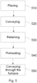
- Figure 5 shows a method to manufacture a steel component from a blank with zones of different thickness according to an example.
- a blank may be placed 510 in a conveyor system e.g. by an industrial transfer robot.
- the blank may be then conveyed 520 to a suitable preheating location, i.e. in a proper position with respect to a preheating system.
- the blank may be retained 530 in such position e.g. by stopping the conveyor system or by stops or stopping elements as described before.
- the blank, or at least a preselected zone of the blank and in particular a zone of the blank that has increased thickness may then be preheated 540 e.g. at a temperature of about 600 - 700 °C during less than 15 seconds.
- the blank may be conveyed through the furnace 550 to be heated e.g. at a temperature above Ac3.
- the blank may be in the furnace for about 3 minutes.
- the heated blank may exit the furnace and may be centered and correctly positioned in a centering system e.g. centering table, arranged downstream.
- the blank may then be transferred to a press tool e.g. by an industrial transfer robot, where it may be hot deformed to obtain (almost) the final shape.
- the blank may also be entirely or partially quenched in the press tool e.g. by supplying cold water.
- the blank may further be subjected to post processing steps such as e.g. cutting, trimming, and/or joining to further components using e.g. welding.
Landscapes
- Engineering & Computer Science (AREA)
- Chemical & Material Sciences (AREA)
- Mechanical Engineering (AREA)
- Materials Engineering (AREA)
- Crystallography & Structural Chemistry (AREA)
- Thermal Sciences (AREA)
- Physics & Mathematics (AREA)
- Metallurgy (AREA)
- Organic Chemistry (AREA)
- General Engineering & Computer Science (AREA)
- Heat Treatment Of Articles (AREA)
- Heat Treatments In General, Especially Conveying And Cooling (AREA)
- Shaping Metal By Deep-Drawing, Or The Like (AREA)
Applications Claiming Priority (2)
| Application Number | Priority Date | Filing Date | Title |
|---|---|---|---|
| EP16382645 | 2016-12-22 | ||
| PCT/EP2017/084119 WO2018115298A1 (en) | 2016-12-22 | 2017-12-21 | Method for heating a blank and heating system |
Publications (2)
| Publication Number | Publication Date |
|---|---|
| EP3559283A1 EP3559283A1 (en) | 2019-10-30 |
| EP3559283B1 true EP3559283B1 (en) | 2024-11-27 |
Family
ID=57749805
Family Applications (1)
| Application Number | Title | Priority Date | Filing Date |
|---|---|---|---|
| EP17829975.6A Active EP3559283B1 (en) | 2016-12-22 | 2017-12-21 | Method for heating a blank and heating system |
Country Status (6)
| Country | Link |
|---|---|
| US (2) | US11740023B2 (https=) |
| EP (1) | EP3559283B1 (https=) |
| JP (1) | JP2020507472A (https=) |
| CN (1) | CN110036121A (https=) |
| ES (1) | ES3013235T3 (https=) |
| WO (1) | WO2018115298A1 (https=) |
Families Citing this family (8)
| Publication number | Priority date | Publication date | Assignee | Title |
|---|---|---|---|---|
| DE102015215179A1 (de) * | 2015-08-07 | 2017-02-09 | Schwartz Gmbh | Verfahren zur Wärmebehandlung und Wärmebehandlungsvorrichtung |
| EP3559283B1 (en) * | 2016-12-22 | 2024-11-27 | Autotech Engineering S.L. | Method for heating a blank and heating system |
| DE102017211076B4 (de) * | 2017-06-29 | 2019-03-14 | Thyssenkrupp Ag | Verfahren zum Herstellen eines mit einem Überzug versehenen Stahlbauteils und Stahlbauteil |
| CN111167884B (zh) * | 2020-01-07 | 2020-12-29 | 燕山大学 | 一种用于中厚板矫直的装置及矫直方法 |
| KR102372480B1 (ko) * | 2020-03-27 | 2022-03-08 | 현대제철 주식회사 | 테일러 롤드 블랭크, 테일러 롤드 블랭크를 이용한 핫스탬핑 부품 제조방법 및 이에 의해 제조된 핫스탬핑 부품 |
| DE102020129506A1 (de) * | 2020-11-09 | 2022-05-12 | Ebner Industrieofenbau Gmbh | Zentrierungsvorrichtung für Metallplatinen |
| WO2025021939A1 (en) | 2023-07-26 | 2025-01-30 | Autotech Engineering, S.L. | Method for heating a blank and heating system |
| JP7511075B1 (ja) * | 2023-12-12 | 2024-07-04 | 中外炉工業株式会社 | 前処理装置 |
Citations (1)
| Publication number | Priority date | Publication date | Assignee | Title |
|---|---|---|---|---|
| CN102482725A (zh) * | 2009-07-24 | 2012-05-30 | 蒂森克虏伯钢铁欧洲股份公司 | 用于进行能量高效的热成型处理的方法和装置 |
Family Cites Families (36)
| Publication number | Priority date | Publication date | Assignee | Title |
|---|---|---|---|---|
| JPS57191728U (https=) * | 1981-05-29 | 1982-12-04 | ||
| JPH0252093U (https=) * | 1988-10-04 | 1990-04-13 | ||
| JP3317711B2 (ja) * | 1991-10-17 | 2002-08-26 | 石川島播磨重工業株式会社 | コイル焼鈍炉 |
| JP3312835B2 (ja) * | 1995-10-27 | 2002-08-12 | ロザイ工業株式会社 | 移動炉の固定装置 |
| US6019211A (en) * | 1996-01-18 | 2000-02-01 | Omtec Corporation | Conveyor and workstation |
| DE19653543A1 (de) * | 1996-12-20 | 1998-06-25 | Audi Ag | Verfahren zum Herstellen eines Blechformteiles durch Tiefziehen |
| JP2001241855A (ja) * | 1999-12-20 | 2001-09-07 | Ngk Insulators Ltd | 連続加熱炉 |
| JP4604364B2 (ja) * | 2001-02-22 | 2011-01-05 | 住友金属工業株式会社 | 金属板の熱間プレス方法およびその装置 |
| JP2003226914A (ja) * | 2002-02-04 | 2003-08-15 | Jfe Steel Kk | 厚鋼板の熱処理方法及び熱処理装置 |
| JP4890416B2 (ja) * | 2007-10-18 | 2012-03-07 | アイシン高丘株式会社 | ダイクエンチ工法におけるプレス加工装置及びプレス加工方法 |
| DE102008055980A1 (de) * | 2008-04-17 | 2009-10-29 | Schwartz, Eva | Verfahren und Durchlaufofen zum Erwärmen von Werkstücken |
| DE102008030279A1 (de) * | 2008-06-30 | 2010-01-07 | Benteler Automobiltechnik Gmbh | Partielles Warmformen und Härten mittels Infrarotlampenerwärmung |
| KR101045839B1 (ko) * | 2008-10-02 | 2011-07-01 | 주식회사 엠에스 오토텍 | 핫스탬핑용 가열로 장치 |
| DE102009014670B4 (de) | 2009-03-27 | 2011-01-13 | Thyssenkrupp Sofedit S.A.S | Verfahren und Warmumformanlage zur Herstellung von pressgehärteten Formbauteilen aus Stahlblech |
| DE102010004081C5 (de) * | 2010-01-06 | 2016-11-03 | Benteler Automobiltechnik Gmbh | Verfahren zum Warmformen und Härten einer Platine |
| US20110283851A1 (en) * | 2010-05-21 | 2011-11-24 | Thyssenkrupp Sofedit S.A.S. | Method and hot forming system for producing press-hardened formed components of sheet steel |
| JP2011255413A (ja) * | 2010-06-11 | 2011-12-22 | Toyoda Iron Works Co Ltd | 鋼板の加熱装置、プレス成形品の製造方法、およびプレス成形品 |
| ES2635765T5 (es) * | 2011-03-10 | 2020-09-28 | Schwartz Gmbh | Sistema de horno y procedimiento para el calentamiento parcial de piezas de chapa de acero |
| US20140045130A1 (en) * | 2011-06-30 | 2014-02-13 | Ebner Industrieofenbau Gmbh | Method for heating a shaped component for a subsequent press hardening operation and continuous furnace for regionally heating a shaped component preheated to a predetermined temperature to a higher temperature |
| KR101682868B1 (ko) | 2011-07-21 | 2016-12-05 | 가부시키가이샤 고베 세이코쇼 | 열간 프레스 성형 강 부재의 제조 방법 |
| CN103687795B (zh) * | 2011-07-21 | 2016-05-11 | 蒂森克虏伯系统工程股份有限公司 | 用于在传送装置上停止和/或对准运输货物的器件和方法以及传送装置 |
| EP2615396A1 (en) * | 2011-12-08 | 2013-07-17 | Linde Aktiengesellschaft | Assembly and method for pre-heating circuit boards for thermoforming |
| JP5838823B2 (ja) * | 2012-01-16 | 2016-01-06 | マツダ株式会社 | 通電加熱方法、通電加熱装置及び熱間プレス成形方法 |
| JP5987420B2 (ja) * | 2012-04-02 | 2016-09-07 | マツダ株式会社 | 通電加熱方法及び熱間プレス成形方法 |
| JP2014011296A (ja) * | 2012-06-29 | 2014-01-20 | Toppan Printing Co Ltd | ガラス基板搬送装置 |
| US9308564B2 (en) * | 2012-11-28 | 2016-04-12 | Magna International Inc. | Hot stamping system and method |
| KR101884103B1 (ko) * | 2014-01-30 | 2018-07-31 | 신닛테츠스미킨 카부시키카이샤 | 강판 가열 방법 및 강판 가열 장치 |
| JP2015208766A (ja) * | 2014-04-28 | 2015-11-24 | 川崎重工業株式会社 | スピニング成形装置 |
| DE102014110415B4 (de) * | 2014-07-23 | 2016-10-20 | Voestalpine Stahl Gmbh | Verfahren zum Aufheizen von Stahlblechen und Vorrichtung zur Durchführung des Verfahrens |
| CN104498702A (zh) * | 2014-09-03 | 2015-04-08 | 周玉杰 | 一种步进式加热炉及其使用方法 |
| CN104561515B (zh) * | 2015-01-26 | 2016-10-05 | 河北星烁锯业股份有限公司 | 连续式板坯加热炉及其加热方法 |
| JP2016173186A (ja) * | 2015-03-16 | 2016-09-29 | ダイハツ工業株式会社 | 加熱炉 |
| EP3156146B1 (en) * | 2015-10-13 | 2018-03-14 | Autotech Engineering, A.I.E. | Centering system for blanks |
| CN105316463A (zh) * | 2015-11-13 | 2016-02-10 | 嘉兴中岳热处理科技有限公司 | 一种可调式燃气加热式网带炉 |
| BR112018074046A2 (pt) * | 2016-08-09 | 2019-02-26 | Autotech Engineering A.I.E | sistema de centralização e método para produzir um componente de aço |
| EP3559283B1 (en) * | 2016-12-22 | 2024-11-27 | Autotech Engineering S.L. | Method for heating a blank and heating system |
-
2017
- 2017-12-21 EP EP17829975.6A patent/EP3559283B1/en active Active
- 2017-12-21 CN CN201780073236.XA patent/CN110036121A/zh active Pending
- 2017-12-21 JP JP2019528868A patent/JP2020507472A/ja active Pending
- 2017-12-21 ES ES17829975T patent/ES3013235T3/es active Active
- 2017-12-21 US US16/463,201 patent/US11740023B2/en active Active
- 2017-12-21 WO PCT/EP2017/084119 patent/WO2018115298A1/en not_active Ceased
-
2023
- 2023-07-14 US US18/222,412 patent/US12163737B2/en active Active
Patent Citations (1)
| Publication number | Priority date | Publication date | Assignee | Title |
|---|---|---|---|---|
| CN102482725A (zh) * | 2009-07-24 | 2012-05-30 | 蒂森克虏伯钢铁欧洲股份公司 | 用于进行能量高效的热成型处理的方法和装置 |
Also Published As
| Publication number | Publication date |
|---|---|
| CN110036121A (zh) | 2019-07-19 |
| ES3013235T3 (en) | 2025-04-11 |
| WO2018115298A1 (en) | 2018-06-28 |
| JP2020507472A (ja) | 2020-03-12 |
| US20230358473A1 (en) | 2023-11-09 |
| EP3559283A1 (en) | 2019-10-30 |
| US20190376745A1 (en) | 2019-12-12 |
| US12163737B2 (en) | 2024-12-10 |
| US11740023B2 (en) | 2023-08-29 |
Similar Documents
| Publication | Publication Date | Title |
|---|---|---|
| US12163737B2 (en) | Method for heating a blank and heating system | |
| EP2658663B1 (en) | Method of manufacturing multi physical properties part | |
| US9493856B2 (en) | Furnace system for the controlled heat treatment of sheet metal components | |
| CN109072322B (zh) | 具有至少两个强度不同的区域的汽车组件的制备方法 | |
| US8056383B2 (en) | Method of reheating steel part | |
| EP3497254B1 (en) | Centering and selective heating of blanks | |
| CN101688264B (zh) | 制造局部硬化的成型件的方法、局部硬化的成型件以及局部硬化的成型件的应用 | |
| CN105358718B (zh) | 用于制造加压淬火的钢板构件的方法和设备 | |
| CN103189153B (zh) | 滚压成形型材的方法和由此生产的结构件 | |
| CN108213862B (zh) | 车体部件制造方法 | |
| US20160145733A1 (en) | Inward diffusion of aluminum-silicon into a steel sheet | |
| WO2010089103A1 (en) | Method and furnace for making a metal workpiece with regions of different ductility | |
| US20190162472A1 (en) | Conveying through furnaces | |
| CN111344074B (zh) | 具有均匀厚度的钢的局部冷变形的方法 | |
| WO2025021939A1 (en) | Method for heating a blank and heating system | |
| KR20250093612A (ko) | 고급 고강도 강을 이용하여 냉간 스탬핑된 차량 도어 필러와 같은 것에 기본 구역, 전이 구역 및 경화 구역의 각각을 구현하는 맞춤형 경화 방법 |
Legal Events
| Date | Code | Title | Description |
|---|---|---|---|
| STAA | Information on the status of an ep patent application or granted ep patent |
Free format text: STATUS: UNKNOWN |
|
| STAA | Information on the status of an ep patent application or granted ep patent |
Free format text: STATUS: THE INTERNATIONAL PUBLICATION HAS BEEN MADE |
|
| PUAI | Public reference made under article 153(3) epc to a published international application that has entered the european phase |
Free format text: ORIGINAL CODE: 0009012 |
|
| STAA | Information on the status of an ep patent application or granted ep patent |
Free format text: STATUS: REQUEST FOR EXAMINATION WAS MADE |
|
| 17P | Request for examination filed |
Effective date: 20190717 |
|
| AK | Designated contracting states |
Kind code of ref document: A1 Designated state(s): AL AT BE BG CH CY CZ DE DK EE ES FI FR GB GR HR HU IE IS IT LI LT LU LV MC MK MT NL NO PL PT RO RS SE SI SK SM TR |
|
| AX | Request for extension of the european patent |
Extension state: BA ME |
|
| DAV | Request for validation of the european patent (deleted) | ||
| DAX | Request for extension of the european patent (deleted) | ||
| STAA | Information on the status of an ep patent application or granted ep patent |
Free format text: STATUS: EXAMINATION IS IN PROGRESS |
|
| 17Q | First examination report despatched |
Effective date: 20221104 |
|
| P01 | Opt-out of the competence of the unified patent court (upc) registered |
Effective date: 20230530 |
|
| GRAP | Despatch of communication of intention to grant a patent |
Free format text: ORIGINAL CODE: EPIDOSNIGR1 |
|
| STAA | Information on the status of an ep patent application or granted ep patent |
Free format text: STATUS: GRANT OF PATENT IS INTENDED |
|
| RIC1 | Information provided on ipc code assigned before grant |
Ipc: B21D 22/02 20060101ALI20240524BHEP Ipc: F27D 3/02 20060101ALI20240524BHEP Ipc: F27B 9/20 20060101ALI20240524BHEP Ipc: F27B 9/24 20060101ALI20240524BHEP Ipc: C21D 1/34 20060101ALI20240524BHEP Ipc: C21D 9/46 20060101ALI20240524BHEP Ipc: C21D 9/00 20060101AFI20240524BHEP |
|
| INTG | Intention to grant announced |
Effective date: 20240624 |
|
| GRAS | Grant fee paid |
Free format text: ORIGINAL CODE: EPIDOSNIGR3 |
|
| GRAA | (expected) grant |
Free format text: ORIGINAL CODE: 0009210 |
|
| STAA | Information on the status of an ep patent application or granted ep patent |
Free format text: STATUS: THE PATENT HAS BEEN GRANTED |
|
| AK | Designated contracting states |
Kind code of ref document: B1 Designated state(s): AL AT BE BG CH CY CZ DE DK EE ES FI FR GB GR HR HU IE IS IT LI LT LU LV MC MK MT NL NO PL PT RO RS SE SI SK SM TR |
|
| REG | Reference to a national code |
Ref country code: GB Ref legal event code: FG4D |
|
| REG | Reference to a national code |
Ref country code: CH Ref legal event code: EP |
|
| REG | Reference to a national code |
Ref country code: IE Ref legal event code: FG4D |
|
| REG | Reference to a national code |
Ref country code: DE Ref legal event code: R096 Ref document number: 602017086427 Country of ref document: DE |
|
| PGFP | Annual fee paid to national office [announced via postgrant information from national office to epo] |
Ref country code: GB Payment date: 20241227 Year of fee payment: 8 |
|
| PGFP | Annual fee paid to national office [announced via postgrant information from national office to epo] |
Ref country code: FR Payment date: 20241226 Year of fee payment: 8 |
|
| REG | Reference to a national code |
Ref country code: LT Ref legal event code: MG9D |
|
| REG | Reference to a national code |
Ref country code: NL Ref legal event code: MP Effective date: 20241127 |
|
| PG25 | Lapsed in a contracting state [announced via postgrant information from national office to epo] |
Ref country code: IS Free format text: LAPSE BECAUSE OF FAILURE TO SUBMIT A TRANSLATION OF THE DESCRIPTION OR TO PAY THE FEE WITHIN THE PRESCRIBED TIME-LIMIT Effective date: 20250327 Ref country code: HR Free format text: LAPSE BECAUSE OF FAILURE TO SUBMIT A TRANSLATION OF THE DESCRIPTION OR TO PAY THE FEE WITHIN THE PRESCRIBED TIME-LIMIT Effective date: 20241127 Ref country code: PT Free format text: LAPSE BECAUSE OF FAILURE TO SUBMIT A TRANSLATION OF THE DESCRIPTION OR TO PAY THE FEE WITHIN THE PRESCRIBED TIME-LIMIT Effective date: 20250327 |
|
| REG | Reference to a national code |
Ref country code: ES Ref legal event code: FG2A Ref document number: 3013235 Country of ref document: ES Kind code of ref document: T3 Effective date: 20250411 |
|
| PG25 | Lapsed in a contracting state [announced via postgrant information from national office to epo] |
Ref country code: FI Free format text: LAPSE BECAUSE OF FAILURE TO SUBMIT A TRANSLATION OF THE DESCRIPTION OR TO PAY THE FEE WITHIN THE PRESCRIBED TIME-LIMIT Effective date: 20241127 Ref country code: NL Free format text: LAPSE BECAUSE OF FAILURE TO SUBMIT A TRANSLATION OF THE DESCRIPTION OR TO PAY THE FEE WITHIN THE PRESCRIBED TIME-LIMIT Effective date: 20241127 |
|
| REG | Reference to a national code |
Ref country code: AT Ref legal event code: MK05 Ref document number: 1745757 Country of ref document: AT Kind code of ref document: T Effective date: 20241127 |
|
| PG25 | Lapsed in a contracting state [announced via postgrant information from national office to epo] |
Ref country code: BG Free format text: LAPSE BECAUSE OF FAILURE TO SUBMIT A TRANSLATION OF THE DESCRIPTION OR TO PAY THE FEE WITHIN THE PRESCRIBED TIME-LIMIT Effective date: 20241127 |
|
| PG25 | Lapsed in a contracting state [announced via postgrant information from national office to epo] |
Ref country code: NO Free format text: LAPSE BECAUSE OF FAILURE TO SUBMIT A TRANSLATION OF THE DESCRIPTION OR TO PAY THE FEE WITHIN THE PRESCRIBED TIME-LIMIT Effective date: 20250227 |
|
| PG25 | Lapsed in a contracting state [announced via postgrant information from national office to epo] |
Ref country code: LV Free format text: LAPSE BECAUSE OF FAILURE TO SUBMIT A TRANSLATION OF THE DESCRIPTION OR TO PAY THE FEE WITHIN THE PRESCRIBED TIME-LIMIT Effective date: 20241127 Ref country code: GR Free format text: LAPSE BECAUSE OF FAILURE TO SUBMIT A TRANSLATION OF THE DESCRIPTION OR TO PAY THE FEE WITHIN THE PRESCRIBED TIME-LIMIT Effective date: 20250228 Ref country code: AT Free format text: LAPSE BECAUSE OF FAILURE TO SUBMIT A TRANSLATION OF THE DESCRIPTION OR TO PAY THE FEE WITHIN THE PRESCRIBED TIME-LIMIT Effective date: 20241127 |
|
| PG25 | Lapsed in a contracting state [announced via postgrant information from national office to epo] |
Ref country code: PL Free format text: LAPSE BECAUSE OF FAILURE TO SUBMIT A TRANSLATION OF THE DESCRIPTION OR TO PAY THE FEE WITHIN THE PRESCRIBED TIME-LIMIT Effective date: 20241127 |
|
| PG25 | Lapsed in a contracting state [announced via postgrant information from national office to epo] |
Ref country code: RS Free format text: LAPSE BECAUSE OF FAILURE TO SUBMIT A TRANSLATION OF THE DESCRIPTION OR TO PAY THE FEE WITHIN THE PRESCRIBED TIME-LIMIT Effective date: 20250227 |
|
| PG25 | Lapsed in a contracting state [announced via postgrant information from national office to epo] |
Ref country code: SM Free format text: LAPSE BECAUSE OF FAILURE TO SUBMIT A TRANSLATION OF THE DESCRIPTION OR TO PAY THE FEE WITHIN THE PRESCRIBED TIME-LIMIT Effective date: 20241127 |
|
| PG25 | Lapsed in a contracting state [announced via postgrant information from national office to epo] |
Ref country code: DK Free format text: LAPSE BECAUSE OF FAILURE TO SUBMIT A TRANSLATION OF THE DESCRIPTION OR TO PAY THE FEE WITHIN THE PRESCRIBED TIME-LIMIT Effective date: 20241127 |
|
| PG25 | Lapsed in a contracting state [announced via postgrant information from national office to epo] |
Ref country code: EE Free format text: LAPSE BECAUSE OF FAILURE TO SUBMIT A TRANSLATION OF THE DESCRIPTION OR TO PAY THE FEE WITHIN THE PRESCRIBED TIME-LIMIT Effective date: 20241127 |
|
| PG25 | Lapsed in a contracting state [announced via postgrant information from national office to epo] |
Ref country code: RO Free format text: LAPSE BECAUSE OF FAILURE TO SUBMIT A TRANSLATION OF THE DESCRIPTION OR TO PAY THE FEE WITHIN THE PRESCRIBED TIME-LIMIT Effective date: 20241127 |
|
| PG25 | Lapsed in a contracting state [announced via postgrant information from national office to epo] |
Ref country code: SK Free format text: LAPSE BECAUSE OF FAILURE TO SUBMIT A TRANSLATION OF THE DESCRIPTION OR TO PAY THE FEE WITHIN THE PRESCRIBED TIME-LIMIT Effective date: 20241127 |
|
| PG25 | Lapsed in a contracting state [announced via postgrant information from national office to epo] |
Ref country code: CZ Free format text: LAPSE BECAUSE OF FAILURE TO SUBMIT A TRANSLATION OF THE DESCRIPTION OR TO PAY THE FEE WITHIN THE PRESCRIBED TIME-LIMIT Effective date: 20241127 |
|
| PG25 | Lapsed in a contracting state [announced via postgrant information from national office to epo] |
Ref country code: IT Free format text: LAPSE BECAUSE OF FAILURE TO SUBMIT A TRANSLATION OF THE DESCRIPTION OR TO PAY THE FEE WITHIN THE PRESCRIBED TIME-LIMIT Effective date: 20241127 |
|
| REG | Reference to a national code |
Ref country code: CH Ref legal event code: PL |
|
| PG25 | Lapsed in a contracting state [announced via postgrant information from national office to epo] |
Ref country code: LU Free format text: LAPSE BECAUSE OF NON-PAYMENT OF DUE FEES Effective date: 20241221 |
|
| REG | Reference to a national code |
Ref country code: DE Ref legal event code: R097 Ref document number: 602017086427 Country of ref document: DE |
|
| PG25 | Lapsed in a contracting state [announced via postgrant information from national office to epo] |
Ref country code: SE Free format text: LAPSE BECAUSE OF FAILURE TO SUBMIT A TRANSLATION OF THE DESCRIPTION OR TO PAY THE FEE WITHIN THE PRESCRIBED TIME-LIMIT Effective date: 20241127 |
|
| PG25 | Lapsed in a contracting state [announced via postgrant information from national office to epo] |
Ref country code: MC Free format text: LAPSE BECAUSE OF FAILURE TO SUBMIT A TRANSLATION OF THE DESCRIPTION OR TO PAY THE FEE WITHIN THE PRESCRIBED TIME-LIMIT Effective date: 20241127 |
|
| PLBE | No opposition filed within time limit |
Free format text: ORIGINAL CODE: 0009261 |
|
| STAA | Information on the status of an ep patent application or granted ep patent |
Free format text: STATUS: NO OPPOSITION FILED WITHIN TIME LIMIT |
|
| REG | Reference to a national code |
Ref country code: BE Ref legal event code: MM Effective date: 20241231 |
|
| PG25 | Lapsed in a contracting state [announced via postgrant information from national office to epo] |
Ref country code: BE Free format text: LAPSE BECAUSE OF NON-PAYMENT OF DUE FEES Effective date: 20241231 |
|
| PG25 | Lapsed in a contracting state [announced via postgrant information from national office to epo] |
Ref country code: CH Free format text: LAPSE BECAUSE OF NON-PAYMENT OF DUE FEES Effective date: 20241231 |
|
| PG25 | Lapsed in a contracting state [announced via postgrant information from national office to epo] |
Ref country code: IE Free format text: LAPSE BECAUSE OF NON-PAYMENT OF DUE FEES Effective date: 20241221 |
|
| 26N | No opposition filed |
Effective date: 20250828 |
|
| REG | Reference to a national code |
Ref country code: ES Ref legal event code: FD2A Effective date: 20260202 |
|
| PG25 | Lapsed in a contracting state [announced via postgrant information from national office to epo] |
Ref country code: ES Free format text: LAPSE BECAUSE OF NON-PAYMENT OF DUE FEES Effective date: 20241222 |
|
| PGFP | Annual fee paid to national office [announced via postgrant information from national office to epo] |
Ref country code: DE Payment date: 20251229 Year of fee payment: 9 |