EP3557581B1 - Circuit de commande de grille sur réseau (goa), substrat de réseau et dispositif d'affichage - Google Patents
Circuit de commande de grille sur réseau (goa), substrat de réseau et dispositif d'affichage Download PDFInfo
- Publication number
- EP3557581B1 EP3557581B1 EP16924147.8A EP16924147A EP3557581B1 EP 3557581 B1 EP3557581 B1 EP 3557581B1 EP 16924147 A EP16924147 A EP 16924147A EP 3557581 B1 EP3557581 B1 EP 3557581B1
- Authority
- EP
- European Patent Office
- Prior art keywords
- transistor
- coupled
- terminal
- node
- clock signal
- Prior art date
- Legal status (The legal status is an assumption and is not a legal conclusion. Google has not performed a legal analysis and makes no representation as to the accuracy of the status listed.)
- Not-in-force
Links
Images


Classifications
-
- G—PHYSICS
- G09—EDUCATION; CRYPTOGRAPHY; DISPLAY; ADVERTISING; SEALS
- G09G—ARRANGEMENTS OR CIRCUITS FOR CONTROL OF INDICATING DEVICES USING STATIC MEANS TO PRESENT VARIABLE INFORMATION
- G09G3/00—Control arrangements or circuits, of interest only in connection with visual indicators other than cathode-ray tubes
- G09G3/20—Control arrangements or circuits, of interest only in connection with visual indicators other than cathode-ray tubes for presentation of an assembly of a number of characters, e.g. a page, by composing the assembly by combination of individual elements arranged in a matrix no fixed position being assigned to or needed to be assigned to the individual characters or partial characters
- G09G3/34—Control arrangements or circuits, of interest only in connection with visual indicators other than cathode-ray tubes for presentation of an assembly of a number of characters, e.g. a page, by composing the assembly by combination of individual elements arranged in a matrix no fixed position being assigned to or needed to be assigned to the individual characters or partial characters by control of light from an independent source
- G09G3/36—Control arrangements or circuits, of interest only in connection with visual indicators other than cathode-ray tubes for presentation of an assembly of a number of characters, e.g. a page, by composing the assembly by combination of individual elements arranged in a matrix no fixed position being assigned to or needed to be assigned to the individual characters or partial characters by control of light from an independent source using liquid crystals
- G09G3/3611—Control of matrices with row and column drivers
- G09G3/3674—Details of drivers for scan electrodes
- G09G3/3677—Details of drivers for scan electrodes suitable for active matrices only
-
- G—PHYSICS
- G09—EDUCATION; CRYPTOGRAPHY; DISPLAY; ADVERTISING; SEALS
- G09G—ARRANGEMENTS OR CIRCUITS FOR CONTROL OF INDICATING DEVICES USING STATIC MEANS TO PRESENT VARIABLE INFORMATION
- G09G3/00—Control arrangements or circuits, of interest only in connection with visual indicators other than cathode-ray tubes
- G09G3/20—Control arrangements or circuits, of interest only in connection with visual indicators other than cathode-ray tubes for presentation of an assembly of a number of characters, e.g. a page, by composing the assembly by combination of individual elements arranged in a matrix no fixed position being assigned to or needed to be assigned to the individual characters or partial characters
-
- G—PHYSICS
- G02—OPTICS
- G02F—OPTICAL DEVICES OR ARRANGEMENTS FOR THE CONTROL OF LIGHT BY MODIFICATION OF THE OPTICAL PROPERTIES OF THE MEDIA OF THE ELEMENTS INVOLVED THEREIN; NON-LINEAR OPTICS; FREQUENCY-CHANGING OF LIGHT; OPTICAL LOGIC ELEMENTS; OPTICAL ANALOGUE/DIGITAL CONVERTERS
- G02F1/00—Devices or arrangements for the control of the intensity, colour, phase, polarisation or direction of light arriving from an independent light source, e.g. switching, gating or modulating; Non-linear optics
- G02F1/01—Devices or arrangements for the control of the intensity, colour, phase, polarisation or direction of light arriving from an independent light source, e.g. switching, gating or modulating; Non-linear optics for the control of the intensity, phase, polarisation or colour
- G02F1/13—Devices or arrangements for the control of the intensity, colour, phase, polarisation or direction of light arriving from an independent light source, e.g. switching, gating or modulating; Non-linear optics for the control of the intensity, phase, polarisation or colour based on liquid crystals, e.g. single liquid crystal display cells
- G02F1/133—Constructional arrangements; Operation of liquid crystal cells; Circuit arrangements
- G02F1/1333—Constructional arrangements; Manufacturing methods
- G02F1/1345—Conductors connecting electrodes to cell terminals
- G02F1/13454—Drivers integrated on the active matrix substrate
-
- G—PHYSICS
- G09—EDUCATION; CRYPTOGRAPHY; DISPLAY; ADVERTISING; SEALS
- G09G—ARRANGEMENTS OR CIRCUITS FOR CONTROL OF INDICATING DEVICES USING STATIC MEANS TO PRESENT VARIABLE INFORMATION
- G09G3/00—Control arrangements or circuits, of interest only in connection with visual indicators other than cathode-ray tubes
- G09G3/20—Control arrangements or circuits, of interest only in connection with visual indicators other than cathode-ray tubes for presentation of an assembly of a number of characters, e.g. a page, by composing the assembly by combination of individual elements arranged in a matrix no fixed position being assigned to or needed to be assigned to the individual characters or partial characters
- G09G3/22—Control arrangements or circuits, of interest only in connection with visual indicators other than cathode-ray tubes for presentation of an assembly of a number of characters, e.g. a page, by composing the assembly by combination of individual elements arranged in a matrix no fixed position being assigned to or needed to be assigned to the individual characters or partial characters using controlled light sources
- G09G3/30—Control arrangements or circuits, of interest only in connection with visual indicators other than cathode-ray tubes for presentation of an assembly of a number of characters, e.g. a page, by composing the assembly by combination of individual elements arranged in a matrix no fixed position being assigned to or needed to be assigned to the individual characters or partial characters using controlled light sources using electroluminescent panels
- G09G3/32—Control arrangements or circuits, of interest only in connection with visual indicators other than cathode-ray tubes for presentation of an assembly of a number of characters, e.g. a page, by composing the assembly by combination of individual elements arranged in a matrix no fixed position being assigned to or needed to be assigned to the individual characters or partial characters using controlled light sources using electroluminescent panels semiconductive, e.g. using light-emitting diodes [LED]
- G09G3/3208—Control arrangements or circuits, of interest only in connection with visual indicators other than cathode-ray tubes for presentation of an assembly of a number of characters, e.g. a page, by composing the assembly by combination of individual elements arranged in a matrix no fixed position being assigned to or needed to be assigned to the individual characters or partial characters using controlled light sources using electroluminescent panels semiconductive, e.g. using light-emitting diodes [LED] organic, e.g. using organic light-emitting diodes [OLED]
- G09G3/3266—Details of drivers for scan electrodes
-
- G—PHYSICS
- G09—EDUCATION; CRYPTOGRAPHY; DISPLAY; ADVERTISING; SEALS
- G09G—ARRANGEMENTS OR CIRCUITS FOR CONTROL OF INDICATING DEVICES USING STATIC MEANS TO PRESENT VARIABLE INFORMATION
- G09G3/00—Control arrangements or circuits, of interest only in connection with visual indicators other than cathode-ray tubes
- G09G3/20—Control arrangements or circuits, of interest only in connection with visual indicators other than cathode-ray tubes for presentation of an assembly of a number of characters, e.g. a page, by composing the assembly by combination of individual elements arranged in a matrix no fixed position being assigned to or needed to be assigned to the individual characters or partial characters
- G09G3/34—Control arrangements or circuits, of interest only in connection with visual indicators other than cathode-ray tubes for presentation of an assembly of a number of characters, e.g. a page, by composing the assembly by combination of individual elements arranged in a matrix no fixed position being assigned to or needed to be assigned to the individual characters or partial characters by control of light from an independent source
- G09G3/36—Control arrangements or circuits, of interest only in connection with visual indicators other than cathode-ray tubes for presentation of an assembly of a number of characters, e.g. a page, by composing the assembly by combination of individual elements arranged in a matrix no fixed position being assigned to or needed to be assigned to the individual characters or partial characters by control of light from an independent source using liquid crystals
-
- G—PHYSICS
- G11—INFORMATION STORAGE
- G11C—STATIC STORES
- G11C19/00—Digital stores in which the information is moved stepwise, e.g. shift registers
- G11C19/28—Digital stores in which the information is moved stepwise, e.g. shift registers using semiconductor elements
-
- G—PHYSICS
- G09—EDUCATION; CRYPTOGRAPHY; DISPLAY; ADVERTISING; SEALS
- G09G—ARRANGEMENTS OR CIRCUITS FOR CONTROL OF INDICATING DEVICES USING STATIC MEANS TO PRESENT VARIABLE INFORMATION
- G09G2310/00—Command of the display device
- G09G2310/02—Addressing, scanning or driving the display screen or processing steps related thereto
- G09G2310/0264—Details of driving circuits
Definitions
- the present disclosure relates to a display field, and more particularly to a gate driver on array (GOA) circuit, an array substrate and a display device.
- GOA gate driver on array
- a gate driver on array (GOA) circuit has been widely used in electronic displayers such as a liquid crystal display (LCD) and an active-matrix organic light emitting diode (AMOLED).
- the GOA circuit is a key part of the display panel and is configured to provide a scanning pulse signal to a pixel matrix.
- the GOA circuit is typically designed in cascade.
- conventional cascading form is very easily influenced by a fault of just one single level circuit caused by random events, such as a transistor leakage, a short circuit, or an open circuit, happened in the process, such as.
- a GOA circuit in such a cascading form if there is an error in just one level, the error will transmit in the GOA link, resulting in output failures in all the subsequent levels.
- US2016240129A1 discloses a gate circuit including a plurality of stages, one of the plurality of stages includes a first transistor of which a first terminal and a control terminal are connected to each other and a carry signal of a stage before previous stage is input to the first terminal and the control terminal, and a second transistor of which a gate signal of the previous stage is input to a first terminal, a control terminal is connected with a second terminal of the first transistor, and an output terminal is connected to a first node.
- each GOA unit includes a pull-up control part and a transfer part; wherein the pull-up control part comprises: a second thin film transistor T11, the gate thereof is input the turn-on signal ST(n-2), the drain and the source are respectively connected with the horizontal scan line G(n-2) and the gate signal point Q(n); a third tin film transistor T12, the gate thereof is connected with the horizontal scan line G(n-1), the drain and the source are respectively connected with the horizontal scan line G(n-1) and the gate signal point Q(n).
- US2010277206A1 relates to a gate drive circuit including stages which are cascaded and which output gate signals, each of the stages includes a first node, an output part, a first holding part and a second holding part, and the output part outputs a first clock signal as a gate signal through an output terminal in response to the high voltage of the first node.
- the present disclosure seeks to solve at least one of the problems existing in the related art to at least some extent. Accordingly, the present disclosure provide a GOA circuit according to independent claim 1, an array substrate according to independent claim 9, and a display device according to independent claim 10. Various embodiments and improvements are recited in the dependent claims.
- the GOA unit of the (N-2)th level and the GOA unit of the (N-1)th level may both charge the first node PU of the Nth level.
- the first node PU of the Nth level can still be charged, such that the GOA circuit remains in a normal working state, and the reliability of the circuit is improved.
- Embodiments of the present disclosure provide an array substrate, including a pixel matrix and a GOA circuit described above.
- the GOA unit of the Nth level and the GOA unit of the (N+1)th level may both charge the first node PU of the (N+2)th level.
- the first node PU of the (N+2)th level can still be charged, such that the GOA circuit remains in a normal working state, and the reliability of the circuit is improved.
- Embodiments of the present disclosure provide a display device including an array substrate described above.
- the GOA unit of the (N-2)th level and the GOA unit of the (N-1)th level may both charge the first node PU of the Nth level.
- the first node PU of the Nth level can still be charged, such that the GOA circuit remains in a normal working state, and the reliability of the circuit is improved.
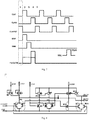
- GOA circuit 10 GOA unit 12, pull-up holding unit 121, pull-down unit 122, pull-up controlling unit 123, pull-up unit 124, bootstrap capacitor C, first transistor M1, second transistor M2, third transistor M3, fourth transistor M4, fifth transistor M5, sixth transistor M6, seventh transistor M7, eighth transistor M8, ninth transistor M9, tenth transistor M10, eleventh transistor M11, twelfth transistor M12, thirteenth transistor M13, fourteenth transistor M14, first enable input terminal ENA, second enable input terminal ENB, first clock signal terminal CLK, second clock signal terminal CLKB, first output terminal OUTA, second output terminal OUTB, reset terminal CLKRST, first clock signal CK1, second clock signal CK2, third clock signal CK3, fourth clock signal CK4, first starting signal STV1, second starting signal STV2, low level terminal VGL, first node PU, second node PD1, third node PD;
- the terms “mounted”, “connected”, “coupled” and the like are used broadly, and may be, for example, fixed connections, detachable connections, or integral connections; may also be mechanical or electrical connections; may also be direct connections or indirect connections via intervening structures; may also be inner communications of two elements, which can be understood by those skilled in the art according to specific situations.
- a structure in which a first feature is "on" or “below” a second feature may include an embodiment in which the first feature is in direct contact with the second feature, and may also include an embodiment in which the first feature and the second feature are not in direct contact with each other, but are contacted via an additional feature formed there between.
- a first feature "on”, “above” or “on top of a second feature may include an embodiment in which the first feature is right or obliquely “on”, “above” or “on top of the second feature, or just means that the first feature is at a height higher than that of the second feature; while a first feature "below”, “under” or “on bottom of a second feature may include an embodiment in which the first feature is right or obliquely “below”, “under” or “on bottom of the second feature, or just means that the first feature is at a height lower than that of the second feature.
- references numerals may be repeated in different examples in the present disclosure. This repeating is for the purpose of simplification and clarity and does not refer to relations between different embodiments and/or settings.
- examples of different processes and materials are provided in the present disclosure. However, it would be appreciated by those skilled in the art that other processes and/or materials may be also applied.
- Transistors used in all embodiments of the present disclosure may be a field effect transistor, and more specifically may be a thin film transistor (TFT). Since a source and a drain of the transistor used herein are symmetrical, they may be used interchangeably. In order to distinguish the two poles other than the gate of the field effect transistor, it may be determined that an upper end of the field effect transistor is defined as the source, a middle end is defined as the gate, and a lower end is defined as the drain as shown in the drawings.
- TFT thin film transistor
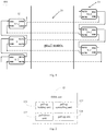
- a GOA circuit 10 is configured to provide a scanning pulse signal to a pixel matrix 20, and includes a plurality of GOA units 12 in cascade.
- the GOA unit 12 includes a first enable input terminal ENA, a second enable input terminal ENB, a first output terminal OUTA, a second output terminal OUTB and a first node PU.
- a first output terminal OUTA of a GOA unit 12 of a (N-2)th level is coupled to a first enable input terminal ENA of a GOA unit 12 of a Nth level
- a second output terminal OUTB of the GOA unit 12 of the (N-2)th level is coupled to a second enable input terminal ENB of a GOA unit 12 of a (N-1)th level, in which N is a natural number greater than 2.
- the second output terminal OUTB is configured to output the scanning pulse signal to the pixel matrix 20.
- the GOA unit 12 further includes a pull-up holding unit 121 configured to couple the second enable input terminal ENB to the first node PU and charge the first node PU to hold a voltage of the first node PU at a first preset voltage VGH.
- the GOA unit 12 of the (N-2)th level and the GOA unit 12 of the (N-1)th level may both charge the first node PU of the Nth level.
- the first node PU of the Nth level can still be charged, such that the GOA circuit 10 remains in a normal working state, and the reliability of the circuit is improved.
- the voltage of the first node PU will be further increased to (2VGH-VGL) during bootstrap output of the GOA unit 12, such that the second output terminal OUTB outputs the first preset voltage VGH, and thus may normally provide a scanning pulse signal to the pixel matrix 20, in which, VGL is the second preset voltage.
- the first preset voltage VGH may be a high level voltage
- the second preset voltage VGL may be a low level voltage.
- the array substrate 100 of the present disclosure includes a pixel matrix 20 and a GOA circuit 10.
- the array substrate 100 may be used for the display device 1000 of the present disclosure.
- the display device may be an electronic display device such as LCD and an AMOLED.
- the pixel matrix 20 includes a plurality of rows of pixels (not shown).
- a second output terminal OUTB of a GOA unit 12 of the current level is configured to output the scanning pulse signal to a corresponding row of pixels (not shown) in the pixel matrix 20, and the corresponding row of pixels (not shown) are coupled to a second enable input terminal ENB of a GOA unit 12 of a subsequent level.
- the GOA units 12 of two adjacent levels are disposed at two sides of the pixel matrix 20, respectively.
- the pull-up holding unit 121 includes a fourth transistor M4.
- a gate and a source of the fourth transistor M4 are coupled to the second enable input terminal ENB, and a drain of the fourth transistor M4 is coupled to the first node PU.
- the fourth transistor M4 may be able to boost the voltage of the first node PU back to the first preset voltage VGH in the subsequent holding stage.
- the GOA unit 12 includes a pull-down unit 122, a pull-up controlling unit 123, a bootstrap capacitor C, a pull-up unit 124, a second node PD1 and a third node PD, a first clock signal terminal CLK, a second clock signal terminal CLKB, a reset terminal CLKRST and a low level terminal VGL.
- the pull-down unit 122 is coupled to the first node PU, the second clock signal terminal CLKB and the low level terminal VGL.
- the pull-down unit 122 is configured to discharge the first node PU to clamp the voltage of the first node Pu at a second preset voltage VGL smaller than the first present voltage VGH.
- the pull-up controlling unit 123 is coupled to the first enable input terminal ENA and the first node PU and is configured to charge the first node PU to increase the voltage of the first node PU to the first preset voltage VGH.
- One terminal of the bootstrap capacitor C is coupled to the first node PU and the other terminal of the bootstrap capacitor C is coupled to the first output terminal OUTA.
- the pull-up unit 124 is coupled to the first clock signal terminal CLK, the second clock signal terminal CLKB, the first node PU, the low level terminal VGL, the first output terminal OUTA and the second output terminal OUTB, and is configured to discharge the second node PD1 and the third node PD to turn off the pull-down unit 122.
- the bootstrap capacitor C is configured to increase the voltage of the first node PU for a second time.
- the pull-down unit 122 includes a second transistor M2, a tenth transistor M10, an eleventh transistor M11, a twelfth transistor M12, a fourteenth transistor M14.
- a gate of the second transistor M2 is coupled to the reset terminal CLKRST, a source of the second transistor M2 is coupled to the first node PU, and a drain of the second transistor M2 is coupled to the low level terminal VGL.
- a gate of the tenth transistor M10 is coupled to the third node PD, a source of the tenth transistor M10 is coupled to the first node PU, and a drain of the tenth transistor M10 is coupled to the low level terminal VGL.
- a gate of the eleventh transistor M11 is coupled to the third node PD, a source of the eleventh transistor M11 is coupled to the second output terminal OUTB, and a drain of the eleventh transistor M11 is coupled to the low level terminal VGL.
- a gate of the twelfth transistor M12 is coupled to the reset terminal CLKRST, a source of the twelfth transistor M12 is coupled to the second output terminal OUTB, and a drain of the twelfth transistor M12 is coupled to the low level terminal VGL.
- a gate of the fourteenth transistor M14 is coupled to the third node PD, a source of the fourteenth transistor M14 is coupled to the first output terminal OUTA, and a drain of the fourteenth transistor M14 is coupled to the low level terminal VGL.
- the pull-down unit 122 may be configured to discharge the residual charges on the first node PU and a node of the second output terminal OUTB, and clamp voltages of the two nodes at the second preset voltage VGL.
- the pull-up controlling unit 123 includes a first transistor M1, a gate and a source of the first transistor M1 are coupled to the first enable input terminal ENA, and a drain of the first transistor M1 is coupled to the first node PU.
- the pull-up unit 124 includes a third transistor M3, a fifth transistor M5, a sixth transistor M6, a seventh transistor M7, an eighth transistor M8, a ninth transistor M9 and a thirteenth transistor M13.
- a gate of the third transistor M3 is coupled to the first node PU, a source of the third transistor M3 is coupled to the second clock signal terminal CLKB, and a drain of the third transistor M3 is coupled to the first output terminal OUTA.
- a gate of the fifth transistor M5 is coupled to the second node PD1, a source of the fifth transistor M5 is coupled to the second clock signal terminal CLKB, and a drain of the fifth transistor M5 is coupled to the third node PD.
- a gate of the sixth transistor M6 is coupled to the first node PU, a source of the sixth transistor M6 is coupled to the third node PD, and a drain of the sixth transistor M6 is coupled to the low level terminal VGL.
- a gate of the seventh transistor M7 is coupled to the first clock signal terminal CLK, a source of the seventh transistor M7 is coupled to the third node PD, and a drain of the seventh transistor M7 is coupled to the low level terminal VGL.
- a gate of the eighth transistor M8 is coupled to the first clock signal terminal CLK, a source of the eighth transistor M8 is coupled to the second node PD1, and a drain of the eighth transistor M8 is coupled to the low level terminal VGL.
- a gate and a source of the ninth transistor M9 are coupled to the second clock signal terminal CLKB, and a drain of the ninth transistor M9 is coupled to the second node PD1.
- a gate of the thirteenth transistor M13 is coupled to the first node Pu, a source of the thirteenth transistor M13 is coupled to the second clock signal terminal CLKB, and a drain of the thirteenth transistor M13 is coupled to the second output terminal OUTB.
- a first enable input terminal ENA of a GOA unit 12 of a first level is configured to receive a first starting signal STV1.
- a first enable input terminal ENA of a GOA unit 12 of a second level is configured to receive a second starting signal STV2.
- the first starting signal STV1 is configured to activate the GOA unit 12 of the first level
- the second starting signal STV2 is configured to activate the GOA unit 12 of the second level.
- a phase difference between the first clock signal terminal CLK and the second clock signal terminal CLKB is half of a cycle.
- a first clock signal terminal CLK of the GOA unit 12 of the (N-2)th level and a second clock signal terminal CLKB of the GOA unit 12 of the Nth level are configured to receive the first clock signal CK1
- a second clock signal terminal CLKB of the GOA unit 12 of the (N-2)th level and a first clock signal terminal CLK of the GOA unit 12 of the Nth level are configured to receive a third clock signal CK3
- a first clock signal terminal CLK of the GOA unit 12 of the (N-1)th level and a second clock signal terminal CLKB of a GOA unit 12 of a (N+1)th level are configured to receive a second clock signal CK2
- a second clock signal terminal CLKB of the GOA unit 12 of the (N-1)th level and the first clock signal terminal CLK of the GOA unit 12 of the (N+1)th level are configured to receive a fourth clock signal CK4.
- the reset terminal CLKRST of the GOA unit 12 of the (N-2)th level is configured to receive the fourth clock signal CK4, the reset terminal CLKRST of the GOA unit 12 of the (N-1)th level is configured to receive the first clock signal CK1, the reset terminal CLKRST of the GOA unit 12 of the Nth level is configured to receive the second clock signal CK2, and the reset terminal CLKRST of the GOA unit 12 of the (N+1)th level is configured to receive the third clock signal CK3.
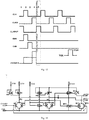
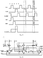
- the first clock signal CK1, the second clock signal CK2, the third clock signal CK3 and the fourth clock signal CK4 each have a duty cycle less than or equal to 25%.
- the first clock signal CK1, the second clock signal CK2, the third clock signal CK3 and the fourth clock signal CK4 each have a duty cycle less than or equal to 25%.
- the first clock signal CK1, the second clock signal CK2, the third clock signal CK3 and the fourth clock signal CK4 each output high level signal in turn.
- the fourth clock signal CK4 is configured to trigger the reset terminal CLKRST of the GOA unit 12 of the first level, and thus the fourth clock signal CK4 may first output a high level signal to complete the reset or initialization operation of the GOA unit 12 of the first level.
- the first starting signal STV1 and the second starting signal STV2 sequentially output a high level signal after the fourth clock signal CK4 to activate the GOA unit 12 of the first level and the GOA unit 12 of the second level.
- the desired output voltages of the second output terminals OUTBs of the GOA units 12 of the first level, the second level, and the third level as shown in Fig. 6 may be acquired.
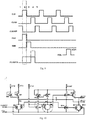
- the pull-up transistor includes the first transistor M1, the third transistor M3, the fourth transistor M4, the fifth transistor M5, the sixth transistor M6, the seventh transistor M7, the eighth transistor M8, the ninth transistor M9 and the thirteenth Transistor M13.
- the second transistor M2, the tenth transistor M10, the eleventh transistor M11, the twelfth transistor M12 and the fourteenth transistor M14 are turned on to discharge the residual charges on the first node PU and the node of the second output terminal OUTB and to clamp the voltages of the first node PU and the node of the second output terminal OUTB at the second preset voltage VGL.
- Second stage a pre-charging stage
- the signal from the first enable input terminal ENA of the (N-2)th level rises, and the first node PU is pre-charged by the first transistor M1 to the first preset voltage VGH. Voltages of the first clock signal terminal CLK and the first node PU rise simultaneously.
- the sixth transistor M6, the seventh transistor M7 and the eighth transistor M8 are turned on to discharge the second node PD1 and the third node PD.
- the voltage of the third node PD is decreased, and the tenth transistor M10, the eleventh transistor M11 and the fourteenth transistor M14 are turned off.
- the signal of the reset terminal CLKRST falls, and the second transistor M2 and the twelfth transistor M12 are turned off.
- the signal from the first enable input terminal ENA of the (N-2)th level falls, and the first transistor M1 is turned off.
- the signal from the second enable input terminal ENB of the (N-1)th level rises, and the fourth transistor M4 is turned on.
- the fourth transistor M4 subsequently charges the first node PU and holds the voltage of the first node PU at the first preset voltage VGH.
- the signal of the first clock signal terminal CLK falls, and the seventh transistor M7 and the eighth transistor M8 are turned off.
- the fourth transistor M4 may be able to boost the voltage of the first node PU back in the holding stage, thus effectively reducing the risk caused by electric leakage.
- a pulse of the second clock signal terminal CLKB occurs, and nodes of the first output terminal OUTA and the second output terminal OUTB are charged via the third transistor M3 and the thirteenth transistor M13 that have already been turned on.
- the voltage of the node of the first output terminal OUTA rises, and the gate voltage of the third transistor M3 may be further increased by the bootstrap capacitor C. In this way, More current may flow through the third transistor M3, resulting in a further increase in the voltage at the node of the first output terminal OUTA.
- Such an increase process continues until the voltage of the node of the first output terminal OUTA reaches the first preset voltage VGH. At this time, the voltage of the first node PU will reach (2VGH-VGL), thus ensuring that the gate voltage of the third transistor M3 is greater than the threshold voltage.
- the fifth transistor M5 and the ninth transistor M9 may charge the third node PD to try to increase the voltage of the third node PD.
- the ninth transistor M9 due to a delay of the ninth transistor M9, the fifth transistor M5 may have a lag opening.
- the first node PU has already been in a region of the first preset voltage VGH, such that the sixth transistor M6 may be turned on before the fifth transistor M5.
- the voltage of the third node PD will be maintained at the second preset voltage VGL by the wider, stronger sixth transistor M6. Therefore, the tenth transistor M10, the eleventh transistor M11 and the fourteenth transistor M14 remain turned off, and the above bootstrap output process will not be affected.
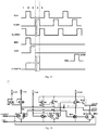
- the second transistor M2 and the twelfth transistor M12 are turned on by a pulse of the reset terminal CLKRST.
- the two transistors effectively discharge the first node PU and the node of the second output terminal OUTB, and thus the voltages of the first node PU and the node of the second output terminal OUTB are decreased to the second preset voltage VGL.
- the voltage of the node of the first output terminal OUTA may be decreased with the decrease of the voltage of the first node PU since the voltage difference across the bootstrap capacitor C is not enough to be stepped.
- the voltage of the node PU is decreased from (2VGH-VGL) to VGL
- the voltage of the node of the first output terminal OUTA has a tendency to fall below the second preset voltage VGL.
- the fourteenth transistor M14 is turned on to charge the node of the first output terminal OUTA. Therefore, the voltage of the node of the first output terminal OUTA is between VGL and (VGL-Vth), in which Vth is the threshold voltage.
- the seventh transistor M7 and the eighth transistor M8 are turned on, and the voltages of the second node PD1 and the third node PD are discharged to the second preset voltage VGL.
- the tenth transistor M10, the eleventh transistor M11 and the fourteenth transistor M14 are turned off.
- the first sixth stage is performed after the fifth stage, the other sixth stages are performed after the eighth stage.
- the tenth transistor M10, the eleventh transistor M11 and the fourteenth transistor M14 are turned on.
- the eighth stage the three transistors are kept on. Therefore, when the eighth stage ends and the sixth stage starts, the above three transistors are turned on.
- the fifth transistor M5 and the ninth transistor M9 charge the second node PD1 and the third node PD at the first preset voltage VGH.
- the tenth transistor M10, the eleventh transistor M11 and the fourteenth transistor M14 are turned on by the third node PD.
- the voltages of the first node PU, the node of the first output terminal OUTA and the node of the second output terminal OUTB are clamped to the second preset voltage VGL by the tenth transistor M10, the fourteenth transistor M14 and the eleventh transistor M11, respectively.
- the second transistor M2 and the twelfth transistor M12 are turned on.
- the voltage of the third node PD is maintained at the first preset voltage VGH, and the tenth transistor M10, the fourteenth transistor M14, and the eleventh transistor M11 continue to be turned on.
- the voltages of the first node PU, the node of the first output terminal OUTA, and the node of the second output terminal OUTB are clamped at the second preset voltage VGL.
- the sixth stage, the seventh stage and the eight stage are repeated in cycle.
- the voltages of the first node PU, the node of the first output terminal OUTA and the node of the second output terminal OUTB are clamped at the second preset voltage VGL.
- It may be returned to the first stage once a next frame of the scanning signal is output.
- changes in the GOA circuit 10 according to the embodiments of the present disclosure only relate to an addition of one transistor (i.e., the fourth transistor M4) and a few wiring changes, thus having a small circuit area.
Landscapes
- Engineering & Computer Science (AREA)
- Physics & Mathematics (AREA)
- General Physics & Mathematics (AREA)
- Computer Hardware Design (AREA)
- Theoretical Computer Science (AREA)
- Crystallography & Structural Chemistry (AREA)
- Chemical & Material Sciences (AREA)
- Nonlinear Science (AREA)
- Mathematical Physics (AREA)
- Optics & Photonics (AREA)
- Control Of Indicators Other Than Cathode Ray Tubes (AREA)
- Liquid Crystal Display Device Control (AREA)
- Shift Register Type Memory (AREA)
- Control Of El Displays (AREA)
Claims (10)
- Circuit GOA de commande de porte sur réseau (10), configuré pour fournir un signal d'impulsion de balayage à une matrice de pixels (20), comprenant une pluralité d'unités GOA (12) en cascade, dans lequel l'unité GOA (12) comprend une première borne d'entrée de validation (ENA), une seconde borne d'entrée de validation (ENB), une première borne de sortie (OUTA), une seconde borne de sortie (OUTB) et un premier noeud (PU),une première borne de sortie (OUTA) d'une unité GOA (12) d'un (N-2)ème niveau est couplée à une première borne d'entrée de validation (ENA) d'une unité GOA (12) d'un Nème niveau, une seconde borne de sortie (OUTB) de l'unité GOA (12) du (N-2)ème niveau est couplée à une seconde borne d'entrée de validation (ENB) d'une unité GOA (12) d'un (N-1)ème niveau, dans lequel N est un nombre naturel supérieur à 2, la seconde borne de sortie (OUTB) est configurée pour délivrer le signal d'impulsion de balayage à une rangée correspondante de pixels dans la matrice de pixels (20);et l'unité GOA (12) comprend en outre une unité de maintien d'excursion haute (121), l'unité de maintien d'excursion haute (121) étant configurée pour coupler la seconde borne d'entrée de validation (ENB) au premier noeud (PU) et charger le premier noeud (PU) pour maintenir une tension du premier noeud (PU) à une première tension prédéfinie;dans lequel l'unité de maintien d'excursion haute (121) comprend un quatrième transistor (M4), une grille et une source du quatrième transistor (M4) sont couplées à la deuxième borne d'entrée de validation (ENB), et un drain du quatrième transistor (M4) est couplé au premier noeud (PU);caractérisé en ce que l'unité GOA (12) comprend en outre une unité de tirage vers le bas (122), une unité de commande de tirage vers le haut (123), un condensateur d'amorçage (C), une unité de tirage vers le haut (124), un deuxième noeud (PD1) et un troisième noeud (PD), une première borne de signal d'horloge (CLK), une deuxième borne de signal d'horloge (CLKB), une borne de réinitialisation (CLKRST) et une borne de niveau bas (VGL),dans lequel l'unité de commande d'excursion basse (122) est couplée au premier noeud (PU), à la borne de réinitialisation (CLKRST) et à la borne de niveau bas (VGL), et configurée pour décharger le premier noeud (PU) afin de bloquer la tension du premier noeud (PU) à une seconde tension prédéfinie inférieure à la première tension actuelle ; l'unité de commande d'excursion haute (123) est couplée à la première borne d'entrée de validation (ENA) et au premier noeud (PU), et configurée pour charger le premier noeud (PU) afin d'augmenter la tension du premier noeud (PU) à la première tension prédéfinie ; une borne du condensateur d'amorçage (C) est couplée au premier noeud (PU) et l'autre borne du condensateur d'amorçage (C) est couplée à la première borne de sortie (OUTA) ; et l'unité d'excursion haute (124) est couplée à la première borne de signal d'horloge (CLK), à la deuxième borne de signal d'horloge (CLKB), au premier noeud (PU), à la borne de niveau bas (VGL), à la première borne de sortie (OUTA) et à la deuxième borne de sortie (OUTB), et configurée pour décharger le deuxième noeud (PD1) et le troisième noeud (PD) pour désactiver l'unité d'excursion basse (122);dans lequel l'unité de commande d'excursion haute (123) comprend un premier transistor (M1), une grille et une source du premier transistor (M1) sont couplées à la première borne d'entrée de validation (ENA), et un drain du premier transistor (M1) est couplé au premier noeud (PU);dans lequel l'unité d'excursion haute (124) comprend un troisième transistor (M3), un cinquième transistor (M5), un sixième transistor (M6), un septième transistor (M7), un huitième transistor (M8), un neuvième transistor (M9) et un treizième transistor (M13), dans lequel une grille du troisième transistor (M3) est couplée au premier noeud (PU), une source du troisième transistor (M3) est couplée à la deuxième borne de signal d'horloge (CLKB), et un drain du troisième transistor (M3) est couplé à la première borne de sortie (OUTA);une grille du cinquième transistor (M5) est couplée au deuxième noeud (PD1), une source du cinquième transistor (M5) est couplée à la deuxième borne de signal d'horloge (CLKB), et un drain du cinquième transistor (M5) est couplé au troisième noeud (PD);une grille du sixième transistor (M6) est couplée au premier noeud (PU), une source du sixième transistor (M6) est couplée au troisième noeud (PD), et un drain du sixième transistor (M6) est couplé à la borne de niveau bas (VGL);une grille du septième transistor (M7) est couplée à la première borne de signal d'horloge (CLK), une source du septième transistor (M7) est couplée au troisième noeud (PD) et un drain du septième transistor (M6) est couplé à la borne de niveau bas (VGL) ; et une grille du huitième transistor (M7) est couplée à la borne de niveau bas (VGL);une grille du huitième transistor (M8) est couplée à la première borne de signal d'horloge (CLK), une source du huitième transistor (M8) est couplée au deuxième noeud (PD1), et un drain du huitième transistor (M8) est couplé à la borne de niveau bas (VGL);une grille et une source du neuvième transistor (M9) sont couplées à la deuxième borne de signal d'horloge (CLKB), et un drain du neuvième transistor (M9) est couplé au deuxième noeud (PD1);et une grille du treizième transistor (M13) est couplée au premier noeud (PU), une source du treizième transistor (M13) est couplée à la deuxième borne de signal d'horloge (CLKB), et un drain du treizième transistor (M13) est couplé à la deuxième borne de sortie (OUTB).
- Circuit GOA(10) selon la revendication 1, dans lequel la matrice de pixels (20) comprend une pluralité de rangées de pixels, et une seconde borne de sortie (OUTB) d'une unité GOA(12) d'un niveau courant est configurée pour sortir le signal d'impulsion de balayage vers une rangée correspondante de pixels dans la matrice de pixels (20), et la rangée correspondante de pixels est couplée à une seconde borne d'entrée de validation (ENB) d'une unité GOA(12) d'un niveau suivant.
- Le circuit GOA(10) selon la revendication 1 ou 2, dans lequel les unités GOA (12) de deux niveaux adjacents sont disposées sur deux côtés de la matrice de pixels (20), respectivement.
- Circuit GOA(10) selon l'une quelconque des revendications 1 à 3, dans lequel l'unité de tirage vers le bas (122) comprend un deuxième transistor (M2), un dixième transistor (M10), un onzième transistor (M11), un douzième transistor (M12), un quatorzième transistor (M14), dans lequel une grille du deuxième transistor (M2) est couplée à la borne de réinitialisation (CLKRST), une source du deuxième transistor (M2) est couplée au premier noeud (PU), et un drain du deuxième transistor (M2) est couplé à la borne de niveau bas (VGL);une grille du dixième transistor (M10) est couplée au troisième noeud (PD), une source du dixième transistor (M10) est couplée au premier noeud (PU), et un drain du dixième transistor (M10) est couplé à la borne de niveau bas (VGL);une grille du onzième transistor (M11) est couplée au troisième noeud (PD), une source du onzième transistor (M11) est couplée à la deuxième borne de sortie (OUTB), et un drain du onzième transistor (M11) est couplé à la borne de niveau bas (VGL);une grille du douzième transistor (M12) est couplée à la borne de réinitialisation (CLKRST), une source du douzième transistor (M12) est couplée à la deuxième borne de sortie (OUTB), et un drain du douzième transistor (M12) est couplé à la borne de niveau bas (VGL);et une grille du quatorzième transistor (M14) est couplée au troisième noeud (PD), une source du quatorzième transistor (M14) est couplée à la première borne de sortie (OUTA), et un drain du quatorzième transistor (M14) est couplé à la borne de niveau bas (VGL).
- Circuit GOA(10) selon l'une quelconque des revendications 1 à 4, dans lequel une première borne d'entrée de validation (ENA) d'une unité GOA (12) d'un premier niveau est configurée pour recevoir un premier signal de démarrage (STV1), et une première borne d'entrée de validation (ENA) d'une unité GOA (12) d'un second niveau est configurée pour recevoir un second signal de démarrage (STV2), le premier signal de démarrage (STV1) est configuré pour activer l'unité GOA (12) du premier niveau, et le deuxième signal de démarrage (STV2) est configuré pour activer l'unité GOA (12) du deuxième niveau.
- Le circuit GOA(10) selon l'une quelconque des revendications 1 à 4, dans lequel une différence de phase entre la première borne de signal d'horloge (CLK) et la seconde borne de signal d'horloge (CLKB) est la moitié d'un cycle.
- Le circuit GOA(10) selon l'une quelconque des revendications 1 à 4, dans lequel une première borne de signal d'horloge (CLK) de l'unité GOA (12) du (N-2)ème niveau et une seconde borne de signal d'horloge (CLKB) de l'unité GOA (12) du Nème niveau sont configurées pour recevoir le premier signal d'horloge (CK1), une deuxième borne de signal d'horloge (CLKB) de l'unité GOA (12) du (N-2)ème niveau et une première borne de signal d'horloge (CLK) de l'unité GOA (12) du Nème niveau sont configurées pour recevoir le premier signal d'horloge (CK1), et un troisième signal d'horloge (CK3), une première borne de signal d'horloge (CLK) de l'unité GOA (12) du (N-1)ème niveau et une deuxième borne de signal d'horloge (CLKB) d'une unité GOA(12) d'un (N+1)ème niveau sont configurées pour recevoir un deuxième signal d'horloge (CK2), une deuxième borne de signal d'horloge (CLKB) de l'unité GOA (12) du (N-1)ème niveau et une première borne de signal d'horloge (CLK) de l'unité GOA (12) du (N+1)ème niveau sont configurées pour recevoir un quatrième signal d'horloge (CK4).
- Circuit GOA(10) selon la revendication 7, dans lequel le premier signal d'horloge (CK1), le deuxième signal d'horloge (CK2), le troisième signal d'horloge (CK3) et le quatrième signal d'horloge (CK4) ont chacun un rapport cyclique inférieur ou égal à 25%.
- Substrat de réseau (100), caractérisé en ce qu'il comprend :une matrice de pixels (20) ; etun circuit GOA(10) selon l'une quelconque des revendications 1 à 8.
- Dispositif d'affichage (1000) caractérisé en ce qu'il comprend un substrat de matrice (100) selon la revendication 9.
Applications Claiming Priority (1)
| Application Number | Priority Date | Filing Date | Title |
|---|---|---|---|
| PCT/CN2016/110146 WO2018107440A1 (fr) | 2016-12-15 | 2016-12-15 | Circuit de commande de grille sur réseau (goa), substrat de réseau et dispositif d'affichage |
Publications (3)
| Publication Number | Publication Date |
|---|---|
| EP3557581A1 EP3557581A1 (fr) | 2019-10-23 |
| EP3557581A4 EP3557581A4 (fr) | 2020-07-22 |
| EP3557581B1 true EP3557581B1 (fr) | 2021-12-08 |
Family
ID=62004250
Family Applications (1)
| Application Number | Title | Priority Date | Filing Date |
|---|---|---|---|
| EP16924147.8A Not-in-force EP3557581B1 (fr) | 2016-12-15 | 2016-12-15 | Circuit de commande de grille sur réseau (goa), substrat de réseau et dispositif d'affichage |
Country Status (6)
| Country | Link |
|---|---|
| US (1) | US10733949B2 (fr) |
| EP (1) | EP3557581B1 (fr) |
| JP (1) | JP2019533201A (fr) |
| KR (1) | KR102243866B1 (fr) |
| CN (1) | CN107980160B (fr) |
| WO (1) | WO2018107440A1 (fr) |
Families Citing this family (7)
| Publication number | Priority date | Publication date | Assignee | Title |
|---|---|---|---|---|
| US20210280108A1 (en) * | 2017-05-15 | 2021-09-09 | Shenzhen Royole Technologies Co., Ltd. | Goa circuit, array substrate, and display device |
| CN109036303A (zh) * | 2018-07-24 | 2018-12-18 | 武汉华星光电技术有限公司 | Goa电路及显示装置 |
| WO2020062027A1 (fr) * | 2018-09-28 | 2020-04-02 | 深圳市柔宇科技有限公司 | Unité de pilotage de balayage, circuit de pilotage de balayage, substrat matriciel et dispositif d'affichage |
| KR102498797B1 (ko) * | 2018-09-28 | 2023-02-10 | 삼성디스플레이 주식회사 | 유기 발광 표시 장치 |
| WO2021051270A1 (fr) * | 2019-09-17 | 2021-03-25 | Boe Technology Group Co., Ltd. | Circuit d'unité goa, procédé d'attaque, circuit goa et appareil d'affichage |
| CN112967646B (zh) * | 2020-11-11 | 2022-12-16 | 重庆康佳光电技术研究院有限公司 | 低电平有效的goa单元和显示屏 |
| US11362594B1 (en) * | 2021-09-09 | 2022-06-14 | Crane Electronics, Inc. | Radiation tolerant gate drive scheme for active-clamp reset forward topology with active-driven synchronous rectification |
Family Cites Families (20)
| Publication number | Priority date | Publication date | Assignee | Title |
|---|---|---|---|---|
| KR100860239B1 (ko) * | 2002-04-08 | 2008-09-25 | 삼성전자주식회사 | 액정표시장치 |
| KR101192777B1 (ko) * | 2005-12-02 | 2012-10-18 | 엘지디스플레이 주식회사 | 쉬프트 레지스터 |
| KR20070076293A (ko) * | 2006-01-18 | 2007-07-24 | 삼성전자주식회사 | 액정 표시 장치 및 그의 복구 방법 |
| KR101281498B1 (ko) * | 2006-10-31 | 2013-07-02 | 삼성디스플레이 주식회사 | 게이트 구동회로 및 이를 갖는 표시장치 |
| KR101573460B1 (ko) * | 2009-04-30 | 2015-12-02 | 삼성디스플레이 주식회사 | 게이트 구동회로 |
| KR101373979B1 (ko) * | 2010-05-07 | 2014-03-14 | 엘지디스플레이 주식회사 | 게이트 쉬프트 레지스터와 이를 이용한 표시장치 |
| CN101937718B (zh) | 2010-08-04 | 2013-02-13 | 友达光电股份有限公司 | 双向移位寄存器 |
| KR101889951B1 (ko) * | 2011-12-23 | 2018-08-21 | 엘지디스플레이 주식회사 | 유기발광 표시장치의 발광제어신호 발생 장치 |
| CN103050106B (zh) * | 2012-12-26 | 2015-02-11 | 京东方科技集团股份有限公司 | 栅极驱动电路、显示模组和显示器 |
| CN203217931U (zh) * | 2013-03-25 | 2013-09-25 | 北京京东方光电科技有限公司 | 一种移位寄存器、栅极驱动电路以及显示装置 |
| CN103426414B (zh) * | 2013-07-16 | 2015-12-09 | 北京京东方光电科技有限公司 | 移位寄存器单元及其驱动方法、栅极驱动电路及显示装置 |
| KR102077786B1 (ko) * | 2013-08-12 | 2020-02-17 | 삼성디스플레이 주식회사 | 스테이지 회로 및 이를 이용한 주사 구동부 |
| CN103680386B (zh) * | 2013-12-18 | 2016-03-09 | 深圳市华星光电技术有限公司 | 用于平板显示的goa电路及显示装置 |
| CN103943058B (zh) * | 2014-04-28 | 2017-04-05 | 华南理工大学 | 一种行栅极扫描器及其驱动方法 |
| CN104505046B (zh) * | 2014-12-29 | 2017-04-19 | 上海天马微电子有限公司 | 一种栅极驱动电路、阵列基板、显示面板和显示装置 |
| KR102281237B1 (ko) * | 2015-02-13 | 2021-07-26 | 삼성디스플레이 주식회사 | 게이트 회로, 게이트 회로의 구동방법 및 이를 이용한 표시장치 |
| CN104766586B (zh) | 2015-04-29 | 2017-08-29 | 合肥京东方光电科技有限公司 | 移位寄存器单元、其驱动方法、栅极驱动电路及显示装置 |
| CN104978943B (zh) * | 2015-08-06 | 2017-03-08 | 京东方科技集团股份有限公司 | 一种移位寄存器、显示面板的驱动方法及相关装置 |
| CN105336300B (zh) * | 2015-12-04 | 2019-03-26 | 昆山龙腾光电有限公司 | 移位寄存器、栅极驱动电路及显示装置 |
| CN106128409B (zh) * | 2016-09-21 | 2018-11-27 | 深圳市华星光电技术有限公司 | 扫描驱动电路及显示装置 |
-
2016
- 2016-12-15 CN CN201680039408.7A patent/CN107980160B/zh not_active Expired - Fee Related
- 2016-12-15 JP JP2019521397A patent/JP2019533201A/ja active Pending
- 2016-12-15 US US16/334,971 patent/US10733949B2/en not_active Expired - Fee Related
- 2016-12-15 KR KR1020197019470A patent/KR102243866B1/ko not_active Expired - Fee Related
- 2016-12-15 WO PCT/CN2016/110146 patent/WO2018107440A1/fr not_active Ceased
- 2016-12-15 EP EP16924147.8A patent/EP3557581B1/fr not_active Not-in-force
Also Published As
| Publication number | Publication date |
|---|---|
| US10733949B2 (en) | 2020-08-04 |
| WO2018107440A1 (fr) | 2018-06-21 |
| KR102243866B1 (ko) | 2021-04-22 |
| EP3557581A4 (fr) | 2020-07-22 |
| CN107980160A (zh) | 2018-05-01 |
| WO2018107440A9 (fr) | 2018-11-08 |
| EP3557581A1 (fr) | 2019-10-23 |
| US20200020292A1 (en) | 2020-01-16 |
| JP2019533201A (ja) | 2019-11-14 |
| KR20190090850A (ko) | 2019-08-02 |
| CN107980160B (zh) | 2020-08-28 |
Similar Documents
| Publication | Publication Date | Title |
|---|---|---|
| EP3557581B1 (fr) | Circuit de commande de grille sur réseau (goa), substrat de réseau et dispositif d'affichage | |
| JP7315469B2 (ja) | シフトレジスタユニットおよびその駆動方法、ゲート駆動回路および表示装置 | |
| US8493309B2 (en) | Shift register circuit and image display comprising the same | |
| US10540923B2 (en) | Shift register, method for driving same, gate driving circuit | |
| US8615066B2 (en) | Shift register circuit | |
| US10217428B2 (en) | Output control unit for shift register, shift register and driving method thereof, and gate driving device | |
| CN105185339B (zh) | 移位寄存器单元、栅线驱动装置以及驱动方法 | |
| US9501989B2 (en) | Gate driver for narrow bezel LCD | |
| CN102708926B (zh) | 一种移位寄存器单元、移位寄存器、显示装置和驱动方法 | |
| US10037741B2 (en) | Shift register unit and driving method thereof, as well as array substrate gate drive device and display panel | |
| CN106297615B (zh) | 显示装置的检测电路及方法 | |
| WO2017117895A1 (fr) | Registre à décalage, procédé de pilotage et circuit de pilotage d'électrode de grille | |
| US11450294B2 (en) | Shift register, gate driving circuit and driving method for the same, and liquid crystal display | |
| US20210183326A1 (en) | Shift register element, method for driving the same, gate driver circuit, and display device | |
| CN105810170A (zh) | 移位寄存器单元及其驱动方法、栅线驱动电路和阵列基板 | |
| CN204966019U (zh) | 移位寄存器单元和栅线驱动装置 | |
| US11527215B2 (en) | Display device having gate driving circuit | |
| JP7506750B2 (ja) | ゲート駆動回路及び駆動方法 | |
| US9905181B2 (en) | Array substrate and scan driving circuit thereon | |
| WO2018209519A1 (fr) | Circuit goa, substrat de réseau, et dispositif d'affichage | |
| US20160379585A1 (en) | Gate driver on array circuit, driving method thereof, and display device including the same | |
| CN106601172B (zh) | 移位寄存器单元、驱动方法、栅极驱动电路和显示装置 | |
| CN117198192A (zh) | 驱动电路、驱动模组和显示装置 | |
| US12347355B2 (en) | Gate driving circuit and display panel |
Legal Events
| Date | Code | Title | Description |
|---|---|---|---|
| STAA | Information on the status of an ep patent application or granted ep patent |
Free format text: STATUS: THE INTERNATIONAL PUBLICATION HAS BEEN MADE |
|
| PUAI | Public reference made under article 153(3) epc to a published international application that has entered the european phase |
Free format text: ORIGINAL CODE: 0009012 |
|
| STAA | Information on the status of an ep patent application or granted ep patent |
Free format text: STATUS: REQUEST FOR EXAMINATION WAS MADE |
|
| 17P | Request for examination filed |
Effective date: 20190315 |
|
| AK | Designated contracting states |
Kind code of ref document: A1 Designated state(s): AL AT BE BG CH CY CZ DE DK EE ES FI FR GB GR HR HU IE IS IT LI LT LU LV MC MK MT NL NO PL PT RO RS SE SI SK SM TR |
|
| AX | Request for extension of the european patent |
Extension state: BA ME |
|
| DAV | Request for validation of the european patent (deleted) | ||
| DAX | Request for extension of the european patent (deleted) | ||
| A4 | Supplementary search report drawn up and despatched |
Effective date: 20200618 |
|
| RIC1 | Information provided on ipc code assigned before grant |
Ipc: G09G 3/3266 20160101ALI20200612BHEP Ipc: G09G 3/36 20060101ALI20200612BHEP Ipc: G09G 3/20 20060101ALI20200612BHEP Ipc: G11C 19/28 20060101AFI20200612BHEP |
|
| STAA | Information on the status of an ep patent application or granted ep patent |
Free format text: STATUS: EXAMINATION IS IN PROGRESS |
|
| 17Q | First examination report despatched |
Effective date: 20210222 |
|
| GRAP | Despatch of communication of intention to grant a patent |
Free format text: ORIGINAL CODE: EPIDOSNIGR1 |
|
| STAA | Information on the status of an ep patent application or granted ep patent |
Free format text: STATUS: GRANT OF PATENT IS INTENDED |
|
| INTG | Intention to grant announced |
Effective date: 20210705 |
|
| GRAS | Grant fee paid |
Free format text: ORIGINAL CODE: EPIDOSNIGR3 |
|
| GRAA | (expected) grant |
Free format text: ORIGINAL CODE: 0009210 |
|
| STAA | Information on the status of an ep patent application or granted ep patent |
Free format text: STATUS: THE PATENT HAS BEEN GRANTED |
|
| AK | Designated contracting states |
Kind code of ref document: B1 Designated state(s): AL AT BE BG CH CY CZ DE DK EE ES FI FR GB GR HR HU IE IS IT LI LT LU LV MC MK MT NL NO PL PT RO RS SE SI SK SM TR |
|
| REG | Reference to a national code |
Ref country code: GB Ref legal event code: FG4D |
|
| REG | Reference to a national code |
Ref country code: AT Ref legal event code: REF Ref document number: 1454385 Country of ref document: AT Kind code of ref document: T Effective date: 20211215 Ref country code: CH Ref legal event code: EP |
|
| REG | Reference to a national code |
Ref country code: DE Ref legal event code: R096 Ref document number: 602016067279 Country of ref document: DE |
|
| REG | Reference to a national code |
Ref country code: IE Ref legal event code: FG4D |
|
| REG | Reference to a national code |
Ref country code: LT Ref legal event code: MG9D |
|
| REG | Reference to a national code |
Ref country code: NL Ref legal event code: MP Effective date: 20211208 |
|
| PG25 | Lapsed in a contracting state [announced via postgrant information from national office to epo] |
Ref country code: RS Free format text: LAPSE BECAUSE OF FAILURE TO SUBMIT A TRANSLATION OF THE DESCRIPTION OR TO PAY THE FEE WITHIN THE PRESCRIBED TIME-LIMIT Effective date: 20211208 Ref country code: LT Free format text: LAPSE BECAUSE OF FAILURE TO SUBMIT A TRANSLATION OF THE DESCRIPTION OR TO PAY THE FEE WITHIN THE PRESCRIBED TIME-LIMIT Effective date: 20211208 Ref country code: FI Free format text: LAPSE BECAUSE OF FAILURE TO SUBMIT A TRANSLATION OF THE DESCRIPTION OR TO PAY THE FEE WITHIN THE PRESCRIBED TIME-LIMIT Effective date: 20211208 Ref country code: BG Free format text: LAPSE BECAUSE OF FAILURE TO SUBMIT A TRANSLATION OF THE DESCRIPTION OR TO PAY THE FEE WITHIN THE PRESCRIBED TIME-LIMIT Effective date: 20220308 |
|
| PGFP | Annual fee paid to national office [announced via postgrant information from national office to epo] |
Ref country code: GB Payment date: 20220120 Year of fee payment: 6 |
|
| REG | Reference to a national code |
Ref country code: AT Ref legal event code: MK05 Ref document number: 1454385 Country of ref document: AT Kind code of ref document: T Effective date: 20211208 |
|
| PG25 | Lapsed in a contracting state [announced via postgrant information from national office to epo] |
Ref country code: SE Free format text: LAPSE BECAUSE OF FAILURE TO SUBMIT A TRANSLATION OF THE DESCRIPTION OR TO PAY THE FEE WITHIN THE PRESCRIBED TIME-LIMIT Effective date: 20211208 Ref country code: NO Free format text: LAPSE BECAUSE OF FAILURE TO SUBMIT A TRANSLATION OF THE DESCRIPTION OR TO PAY THE FEE WITHIN THE PRESCRIBED TIME-LIMIT Effective date: 20220308 Ref country code: LV Free format text: LAPSE BECAUSE OF FAILURE TO SUBMIT A TRANSLATION OF THE DESCRIPTION OR TO PAY THE FEE WITHIN THE PRESCRIBED TIME-LIMIT Effective date: 20211208 Ref country code: HR Free format text: LAPSE BECAUSE OF FAILURE TO SUBMIT A TRANSLATION OF THE DESCRIPTION OR TO PAY THE FEE WITHIN THE PRESCRIBED TIME-LIMIT Effective date: 20211208 Ref country code: GR Free format text: LAPSE BECAUSE OF FAILURE TO SUBMIT A TRANSLATION OF THE DESCRIPTION OR TO PAY THE FEE WITHIN THE PRESCRIBED TIME-LIMIT Effective date: 20220309 Ref country code: ES Free format text: LAPSE BECAUSE OF FAILURE TO SUBMIT A TRANSLATION OF THE DESCRIPTION OR TO PAY THE FEE WITHIN THE PRESCRIBED TIME-LIMIT Effective date: 20211208 |
|
| PG25 | Lapsed in a contracting state [announced via postgrant information from national office to epo] |
Ref country code: NL Free format text: LAPSE BECAUSE OF FAILURE TO SUBMIT A TRANSLATION OF THE DESCRIPTION OR TO PAY THE FEE WITHIN THE PRESCRIBED TIME-LIMIT Effective date: 20211208 |
|
| REG | Reference to a national code |
Ref country code: DE Ref legal event code: R119 Ref document number: 602016067279 Country of ref document: DE |
|
| PG25 | Lapsed in a contracting state [announced via postgrant information from national office to epo] |
Ref country code: SM Free format text: LAPSE BECAUSE OF FAILURE TO SUBMIT A TRANSLATION OF THE DESCRIPTION OR TO PAY THE FEE WITHIN THE PRESCRIBED TIME-LIMIT Effective date: 20211208 Ref country code: SK Free format text: LAPSE BECAUSE OF FAILURE TO SUBMIT A TRANSLATION OF THE DESCRIPTION OR TO PAY THE FEE WITHIN THE PRESCRIBED TIME-LIMIT Effective date: 20211208 Ref country code: RO Free format text: LAPSE BECAUSE OF FAILURE TO SUBMIT A TRANSLATION OF THE DESCRIPTION OR TO PAY THE FEE WITHIN THE PRESCRIBED TIME-LIMIT Effective date: 20211208 Ref country code: PT Free format text: LAPSE BECAUSE OF FAILURE TO SUBMIT A TRANSLATION OF THE DESCRIPTION OR TO PAY THE FEE WITHIN THE PRESCRIBED TIME-LIMIT Effective date: 20220408 Ref country code: EE Free format text: LAPSE BECAUSE OF FAILURE TO SUBMIT A TRANSLATION OF THE DESCRIPTION OR TO PAY THE FEE WITHIN THE PRESCRIBED TIME-LIMIT Effective date: 20211208 Ref country code: CZ Free format text: LAPSE BECAUSE OF FAILURE TO SUBMIT A TRANSLATION OF THE DESCRIPTION OR TO PAY THE FEE WITHIN THE PRESCRIBED TIME-LIMIT Effective date: 20211208 |
|
| REG | Reference to a national code |
Ref country code: CH Ref legal event code: PL |
|
| PG25 | Lapsed in a contracting state [announced via postgrant information from national office to epo] |
Ref country code: PL Free format text: LAPSE BECAUSE OF FAILURE TO SUBMIT A TRANSLATION OF THE DESCRIPTION OR TO PAY THE FEE WITHIN THE PRESCRIBED TIME-LIMIT Effective date: 20211208 Ref country code: AT Free format text: LAPSE BECAUSE OF FAILURE TO SUBMIT A TRANSLATION OF THE DESCRIPTION OR TO PAY THE FEE WITHIN THE PRESCRIBED TIME-LIMIT Effective date: 20211208 |
|
| REG | Reference to a national code |
Ref country code: BE Ref legal event code: MM Effective date: 20211231 |
|
| PG25 | Lapsed in a contracting state [announced via postgrant information from national office to epo] |
Ref country code: MC Free format text: LAPSE BECAUSE OF FAILURE TO SUBMIT A TRANSLATION OF THE DESCRIPTION OR TO PAY THE FEE WITHIN THE PRESCRIBED TIME-LIMIT Effective date: 20211208 Ref country code: IS Free format text: LAPSE BECAUSE OF FAILURE TO SUBMIT A TRANSLATION OF THE DESCRIPTION OR TO PAY THE FEE WITHIN THE PRESCRIBED TIME-LIMIT Effective date: 20220408 |
|
| PLBE | No opposition filed within time limit |
Free format text: ORIGINAL CODE: 0009261 |
|
| STAA | Information on the status of an ep patent application or granted ep patent |
Free format text: STATUS: NO OPPOSITION FILED WITHIN TIME LIMIT |
|
| PG25 | Lapsed in a contracting state [announced via postgrant information from national office to epo] |
Ref country code: LU Free format text: LAPSE BECAUSE OF NON-PAYMENT OF DUE FEES Effective date: 20211215 Ref country code: IE Free format text: LAPSE BECAUSE OF NON-PAYMENT OF DUE FEES Effective date: 20211215 Ref country code: DK Free format text: LAPSE BECAUSE OF FAILURE TO SUBMIT A TRANSLATION OF THE DESCRIPTION OR TO PAY THE FEE WITHIN THE PRESCRIBED TIME-LIMIT Effective date: 20211208 Ref country code: DE Free format text: LAPSE BECAUSE OF NON-PAYMENT OF DUE FEES Effective date: 20220701 Ref country code: AL Free format text: LAPSE BECAUSE OF FAILURE TO SUBMIT A TRANSLATION OF THE DESCRIPTION OR TO PAY THE FEE WITHIN THE PRESCRIBED TIME-LIMIT Effective date: 20211208 |
|
| 26N | No opposition filed |
Effective date: 20220909 |
|
| PG25 | Lapsed in a contracting state [announced via postgrant information from national office to epo] |
Ref country code: SI Free format text: LAPSE BECAUSE OF FAILURE TO SUBMIT A TRANSLATION OF THE DESCRIPTION OR TO PAY THE FEE WITHIN THE PRESCRIBED TIME-LIMIT Effective date: 20211208 Ref country code: BE Free format text: LAPSE BECAUSE OF NON-PAYMENT OF DUE FEES Effective date: 20211231 |
|
| PG25 | Lapsed in a contracting state [announced via postgrant information from national office to epo] |
Ref country code: LI Free format text: LAPSE BECAUSE OF NON-PAYMENT OF DUE FEES Effective date: 20211231 Ref country code: FR Free format text: LAPSE BECAUSE OF NON-PAYMENT OF DUE FEES Effective date: 20220208 Ref country code: CH Free format text: LAPSE BECAUSE OF NON-PAYMENT OF DUE FEES Effective date: 20211231 |
|
| PG25 | Lapsed in a contracting state [announced via postgrant information from national office to epo] |
Ref country code: IT Free format text: LAPSE BECAUSE OF FAILURE TO SUBMIT A TRANSLATION OF THE DESCRIPTION OR TO PAY THE FEE WITHIN THE PRESCRIBED TIME-LIMIT Effective date: 20211208 |
|
| PG25 | Lapsed in a contracting state [announced via postgrant information from national office to epo] |
Ref country code: CY Free format text: LAPSE BECAUSE OF FAILURE TO SUBMIT A TRANSLATION OF THE DESCRIPTION OR TO PAY THE FEE WITHIN THE PRESCRIBED TIME-LIMIT Effective date: 20211208 |
|
| PG25 | Lapsed in a contracting state [announced via postgrant information from national office to epo] |
Ref country code: HU Free format text: LAPSE BECAUSE OF FAILURE TO SUBMIT A TRANSLATION OF THE DESCRIPTION OR TO PAY THE FEE WITHIN THE PRESCRIBED TIME-LIMIT; INVALID AB INITIO Effective date: 20161215 |
|
| GBPC | Gb: european patent ceased through non-payment of renewal fee |
Effective date: 20221215 |
|
| PG25 | Lapsed in a contracting state [announced via postgrant information from national office to epo] |
Ref country code: GB Free format text: LAPSE BECAUSE OF NON-PAYMENT OF DUE FEES Effective date: 20221215 |
|
| PG25 | Lapsed in a contracting state [announced via postgrant information from national office to epo] |
Ref country code: MK Free format text: LAPSE BECAUSE OF FAILURE TO SUBMIT A TRANSLATION OF THE DESCRIPTION OR TO PAY THE FEE WITHIN THE PRESCRIBED TIME-LIMIT Effective date: 20211208 |
|
| PG25 | Lapsed in a contracting state [announced via postgrant information from national office to epo] |
Ref country code: MT Free format text: LAPSE BECAUSE OF FAILURE TO SUBMIT A TRANSLATION OF THE DESCRIPTION OR TO PAY THE FEE WITHIN THE PRESCRIBED TIME-LIMIT Effective date: 20211208 |
|
| PG25 | Lapsed in a contracting state [announced via postgrant information from national office to epo] |
Ref country code: TR Free format text: LAPSE BECAUSE OF FAILURE TO SUBMIT A TRANSLATION OF THE DESCRIPTION OR TO PAY THE FEE WITHIN THE PRESCRIBED TIME-LIMIT Effective date: 20211208 |