EP3557094B1 - Maillon de fermeture à chaînes - Google Patents
Maillon de fermeture à chaînes Download PDFInfo
- Publication number
- EP3557094B1 EP3557094B1 EP19000236.0A EP19000236A EP3557094B1 EP 3557094 B1 EP3557094 B1 EP 3557094B1 EP 19000236 A EP19000236 A EP 19000236A EP 3557094 B1 EP3557094 B1 EP 3557094B1
- Authority
- EP
- European Patent Office
- Prior art keywords
- chain
- region
- diameter
- bolt
- pin
- Prior art date
- Legal status (The legal status is an assumption and is not a legal conclusion. Google has not performed a legal analysis and makes no representation as to the accuracy of the status listed.)
- Active
Links
Images


Classifications
-
- F—MECHANICAL ENGINEERING; LIGHTING; HEATING; WEAPONS; BLASTING
- F16—ENGINEERING ELEMENTS AND UNITS; GENERAL MEASURES FOR PRODUCING AND MAINTAINING EFFECTIVE FUNCTIONING OF MACHINES OR INSTALLATIONS; THERMAL INSULATION IN GENERAL
- F16G—BELTS, CABLES, OR ROPES, PREDOMINANTLY USED FOR DRIVING PURPOSES; CHAINS; FITTINGS PREDOMINANTLY USED THEREFOR
- F16G15/00—Chain couplings, Shackles; Chain joints; Chain links; Chain bushes
- F16G15/04—Quickly-detachable chain couplings; Shackles chain links with rapid junction means are classified according to the corresponding kind of chain
-
- F—MECHANICAL ENGINEERING; LIGHTING; HEATING; WEAPONS; BLASTING
- F16—ENGINEERING ELEMENTS AND UNITS; GENERAL MEASURES FOR PRODUCING AND MAINTAINING EFFECTIVE FUNCTIONING OF MACHINES OR INSTALLATIONS; THERMAL INSULATION IN GENERAL
- F16G—BELTS, CABLES, OR ROPES, PREDOMINANTLY USED FOR DRIVING PURPOSES; CHAINS; FITTINGS PREDOMINANTLY USED THEREFOR
- F16G15/00—Chain couplings, Shackles; Chain joints; Chain links; Chain bushes
-
- F—MECHANICAL ENGINEERING; LIGHTING; HEATING; WEAPONS; BLASTING
- F16—ENGINEERING ELEMENTS AND UNITS; GENERAL MEASURES FOR PRODUCING AND MAINTAINING EFFECTIVE FUNCTIONING OF MACHINES OR INSTALLATIONS; THERMAL INSULATION IN GENERAL
- F16G—BELTS, CABLES, OR ROPES, PREDOMINANTLY USED FOR DRIVING PURPOSES; CHAINS; FITTINGS PREDOMINANTLY USED THEREFOR
- F16G13/00—Chains
- F16G13/02—Driving-chains
- F16G13/06—Driving-chains with links connected by parallel driving-pins with or without rollers so called open links
-
- F—MECHANICAL ENGINEERING; LIGHTING; HEATING; WEAPONS; BLASTING
- F16—ENGINEERING ELEMENTS AND UNITS; GENERAL MEASURES FOR PRODUCING AND MAINTAINING EFFECTIVE FUNCTIONING OF MACHINES OR INSTALLATIONS; THERMAL INSULATION IN GENERAL
- F16G—BELTS, CABLES, OR ROPES, PREDOMINANTLY USED FOR DRIVING PURPOSES; CHAINS; FITTINGS PREDOMINANTLY USED THEREFOR
- F16G15/00—Chain couplings, Shackles; Chain joints; Chain links; Chain bushes
- F16G15/12—Chain links
- F16G15/14—Chain links made of sheet metal, e.g. profiled
-
- B—PERFORMING OPERATIONS; TRANSPORTING
- B62—LAND VEHICLES FOR TRAVELLING OTHERWISE THAN ON RAILS
- B62K—CYCLES; CYCLE FRAMES; CYCLE STEERING DEVICES; RIDER-OPERATED TERMINAL CONTROLS SPECIALLY ADAPTED FOR CYCLES; CYCLE AXLE SUSPENSIONS; CYCLE SIDE-CARS, FORECARS, OR THE LIKE
- B62K3/00—Bicycles
Definitions
- the present invention relates to a chain connecting link for a drive chain which cooperates with a multiple pinion with a large number of gears on a bicycle rear wheel.
- Drive chains for bicycles with derailleur gears are made up of chain links that are pivotably arranged with respect to one another, with the aid of which a closed chain loop is formed for the transmission of drive force.
- These chain links can be rotated relative to one another about chain pins, the chain pins being received by perforations which are located in the two end regions of each link plate.
- the two end areas of each link plate are connected to one another by a connection area with an outer contour that is mostly tapered.
- the chain links consist of either a pair of inner plates or a pair of outer plates.
- the outer link and inner link pairs are connected to one another in an alternating manner by means of the chain pins. Because of this arrangement, the distance between an outer plate pair is slightly larger than that between an inner plate pair.
- the ends of the chain loop are connected to one another by means of a chain connecting link.
- the closure member can either be resealable or can only be used once.
- the closure member is formed by a pair of outer plate, which, however, differs from the usual pairs of outer plates in some features.
- the transition from the small end diameter to the narrow point in the assembly opening allows the chain pin to move in the opening direction without jamming.
- this jam-free area creates a slight play between the pin and the small end diameter, which in turn can lead to unintentional dismantling under heavy load on the chain.
- the task arises of providing a chain connecting link which prevents unintentional dismantling of the chain connecting link even under heavy loads, for example in the case of strong vibrations or impacts in uneven terrain.
- the present invention solves this problem with a chain locking link according to the main claim, consisting of two locking parts, each with a locking plate and a chain pin connected non-rotatably to the locking plate.
- the closure plate has a first end area, a second end area and a connecting area between the two end areas. Furthermore, an elongated hole, comprising an insertion opening, a holding opening and a displacement area lying between the insertion opening and the holding opening, is arranged in the first end area of the closure plate. The displacement area narrows from the insertion opening towards the holding opening and forms a throat constriction.
- the chain pin has a pin head with a pin neck at one end and a pin base at the other end.
- a diameter D21 of the insertion opening is larger than a diameter D41 of the bolt head 41.
- a diameter D22 of the holding opening is smaller than the diameter D41 of the bolt head and larger than, or at least as large as a diameter D42 of the bolt neck.
- the neck constriction is dimensioned smaller than the diameter D42 of the bolt neck. Between the throat constriction and the holding opening of the elongated hole there is a clamping area which is smaller than the diameter D42 of the bolt neck.
- the clamping area represents a further dismantling safeguard.
- the holding opening described an arc of a circle up to the narrow point with a diameter that was dimensioned somewhat larger than the diameter of the bolt neck.
- the clamping area according to the invention is now arranged between the circular arc of the holding opening and the constriction and allows the bolt to be clamped against the edge of the holding opening or the edge of the depression without play.
- the clamping takes place in the radial direction on the bolt, that is, transversely to the longitudinal axis of the bolt B.
- the clamping area is arranged in the lower half of the displacement area.
- the closure plate is designed asymmetrically along its longitudinal axis V and the connecting area of the closure plate has a concave edge area and a non-concave edge area, the non-concave edge area being designed as a straight edge area.
- a positive effect of this asymmetrical design is that the cross-sectional area of the closure plate increases.
- the cross-sectional area corresponds to the area that becomes visible when the closure plate is cut centrally along its transverse axis (perpendicular to its longitudinal axis V).
- Conventional locking plates of chain locking links usually have, just like the other outer and inner plates, a symmetrical and thus concave connection area on both sides (compare illustration of the prior art).
- the cross section of a closure plate that is concave on both sides thus has a smaller area than a closure plate with a less concave or non-concave edge region.
- the less concave the edge area the larger the cross-sectional area.
- a straight edge area has a larger cross section than a concave but less than a convex.
- the straight edge area represents a good compromise between stability and unwinding ability of the closure link.
- the stability and the breaking resistance of the closure plate are increased due to the enlarged cross-sectional area of the closure plate compared to a concave edge area; Version with convex edge area.
- the clamping area is formed by two opposing clamping slopes.
- the two clamping slopes are non-parallel to one another. Rather, the two clamping bevels run away from one another in the direction of the holding opening (that is, in the assembly direction), so that their distance from one another increases. This has the effect that the bolt is pushed in the direction of the retaining opening.
- the distance between the two clamping bevels is dimensioned such that the distance is even smaller at the widest point A2 than the diameter D42 of the bolt neck.
- the clamping area or the clamping bevels are arranged in the lower half of the displacement area. The clamping area or the clamping bevels interact with the bolt neck.
- clamping area or the opposing clamping bevels in the upper half of the displacement area.
- the clamping area would then interact with the bolt head.
- the distance between the clamping bevels would then be dimensioned so that it is also at the furthest point would be even smaller than the diameter of the bolt head.
- the bolt head In its end position, the bolt head would rest on both clamping bevels and on the edge of the depression. In this way, the bolt would also be held or clamped in its end position without play in the closure plate.
- the elongated hole has a ramp in its displacement area.
- the bolt head slides with its underside during the assembly of the chain locking link along the ramp, the ramp rising along the displacement area in the direction of the holding opening.
- the ramp represents an additional dismantling protection.
- the bolt head must overcome the slope of the ramp and thus its clamping effect in the axial direction of the bolt before it reaches its end position.
- the displacement area of the elongated hole narrows from the insertion opening towards the holding opening at a further point, so that a head constriction is also formed in addition to the neck constriction.
- the head constriction is dimensioned smaller than the diameter of the bolt head.
- the additional head constriction represents a further dismantling protection for the locking link.
- an elongated hole longitudinal axis L of the elongated hole runs obliquely to the closure plate longitudinal axis V.
- the elongated hole longitudinal axis L extends in an angular range of 5 degrees to 25 degrees, preferably 15 degrees, to the closure plate longitudinal axis V.
- This inclined position of the elongated hole with respect to the longitudinal axis V of the closure plate ensures that there is enough material around the elongated hole, that is, there is sufficient distance from the edges of the closure plate. This maintains the stability of the closure plate.
- connection area of the closure plate has a recess.
- the recess allows a particularly narrow chain design because the locking plates can be brought very close together and still enough space remains for the teeth to engage.
- the recess can be produced by embossing or milling.
- the outside of the closure plate preferably remains flat. This prevents the outside of the closure plate from inadvertently colliding with teeth or other components when changing from one gear wheel to the next.
- closure plate This is a particularly thin embodiment of the closure plate, which calls for an enlarged cross-sectional area and thus a non-concave edge area all the more.
- embossing presses material onto the outside, which leads to a non-flat outside.
- the recess viewed in the direction of the longitudinal axis of the closure plate, is dimensioned smaller in the area of the straight edge area than in the area of the concave edge area. This has the effect that the cross-sectional area of the closure plate is increased further due to the reduced recess, which in turn increases the stability of the closure plate.
- the contours of the recess which run symmetrically relative to the transverse axis of the closure plate, have a curved, tapering course from the concave edge region towards the centrally located closure plate longitudinal axis. From the longitudinal axis of the closure plate to the straight edge area, the contours run essentially in a straight line, that is, parallel to the transverse axis of the closure plate. Thus, viewed in the direction of the longitudinal axis of the closure plate, the recess is dimensioned smaller in the area of the straight edge area and in the area near the longitudinal axis of the closure plate than in the area of the concave edge area.
- a further object of the invention is thus to provide a closure member that allows both a narrow design with little spacing between the closure plates and a secure engagement of the teeth between the closure plates, and also offers sufficient stability and dismantling security.
- Curved or banana-shaped closure members are already known from the prior art, for example from US Pat U.S. 7,712,298 and the U.S. 7,914,410 .
- the disadvantage of these curved closure members is that they do not allow a narrow construction.
- Another disadvantage of the known closure members from the prior art is that there is insufficient security against dismantling under heavy loads. Both documents only disclose a dismantling lock in the form of a constriction formed by two projections in the displacement area of the elongated hole, which cooperates with the bolt neck. During assembly, the bolt neck snaps behind this projection.
- the present invention solves this problem with a chain locking link according to the independent claim, consisting of two locking parts, each with a locking plate and a chain bolt connected to the locking plate in a rotationally fixed manner, the locking plate having a first end area, a second end area and a connecting area between the two end areas and the connection area of the closure plate has a concave edge area and a non-concave edge area.
- an elongated hole comprising an insertion opening, a holding opening and a displacement area lying between the introduction opening and the holding opening is arranged in the first end area of the closure plate, the displacement area extending from the insertion opening narrows towards the retaining opening and forms a head constriction and / or neck constriction and wherein the chain pin has a bolt head with a bolt neck at one end and a bolt foot at the other end, a diameter D21 of the insertion opening being greater than a Diameter D41 of the bolt head, and a diameter D22 of the retaining opening is smaller than the diameter D41 of the bolt head and greater than a diameter D42 of the bolt neck.
- the head constriction is dimensioned smaller than the diameter D41 of the bolt head and / or the neck constriction is dimensioned smaller than the diameter D42 of the bolt neck, the connecting area of the closure plate having a recess and the non-concave edge area in particular being straight Edge area is formed.
- the recess in the connection area leads to a lowering in relation to the first and second end areas of the closure plate.
- the lowering creates enough space, even with a narrow chain design, to allow the teeth of the chainrings or sprockets to engage. This is particularly necessary for drives with only one chainring and an increased number of around 12 sprockets. In particular, such drives often have alternating thick and thin teeth on the front sprocket and / or the rear pinions. In this case, the recess creates enough space so that such a thick tooth can also engage in the intermediate space of the closure member.
- the straight edge area represents a good compromise between stability and rollability of the closure member.
- the stability and the breaking resistance of the closure plate increase due to the enlarged cross-sectional area of the closure plate compared to a concave edge area; on the other hand, the rolling behavior of the locking link on the upper chain guide roller improves compared to the version with a convex edge area.
- the recess viewed in the direction of the longitudinal axis of the closure plate, is dimensioned smaller in the area of the straight edge area than in the area of the concave edge area. This has the effect that the cross-sectional area of the closure plate is increased further due to the reduced recess, which in turn increases the stability of the closure plate.
- the contours of the recess which run symmetrically relative to the transverse axis of the closure plate, have a curved, tapering course from the concave edge region towards the centrally located closure plate longitudinal axis. From the longitudinal axis of the closure plate to the straight edge area, the contours run essentially in a straight line, that is, parallel to the transverse axis of the closure plate. Thus, viewed in the direction of the longitudinal axis of the closure plate, the recess is dimensioned smaller in the area of the straight edge area and in the area near the longitudinal axis of the closure plate than in the area of the concave edge area.
- the dismantling safeguard in the form of a head constriction and / or neck constriction ensures increased dismantling safety.
- a clamping area is arranged between the head constriction and the holding opening of the elongated hole, which is dimensioned smaller than the diameter D41 of the bolt head.
- a further clamping area is arranged between the neck constriction and the holding opening of the elongated hole, which is dimensioned smaller than the diameter D42 of the bolt neck.
- the clamping area represents a further dismantling safeguard. It also has the effect that the bolt, when it has overcome the constriction in the displacement area of the elongated hole, is held in the holding opening in a clamping and play-free manner by means of the clamping area.
- the clamping area can be arranged at the level of the bolt neck (in the lower half of the displacement area) and / or the bolt head (in the upper half of the displacement area).
- up and “down” relate, among other things, to the direction of the bolt longitudinal axis B, the bolt head 41 being arranged further up than the bolt neck 42 and the bolt base 43 being arranged further down than the bolt neck 42.
- inside and “outside” refer to the sides of the locking plates.
- the inner surfaces of the closure plates face each other in the mounted state of the closure member.
- the outer surfaces of the closure plates face away from one another in the assembled state of the closure member. The terms are used equally in connection with the bolts and the locking plates.
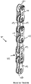
- FIG Figure 1 a section of a bicycle chain 1 known from the prior art with a conventional locking link 5.
- the chain 1 consists of alternating pairs of outer link plates 2 and inner link plates 3.
- the link plate pairs are connected in an articulated manner by means of chain rivets 4.
- a chain roller 6 is assigned to each chain rivet 4.
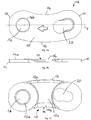
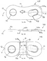
- Figure 1a and Figure 1b show the chain closure link 5 according to the invention in the non-assembled state.
- the two identical locking parts each consisting of a locking plate 10 and a chain pin 40, are rotated 180 degrees to one another and aligned for assembly.
- the Figure 1a shows a perspective view of the chain locking link 5.
- the insides of the two locking plates 10 face each other.
- the closure plates 10 each have a first end area 11 with an elongated hole 20 and a second end area 12 with a bolt hole 16.
- the arrow embossed in the connection area 15 located between the two end areas 11, 12 of the closure plate 10 shows the direction of chain travel and thus the mounting orientation of the closure link 10.
- the bolts 40 are each preassembled, in particular riveted, with their one end, the bolt foot 43, in a rotationally fixed manner in the bolt bore 16. At the other end of the The bolt head 41 rests on the bolt 40.
- Figure 1b shows a side view of the chain locking link 5 from FIG Figure 1a .
- the bolt 40 extends along its bolt longitudinal axis B.
- the bolt 40 tapers on the bolt neck 42 compared to the bolt body and bolt head 41.
- the bolt head 41 has a diameter D41 which is smaller than the diameter D21, the insertion opening 21 of the Long hole 20.
- the bolt head 41 of the one closure part can be inserted into the insertion opening 21 of the elongated hole 20 of the other closure part in each case.
- Figure 2 shows the first assembly step of the closure member.
- the smaller-diameter bolt 40 of the one closure part is inserted into the larger-diameter insertion opening 21 of the other closure part in each case.
- the bolt 40 is positioned in the direction of the bolt longitudinal axis B in such a way that the bolt head 41 protrudes slightly beyond the outer surface of the closure plate 10.
- the two locking parts are inserted into one another without any effort.
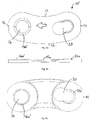
- FIG 3 shows the subsequent second assembly step, in which the two locking parts are shifted against each other.
- the bolts 40 each move along the elongated hole 20 from the insertion opening 21 to the holding opening 22.
- the sliding movement takes place mainly in the direction of the longitudinal axis of the closure plates V, the bolt 40 only moves slightly in the direction of its longitudinal axis B.
- the bolt 40 passes a displacement area of the elongated hole 20.
- several bottlenecks are arranged which the bolt 40 has to overcome.
- the displacement movement of the bolt 40 can only take place under the action of force.
- the bolt 40 snaps or engages, so to speak, in the holding opening 22.
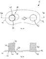
- FIGs 4a to 4d show the third assembly step and thus also the end position of the two locking parts.
- both bolts 40 are shown, only one closure plate 10 of the closure member 5 is shown.
- FIG 4a a top view of the fully assembled closure member 5 is shown.
- the bolt head 41 is in its end position in the holding opening 22 of the elongated hole 20.
- FIG. 3 is the sectional view of FIG Figure 4a along section line 4b-4b. It can be clearly seen here that the bolt head 41, after it has overcome the ramp 30, is arranged so deep in the elongated hole 20 that it does not or barely protrudes in the axial direction B beyond the outside of the closure plate.
- FIG. 3 is a sectional view of FIG Figure 4c along the section line 4d-4d, which runs through the bolt neck 42 just below the bolt head 41.
- the clamping area 27, which holds the bolt 40 in the holding opening 22 without play, is indicated here.
- the diameter D42 of the bolt neck 42 is slightly larger than the distance between the opposing slopes of the clamping area 27.
- the clamping slopes engage the bolt neck 42 and press the bolt 40 against the edge of the holding opening 22 in the direction of the first end area 11.
- the bolt 40 rests in the end position both on the edge of the holding opening 22 and on the two clamping slopes of the clamping area 27.
- the at least three contact points ensure a backlash-free clamping of the bolt 40 in its end position.
- Figure 5a is a detailed view of the elongated hole 20 in plan view - that is, the outside of the closure plate 10.
- the elongated hole 20 consists of an insertion opening 21 with a larger diameter, a displacement area and a smaller-diameter holding opening 22.
- the displacement area which lies between the two openings 21, 22, narrows in the direction of the holding opening 22.
- the insertion opening 21 describes a circular section with a diameter D21, which is dimensioned somewhat larger than the bolt head 41.
- the holding opening 22 also describes a circular section with a diameter D22, which corresponds to the diameter D41 of the bolt neck 41 or is slightly larger.
- the clamping area 27 adjoins the holding opening 22.
- the clamping area 27 is formed by two opposing and non-parallel clamping bevels 27a, 27b.
- a circle drawn with a dashed line is indicated with a diameter which corresponds approximately to the holding opening 22 or the bolt neck 41. It can be seen that the Clamping bevels 27a, 27b are clearly within the indicated circle and the bolt will therefore not have enough space in its end position. The lack of space leads to a slight deformation of the bolt and the locking plate during assembly. This elastic deformation clamps the bolt along the bolt neck in the elongated hole 20.
- the distance between the opposing clamping slopes 27a, 27b increases in the direction of the holding opening 22 from a distance A1 to a distance A2.
- the distance A1 between the two clamping bevels 27a, 27b corresponds at the same time to the neck constriction 26 in the displacement range of the elongated hole 20.
- the bolt neck must overcome this neck constriction 26 under the action of force before it then moves along the clamping bevels 27a, 27b in the assembly direction into the end position is pressed.
- the distance A1 is dimensioned somewhat smaller than the diameter D42 of the bolt neck.
- the distance A2 corresponds approximately to the diameter D42 of the bolt neck.
- the distance A3 corresponds to the head constriction 24 and is smaller than the diameter of the bolt head.
- the bolt head must also overcome this under the action of force.
- Both the narrow point to be overcome at the level of the bolt neck and the narrow point at the level of the bolt head result in a radial clamping of the bolt along the neck or the head.
- the two bottlenecks are arranged one behind the other in the assembly direction and each represent a dismantling lock.
- the insertion opening has a diameter of 3.75 mm and the holding opening has a diameter of 3 mm.
- the displacement area tapers in the assembly direction by 0.75 mm.
- the bolt head has a diameter of 3.64 mm and can therefore be easily inserted into the insertion opening.
- the bolt neck has a diameter of 2.93 mm and there is sufficient space in the holding opening.
- the starting distance A1 between the clamping bevels is 2.82 mm and the end distance A2 is 2.93 mm, so that the bolt neck is securely held in its end position.
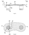
- Figure 6 shows a perspective sectional view of the closure plate 10 or the greatly enlarged elongated hole 20, on the basis of which the displacement of the bolt in the assembly direction can best be described.
- Figure 6 To the contour of the elongated hole 20 and to make the shifting area more visible in particular is shown in Figure 6 only one side of the elongated hole 20 is shown and the course of the bolt along this side of the elongated hole 20 shown is explained. Of course, the bolt moves along the other (not visible here) side of the elongated hole in the same way.
- the effect of the clamping bevels and constrictions can naturally only arise together with the side of the elongated hole, which is not shown here.
- the bolt head is first inserted into the insertion opening 21 of the elongated hole 20.
- the bolt head is then located in the upper half of the insertion opening 21 of the elongated hole 20 or a little above (cf. also Fig. 2 ).
- the “upper half” of the elongated hole is the area of the elongated hole that is closer to the outside of the closure plate 10.
- the outside of the closure plate 10 is shown in FIG Figure 6 up.
- the “lower half” of the elongated hole is correspondingly closer to the inside of the closure plate.
- the bolt head moves in the assembly direction due to the dimensions of the bolt and slot only in the upper half of the slot.
- the bolt neck moves accordingly in the lower half of the elongated hole.
- the lower half of the elongated hole only offers enough space for the bolt head in the area of the insertion opening 21, but not in the displacement area and in the area of the holding opening 22.
- the bolt is shifted in the assembly direction (along the elongated hole longitudinal axis L) in the direction of the holding opening 22 and passes through the displacement area between the insertion opening 21 and the holding opening 22 in several steps (see also FIG Fig. 3 ).
- the lateral edge of the bolt head slides under increasing force along the increasing head clamping slope 23a before it reaches the head constriction 24.
- the corresponding second head clamping slope (23b) is located on the opposite side of the elongated hole, which is not shown here.
- the head constriction 24 is formed by two opposing surfaces or edges in the upper half of the elongated hole 20.
- the distance A3 at the head constriction 24 is dimensioned smaller than the diameter D41 of the bolt head (cf. Figure 5b ). The bolt head can only overcome the head constriction 24 under the action of force.
- the underside of the bolt head slides over the ramp 30 before it rests in the bottom 31 of the countersink in its end position.
- the ramp 30 extends approximately perpendicular to the sides of the elongated hole 20.
- the bolt head after it has overcome the ramp 30, snaps in the direction of the bolt longitudinal axis B downwards onto the base 31 of the countersink.
- the ramp 30 first rises, then reaches a highest point and then falls again.
- the edge of the highest point of the ramp 30 is in Fig. 6 clearly visible.
- the level of the ramp 30 is so far above the base 31 of the countersink that this difference can only be overcome by means of increased force and the closure parts can be detached from one another.
- the bolt head rests against both the edge 29 and the base 31 of the depression.
- the edge of the holding opening 22 engages in the circumferential bolt groove or the bolt neck and the remainder of the bolt body extends below the closure plate 10 (cf. Fig. 4 ).
- the bolt is thus secured in the axial direction B.
- the ramp 30 is a further dismantling lock.
- the bolt neck moves along the lower half of the elongated hole 20.
- the bolt neck slides under increasing force along the rising neck clamping slope 25a before it reaches the neck constriction 26.
- the corresponding second neck clamping bevel 25b is located on the opposite side of the elongated hole 20, which is not shown here.
- the neck constriction 26 is formed by two opposing edges in the lower half of the elongated hole 20.
- the distance A1 at the neck constriction 26 is smaller than the diameter D42 of the bolt neck (cf. Figure 5b ). The bolt neck can only overcome the neck constriction 26 under the action of force.
- the clamping area 27 is formed by two opposing clamping slopes 27a, 27b.
- the two clamping bevels 27a, b do not run parallel to one another, but rather in the direction of the holding opening (i.e. in FIG Mounting direction) away from each other, so that their distance from each other increases. This has the effect that the bolt is pressed in the direction of the holding opening 22. In its end position, the bolt neck rests on both clamping bevels 27a, 27b and on the edge of the holding opening 22. In this way, the bolt is held or clamped in its end position without play in the closure plate 10.
- the clamping takes place in the radial direction of the bolt and represents a further dismantling protection.
- the two bottlenecks described above are at different heights. Furthermore, the constrictions are arranged one after the other in the assembly direction (from the insertion opening 21 in the direction of the holding opening 22). In the exemplary embodiment shown, the head constriction 24 lies in front of the neck constriction 26 in the assembly direction. That is, the bolt head must first pass the head constriction 24 before the bolt neck can pass the neck constriction 26.
- the bottlenecks could, however, also be arranged one above the other, so that they have to be overcome at the same time.
- the bolt After the bolt has overcome the two radial narrow points in the area of the bolt head and bolt neck and also the axial clamping effect of the ramp, it snaps into its end position and, due to the clamping area 27 according to the invention, lies against the closure plate 10 without play.
- the two bolts of the two locking parts overcome the respective dismantling locks at the same time, so that the locking parts are securely fixed in their end position without play.
- the assembly must accordingly take place under a relatively large force, which ideally can be defined and exerted in a controlled manner by means of an assembly tool.
- the various dismantling locks in the form of the narrow point at the level of the bolt neck and / or the narrow point at the level of the bolt head, the clamping surfaces at the level of the bolt neck and / or the clamping surfaces at the level of the bolt head (radial bolt clamping) and the ramp (axial bolt clamping) are separate from each other or can be used in combination with one another.
- FIG 7 shows a first embodiment of a closure plate 10 according to the invention
- Figure 7a the shape of the closure plate 10 can be clearly seen.
- the closure plate 10 is designed asymmetrically along its longitudinal axis V.
- the connecting region 15, which is arranged between the first end region 11 and the second end region 12, is not designed with a waist as in the prior art.
- the connection area 15 has a concave edge area 14 and a convex edge area 13.
- the elongated hole 20 and the bolt hole 16 with its countersink 16b can also be seen.
- the countersink 16b creates space for riveting the bolt base and takes up the deformed material of the bolt base.
- FIG. 7b The side view of the connecting plate 10 shown in the illustration clearly shows the recess 15a in the connecting area 15.
- the connection area 15 is clearly lowered compared to the two end areas 11, 12.
- the material thickness of the closure plate 10 in the region of the recess 15a is therefore less than in the end regions 11, 12.
- the recess 15a in the closure plate 10 facilitates the engagement of a tooth, even if the closure plates 10 are very close together in the assembled state.
- Figure 7a shows the inside of the closure plate 10.
- the recess 15a can also be clearly seen here.
- the recess 15a is delimited by the curved end regions 11, 12 and extends up to the edges 13 and 14. This results in a recess 15a which has a smaller width in the area of the longitudinal axis V of the closure plate than at the edge regions 13, 14.
- the transition between the recess 15a and the chamfers 13a and 14a is rounded. Between the depression 15a and the chamfers 13a, 14a there are preferably no edges but tangential transitions. The chamfers 13a and 14a along the edges further facilitate the penetration of the tooth.
- the pin bore 16 has a projection on the inside of the closure plate 10 16a on. This is created by the countersink 16b on the outside of the closure plate 10, because material is pressed through to the other side. The projection 16a increases the stability of the plate 10.
- the material thickness reduced due to the recess 15a and the associated reduced cross section of the closure plate 10 is compensated for by the changed outer contour of the closure plate 10.
- the convex edge 13 increases the cross section of the closure plate 10 and thus increases its stability.
- the closure plate 10 is produced from a flat starting material. The original material thickness is only found in the end areas 11, 12. In the connection area 15, something has been removed from the original material thickness, so that the recess 15a is created in particular by embossing.
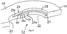
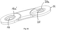
- Figure 8a-d shows a second embodiment of the closure plate 10 '.
- the enlarged countersink 16b ' can accommodate more deformed bolt material.
- the elongated hole 20 also has a projection 20a on the inside of the closure plate 10'.
- This projection 20a is also produced by material deformation of the plate 10 ′ and contributes to the stability in the area of the elongated hole 20.
- the projection 20a slopes down in the direction of the first end region 11 and can be seen particularly well in the side view and in perspective.
- Figure 9a 9b shows the outside and FIG. 9b the inside of a third embodiment of the closure plate 10 ′′.
- This closure plate 10 ′′ differs from the other two on account of its contour.
- one edge area 14 is concave and the other edge area 17 is straight.
- the concave edge area 14 follows the shape of the other outer and inner plates and the straight edge area 17 is a good compromise between stability and rolling behavior on the upper chain roller of the rear derailleur.
- the straight edge region 17 also has a bevel 17a, which enables a tooth to engage in the space between two opposing teeth Locking plates facilitated.
- the chamfers 13a, 14a, 17a in all embodiments form a kind of funnel shape with the largest possible clearance for the engaging teeth.
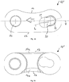
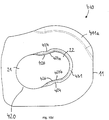
- Figure 10a shows a fourth embodiment of the closure plate 410 in plan view.
- the closure plate 410 likewise has a first and second end region 11, 12, a concave edge region 14 and a straight edge region 17 that runs essentially in a straight line.
- the bolt bore 16 and the elongated hole 420 largely correspond to the previous exemplary embodiments.
- the different dismantling locks of the fourth embodiment is referred to in connection with Figure 10d entered into more detail.
- the longitudinal axis V of the closure plate 410 runs through the center points of the bolt bore 16 and the holding opening 22.
- the straight edge region 17 extends parallel to the longitudinal axis V of the closure plate 410 Chamfer 411a arranged.
- the first bevel 411a improves the switching behavior of the chain.
- Figure 10b shows the fourth embodiment in a side view. Both the projection 16a on the bolt hole 16 and the projection 420a on the elongated hole 420 are visible here.
- the connecting area 415 or the recess 415a, which is lowered with respect to the end areas 11, 12, can also be seen.
- the additional material of the projections 16a and 420a leads to an increase in the cross section and thus to more stability and breaking resistance of the closure plate 410 in the area of the two openings 16, 420.
- Figure 10c shows the closure plate 410 in a view from below or the inside of the plate 410.
- the transverse axis Q of the closure plate 410 running perpendicular to the longitudinal axis V is also shown here.
- chamfers 417a and 14a are provided along the edge regions 17 and 14. They make it easier for a tooth to engage in the space between two opposing locking plates.
- the recess 415a is delimited on the one hand by the two end regions 11, 12 and, on the other hand, extends to the edge regions 14, 17.
- the course of the delimitations by the end regions 11, 12 or the first contour 418 differs the recess 415a and the second contour 419 of the recess 415a from the previous, continuously arcuate embodiments.
- the first contour 418 and the second contour 419 of the recess 415a run symmetrically with respect to the transverse axis Q.
- the contours 418, 419 of the recess 415a have a curved, tapering course from the concave edge region 14 towards the centrally located longitudinal axis V. They run essentially in a straight line from the longitudinal axis V to the straight edge region 17, i.e. parallel to the transverse axis Q.
- the recess 415a in the direction of the longitudinal axis V in the region of the straight edge region 17 is smaller than in the region of the concave edge region 14 the recess 415a is dimensioned smaller in the area near the longitudinal axis V than in the area near the concave edge area 14.
- the recess 415a is dimensioned approximately the same size in the area of the longitudinal axis V and in the area of the straight edge area 17. This has the advantage that more material at the edge region 17 leads to an increased cross-sectional area of the closure plate 410 and more stability. In comparison to this, the cross-sectional area of the previous exemplary embodiment is somewhat smaller due to the recess 15a (continuously arcuate contour of the recess) which increases in the direction of the concave edge region 14 and also in the direction of the straight edge region 17. The increased cross-section of the closure plate 410 due to the reduced recess 415a contributes to the somewhat reduced cross-section of a straight edge area 17 compared to a convex edge area 13 ( Figures 1a to 8 ) to compensate.
- the tooth engagement opening of the closure member is thus dimensioned larger at the concave edge areas 14 in the longitudinal direction of the closure plates 410 than on the side of the straight edge areas 17.
- the recess 15a on the non-concave edge 13, 17 is significantly larger than on the concave edge 14.
- the recess 415a, which is narrower at the edge regions 17, is nevertheless sufficiently large to ensure smooth operation.
- the bicycle chain 1 forms a closed chain loop, the links of which mesh with the teeth of the front chainring and the pinion and the lower and upper chain guide rollers of the rear derailleur run through in an S-shaped curve.
- the concave edge areas 14 of the locking link point in the direction of the teeth of the chainring, the pinion and also the lower chain guide roller.
- the upper chain guide roller Only when passing through the upper chain guide roller do the straight edge areas 17 and not the concave edge areas 14 point in the direction of the teeth of the upper chain guide roller.
- the upper chain guide roller usually has only one group of thin teeth, the axial width of which is matched to the tooth engagement openings of the inner plate pairs.
- the smaller-sized recess 415a of the locking link is therefore still sufficiently large in the area of the straight edge area 17 to be able to accommodate the teeth of the upper chain guide roller.
- FIG. 4 shows a detailed view of the elongated hole 420 from FIG Figure 10a .
- the various dismantling locks are clearly visible here.
- the fourth exemplary embodiment follows the previous ones insofar that those in connection with the Figures 5a and 5b described ratios of the bolt diameter to the elongated hole openings 21, 22 and to the distances A1, A2 and A3 accordingly are applicable.
- the closure plate 410 also has a head constriction 424, a neck constriction 426 and an adjoining clamping area 427 with two clamping bevels 427a, 427b.
- a bolt must first pass the neck constriction 426 and then the head constriction 424 during assembly (displacement of the bolt from the insertion opening 21 in the direction of the holding opening 22).
- a reverse order or arrangement of the bottlenecks would also be conceivable.
- a successive arrangement of the constrictions is positive in that the forces do not act simultaneously on the bolt head and bolt neck, but one after the other. But it would also be possible to arrange the two bottlenecks so that they are passed by the bolt at the same time.
- the base 431 of the countersink in the elongated hole 420 thus runs continuously on one plane. This means that the bottom of the bolt head slides along the base 431 of the countersink during the assembly of the chain locking link until the bolt has reached its end position in the holding opening 22. During assembly, the bolt must therefore first overcome the neck constriction 426 and then the head constriction 424. Subsequently, the bolt in the clamping area 427 is pressed by the two non-parallel clamping bevels 427a, 427b in the direction of the holding opening 22 (that is, in the assembly direction).
- the Figures 10e and 10f show a perspective top view and a perspective view from below of the closure plate 410.
- the different levels of the closure plate 410 are particularly clearly visible.
- the base 431 of the countersink of the elongated hole 420 and the countersink 16b of the bolt hole 16 are significantly deeper than the outer surface of the closure plate 410.
- the closure plate 410 thrown up material in the form of the projection 16a of the bolt hole 16 and the projection 420a of the elongated hole 420 is visible.
- the recess 415a in the connecting area of the closure plate 410 is clearly lowered compared to the end areas 11, 12.
- the bevels 411a, 14a and the sequence of the neck constriction 426 and head constriction 424 can also be clearly seen in perspective.
- Figure 11 shows a fifth embodiment of the closure plate 510 in plan view. This differs from the fourth embodiment only in that, in addition to the first bevel 511a on the first end area 11, it has a second bevel 512a on the second end area 12 on its outside.
- the two chamfers 511a and 512a are arranged in the direction of the concave edge region 14 or in the region between the end regions 11, 12 and the concave edge region 14.
- the bevels 511a, 512a slide along the teeth and improve the sliding in and out of the chain.
Landscapes
- Engineering & Computer Science (AREA)
- General Engineering & Computer Science (AREA)
- Mechanical Engineering (AREA)
- Connection Of Plates (AREA)
- Chain Conveyers (AREA)
- Clamps And Clips (AREA)
- Devices For Conveying Motion By Means Of Endless Flexible Members (AREA)
- Gears, Cams (AREA)
Claims (15)
- Maillon de fermeture de chaîne (5) pour une chaîne de bicyclette (1) constitué de deux parties de fermeture munies respectivement d'une plaque de fermeture (10, 410, 510) et d'un boulon de chaîne (40) relié de manière immobile en rotation avec la plaque de fermeture (10, 410, 510),- la plaque de fermeture (10, 410, 510) comprenant une première région d'extrémité (11), une deuxième région d'extrémité (12) et une région de liaison (15, 415) entre les deux régions d'extrémité (11, 12),- et en outre un trou oblong (20, 420), comprenant une ouverture d'insertion (21), une ouverture de retenue (22) et une région de coulissement située entre l'ouverture d'insertion (21) et l'ouverture de retenue (22), étant agencé dans la première région d'extrémité (11) de la plaque de fermeture (10, 410, 510),
la région de coulissement se rétrécissant depuis l'ouverture d'insertion (21) jusqu'à l'ouverture de retenue (22) et formant un étranglement de col (26, 426),- le boulon de chaîne (40) comprenant à une extrémité une tête de boulon (41) munie d'un col de boulon (42) et à l'autre extrémité un pied de boulon (43),- un diamètre (D21) de l'ouverture d'insertion (21) étant supérieur à un diamètre (D41) de la tête de boulon (41), et un diamètre (D22) de l'ouverture de retenue (22) étant inférieur au diamètre (D41) de la tête de boulon (41), ainsi que supérieur à un diamètre (D42) du col de boulon (42),- l'étranglement de col (26, 426) étant dimensionné inférieur au diamètre (D42) du col de boulon (42), et- une région de serrage (27, 427) étant agencée entre l'étranglement de col (26, 426) et l'ouverture de retenue (22) du trou oblong (20, 420), qui est dimensionnée inférieure au diamètre (D42) du col de boulon (42),
caractérisé en ce que
la plaque de fermeture (10, 410, 510) est configurée sous forme asymétrique au regard de son axe longitudinal (V), et la région de liaison (15, 415) de la plaque de fermeture (10, 410, 510) comprend une région de bord concave (14) et une région de bord non concave,
la région de bord non concave étant configurée en tant que région de bord droite (17). - Maillon de fermeture de chaîne (5) selon la revendication 1,
caractérisé en ce que
la région de serrage (27, 427) est formée par deux biais de serrage (27a, 27b, 427a, 427b) en vis-à-vis et non parallèles l'un à l'autre. - Maillon de fermeture de chaîne (5) selon la revendication 1 ou 2,
caractérisé en ce que
le trou oblong (20) comprend une rampe (30) dans sa région de coulissement, le long de laquelle la tête de boulon (41) glisse avec son côté inférieur lors du montage du maillon de fermeture de chaîne (5), la rampe (30) montant dans la direction de l'ouverture de retenue (22). - Maillon de fermeture de chaîne (5) selon l'une quelconque des revendications précédentes,
caractérisé en ce que
la région de coulissement se rétrécit depuis l'ouverture d'insertion (21) jusqu'à l'ouverture de retenue (22) et forme un étranglement de tête (24, 424), qui est dimensionné inférieur au diamètre (D41) de la tête de boulon (41). - Maillon de fermeture de chaîne (5) selon l'une quelconque des revendications précédentes,
caractérisé en ce que
un axe longitudinal (L) du trou oblong (20, 420) s'étend en biais par rapport à l'axe longitudinal de plaque de fermeture (V). - Maillon de fermeture de chaîne (5) selon la revendication 5,
caractérisé en ce que
l'axe longitudinal de trou oblong (L) s'étend dans une région d'angle allant de 5 degrés à 25 degrés, notamment de 15 degrés, par rapport à l'axe longitudinal de plaque de fermeture (V). - Maillon de fermeture de chaîne (5) selon l'une quelconque des revendications précédentes,
caractérisé en ce que
la région de liaison (15, 415) de la plaque de fermeture (10, 410) comprend un évidement (15a, 415a). - Maillon de fermeture de chaîne (5) selon la revendication 7,
caractérisé en ce que
l'évidement (415a) est dimensionné dans la direction de l'axe longitudinal de plaque de fermeture (V) dans la région de la région de bord droite (17) inférieur à dans la région de la région de bord concave (14). - Maillon de fermeture de chaîne (5) pour une chaîne de bicyclette (1), constitué de deux parties de fermeture munies respectivement d'une plaque de fermeture (10, 410, 510) et d'un boulon de chaîne (40) relié de manière immobile en rotation avec la plaque de fermeture (10, 410, 510),- la plaque de fermeture (10, 410, 510) comprenant une première région d'extrémité (11), une deuxième région d'extrémité (12) et une région de liaison (15, 415) entre les deux régions d'extrémité (11, 12), et- la zone de liaison (15, 415) de la plaque de fermeture (10, 410, 510) comprenant une région de bord concave (14) et une région de bord non concave (17),- et en outre un trou oblong (20, 420), comprenant une ouverture d'insertion (21), une ouverture de retenue (22) et une région de coulissement située entre l'ouverture d'insertion (21) et l'ouverture de retenue (22), étant agencé dans la première région d'extrémité (11) de la plaque de fermeture (10, 410, 510),
la région de coulissement se rétrécissant depuis l'ouverture d'insertion (21) jusqu'à l'ouverture de retenue (22) et formant un étranglement de tête (24, 424) et/ou un étranglement de col (26, 426),- le boulon de chaîne (40) comprenant à une extrémité une tête de boulon (41) munie d'un col de boulon (42) et à l'autre extrémité un pied de boulon (43),- un diamètre (D21) de l'ouverture d'insertion (21) étant supérieur à un diamètre (D41) de la tête de boulon (41), et
un diamètre (D22) de l'ouverture de retenue (22) étant inférieur au diamètre (D41) de la tête de boulon (41), ainsi que supérieur à un diamètre (D42) du col de boulon (42), et
l'étranglement de tête (24, 424) étant dimensionné inférieur au diamètre (D41) de la tête de boulon (41) et/ou l'étranglement de col (26, 426) étant dimensionné inférieur au diamètre (D42) du col de boulon (42),- la région de liaison (15, 415) de la plaque de fermeture (10, 410, 510) comprenant un évidement (15a, 415a),
caractérisé en ce que
la région de bord non concave est configurée en tant que région de bord droite (17). - Maillon de fermeture de chaîne (5) selon la revendication 9,
caractérisé en ce que
un axe longitudinal de trou oblong (L) du trou oblong (20, 420) s'étend en biais par rapport à l'axe longitudinal de plaque de fermeture (V). - Maillon de fermeture de chaîne (5) selon la revendication 10,
caractérisé en ce que
l'axe longitudinal de trou oblong (L) s'étend dans une région d'angle allant de 5 degrés à 25 degrés, notamment de 15 degrés, par rapport à l'axe longitudinal de plaque de fermeture (V). - Maillon de fermeture de chaîne (5) selon l'une quelconque des revendications 9 à 11,
caractérisé en ce que
une zone de serrage est agencée entre l'étranglement de tête (24, 424) et l'ouverture de retenue (22) du trou oblong, qui est dimensionnée inférieure au diamètre (D41) de la tête de boulon (41) et/ou une zone de serrage (27, 427) est agencée entre l'étranglement de col (26, 426) et l'ouverture de retenue (22) du trou oblong, qui est dimensionnée inférieure au diamètre (D42) du col de boulon (42). - Maillon de fermeture de chaîne (5) selon la revendication 12,
caractérisé en ce que
la zone de serrage (27, 427) est formée par deux biais de serrage (27a, 27b, 427a, 427b) en vis-à-vis et non parallèles l'un à l'autre. - Maillon de fermeture de chaîne (5) selon les revendications 9 à 13,
caractérisé en ce que
le trou oblong (20) comprend une rampe (30) dans sa région de coulissement, le long de laquelle la tête de boulon (41) glisse avec son côté inférieur lors du montage du maillon de fermeture de chaîne (5), la rampe (30) montant dans la direction de l'ouverture de retenue (22). - Maillon de fermeture de chaîne (5) selon la revendication 14,
caractérisé en ce que
l'évidement (415a) est dimensionné dans la direction de l'axe longitudinal de plaque de fermeture (V) dans la région de la région de bord droite (17) inférieur à dans la région de la région de bord concave (14).
Applications Claiming Priority (3)
| Application Number | Priority Date | Filing Date | Title |
|---|---|---|---|
| DE202016004662.5U DE202016004662U1 (de) | 2016-08-01 | 2016-08-01 | Ketten-Verschlußglied |
| DE102017006618.3A DE102017006618A1 (de) | 2016-08-01 | 2017-07-12 | Ketten-Verschlussglied |
| EP17001296.7A EP3279504B1 (fr) | 2016-08-01 | 2017-07-27 | Maillon de fermeture à chaînes |
Related Parent Applications (1)
| Application Number | Title | Priority Date | Filing Date |
|---|---|---|---|
| EP17001296.7A Division EP3279504B1 (fr) | 2016-08-01 | 2017-07-27 | Maillon de fermeture à chaînes |
Publications (2)
| Publication Number | Publication Date |
|---|---|
| EP3557094A1 EP3557094A1 (fr) | 2019-10-23 |
| EP3557094B1 true EP3557094B1 (fr) | 2021-06-23 |
Family
ID=59501135
Family Applications (2)
| Application Number | Title | Priority Date | Filing Date |
|---|---|---|---|
| EP19000236.0A Active EP3557094B1 (fr) | 2016-08-01 | 2017-07-27 | Maillon de fermeture à chaînes |
| EP17001296.7A Active EP3279504B1 (fr) | 2016-08-01 | 2017-07-27 | Maillon de fermeture à chaînes |
Family Applications After (1)
| Application Number | Title | Priority Date | Filing Date |
|---|---|---|---|
| EP17001296.7A Active EP3279504B1 (fr) | 2016-08-01 | 2017-07-27 | Maillon de fermeture à chaînes |
Country Status (4)
| Country | Link |
|---|---|
| US (1) | US11226023B2 (fr) |
| EP (2) | EP3557094B1 (fr) |
| CN (1) | CN107676429B (fr) |
| TW (1) | TWI753930B (fr) |
Families Citing this family (6)
| Publication number | Priority date | Publication date | Assignee | Title |
|---|---|---|---|---|
| US10648538B2 (en) * | 2017-09-29 | 2020-05-12 | Shimano Inc. | Bicycle-chain outer link plate and bicycle chain |
| DE102018207361A1 (de) * | 2018-05-11 | 2019-11-14 | Sram Deutschland Gmbh | Asymmetrische Fahrradketten-Innenlasche, Fahrradketten-Außenlasche und Fahrradkette mit wenigstens einer derartigen Lasche |
| TWI776902B (zh) * | 2018-05-25 | 2022-09-11 | 日商島野股份有限公司 | 鏈板 |
| DE102018209605A1 (de) * | 2018-06-14 | 2019-12-19 | Shimano Inc. | Fahrrad-Kettenrolle und Fahrradkette |
| DE102020211481A1 (de) * | 2019-10-08 | 2021-04-08 | Sram Deutschland Gmbh | Fahrradkette mit partiell reduzierter aussenkontur der innenlasche |
| US12372139B1 (en) | 2024-01-11 | 2025-07-29 | Borgwarner, Inc. | Bicycle chain with bushing link |
Family Cites Families (33)
| Publication number | Priority date | Publication date | Assignee | Title |
|---|---|---|---|---|
| US610583A (en) | 1898-09-13 | Detach able-link chain | ||
| US600595A (en) | 1898-03-15 | Bicycle-chain connection | ||
| US623431A (en) | 1899-04-18 | Drive-chain and chain-wheel | ||
| US283653A (en) | 1883-08-21 | Edwabd j | ||
| US697163A (en) | 1901-05-31 | 1902-04-08 | Gen Electric | Electric switch. |
| US717975A (en) | 1901-10-26 | 1903-01-06 | Link Belt Engineering Company | Chain-link. |
| US745975A (en) | 1903-09-17 | 1903-12-01 | Francis Leverett Sweany | Link for sprocket-chains. |
| US762046A (en) | 1904-03-24 | 1904-06-07 | William H Gates | Drive-chain. |
| US847235A (en) | 1906-10-27 | 1907-03-12 | Whitney Mfg Company | Drive-chain. |
| US959047A (en) | 1909-12-16 | 1910-05-24 | Whitney Mfg Company | Drive-chain. |
| US1098870A (en) | 1910-07-25 | 1914-06-02 | John W Yates | Fusible link. |
| US1127684A (en) | 1914-11-16 | 1915-02-09 | Charles D Seeberger | Drive-chain. |
| US5362282A (en) | 1993-09-03 | 1994-11-08 | R.L.L. Limited | Master chain link |
| IT1285011B1 (it) * | 1996-03-18 | 1998-06-03 | Campagnolo Srl | Catena di trasmissione, particolarmente per bicicletta. |
| DE10118102A1 (de) | 2000-04-28 | 2001-10-31 | Luk Lamellen & Kupplungsbau | Laschenkette |
| DE102006005157A1 (de) | 2006-02-04 | 2007-08-23 | Sram Deutschland Gmbh | Ketten-Verschlussglied |
| CN101063476A (zh) * | 2006-04-29 | 2007-10-31 | 超汇桂盟传动(苏州)有限公司 | 链条之接头片 |
| US7914410B2 (en) | 2006-09-29 | 2011-03-29 | Shimano Inc. | Bicycle chain connecting link |
| GB2459637B (en) | 2008-01-21 | 2012-06-06 | Gw Pharma Ltd | New use for cannabinoids |
| CN101737455B (zh) * | 2008-11-10 | 2012-05-30 | 超汇桂盟传动(苏州)有限公司 | 链条的接头组 |
| US7712298B1 (en) * | 2009-06-16 | 2010-05-11 | Wen-Pin Wang | Chain plate structure |
| US8540597B2 (en) * | 2009-10-02 | 2013-09-24 | Wen-Pin Wang | Connection unit of a chain |
| EP2604887A3 (fr) | 2011-12-12 | 2015-05-06 | Renold Plc. | Chaîne |
| US9255624B2 (en) * | 2013-09-27 | 2016-02-09 | Shimano Inc. | Bicycle chain |
| CN104633002B (zh) * | 2013-11-07 | 2017-06-13 | 雅邦企业股份有限公司 | 链片结构 |
| US9494216B2 (en) | 2014-03-12 | 2016-11-15 | Shimano Inc. | Bicycle chain connecting link |
| US9341237B2 (en) * | 2014-03-12 | 2016-05-17 | Shimano Inc. | Bicycle chain connecting link |
| US9541159B2 (en) * | 2014-12-01 | 2017-01-10 | Wen-Pin Wang | Chain plate structure |
| TWI564491B (zh) | 2014-12-12 | 2017-01-01 | Chain of the chain unit and the chain of the series unit group | |
| CN105782348A (zh) * | 2014-12-24 | 2016-07-20 | 超汇桂盟传动(苏州)有限公司 | 链条的串接单元及链条的串接单元组 |
| TWM504166U (zh) | 2015-02-11 | 2015-07-01 | Kmc Chain Ind Co Ltd | 鏈條的串接單元 |
| TW201629367A (zh) | 2015-02-11 | 2016-08-16 | Kmc Chain Ind Co Ltd | 鏈條的串接單元 |
| CN205260730U (zh) * | 2015-11-25 | 2016-05-25 | 青岛征和工业股份有限公司 | 一种轻量化链板 |
-
2017
- 2017-07-25 TW TW106124869A patent/TWI753930B/zh active
- 2017-07-27 CN CN201710623226.0A patent/CN107676429B/zh active Active
- 2017-07-27 EP EP19000236.0A patent/EP3557094B1/fr active Active
- 2017-07-27 EP EP17001296.7A patent/EP3279504B1/fr active Active
- 2017-08-01 US US15/666,102 patent/US11226023B2/en active Active
Also Published As
| Publication number | Publication date |
|---|---|
| TWI753930B (zh) | 2022-02-01 |
| EP3557094A1 (fr) | 2019-10-23 |
| CN107676429A (zh) | 2018-02-09 |
| CN107676429B (zh) | 2021-11-16 |
| US11226023B2 (en) | 2022-01-18 |
| EP3279504B1 (fr) | 2019-05-08 |
| EP3279504A1 (fr) | 2018-02-07 |
| US20180031077A1 (en) | 2018-02-01 |
| TW201809502A (zh) | 2018-03-16 |
Similar Documents
| Publication | Publication Date | Title |
|---|---|---|
| EP3557094B1 (fr) | Maillon de fermeture à chaînes | |
| DE102013009492B4 (de) | Kettenring | |
| EP2684790B1 (fr) | Galet guide-chaîne pour un dérailleur arrière d'une chaîne de bicyclette et dérailleur arrière doté d'un tel galet guide-chaîne | |
| DE10347784B4 (de) | Geräuscharme Kettenschaltung | |
| DE2705809C2 (de) | Kettenführer für eine vordere Kettenschaltung für Fahrräder | |
| DE2829424C3 (de) | Rollenkette | |
| EP3339158B1 (fr) | Pignon, dispositif à plusieurs pignons et entraînement par roue porteuse doté d'un tel dispositif à plusieurs pignons | |
| DE202012013378U1 (de) | Kettenring | |
| DE102016009814A1 (de) | Rollenketten-Innenlasche | |
| DE102004011572A1 (de) | Fahrradkette mit ausgebauchten Außen- und außen angefasten Innenlaschen | |
| DE4216190C2 (de) | Fahrradkette | |
| DE102017006618A1 (de) | Ketten-Verschlussglied | |
| EP3318335B1 (fr) | Chaînes à rouleau pour cycle | |
| DE3022065C2 (de) | Transportkette | |
| WO2016113136A1 (fr) | Profilé creux pourvu de moulures | |
| DE10203942A1 (de) | Laschenkette | |
| DE2906703C3 (de) | Laschenkette mit abwechselnd Einlaschengliedern und Doppellaschengliedern | |
| DE102007009821A1 (de) | Mehrreihige Kraftübertragungskette | |
| DE2218832A1 (de) | Hebeklemme | |
| EP3258132B1 (fr) | Dispositif de renvoi de chaîne de poussée et chaîne de poussée | |
| DE10159773B4 (de) | Antriebskette für ein Fahrrad oder dergleichen | |
| DE2118229A1 (de) | Fahrzeugsitz | |
| DE19904954B4 (de) | Antriebskette, insbesondere für Fahrräder | |
| EP3141776B1 (fr) | Attache interieure pour chaine a rouleaux | |
| DE102007058436B4 (de) | Handbetätigbare Presse mit Rückhubsperre |
Legal Events
| Date | Code | Title | Description |
|---|---|---|---|
| PUAI | Public reference made under article 153(3) epc to a published international application that has entered the european phase |
Free format text: ORIGINAL CODE: 0009012 |
|
| STAA | Information on the status of an ep patent application or granted ep patent |
Free format text: STATUS: THE APPLICATION HAS BEEN PUBLISHED |
|
| AC | Divisional application: reference to earlier application |
Ref document number: 3279504 Country of ref document: EP Kind code of ref document: P |
|
| AK | Designated contracting states |
Kind code of ref document: A1 Designated state(s): AL AT BE BG CH CY CZ DE DK EE ES FI FR GB GR HR HU IE IS IT LI LT LU LV MC MK MT NL NO PL PT RO RS SE SI SK SM TR |
|
| STAA | Information on the status of an ep patent application or granted ep patent |
Free format text: STATUS: REQUEST FOR EXAMINATION WAS MADE |
|
| 17P | Request for examination filed |
Effective date: 20200417 |
|
| GRAP | Despatch of communication of intention to grant a patent |
Free format text: ORIGINAL CODE: EPIDOSNIGR1 |
|
| STAA | Information on the status of an ep patent application or granted ep patent |
Free format text: STATUS: GRANT OF PATENT IS INTENDED |
|
| RIC1 | Information provided on ipc code assigned before grant |
Ipc: F16G 15/04 20060101AFI20210125BHEP |
|
| INTG | Intention to grant announced |
Effective date: 20210215 |
|
| RIN1 | Information on inventor provided before grant (corrected) |
Inventor name: DA SILVA RIBEIRO, BRUNO MIGUEL FERREIRA Inventor name: NUNES DOS SANTOS, PEDRO MIGUEL |
|
| GRAS | Grant fee paid |
Free format text: ORIGINAL CODE: EPIDOSNIGR3 |
|
| GRAA | (expected) grant |
Free format text: ORIGINAL CODE: 0009210 |
|
| STAA | Information on the status of an ep patent application or granted ep patent |
Free format text: STATUS: THE PATENT HAS BEEN GRANTED |
|
| AC | Divisional application: reference to earlier application |
Ref document number: 3279504 Country of ref document: EP Kind code of ref document: P |
|
| AK | Designated contracting states |
Kind code of ref document: B1 Designated state(s): AL AT BE BG CH CY CZ DE DK EE ES FI FR GB GR HR HU IE IS IT LI LT LU LV MC MK MT NL NO PL PT RO RS SE SI SK SM TR |
|
| REG | Reference to a national code |
Ref country code: GB Ref legal event code: FG4D Free format text: NOT ENGLISH |
|
| REG | Reference to a national code |
Ref country code: CH Ref legal event code: EP |
|
| REG | Reference to a national code |
Ref country code: AT Ref legal event code: REF Ref document number: 1404571 Country of ref document: AT Kind code of ref document: T Effective date: 20210715 Ref country code: DE Ref legal event code: R096 Ref document number: 502017010757 Country of ref document: DE |
|
| REG | Reference to a national code |
Ref country code: IE Ref legal event code: FG4D Free format text: LANGUAGE OF EP DOCUMENT: GERMAN |
|
| REG | Reference to a national code |
Ref country code: NL Ref legal event code: FP |
|
| REG | Reference to a national code |
Ref country code: LT Ref legal event code: MG9D |
|
| PG25 | Lapsed in a contracting state [announced via postgrant information from national office to epo] |
Ref country code: FI Free format text: LAPSE BECAUSE OF FAILURE TO SUBMIT A TRANSLATION OF THE DESCRIPTION OR TO PAY THE FEE WITHIN THE PRESCRIBED TIME-LIMIT Effective date: 20210623 Ref country code: LT Free format text: LAPSE BECAUSE OF FAILURE TO SUBMIT A TRANSLATION OF THE DESCRIPTION OR TO PAY THE FEE WITHIN THE PRESCRIBED TIME-LIMIT Effective date: 20210623 Ref country code: HR Free format text: LAPSE BECAUSE OF FAILURE TO SUBMIT A TRANSLATION OF THE DESCRIPTION OR TO PAY THE FEE WITHIN THE PRESCRIBED TIME-LIMIT Effective date: 20210623 Ref country code: BG Free format text: LAPSE BECAUSE OF FAILURE TO SUBMIT A TRANSLATION OF THE DESCRIPTION OR TO PAY THE FEE WITHIN THE PRESCRIBED TIME-LIMIT Effective date: 20210923 |
|
| PG25 | Lapsed in a contracting state [announced via postgrant information from national office to epo] |
Ref country code: LV Free format text: LAPSE BECAUSE OF FAILURE TO SUBMIT A TRANSLATION OF THE DESCRIPTION OR TO PAY THE FEE WITHIN THE PRESCRIBED TIME-LIMIT Effective date: 20210623 Ref country code: NO Free format text: LAPSE BECAUSE OF FAILURE TO SUBMIT A TRANSLATION OF THE DESCRIPTION OR TO PAY THE FEE WITHIN THE PRESCRIBED TIME-LIMIT Effective date: 20210923 Ref country code: RS Free format text: LAPSE BECAUSE OF FAILURE TO SUBMIT A TRANSLATION OF THE DESCRIPTION OR TO PAY THE FEE WITHIN THE PRESCRIBED TIME-LIMIT Effective date: 20210623 Ref country code: SE Free format text: LAPSE BECAUSE OF FAILURE TO SUBMIT A TRANSLATION OF THE DESCRIPTION OR TO PAY THE FEE WITHIN THE PRESCRIBED TIME-LIMIT Effective date: 20210623 Ref country code: GR Free format text: LAPSE BECAUSE OF FAILURE TO SUBMIT A TRANSLATION OF THE DESCRIPTION OR TO PAY THE FEE WITHIN THE PRESCRIBED TIME-LIMIT Effective date: 20210924 |
|
| PG25 | Lapsed in a contracting state [announced via postgrant information from national office to epo] |
Ref country code: RO Free format text: LAPSE BECAUSE OF FAILURE TO SUBMIT A TRANSLATION OF THE DESCRIPTION OR TO PAY THE FEE WITHIN THE PRESCRIBED TIME-LIMIT Effective date: 20210623 Ref country code: PT Free format text: LAPSE BECAUSE OF FAILURE TO SUBMIT A TRANSLATION OF THE DESCRIPTION OR TO PAY THE FEE WITHIN THE PRESCRIBED TIME-LIMIT Effective date: 20211025 Ref country code: SM Free format text: LAPSE BECAUSE OF FAILURE TO SUBMIT A TRANSLATION OF THE DESCRIPTION OR TO PAY THE FEE WITHIN THE PRESCRIBED TIME-LIMIT Effective date: 20210623 Ref country code: CZ Free format text: LAPSE BECAUSE OF FAILURE TO SUBMIT A TRANSLATION OF THE DESCRIPTION OR TO PAY THE FEE WITHIN THE PRESCRIBED TIME-LIMIT Effective date: 20210623 Ref country code: SK Free format text: LAPSE BECAUSE OF FAILURE TO SUBMIT A TRANSLATION OF THE DESCRIPTION OR TO PAY THE FEE WITHIN THE PRESCRIBED TIME-LIMIT Effective date: 20210623 Ref country code: EE Free format text: LAPSE BECAUSE OF FAILURE TO SUBMIT A TRANSLATION OF THE DESCRIPTION OR TO PAY THE FEE WITHIN THE PRESCRIBED TIME-LIMIT Effective date: 20210623 Ref country code: ES Free format text: LAPSE BECAUSE OF FAILURE TO SUBMIT A TRANSLATION OF THE DESCRIPTION OR TO PAY THE FEE WITHIN THE PRESCRIBED TIME-LIMIT Effective date: 20210623 |
|
| PG25 | Lapsed in a contracting state [announced via postgrant information from national office to epo] |
Ref country code: PL Free format text: LAPSE BECAUSE OF FAILURE TO SUBMIT A TRANSLATION OF THE DESCRIPTION OR TO PAY THE FEE WITHIN THE PRESCRIBED TIME-LIMIT Effective date: 20210623 |
|
| REG | Reference to a national code |
Ref country code: CH Ref legal event code: PL |
|
| REG | Reference to a national code |
Ref country code: DE Ref legal event code: R097 Ref document number: 502017010757 Country of ref document: DE |
|
| PG25 | Lapsed in a contracting state [announced via postgrant information from national office to epo] |
Ref country code: MC Free format text: LAPSE BECAUSE OF FAILURE TO SUBMIT A TRANSLATION OF THE DESCRIPTION OR TO PAY THE FEE WITHIN THE PRESCRIBED TIME-LIMIT Effective date: 20210623 |
|
| REG | Reference to a national code |
Ref country code: BE Ref legal event code: MM Effective date: 20210731 |
|
| PG25 | Lapsed in a contracting state [announced via postgrant information from national office to epo] |
Ref country code: LI Free format text: LAPSE BECAUSE OF NON-PAYMENT OF DUE FEES Effective date: 20210731 Ref country code: DK Free format text: LAPSE BECAUSE OF FAILURE TO SUBMIT A TRANSLATION OF THE DESCRIPTION OR TO PAY THE FEE WITHIN THE PRESCRIBED TIME-LIMIT Effective date: 20210623 Ref country code: CH Free format text: LAPSE BECAUSE OF NON-PAYMENT OF DUE FEES Effective date: 20210731 |
|
| PLBE | No opposition filed within time limit |
Free format text: ORIGINAL CODE: 0009261 |
|
| STAA | Information on the status of an ep patent application or granted ep patent |
Free format text: STATUS: NO OPPOSITION FILED WITHIN TIME LIMIT |
|
| GBPC | Gb: european patent ceased through non-payment of renewal fee |
Effective date: 20210923 |
|
| 26N | No opposition filed |
Effective date: 20220324 |
|
| PG25 | Lapsed in a contracting state [announced via postgrant information from national office to epo] |
Ref country code: LU Free format text: LAPSE BECAUSE OF NON-PAYMENT OF DUE FEES Effective date: 20210727 Ref country code: AL Free format text: LAPSE BECAUSE OF FAILURE TO SUBMIT A TRANSLATION OF THE DESCRIPTION OR TO PAY THE FEE WITHIN THE PRESCRIBED TIME-LIMIT Effective date: 20210623 |
|
| PG25 | Lapsed in a contracting state [announced via postgrant information from national office to epo] |
Ref country code: IT Free format text: LAPSE BECAUSE OF FAILURE TO SUBMIT A TRANSLATION OF THE DESCRIPTION OR TO PAY THE FEE WITHIN THE PRESCRIBED TIME-LIMIT Effective date: 20210623 Ref country code: IE Free format text: LAPSE BECAUSE OF NON-PAYMENT OF DUE FEES Effective date: 20210727 Ref country code: GB Free format text: LAPSE BECAUSE OF NON-PAYMENT OF DUE FEES Effective date: 20210923 Ref country code: BE Free format text: LAPSE BECAUSE OF NON-PAYMENT OF DUE FEES Effective date: 20210731 |
|
| P01 | Opt-out of the competence of the unified patent court (upc) registered |
Effective date: 20230523 |
|
| PG25 | Lapsed in a contracting state [announced via postgrant information from national office to epo] |
Ref country code: CY Free format text: LAPSE BECAUSE OF FAILURE TO SUBMIT A TRANSLATION OF THE DESCRIPTION OR TO PAY THE FEE WITHIN THE PRESCRIBED TIME-LIMIT Effective date: 20210623 |
|
| PG25 | Lapsed in a contracting state [announced via postgrant information from national office to epo] |
Ref country code: HU Free format text: LAPSE BECAUSE OF FAILURE TO SUBMIT A TRANSLATION OF THE DESCRIPTION OR TO PAY THE FEE WITHIN THE PRESCRIBED TIME-LIMIT; INVALID AB INITIO Effective date: 20170727 |
|
| REG | Reference to a national code |
Ref country code: AT Ref legal event code: MM01 Ref document number: 1404571 Country of ref document: AT Kind code of ref document: T Effective date: 20220727 |
|
| PG25 | Lapsed in a contracting state [announced via postgrant information from national office to epo] |
Ref country code: AT Free format text: LAPSE BECAUSE OF NON-PAYMENT OF DUE FEES Effective date: 20220727 |
|
| PG25 | Lapsed in a contracting state [announced via postgrant information from national office to epo] |
Ref country code: MK Free format text: LAPSE BECAUSE OF FAILURE TO SUBMIT A TRANSLATION OF THE DESCRIPTION OR TO PAY THE FEE WITHIN THE PRESCRIBED TIME-LIMIT Effective date: 20210623 |
|
| PG25 | Lapsed in a contracting state [announced via postgrant information from national office to epo] |
Ref country code: TR Free format text: LAPSE BECAUSE OF FAILURE TO SUBMIT A TRANSLATION OF THE DESCRIPTION OR TO PAY THE FEE WITHIN THE PRESCRIBED TIME-LIMIT Effective date: 20210623 |
|
| PG25 | Lapsed in a contracting state [announced via postgrant information from national office to epo] |
Ref country code: MT Free format text: LAPSE BECAUSE OF FAILURE TO SUBMIT A TRANSLATION OF THE DESCRIPTION OR TO PAY THE FEE WITHIN THE PRESCRIBED TIME-LIMIT Effective date: 20210623 |
|
| PGFP | Annual fee paid to national office [announced via postgrant information from national office to epo] |
Ref country code: NL Payment date: 20250721 Year of fee payment: 9 |
|
| PGFP | Annual fee paid to national office [announced via postgrant information from national office to epo] |
Ref country code: DE Payment date: 20250731 Year of fee payment: 9 |
|
| PGFP | Annual fee paid to national office [announced via postgrant information from national office to epo] |
Ref country code: FR Payment date: 20250725 Year of fee payment: 9 |