EP3557094B1 - Chain locking link - Google Patents
Chain locking link Download PDFInfo
- Publication number
- EP3557094B1 EP3557094B1 EP19000236.0A EP19000236A EP3557094B1 EP 3557094 B1 EP3557094 B1 EP 3557094B1 EP 19000236 A EP19000236 A EP 19000236A EP 3557094 B1 EP3557094 B1 EP 3557094B1
- Authority
- EP
- European Patent Office
- Prior art keywords
- chain
- region
- diameter
- bolt
- pin
- Prior art date
- Legal status (The legal status is an assumption and is not a legal conclusion. Google has not performed a legal analysis and makes no representation as to the accuracy of the status listed.)
- Active
Links
Images


Classifications
-
- F—MECHANICAL ENGINEERING; LIGHTING; HEATING; WEAPONS; BLASTING
- F16—ENGINEERING ELEMENTS AND UNITS; GENERAL MEASURES FOR PRODUCING AND MAINTAINING EFFECTIVE FUNCTIONING OF MACHINES OR INSTALLATIONS; THERMAL INSULATION IN GENERAL
- F16G—BELTS, CABLES, OR ROPES, PREDOMINANTLY USED FOR DRIVING PURPOSES; CHAINS; FITTINGS PREDOMINANTLY USED THEREFOR
- F16G15/00—Chain couplings, Shackles; Chain joints; Chain links; Chain bushes
- F16G15/04—Quickly-detachable chain couplings; Shackles chain links with rapid junction means are classified according to the corresponding kind of chain
-
- F—MECHANICAL ENGINEERING; LIGHTING; HEATING; WEAPONS; BLASTING
- F16—ENGINEERING ELEMENTS AND UNITS; GENERAL MEASURES FOR PRODUCING AND MAINTAINING EFFECTIVE FUNCTIONING OF MACHINES OR INSTALLATIONS; THERMAL INSULATION IN GENERAL
- F16G—BELTS, CABLES, OR ROPES, PREDOMINANTLY USED FOR DRIVING PURPOSES; CHAINS; FITTINGS PREDOMINANTLY USED THEREFOR
- F16G15/00—Chain couplings, Shackles; Chain joints; Chain links; Chain bushes
-
- F—MECHANICAL ENGINEERING; LIGHTING; HEATING; WEAPONS; BLASTING
- F16—ENGINEERING ELEMENTS AND UNITS; GENERAL MEASURES FOR PRODUCING AND MAINTAINING EFFECTIVE FUNCTIONING OF MACHINES OR INSTALLATIONS; THERMAL INSULATION IN GENERAL
- F16G—BELTS, CABLES, OR ROPES, PREDOMINANTLY USED FOR DRIVING PURPOSES; CHAINS; FITTINGS PREDOMINANTLY USED THEREFOR
- F16G13/00—Chains
- F16G13/02—Driving-chains
- F16G13/06—Driving-chains with links connected by parallel driving-pins with or without rollers so called open links
-
- F—MECHANICAL ENGINEERING; LIGHTING; HEATING; WEAPONS; BLASTING
- F16—ENGINEERING ELEMENTS AND UNITS; GENERAL MEASURES FOR PRODUCING AND MAINTAINING EFFECTIVE FUNCTIONING OF MACHINES OR INSTALLATIONS; THERMAL INSULATION IN GENERAL
- F16G—BELTS, CABLES, OR ROPES, PREDOMINANTLY USED FOR DRIVING PURPOSES; CHAINS; FITTINGS PREDOMINANTLY USED THEREFOR
- F16G15/00—Chain couplings, Shackles; Chain joints; Chain links; Chain bushes
- F16G15/12—Chain links
- F16G15/14—Chain links made of sheet metal, e.g. profiled
-
- B—PERFORMING OPERATIONS; TRANSPORTING
- B62—LAND VEHICLES FOR TRAVELLING OTHERWISE THAN ON RAILS
- B62K—CYCLES; CYCLE FRAMES; CYCLE STEERING DEVICES; RIDER-OPERATED TERMINAL CONTROLS SPECIALLY ADAPTED FOR CYCLES; CYCLE AXLE SUSPENSIONS; CYCLE SIDE-CARS, FORECARS, OR THE LIKE
- B62K3/00—Bicycles
Definitions
- the present invention relates to a chain connecting link for a drive chain which cooperates with a multiple pinion with a large number of gears on a bicycle rear wheel.
- Drive chains for bicycles with derailleur gears are made up of chain links that are pivotably arranged with respect to one another, with the aid of which a closed chain loop is formed for the transmission of drive force.
- These chain links can be rotated relative to one another about chain pins, the chain pins being received by perforations which are located in the two end regions of each link plate.
- the two end areas of each link plate are connected to one another by a connection area with an outer contour that is mostly tapered.
- the chain links consist of either a pair of inner plates or a pair of outer plates.
- the outer link and inner link pairs are connected to one another in an alternating manner by means of the chain pins. Because of this arrangement, the distance between an outer plate pair is slightly larger than that between an inner plate pair.
- the ends of the chain loop are connected to one another by means of a chain connecting link.
- the closure member can either be resealable or can only be used once.
- the closure member is formed by a pair of outer plate, which, however, differs from the usual pairs of outer plates in some features.
- the transition from the small end diameter to the narrow point in the assembly opening allows the chain pin to move in the opening direction without jamming.
- this jam-free area creates a slight play between the pin and the small end diameter, which in turn can lead to unintentional dismantling under heavy load on the chain.
- the task arises of providing a chain connecting link which prevents unintentional dismantling of the chain connecting link even under heavy loads, for example in the case of strong vibrations or impacts in uneven terrain.
- the present invention solves this problem with a chain locking link according to the main claim, consisting of two locking parts, each with a locking plate and a chain pin connected non-rotatably to the locking plate.
- the closure plate has a first end area, a second end area and a connecting area between the two end areas. Furthermore, an elongated hole, comprising an insertion opening, a holding opening and a displacement area lying between the insertion opening and the holding opening, is arranged in the first end area of the closure plate. The displacement area narrows from the insertion opening towards the holding opening and forms a throat constriction.
- the chain pin has a pin head with a pin neck at one end and a pin base at the other end.
- a diameter D21 of the insertion opening is larger than a diameter D41 of the bolt head 41.
- a diameter D22 of the holding opening is smaller than the diameter D41 of the bolt head and larger than, or at least as large as a diameter D42 of the bolt neck.
- the neck constriction is dimensioned smaller than the diameter D42 of the bolt neck. Between the throat constriction and the holding opening of the elongated hole there is a clamping area which is smaller than the diameter D42 of the bolt neck.
- the clamping area represents a further dismantling safeguard.
- the holding opening described an arc of a circle up to the narrow point with a diameter that was dimensioned somewhat larger than the diameter of the bolt neck.
- the clamping area according to the invention is now arranged between the circular arc of the holding opening and the constriction and allows the bolt to be clamped against the edge of the holding opening or the edge of the depression without play.
- the clamping takes place in the radial direction on the bolt, that is, transversely to the longitudinal axis of the bolt B.
- the clamping area is arranged in the lower half of the displacement area.
- the closure plate is designed asymmetrically along its longitudinal axis V and the connecting area of the closure plate has a concave edge area and a non-concave edge area, the non-concave edge area being designed as a straight edge area.
- a positive effect of this asymmetrical design is that the cross-sectional area of the closure plate increases.
- the cross-sectional area corresponds to the area that becomes visible when the closure plate is cut centrally along its transverse axis (perpendicular to its longitudinal axis V).
- Conventional locking plates of chain locking links usually have, just like the other outer and inner plates, a symmetrical and thus concave connection area on both sides (compare illustration of the prior art).
- the cross section of a closure plate that is concave on both sides thus has a smaller area than a closure plate with a less concave or non-concave edge region.
- the less concave the edge area the larger the cross-sectional area.
- a straight edge area has a larger cross section than a concave but less than a convex.
- the straight edge area represents a good compromise between stability and unwinding ability of the closure link.
- the stability and the breaking resistance of the closure plate are increased due to the enlarged cross-sectional area of the closure plate compared to a concave edge area; Version with convex edge area.
- the clamping area is formed by two opposing clamping slopes.
- the two clamping slopes are non-parallel to one another. Rather, the two clamping bevels run away from one another in the direction of the holding opening (that is, in the assembly direction), so that their distance from one another increases. This has the effect that the bolt is pushed in the direction of the retaining opening.
- the distance between the two clamping bevels is dimensioned such that the distance is even smaller at the widest point A2 than the diameter D42 of the bolt neck.
- the clamping area or the clamping bevels are arranged in the lower half of the displacement area. The clamping area or the clamping bevels interact with the bolt neck.
- clamping area or the opposing clamping bevels in the upper half of the displacement area.
- the clamping area would then interact with the bolt head.
- the distance between the clamping bevels would then be dimensioned so that it is also at the furthest point would be even smaller than the diameter of the bolt head.
- the bolt head In its end position, the bolt head would rest on both clamping bevels and on the edge of the depression. In this way, the bolt would also be held or clamped in its end position without play in the closure plate.
- the elongated hole has a ramp in its displacement area.
- the bolt head slides with its underside during the assembly of the chain locking link along the ramp, the ramp rising along the displacement area in the direction of the holding opening.
- the ramp represents an additional dismantling protection.
- the bolt head must overcome the slope of the ramp and thus its clamping effect in the axial direction of the bolt before it reaches its end position.
- the displacement area of the elongated hole narrows from the insertion opening towards the holding opening at a further point, so that a head constriction is also formed in addition to the neck constriction.
- the head constriction is dimensioned smaller than the diameter of the bolt head.
- the additional head constriction represents a further dismantling protection for the locking link.
- an elongated hole longitudinal axis L of the elongated hole runs obliquely to the closure plate longitudinal axis V.
- the elongated hole longitudinal axis L extends in an angular range of 5 degrees to 25 degrees, preferably 15 degrees, to the closure plate longitudinal axis V.
- This inclined position of the elongated hole with respect to the longitudinal axis V of the closure plate ensures that there is enough material around the elongated hole, that is, there is sufficient distance from the edges of the closure plate. This maintains the stability of the closure plate.
- connection area of the closure plate has a recess.
- the recess allows a particularly narrow chain design because the locking plates can be brought very close together and still enough space remains for the teeth to engage.
- the recess can be produced by embossing or milling.
- the outside of the closure plate preferably remains flat. This prevents the outside of the closure plate from inadvertently colliding with teeth or other components when changing from one gear wheel to the next.
- closure plate This is a particularly thin embodiment of the closure plate, which calls for an enlarged cross-sectional area and thus a non-concave edge area all the more.
- embossing presses material onto the outside, which leads to a non-flat outside.
- the recess viewed in the direction of the longitudinal axis of the closure plate, is dimensioned smaller in the area of the straight edge area than in the area of the concave edge area. This has the effect that the cross-sectional area of the closure plate is increased further due to the reduced recess, which in turn increases the stability of the closure plate.
- the contours of the recess which run symmetrically relative to the transverse axis of the closure plate, have a curved, tapering course from the concave edge region towards the centrally located closure plate longitudinal axis. From the longitudinal axis of the closure plate to the straight edge area, the contours run essentially in a straight line, that is, parallel to the transverse axis of the closure plate. Thus, viewed in the direction of the longitudinal axis of the closure plate, the recess is dimensioned smaller in the area of the straight edge area and in the area near the longitudinal axis of the closure plate than in the area of the concave edge area.
- a further object of the invention is thus to provide a closure member that allows both a narrow design with little spacing between the closure plates and a secure engagement of the teeth between the closure plates, and also offers sufficient stability and dismantling security.
- Curved or banana-shaped closure members are already known from the prior art, for example from US Pat U.S. 7,712,298 and the U.S. 7,914,410 .
- the disadvantage of these curved closure members is that they do not allow a narrow construction.
- Another disadvantage of the known closure members from the prior art is that there is insufficient security against dismantling under heavy loads. Both documents only disclose a dismantling lock in the form of a constriction formed by two projections in the displacement area of the elongated hole, which cooperates with the bolt neck. During assembly, the bolt neck snaps behind this projection.
- the present invention solves this problem with a chain locking link according to the independent claim, consisting of two locking parts, each with a locking plate and a chain bolt connected to the locking plate in a rotationally fixed manner, the locking plate having a first end area, a second end area and a connecting area between the two end areas and the connection area of the closure plate has a concave edge area and a non-concave edge area.
- an elongated hole comprising an insertion opening, a holding opening and a displacement area lying between the introduction opening and the holding opening is arranged in the first end area of the closure plate, the displacement area extending from the insertion opening narrows towards the retaining opening and forms a head constriction and / or neck constriction and wherein the chain pin has a bolt head with a bolt neck at one end and a bolt foot at the other end, a diameter D21 of the insertion opening being greater than a Diameter D41 of the bolt head, and a diameter D22 of the retaining opening is smaller than the diameter D41 of the bolt head and greater than a diameter D42 of the bolt neck.
- the head constriction is dimensioned smaller than the diameter D41 of the bolt head and / or the neck constriction is dimensioned smaller than the diameter D42 of the bolt neck, the connecting area of the closure plate having a recess and the non-concave edge area in particular being straight Edge area is formed.
- the recess in the connection area leads to a lowering in relation to the first and second end areas of the closure plate.
- the lowering creates enough space, even with a narrow chain design, to allow the teeth of the chainrings or sprockets to engage. This is particularly necessary for drives with only one chainring and an increased number of around 12 sprockets. In particular, such drives often have alternating thick and thin teeth on the front sprocket and / or the rear pinions. In this case, the recess creates enough space so that such a thick tooth can also engage in the intermediate space of the closure member.
- the straight edge area represents a good compromise between stability and rollability of the closure member.
- the stability and the breaking resistance of the closure plate increase due to the enlarged cross-sectional area of the closure plate compared to a concave edge area; on the other hand, the rolling behavior of the locking link on the upper chain guide roller improves compared to the version with a convex edge area.
- the recess viewed in the direction of the longitudinal axis of the closure plate, is dimensioned smaller in the area of the straight edge area than in the area of the concave edge area. This has the effect that the cross-sectional area of the closure plate is increased further due to the reduced recess, which in turn increases the stability of the closure plate.
- the contours of the recess which run symmetrically relative to the transverse axis of the closure plate, have a curved, tapering course from the concave edge region towards the centrally located closure plate longitudinal axis. From the longitudinal axis of the closure plate to the straight edge area, the contours run essentially in a straight line, that is, parallel to the transverse axis of the closure plate. Thus, viewed in the direction of the longitudinal axis of the closure plate, the recess is dimensioned smaller in the area of the straight edge area and in the area near the longitudinal axis of the closure plate than in the area of the concave edge area.
- the dismantling safeguard in the form of a head constriction and / or neck constriction ensures increased dismantling safety.
- a clamping area is arranged between the head constriction and the holding opening of the elongated hole, which is dimensioned smaller than the diameter D41 of the bolt head.
- a further clamping area is arranged between the neck constriction and the holding opening of the elongated hole, which is dimensioned smaller than the diameter D42 of the bolt neck.
- the clamping area represents a further dismantling safeguard. It also has the effect that the bolt, when it has overcome the constriction in the displacement area of the elongated hole, is held in the holding opening in a clamping and play-free manner by means of the clamping area.
- the clamping area can be arranged at the level of the bolt neck (in the lower half of the displacement area) and / or the bolt head (in the upper half of the displacement area).
- up and “down” relate, among other things, to the direction of the bolt longitudinal axis B, the bolt head 41 being arranged further up than the bolt neck 42 and the bolt base 43 being arranged further down than the bolt neck 42.
- inside and “outside” refer to the sides of the locking plates.
- the inner surfaces of the closure plates face each other in the mounted state of the closure member.
- the outer surfaces of the closure plates face away from one another in the assembled state of the closure member. The terms are used equally in connection with the bolts and the locking plates.
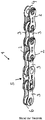
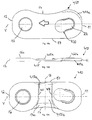
- FIG Figure 1 a section of a bicycle chain 1 known from the prior art with a conventional locking link 5.
- the chain 1 consists of alternating pairs of outer link plates 2 and inner link plates 3.
- the link plate pairs are connected in an articulated manner by means of chain rivets 4.
- a chain roller 6 is assigned to each chain rivet 4.
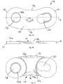
- Figure 1a and Figure 1b show the chain closure link 5 according to the invention in the non-assembled state.
- the two identical locking parts each consisting of a locking plate 10 and a chain pin 40, are rotated 180 degrees to one another and aligned for assembly.
- the Figure 1a shows a perspective view of the chain locking link 5.
- the insides of the two locking plates 10 face each other.
- the closure plates 10 each have a first end area 11 with an elongated hole 20 and a second end area 12 with a bolt hole 16.
- the arrow embossed in the connection area 15 located between the two end areas 11, 12 of the closure plate 10 shows the direction of chain travel and thus the mounting orientation of the closure link 10.
- the bolts 40 are each preassembled, in particular riveted, with their one end, the bolt foot 43, in a rotationally fixed manner in the bolt bore 16. At the other end of the The bolt head 41 rests on the bolt 40.
- Figure 1b shows a side view of the chain locking link 5 from FIG Figure 1a .
- the bolt 40 extends along its bolt longitudinal axis B.
- the bolt 40 tapers on the bolt neck 42 compared to the bolt body and bolt head 41.
- the bolt head 41 has a diameter D41 which is smaller than the diameter D21, the insertion opening 21 of the Long hole 20.
- the bolt head 41 of the one closure part can be inserted into the insertion opening 21 of the elongated hole 20 of the other closure part in each case.
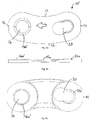
- Figure 2 shows the first assembly step of the closure member.
- the smaller-diameter bolt 40 of the one closure part is inserted into the larger-diameter insertion opening 21 of the other closure part in each case.
- the bolt 40 is positioned in the direction of the bolt longitudinal axis B in such a way that the bolt head 41 protrudes slightly beyond the outer surface of the closure plate 10.
- the two locking parts are inserted into one another without any effort.
- FIG 3 shows the subsequent second assembly step, in which the two locking parts are shifted against each other.
- the bolts 40 each move along the elongated hole 20 from the insertion opening 21 to the holding opening 22.
- the sliding movement takes place mainly in the direction of the longitudinal axis of the closure plates V, the bolt 40 only moves slightly in the direction of its longitudinal axis B.
- the bolt 40 passes a displacement area of the elongated hole 20.
- several bottlenecks are arranged which the bolt 40 has to overcome.
- the displacement movement of the bolt 40 can only take place under the action of force.
- the bolt 40 snaps or engages, so to speak, in the holding opening 22.
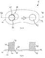
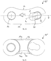
- FIGs 4a to 4d show the third assembly step and thus also the end position of the two locking parts.
- both bolts 40 are shown, only one closure plate 10 of the closure member 5 is shown.
- FIG 4a a top view of the fully assembled closure member 5 is shown.
- the bolt head 41 is in its end position in the holding opening 22 of the elongated hole 20.
- FIG. 3 is the sectional view of FIG Figure 4a along section line 4b-4b. It can be clearly seen here that the bolt head 41, after it has overcome the ramp 30, is arranged so deep in the elongated hole 20 that it does not or barely protrudes in the axial direction B beyond the outside of the closure plate.
- FIG. 3 is a sectional view of FIG Figure 4c along the section line 4d-4d, which runs through the bolt neck 42 just below the bolt head 41.
- the clamping area 27, which holds the bolt 40 in the holding opening 22 without play, is indicated here.
- the diameter D42 of the bolt neck 42 is slightly larger than the distance between the opposing slopes of the clamping area 27.
- the clamping slopes engage the bolt neck 42 and press the bolt 40 against the edge of the holding opening 22 in the direction of the first end area 11.
- the bolt 40 rests in the end position both on the edge of the holding opening 22 and on the two clamping slopes of the clamping area 27.
- the at least three contact points ensure a backlash-free clamping of the bolt 40 in its end position.
- Figure 5a is a detailed view of the elongated hole 20 in plan view - that is, the outside of the closure plate 10.
- the elongated hole 20 consists of an insertion opening 21 with a larger diameter, a displacement area and a smaller-diameter holding opening 22.
- the displacement area which lies between the two openings 21, 22, narrows in the direction of the holding opening 22.
- the insertion opening 21 describes a circular section with a diameter D21, which is dimensioned somewhat larger than the bolt head 41.
- the holding opening 22 also describes a circular section with a diameter D22, which corresponds to the diameter D41 of the bolt neck 41 or is slightly larger.
- the clamping area 27 adjoins the holding opening 22.
- the clamping area 27 is formed by two opposing and non-parallel clamping bevels 27a, 27b.
- a circle drawn with a dashed line is indicated with a diameter which corresponds approximately to the holding opening 22 or the bolt neck 41. It can be seen that the Clamping bevels 27a, 27b are clearly within the indicated circle and the bolt will therefore not have enough space in its end position. The lack of space leads to a slight deformation of the bolt and the locking plate during assembly. This elastic deformation clamps the bolt along the bolt neck in the elongated hole 20.
- the distance between the opposing clamping slopes 27a, 27b increases in the direction of the holding opening 22 from a distance A1 to a distance A2.
- the distance A1 between the two clamping bevels 27a, 27b corresponds at the same time to the neck constriction 26 in the displacement range of the elongated hole 20.
- the bolt neck must overcome this neck constriction 26 under the action of force before it then moves along the clamping bevels 27a, 27b in the assembly direction into the end position is pressed.
- the distance A1 is dimensioned somewhat smaller than the diameter D42 of the bolt neck.
- the distance A2 corresponds approximately to the diameter D42 of the bolt neck.
- the distance A3 corresponds to the head constriction 24 and is smaller than the diameter of the bolt head.
- the bolt head must also overcome this under the action of force.
- Both the narrow point to be overcome at the level of the bolt neck and the narrow point at the level of the bolt head result in a radial clamping of the bolt along the neck or the head.
- the two bottlenecks are arranged one behind the other in the assembly direction and each represent a dismantling lock.
- the insertion opening has a diameter of 3.75 mm and the holding opening has a diameter of 3 mm.
- the displacement area tapers in the assembly direction by 0.75 mm.
- the bolt head has a diameter of 3.64 mm and can therefore be easily inserted into the insertion opening.
- the bolt neck has a diameter of 2.93 mm and there is sufficient space in the holding opening.
- the starting distance A1 between the clamping bevels is 2.82 mm and the end distance A2 is 2.93 mm, so that the bolt neck is securely held in its end position.
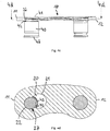
- Figure 6 shows a perspective sectional view of the closure plate 10 or the greatly enlarged elongated hole 20, on the basis of which the displacement of the bolt in the assembly direction can best be described.
- Figure 6 To the contour of the elongated hole 20 and to make the shifting area more visible in particular is shown in Figure 6 only one side of the elongated hole 20 is shown and the course of the bolt along this side of the elongated hole 20 shown is explained. Of course, the bolt moves along the other (not visible here) side of the elongated hole in the same way.
- the effect of the clamping bevels and constrictions can naturally only arise together with the side of the elongated hole, which is not shown here.
- the bolt head is first inserted into the insertion opening 21 of the elongated hole 20.
- the bolt head is then located in the upper half of the insertion opening 21 of the elongated hole 20 or a little above (cf. also Fig. 2 ).
- the “upper half” of the elongated hole is the area of the elongated hole that is closer to the outside of the closure plate 10.
- the outside of the closure plate 10 is shown in FIG Figure 6 up.
- the “lower half” of the elongated hole is correspondingly closer to the inside of the closure plate.
- the bolt head moves in the assembly direction due to the dimensions of the bolt and slot only in the upper half of the slot.
- the bolt neck moves accordingly in the lower half of the elongated hole.
- the lower half of the elongated hole only offers enough space for the bolt head in the area of the insertion opening 21, but not in the displacement area and in the area of the holding opening 22.
- the bolt is shifted in the assembly direction (along the elongated hole longitudinal axis L) in the direction of the holding opening 22 and passes through the displacement area between the insertion opening 21 and the holding opening 22 in several steps (see also FIG Fig. 3 ).
- the lateral edge of the bolt head slides under increasing force along the increasing head clamping slope 23a before it reaches the head constriction 24.
- the corresponding second head clamping slope (23b) is located on the opposite side of the elongated hole, which is not shown here.
- the head constriction 24 is formed by two opposing surfaces or edges in the upper half of the elongated hole 20.
- the distance A3 at the head constriction 24 is dimensioned smaller than the diameter D41 of the bolt head (cf. Figure 5b ). The bolt head can only overcome the head constriction 24 under the action of force.
- the underside of the bolt head slides over the ramp 30 before it rests in the bottom 31 of the countersink in its end position.
- the ramp 30 extends approximately perpendicular to the sides of the elongated hole 20.
- the bolt head after it has overcome the ramp 30, snaps in the direction of the bolt longitudinal axis B downwards onto the base 31 of the countersink.
- the ramp 30 first rises, then reaches a highest point and then falls again.
- the edge of the highest point of the ramp 30 is in Fig. 6 clearly visible.
- the level of the ramp 30 is so far above the base 31 of the countersink that this difference can only be overcome by means of increased force and the closure parts can be detached from one another.
- the bolt head rests against both the edge 29 and the base 31 of the depression.
- the edge of the holding opening 22 engages in the circumferential bolt groove or the bolt neck and the remainder of the bolt body extends below the closure plate 10 (cf. Fig. 4 ).
- the bolt is thus secured in the axial direction B.
- the ramp 30 is a further dismantling lock.
- the bolt neck moves along the lower half of the elongated hole 20.
- the bolt neck slides under increasing force along the rising neck clamping slope 25a before it reaches the neck constriction 26.
- the corresponding second neck clamping bevel 25b is located on the opposite side of the elongated hole 20, which is not shown here.
- the neck constriction 26 is formed by two opposing edges in the lower half of the elongated hole 20.
- the distance A1 at the neck constriction 26 is smaller than the diameter D42 of the bolt neck (cf. Figure 5b ). The bolt neck can only overcome the neck constriction 26 under the action of force.
- the clamping area 27 is formed by two opposing clamping slopes 27a, 27b.
- the two clamping bevels 27a, b do not run parallel to one another, but rather in the direction of the holding opening (i.e. in FIG Mounting direction) away from each other, so that their distance from each other increases. This has the effect that the bolt is pressed in the direction of the holding opening 22. In its end position, the bolt neck rests on both clamping bevels 27a, 27b and on the edge of the holding opening 22. In this way, the bolt is held or clamped in its end position without play in the closure plate 10.
- the clamping takes place in the radial direction of the bolt and represents a further dismantling protection.
- the two bottlenecks described above are at different heights. Furthermore, the constrictions are arranged one after the other in the assembly direction (from the insertion opening 21 in the direction of the holding opening 22). In the exemplary embodiment shown, the head constriction 24 lies in front of the neck constriction 26 in the assembly direction. That is, the bolt head must first pass the head constriction 24 before the bolt neck can pass the neck constriction 26.
- the bottlenecks could, however, also be arranged one above the other, so that they have to be overcome at the same time.
- the bolt After the bolt has overcome the two radial narrow points in the area of the bolt head and bolt neck and also the axial clamping effect of the ramp, it snaps into its end position and, due to the clamping area 27 according to the invention, lies against the closure plate 10 without play.
- the two bolts of the two locking parts overcome the respective dismantling locks at the same time, so that the locking parts are securely fixed in their end position without play.
- the assembly must accordingly take place under a relatively large force, which ideally can be defined and exerted in a controlled manner by means of an assembly tool.
- the various dismantling locks in the form of the narrow point at the level of the bolt neck and / or the narrow point at the level of the bolt head, the clamping surfaces at the level of the bolt neck and / or the clamping surfaces at the level of the bolt head (radial bolt clamping) and the ramp (axial bolt clamping) are separate from each other or can be used in combination with one another.
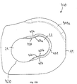
- FIG 7 shows a first embodiment of a closure plate 10 according to the invention
- Figure 7a the shape of the closure plate 10 can be clearly seen.
- the closure plate 10 is designed asymmetrically along its longitudinal axis V.
- the connecting region 15, which is arranged between the first end region 11 and the second end region 12, is not designed with a waist as in the prior art.
- the connection area 15 has a concave edge area 14 and a convex edge area 13.
- the elongated hole 20 and the bolt hole 16 with its countersink 16b can also be seen.
- the countersink 16b creates space for riveting the bolt base and takes up the deformed material of the bolt base.
- FIG. 7b The side view of the connecting plate 10 shown in the illustration clearly shows the recess 15a in the connecting area 15.
- the connection area 15 is clearly lowered compared to the two end areas 11, 12.
- the material thickness of the closure plate 10 in the region of the recess 15a is therefore less than in the end regions 11, 12.
- the recess 15a in the closure plate 10 facilitates the engagement of a tooth, even if the closure plates 10 are very close together in the assembled state.
- Figure 7a shows the inside of the closure plate 10.
- the recess 15a can also be clearly seen here.
- the recess 15a is delimited by the curved end regions 11, 12 and extends up to the edges 13 and 14. This results in a recess 15a which has a smaller width in the area of the longitudinal axis V of the closure plate than at the edge regions 13, 14.
- the transition between the recess 15a and the chamfers 13a and 14a is rounded. Between the depression 15a and the chamfers 13a, 14a there are preferably no edges but tangential transitions. The chamfers 13a and 14a along the edges further facilitate the penetration of the tooth.
- the pin bore 16 has a projection on the inside of the closure plate 10 16a on. This is created by the countersink 16b on the outside of the closure plate 10, because material is pressed through to the other side. The projection 16a increases the stability of the plate 10.
- the material thickness reduced due to the recess 15a and the associated reduced cross section of the closure plate 10 is compensated for by the changed outer contour of the closure plate 10.
- the convex edge 13 increases the cross section of the closure plate 10 and thus increases its stability.
- the closure plate 10 is produced from a flat starting material. The original material thickness is only found in the end areas 11, 12. In the connection area 15, something has been removed from the original material thickness, so that the recess 15a is created in particular by embossing.
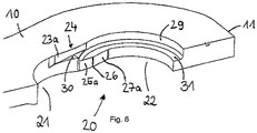
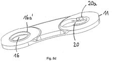
- Figure 8a-d shows a second embodiment of the closure plate 10 '.
- the enlarged countersink 16b ' can accommodate more deformed bolt material.
- the elongated hole 20 also has a projection 20a on the inside of the closure plate 10'.
- This projection 20a is also produced by material deformation of the plate 10 ′ and contributes to the stability in the area of the elongated hole 20.
- the projection 20a slopes down in the direction of the first end region 11 and can be seen particularly well in the side view and in perspective.
- Figure 9a 9b shows the outside and FIG. 9b the inside of a third embodiment of the closure plate 10 ′′.
- This closure plate 10 ′′ differs from the other two on account of its contour.
- one edge area 14 is concave and the other edge area 17 is straight.
- the concave edge area 14 follows the shape of the other outer and inner plates and the straight edge area 17 is a good compromise between stability and rolling behavior on the upper chain roller of the rear derailleur.
- the straight edge region 17 also has a bevel 17a, which enables a tooth to engage in the space between two opposing teeth Locking plates facilitated.
- the chamfers 13a, 14a, 17a in all embodiments form a kind of funnel shape with the largest possible clearance for the engaging teeth.
- Figure 10a shows a fourth embodiment of the closure plate 410 in plan view.
- the closure plate 410 likewise has a first and second end region 11, 12, a concave edge region 14 and a straight edge region 17 that runs essentially in a straight line.
- the bolt bore 16 and the elongated hole 420 largely correspond to the previous exemplary embodiments.
- the different dismantling locks of the fourth embodiment is referred to in connection with Figure 10d entered into more detail.
- the longitudinal axis V of the closure plate 410 runs through the center points of the bolt bore 16 and the holding opening 22.
- the straight edge region 17 extends parallel to the longitudinal axis V of the closure plate 410 Chamfer 411a arranged.
- the first bevel 411a improves the switching behavior of the chain.
- Figure 10b shows the fourth embodiment in a side view. Both the projection 16a on the bolt hole 16 and the projection 420a on the elongated hole 420 are visible here.
- the connecting area 415 or the recess 415a, which is lowered with respect to the end areas 11, 12, can also be seen.
- the additional material of the projections 16a and 420a leads to an increase in the cross section and thus to more stability and breaking resistance of the closure plate 410 in the area of the two openings 16, 420.
- Figure 10c shows the closure plate 410 in a view from below or the inside of the plate 410.
- the transverse axis Q of the closure plate 410 running perpendicular to the longitudinal axis V is also shown here.
- chamfers 417a and 14a are provided along the edge regions 17 and 14. They make it easier for a tooth to engage in the space between two opposing locking plates.
- the recess 415a is delimited on the one hand by the two end regions 11, 12 and, on the other hand, extends to the edge regions 14, 17.
- the course of the delimitations by the end regions 11, 12 or the first contour 418 differs the recess 415a and the second contour 419 of the recess 415a from the previous, continuously arcuate embodiments.
- the first contour 418 and the second contour 419 of the recess 415a run symmetrically with respect to the transverse axis Q.
- the contours 418, 419 of the recess 415a have a curved, tapering course from the concave edge region 14 towards the centrally located longitudinal axis V. They run essentially in a straight line from the longitudinal axis V to the straight edge region 17, i.e. parallel to the transverse axis Q.
- the recess 415a in the direction of the longitudinal axis V in the region of the straight edge region 17 is smaller than in the region of the concave edge region 14 the recess 415a is dimensioned smaller in the area near the longitudinal axis V than in the area near the concave edge area 14.
- the recess 415a is dimensioned approximately the same size in the area of the longitudinal axis V and in the area of the straight edge area 17. This has the advantage that more material at the edge region 17 leads to an increased cross-sectional area of the closure plate 410 and more stability. In comparison to this, the cross-sectional area of the previous exemplary embodiment is somewhat smaller due to the recess 15a (continuously arcuate contour of the recess) which increases in the direction of the concave edge region 14 and also in the direction of the straight edge region 17. The increased cross-section of the closure plate 410 due to the reduced recess 415a contributes to the somewhat reduced cross-section of a straight edge area 17 compared to a convex edge area 13 ( Figures 1a to 8 ) to compensate.
- the tooth engagement opening of the closure member is thus dimensioned larger at the concave edge areas 14 in the longitudinal direction of the closure plates 410 than on the side of the straight edge areas 17.
- the recess 15a on the non-concave edge 13, 17 is significantly larger than on the concave edge 14.
- the recess 415a, which is narrower at the edge regions 17, is nevertheless sufficiently large to ensure smooth operation.
- the bicycle chain 1 forms a closed chain loop, the links of which mesh with the teeth of the front chainring and the pinion and the lower and upper chain guide rollers of the rear derailleur run through in an S-shaped curve.
- the concave edge areas 14 of the locking link point in the direction of the teeth of the chainring, the pinion and also the lower chain guide roller.
- the upper chain guide roller Only when passing through the upper chain guide roller do the straight edge areas 17 and not the concave edge areas 14 point in the direction of the teeth of the upper chain guide roller.
- the upper chain guide roller usually has only one group of thin teeth, the axial width of which is matched to the tooth engagement openings of the inner plate pairs.
- the smaller-sized recess 415a of the locking link is therefore still sufficiently large in the area of the straight edge area 17 to be able to accommodate the teeth of the upper chain guide roller.
- FIG. 4 shows a detailed view of the elongated hole 420 from FIG Figure 10a .
- the various dismantling locks are clearly visible here.
- the fourth exemplary embodiment follows the previous ones insofar that those in connection with the Figures 5a and 5b described ratios of the bolt diameter to the elongated hole openings 21, 22 and to the distances A1, A2 and A3 accordingly are applicable.
- the closure plate 410 also has a head constriction 424, a neck constriction 426 and an adjoining clamping area 427 with two clamping bevels 427a, 427b.
- a bolt must first pass the neck constriction 426 and then the head constriction 424 during assembly (displacement of the bolt from the insertion opening 21 in the direction of the holding opening 22).
- a reverse order or arrangement of the bottlenecks would also be conceivable.
- a successive arrangement of the constrictions is positive in that the forces do not act simultaneously on the bolt head and bolt neck, but one after the other. But it would also be possible to arrange the two bottlenecks so that they are passed by the bolt at the same time.
- the base 431 of the countersink in the elongated hole 420 thus runs continuously on one plane. This means that the bottom of the bolt head slides along the base 431 of the countersink during the assembly of the chain locking link until the bolt has reached its end position in the holding opening 22. During assembly, the bolt must therefore first overcome the neck constriction 426 and then the head constriction 424. Subsequently, the bolt in the clamping area 427 is pressed by the two non-parallel clamping bevels 427a, 427b in the direction of the holding opening 22 (that is, in the assembly direction).
- the Figures 10e and 10f show a perspective top view and a perspective view from below of the closure plate 410.
- the different levels of the closure plate 410 are particularly clearly visible.
- the base 431 of the countersink of the elongated hole 420 and the countersink 16b of the bolt hole 16 are significantly deeper than the outer surface of the closure plate 410.
- the closure plate 410 thrown up material in the form of the projection 16a of the bolt hole 16 and the projection 420a of the elongated hole 420 is visible.
- the recess 415a in the connecting area of the closure plate 410 is clearly lowered compared to the end areas 11, 12.
- the bevels 411a, 14a and the sequence of the neck constriction 426 and head constriction 424 can also be clearly seen in perspective.
- Figure 11 shows a fifth embodiment of the closure plate 510 in plan view. This differs from the fourth embodiment only in that, in addition to the first bevel 511a on the first end area 11, it has a second bevel 512a on the second end area 12 on its outside.
- the two chamfers 511a and 512a are arranged in the direction of the concave edge region 14 or in the region between the end regions 11, 12 and the concave edge region 14.
- the bevels 511a, 512a slide along the teeth and improve the sliding in and out of the chain.
Landscapes
- Engineering & Computer Science (AREA)
- General Engineering & Computer Science (AREA)
- Mechanical Engineering (AREA)
- Connection Of Plates (AREA)
- Clamps And Clips (AREA)
- Chain Conveyers (AREA)
- Gears, Cams (AREA)
- Devices For Conveying Motion By Means Of Endless Flexible Members (AREA)
Description
Die vorliegende Erfindung betrifft ein Ketten-Verschlussglied für eine Antriebskette, die mit einem Mehrfachritzel mit großer Ganganzahl an einem Fahrradhinterrad zusammenwirkt.The present invention relates to a chain connecting link for a drive chain which cooperates with a multiple pinion with a large number of gears on a bicycle rear wheel.
Antriebsketten für Fahrräder mit Kettenschaltung setzen sich aus zueinander schwenkbar angeordneten Kettengliedern zusammen, mit deren Hilfe eine geschlossene Kettenschleife zur Antriebskraftübertragung ausgebildet wird. Diese Kettenglieder sind um Kettenbolzen relativ zueinander drehbar, wobei die Kettenbolzen von Lochungen aufgenommen werden, die sich in den zwei Endbereichen jeder Kettenlasche befinden. Die zwei Endbereiche jeder Kettenlasche sind durch einen Verbindungsbereich mit meistens tailliert ausgebildeter Außenkontur miteinander verbunden. Die Kettenglieder bestehen entweder aus einem Paar Innenlaschen oder einem Paar Außenlaschen. Die Außenlaschen- und Innenlaschenpaare sind in alternierender Weise mittels der Kettenbolzen miteinander verbunden. Aufgrund dieser Anordnung ist der Abstand zwischen einem Außenlaschenpaar etwas größer, als der zwischen einem Innenlaschenpaar.Drive chains for bicycles with derailleur gears are made up of chain links that are pivotably arranged with respect to one another, with the aid of which a closed chain loop is formed for the transmission of drive force. These chain links can be rotated relative to one another about chain pins, the chain pins being received by perforations which are located in the two end regions of each link plate. The two end areas of each link plate are connected to one another by a connection area with an outer contour that is mostly tapered. The chain links consist of either a pair of inner plates or a pair of outer plates. The outer link and inner link pairs are connected to one another in an alternating manner by means of the chain pins. Because of this arrangement, the distance between an outer plate pair is slightly larger than that between an inner plate pair.
Die Enden der Kettenschleife werden mittels eines Ketten-Verschlussglieds miteinander verbunden. Das Verschlussglied kann entweder wiederverschließbar oder nur einmal zu gebrauchen sein. Das Verschlussglied wird von einem Außenlaschenpaar gebildet, das sich allerdings durch einige Merkmale von den üblichen Außenlaschenpaaren unterscheidet.The ends of the chain loop are connected to one another by means of a chain connecting link. The closure member can either be resealable or can only be used once. The closure member is formed by a pair of outer plate, which, however, differs from the usual pairs of outer plates in some features.
Aus dem Stand der Technik sind verschiedene Ansätze bekannt, die die ungewollte Demontage des Verschlussgliedes verhindern sollen.Various approaches are known from the prior art, which are intended to prevent the unintentional dismantling of the closure member.
So stellt die
Des Weiteren offenbart die
Daher stellt sich die Aufgabe, ein Ketten-Verschlussgliedes bereitzustellen, das auch bei starker Belastung, beispielsweise bei starker Vibration oder Schlägen im unebenen Terrain, eine ungewollte Demontage des Ketten-Verschlussgliedes verhindert.Therefore, the task arises of providing a chain connecting link which prevents unintentional dismantling of the chain connecting link even under heavy loads, for example in the case of strong vibrations or impacts in uneven terrain.
Die vorliegende Erfindung löst diese Aufgabe mit einem Ketten-Verschlussglied nach dem Hauptanspruch, bestehend aus zwei Verschlussteilen mit jeweils einer Verschlussplatte und einem mit der Verschlussplatte drehfest verbundenen Kettenbolzen. Die Verschlussplatte weist einen ersten Endbereich, einen zweiten Endbereich und einen Verbindungsbereich zwischen den beiden Endbereichen auf. Ferner ist ein Langloch, umfassend eine Einführöffnung, eine Halteöffnung und einen zwischen der Einführöffnung und der Halteöffnung liegenden Verschiebebereich, in dem ersten Endbereich der Verschlussplatte angeordnet. Der Verschiebebereich verengt sich von der Einführöffnung hin zur Halteöffnung und bildet eine Hals-Engstelle. Der Kettenbolzen weist an einem Ende einen Bolzenkopf mit einem Bolzenhals und an dem anderen Ende einen Bolzenfuß auf. Ein Durchmesser D21 der Einführöffnung ist größer, als ein Durchmesser D41 des Bolzenkopfes 41. Ein Durchmesser D22 der Halteöffnung ist kleiner als der Durchmesser D41 des Bolzenkopfes, sowie größer als, oder zumindest genauso groß wie ein Durchmesser D42 des Bolzenhalses. Die Hals-Engstelle ist kleiner bemessen als der Durchmesser D42 des Bolzenhalses. Zwischen der Hals-Engstelle und der Halteöffnung des Langlochs ist ein Klemmbereich angeordnet, der kleiner bemessen ist, als der Durchmesser D42 des Bolzenhalses.The present invention solves this problem with a chain locking link according to the main claim, consisting of two locking parts, each with a locking plate and a chain pin connected non-rotatably to the locking plate. The closure plate has a first end area, a second end area and a connecting area between the two end areas. Furthermore, an elongated hole, comprising an insertion opening, a holding opening and a displacement area lying between the insertion opening and the holding opening, is arranged in the first end area of the closure plate. The displacement area narrows from the insertion opening towards the holding opening and forms a throat constriction. The chain pin has a pin head with a pin neck at one end and a pin base at the other end. A diameter D21 of the insertion opening is larger than a diameter D41 of the
Dies hat den Effekt, dass der Bolzen, wenn er die Engstelle im Verschiebebereich des Langlochs überwunden hat, mittels des Klemmbereichs in der Halteöffnung klemmend gehalten wird. Der Klemmbereich stellt eine weitere Demontagesicherung dar. Im Stand der Technik beschrieb die Halteöffnung bis zur Engstelle einen Kreisbogen mit einem Durchmesser, der etwas größer bemessen war als der Bolzenhalsdurchmesser. Der erfindungsgemäße Klemmbereich ist nunmehr zwischen dem Kreisbogen der Halteöffnung und der Engstelle angeordnet und erlaubt die spielfreie Klemmung des Bolzens gegen den Rand der Halteöffnung bzw. den Rand der Absenkung. Die Klemmung erfolgt in radialer Richtung auf den Bolzen, also quer zur Bolzenlängsachse des Bolzens B. Der Klemmbereich ist in der unteren Hälfte des Verschiebebereichs angeordnet.This has the effect that the bolt, when it has overcome the constriction in the displacement area of the elongated hole, is held in a clamping manner in the holding opening by means of the clamping area. The clamping area represents a further dismantling safeguard. In the prior art, the holding opening described an arc of a circle up to the narrow point with a diameter that was dimensioned somewhat larger than the diameter of the bolt neck. The clamping area according to the invention is now arranged between the circular arc of the holding opening and the constriction and allows the bolt to be clamped against the edge of the holding opening or the edge of the depression without play. The clamping takes place in the radial direction on the bolt, that is, transversely to the longitudinal axis of the bolt B. The clamping area is arranged in the lower half of the displacement area.
Insbesondere ist die Verschlussplatte entlang ihrer Längsachse V asymmetrisch ausgebildet und der Verbindungsbereich der Verschlussplatte weist einen konkaven Randbereich und einen nicht-konkaven Randbereich auf, wobei der nicht-konkave Randbereich als gerader Randbereich ausgebildet ist.In particular, the closure plate is designed asymmetrically along its longitudinal axis V and the connecting area of the closure plate has a concave edge area and a non-concave edge area, the non-concave edge area being designed as a straight edge area.
Ein positiver Effekt dieser asymmetrischen Ausbildung liegt darin, dass sich die Querschnittsfläche der Verschlussplatte vergrößert. Die Querschnittsfläche entspricht dabei der Fläche, die sichtbar wird, wenn die Verschlussplatte mittig entlang ihrer Querachse (senkrecht zu ihrer Längsachse V) geschnitten wird. Herkömmliche Verschlussplatten von Ketten-Verschlussgliedern weisen in der Regel, genau wie die übrigen Außenlaschen und Innenlaschen, einen symmetrischen und damit beidseitig, konkaven Verbindungsbereich auf (Vergleiche Abbildung des Stands der Technik).A positive effect of this asymmetrical design is that the cross-sectional area of the closure plate increases. The cross-sectional area corresponds to the area that becomes visible when the closure plate is cut centrally along its transverse axis (perpendicular to its longitudinal axis V). Conventional locking plates of chain locking links usually have, just like the other outer and inner plates, a symmetrical and thus concave connection area on both sides (compare illustration of the prior art).
Der Querschnitt einer auf beiden Seiten konkav ausgebildeten Verschlussplatte weist damit eine geringere Fläche auf, als eine Verschlussplatte mit einem weniger konkaven oder nicht konkaven Randbereich. Je weniger konkav der Randbereich ist, desto größer ist die Querschnittsfläche. Ein gerade ausgebildeter Randbereich weist einen größeren Querschnitt auf als ein konkav ausgebildeter, aber weniger als ein konvex ausgebildeter.The cross section of a closure plate that is concave on both sides thus has a smaller area than a closure plate with a less concave or non-concave edge region. The less concave the edge area, the larger the cross-sectional area. A straight edge area has a larger cross section than a concave but less than a convex.
Gerade bei schmal ausgeführten Ketten mit dünnen Verschlussplatten, wie sie bei hohen Gangzahlen nötig sind, ist es notwendig, eine ausreichend große Querschnittsfläche mit genügend Material bereitzustellen, um ausreichende Stabilität der Verschlussplatten zu gewährleisten.Particularly in the case of narrow chains with thin locking plates, as are necessary with high numbers of turns, it is necessary to provide a sufficiently large cross-sectional area with enough material to ensure sufficient stability of the locking plates.
Der gerade Randbereich stellt einen guten Kompromiss zwischen Stabilität und Abrollfähigkeit des Verschlussgliedes dar. Einerseits erhöhen sich die Stabilität und der Bruchwiderstand der Verschlussplatte aufgrund der im Vergleich zu einem konkaven Randbereich vergrößerten Querschnittsfläche der Verschlussplatte, andererseits verbessert sich das Abrollverhalten des Verschlussgliedes am oberen Kettenführungsröllchen gegenüber der Ausführung mit konvexem Randbereich.The straight edge area represents a good compromise between stability and unwinding ability of the closure link. On the one hand, the stability and the breaking resistance of the closure plate are increased due to the enlarged cross-sectional area of the closure plate compared to a concave edge area; Version with convex edge area.
In einem Ausführungsbeispiel wird der Klemmbereich von zwei sich gegenüberliegenden Klemmschrägen gebildet. Die beiden Klemmschrägen verlaufen zueinander nicht-parallel. Vielmehr laufen die beiden Klemmschrägen in Richtung der Halteöffnung (also in Montagerichtung) voneinander weg, so dass sich deren Abstand zueinander vergrößert. Dies hat den Effekt, dass der Bolzen in Richtung der Halteöffnung gedrückt wird. Der Abstand zwischen den beiden Klemmschrägen ist dabei so bemessen, dass der Abstand auch an der weitesten Stelle A2 noch kleiner ist, als der Durchmesser D42 des Bolzenhalses. Der Klemmbereich bzw. die Klemmschrägen sind in der unteren Hälfte des Verschiebebereichs angeordnet. Der Klemmbereich bzw. die Klemmschrägen wirken mit dem Bolzenhals zusammen.In one embodiment, the clamping area is formed by two opposing clamping slopes. The two clamping slopes are non-parallel to one another. Rather, the two clamping bevels run away from one another in the direction of the holding opening (that is, in the assembly direction), so that their distance from one another increases. This has the effect that the bolt is pushed in the direction of the retaining opening. The distance between the two clamping bevels is dimensioned such that the distance is even smaller at the widest point A2 than the diameter D42 of the bolt neck. The clamping area or the clamping bevels are arranged in the lower half of the displacement area. The clamping area or the clamping bevels interact with the bolt neck.
Ebenfalls denkbar wäre es, den Klemmbereich bzw. die gegenüberliegenden Klemmschrägen in der oberen Hälfte des Verschiebebereichs anzuordnen. Der Klemmbereich würde dann mit dem Bolzenkopf zusammenwirken. Der Abstand zwischen den Klemmschrägen wäre dann so bemessen, dass dieser auch an der weitesten Stelle noch kleiner wäre, als der Durchmesser des Bolzenkopfes. Der Bolzenkopf läge in seiner Endposition an beiden Klemmschrägen, als auch am Rand der Absenkung an. Damit würde der Bolzen ebenfalls in seiner Endposition spielfrei in der Verschlussplatte gehalten bzw. geklemmt.It would also be conceivable to arrange the clamping area or the opposing clamping bevels in the upper half of the displacement area. The clamping area would then interact with the bolt head. The distance between the clamping bevels would then be dimensioned so that it is also at the furthest point would be even smaller than the diameter of the bolt head. In its end position, the bolt head would rest on both clamping bevels and on the edge of the depression. In this way, the bolt would also be held or clamped in its end position without play in the closure plate.
Eine Kombination von Klemmbereichen in Höhe des Bolzenhalses und in Höhe des Bolzenkopfes wäre ebenfalls denkbar.A combination of clamping areas at the level of the bolt neck and at the level of the bolt head would also be conceivable.
In einem Ausführungsbeispiel weist das Langloch in seinem Verschiebebereich eine Rampe auf. Der Bolzenkopf gleitet mit seiner Unterseite bei der Montage des Ketten-Verschlussgliedes entlang der Rampe, wobei die Rampe entlang des Verschiebebereichs, in Richtung der Halteöffnung ansteigt. Die Rampe stellt eine zusätzliche Demontagesicherung dar. Der Bolzenkopf muss die Steigung der Rampe und damit deren Klemmwirkung in axialer Richtung des Bolzens überwinden, bevor er seine Endposition erreicht.In one embodiment, the elongated hole has a ramp in its displacement area. The bolt head slides with its underside during the assembly of the chain locking link along the ramp, the ramp rising along the displacement area in the direction of the holding opening. The ramp represents an additional dismantling protection. The bolt head must overcome the slope of the ramp and thus its clamping effect in the axial direction of the bolt before it reaches its end position.
In einem Ausführungsbeispiel verengt sich der Verschiebebereich des Langlochs von der Einführöffnung hin zur Halteöffnung an einer weiteren Stelle, so dass sich neben der Hals-Engstelle auch eine Kopf-Engstelle bildet. Die Kopf-Engstelle ist dabei kleiner bemessen, als der Durchmesser des Bolzenkopfes. Die zusätzliche Kopf-Engstelle stellt eine weitere Demontagesicherung für das Verschlussglied dar.In one embodiment, the displacement area of the elongated hole narrows from the insertion opening towards the holding opening at a further point, so that a head constriction is also formed in addition to the neck constriction. The head constriction is dimensioned smaller than the diameter of the bolt head. The additional head constriction represents a further dismantling protection for the locking link.
In einem Ausführungsbeispiel verläuft eine Langloch-Längsachse L des Langlochs schräg zur Verschlussplatten-Längsachse V.In one embodiment, an elongated hole longitudinal axis L of the elongated hole runs obliquely to the closure plate longitudinal axis V.
Insbesondere verläuft die Langloch-Längsachse L in einem Winkelbereich von 5 Grad bis 25 Grad, vorzugsweise von 15 Grad, zur Verschlussplatten-Längsachse V.In particular, the elongated hole longitudinal axis L extends in an angular range of 5 degrees to 25 degrees, preferably 15 degrees, to the closure plate longitudinal axis V.
Diese Schrägstellung des Langlochs gegenüber der Verschlussplatten-Längsachse V stellt sicher, dass um das Langloch herum genügend Material, also genügend Abstand zu den Rändern der Verschlussplatte besteht. Damit bleibt die Stabilität der Verschlussplatte erhalten.This inclined position of the elongated hole with respect to the longitudinal axis V of the closure plate ensures that there is enough material around the elongated hole, that is, there is sufficient distance from the edges of the closure plate. This maintains the stability of the closure plate.
In einem Ausführungsbeispiel weist der Verbindungsbereich der Verschlussplatte eine Aussparung auf. Die Aussparung erlaubt eine besonders schmale Kettenbauweise, weil die Verschlussplatten sehr nah zusammengebracht werden können und dennoch genügend Platz für den Eingriff der Zähne bleibt.In one embodiment, the connection area of the closure plate has a recess. The recess allows a particularly narrow chain design because the locking plates can be brought very close together and still enough space remains for the teeth to engage.
Die Aussparung kann durch Prägen oder Fräsen hergestellt werden. Vorzugsweise bleibt die Außenseite der Verschlussplatte dabei flach. So wird verhindert, dass die Außenseite der Verschlussplatte beim Wechsel von einem Zahnrad aufs nächste ungewollt mit Zähnen oder anderen Bauteilen kollidiert.The recess can be produced by embossing or milling. The outside of the closure plate preferably remains flat. This prevents the outside of the closure plate from inadvertently colliding with teeth or other components when changing from one gear wheel to the next.
Dies ist eine besonders dünne Ausführungsform der Verschlussplatte, was umso mehr nach einer vergrößerten Querschnittsfläche und damit einem nicht-konkaven Randbereich verlangt. Es ist aber auch denkbar, dass durch das Prägen Material auf die Außenseite gedrückt wird, was zu einer nicht-flachen Außenseite führt.This is a particularly thin embodiment of the closure plate, which calls for an enlarged cross-sectional area and thus a non-concave edge area all the more. However, it is also conceivable that the embossing presses material onto the outside, which leads to a non-flat outside.
In einer Ausführungsform ist die Aussparung in Richtung der Längsachse der Verschlussplatte gesehen im Bereich des geraden Randbereichs geringer bemessen, als im Bereich des konkaven Randbereichs. Dies hat den Effekt, dass die Querschnittsfläche der Verschlussplatte aufgrund der verkleinerten Aussparung weiter erhöht wird, was wiederum die Stabilität der Verschlussplatte erhöht.In one embodiment, the recess, viewed in the direction of the longitudinal axis of the closure plate, is dimensioned smaller in the area of the straight edge area than in the area of the concave edge area. This has the effect that the cross-sectional area of the closure plate is increased further due to the reduced recess, which in turn increases the stability of the closure plate.
Insbesondere weisen die relativ zur Querachse der Verschlussplatte symmetrisch verlaufenden Konturen der Aussparung vom konkaven Randbereich hin zur mittig gelegenen Verschlussplatten-Längsachse einen gebogenen, sich verjüngenden Verlauf auf. Von der Verschlussplatten-Längsachse zum geraden Randbereich hin verlaufen die Konturen im Wesentlichen geradlinig, also parallel zur Querachse der Verschlussplatte. Somit ist die Aussparung in Richtung der Verschlussplatten-Längsachse gesehen im Bereich des geraden Randbereichs und im Bereich nahe der Verschlussplatten-Längsachse geringer bemessen, als im Bereich des konkaven Randbereichs.In particular, the contours of the recess, which run symmetrically relative to the transverse axis of the closure plate, have a curved, tapering course from the concave edge region towards the centrally located closure plate longitudinal axis. From the longitudinal axis of the closure plate to the straight edge area, the contours run essentially in a straight line, that is, parallel to the transverse axis of the closure plate. Thus, viewed in the direction of the longitudinal axis of the closure plate, the recess is dimensioned smaller in the area of the straight edge area and in the area near the longitudinal axis of the closure plate than in the area of the concave edge area.
Bei der Weiterentwicklung von Kettenschaltsystemen für Fahrräder hat sich die Anzahl der Ritzel am Mehrfachritzel schrittweise immer weiter erhöht. Damit einhergegangen sind Veränderungen der Abmessungen von Ritzeln, Kettenlaschen, Kettenbolzen und Kettenrollen, vor allem der Abmessungen in der Richtung parallel zur Längsachse der Kettenbolzen in axialer Richtung. Damit wird die Kette an die in einem immer geringeren axialen Abstand zueinander an der Hinterradnabe platzierten hinteren Ritzel angepasst. Dabei ist klar, dass die in axialer Richtung über die Außenseite der Kette vorstehenden Bestandteile der Kette auch hinderlich sind, weil sie ungewollt und störend in Kontakt mit Bestandteilen des benachbarten Ritzels geraten können. Eine Reduzierung der Abmessungen der Bestandteile der Kette, verlangt auch eine Anpassung des Verschlussgliedes an eine besonders schmale Kette.With the further development of derailleur systems for bicycles, the number of sprockets on multiple sprockets has increased step by step. This has been accompanied by changes in the dimensions of pinions, link plates, chain pins and chain rollers, especially the dimensions in the parallel direction to the longitudinal axis of the chain pins in the axial direction. In this way, the chain is adapted to the rear sprockets, which are placed on the rear wheel hub at an ever smaller axial distance from one another. It is clear that the components of the chain protruding in the axial direction over the outside of the chain are also a hindrance because they can come into contact with components of the adjacent pinion in an unintentional and disruptive manner. A reduction in the dimensions of the components of the chain also requires the closure link to be adapted to a particularly narrow chain.
Eine weitere Aufgabe der Erfindung liegt somit darin, ein Verschlussglied bereitzustellen, dass sowohl eine schmale Bauweise mit wenig Abstand zwischen den Verschlussplatten und ein sicheres Eingreifen der Zähne zwischen die Verschlussplatten erlaubt, als auch genügend Stabilität und Demontagesicherheit bietet.A further object of the invention is thus to provide a closure member that allows both a narrow design with little spacing between the closure plates and a secure engagement of the teeth between the closure plates, and also offers sufficient stability and dismantling security.
Aus dem Stand der Technik sind bereits gebogene bzw. bananenförmige Verschlussglieder bekannt, beispielsweise aus der
Die Aussparung im Verbindungsbereich führt zu einer Absenkung gegenüber dem ersten und zweiten Endbereich der Verschlussplatte. Die Absenkung schafft damit auch bei einer engen Kettenbauweise genügend Platz, um die Zähne der Kettenblätter bzw. Ritzel eingreifen zu lassen. Dies ist besonders bei Antrieben mit nur einem Kettenblatt und einer erhöhten Anzahl von etwa 12 Ritzeln notwendig. Insbesondere weisen solche Antriebe häufig alternierende dicke und dünne Zähne am vorderen Kettenrad und/oder den hinteren Ritzeln auf. In diesem Fall schafft die Aussparung genügend Platz, damit auch ein solcher dicker Zahn in den Zwischenraum des Verschlussgliedes eingreifen kann.The recess in the connection area leads to a lowering in relation to the first and second end areas of the closure plate. The lowering creates enough space, even with a narrow chain design, to allow the teeth of the chainrings or sprockets to engage. This is particularly necessary for drives with only one chainring and an increased number of around 12 sprockets. In particular, such drives often have alternating thick and thin teeth on the front sprocket and / or the rear pinions. In this case, the recess creates enough space so that such a thick tooth can also engage in the intermediate space of the closure member.
Der gerade Randbereich stellt einen guten Kompromiss zwischen Stabilität und Abrollfähigkeit des Verschlussgliedes dar. Einerseits erhöhen sich die Stabilität und der Bruchwiderstand der Verschlussplatte aufgrund der im Vergleich zu einem konkaven Randbereich vergrößerten Querschnittsfläche der Verschlussplatte; andererseits verbessert sich das Abrollverhalten des Verschlussgliedes am oberen Kettenführungsröllchen gegenüber der Ausführung mit konvexem Randbereich.The straight edge area represents a good compromise between stability and rollability of the closure member. On the one hand, the stability and the breaking resistance of the closure plate increase due to the enlarged cross-sectional area of the closure plate compared to a concave edge area; on the other hand, the rolling behavior of the locking link on the upper chain guide roller improves compared to the version with a convex edge area.
In einer Ausführungsform ist die Aussparung in Richtung der Längsachse der Verschlussplatte gesehen im Bereich des geraden Randbereichs geringer bemessen, als im Bereich des konkaven Randbereichs. Dies hat den Effekt, dass die Querschnittsfläche der Verschlussplatte aufgrund der verkleinerten Aussparung weiter erhöht wird, was wiederum die Stabilität der Verschlussplatte erhöht.In one embodiment, the recess, viewed in the direction of the longitudinal axis of the closure plate, is dimensioned smaller in the area of the straight edge area than in the area of the concave edge area. This has the effect that the cross-sectional area of the closure plate is increased further due to the reduced recess, which in turn increases the stability of the closure plate.
Insbesondere weisen die relativ zur Querachse der Verschlussplatte symmetrisch verlaufenden Konturen der Aussparung vom konkaven Randbereich hin zur mittig gelegenen Verschlussplatten-Längsachse einen gebogenen, sich verjüngenden Verlauf auf. Von der Verschlussplatten-Längsachse zum geraden Randbereich hin verlaufen die Konturen im Wesentlichen geradlinig, also parallel zur Querachse der Verschlussplatte. Somit ist die Aussparung in Richtung der Verschlussplatten-Längsachse gesehen im Bereich des geraden Randbereichs und im Bereich nahe der Verschlussplatten-Längsachse geringer bemessen, als im Bereich des konkaven Randbereichs.In particular, the contours of the recess, which run symmetrically relative to the transverse axis of the closure plate, have a curved, tapering course from the concave edge region towards the centrally located closure plate longitudinal axis. From the longitudinal axis of the closure plate to the straight edge area, the contours run essentially in a straight line, that is, parallel to the transverse axis of the closure plate. Thus, viewed in the direction of the longitudinal axis of the closure plate, the recess is dimensioned smaller in the area of the straight edge area and in the area near the longitudinal axis of the closure plate than in the area of the concave edge area.
Gleichzeitig gewährt die Demontagesicherung in Form einer Kopf-Engstelle und/oder Hals-Engstelle erhöhte Demontagesicherheit.At the same time, the dismantling safeguard in the form of a head constriction and / or neck constriction ensures increased dismantling safety.
In einer Ausführungsform ist zwischen der Kopf-Engstelle und der Halteöffnung des Langlochs ein Klemmbereich angeordnet, der kleiner bemessen ist, als der Durchmesser D41 des Bolzenkopfes. Alternativ oder zusätzlich zu dem Klemmbereich ist ein weiterer Klemmbereich zwischen der Hals-Engstelle und der Halteöffnung des Langlochs angeordnet, der kleiner bemessen ist, als der Durchmesser D42 des Bolzenhalses.In one embodiment, a clamping area is arranged between the head constriction and the holding opening of the elongated hole, which is dimensioned smaller than the diameter D41 of the bolt head. As an alternative or in addition to the clamping area, a further clamping area is arranged between the neck constriction and the holding opening of the elongated hole, which is dimensioned smaller than the diameter D42 of the bolt neck.
Der Klemmbereich stellt eine weitere Demontagesicherung dar. Weiter hat es den Effekt, dass der Bolzen, wenn er die Engstelle im Verschiebebereich des Langlochs überwunden hat, mittels des Klemmbereichs in der Halteöffnung klemmend und spielfrei gehalten wird. Der Klemmbereich kann dabei in Höhe des Bolzenhalses (in der unteren Hälfte des Verschiebebereichs) und/oder des Bolzenkopfes (in der oberen Hälfte des Verschiebeberichs) angeordnet werden.The clamping area represents a further dismantling safeguard. It also has the effect that the bolt, when it has overcome the constriction in the displacement area of the elongated hole, is held in the holding opening in a clamping and play-free manner by means of the clamping area. The clamping area can be arranged at the level of the bolt neck (in the lower half of the displacement area) and / or the bolt head (in the upper half of the displacement area).
In den von dem Nebenanspruch abhängigen Ansprüchen sind weitere Merkmale beschrieben, deren Effekte die gleichen sind, wie die bereits in Zusammenhang mit den vom Hauptanspruch abhängigen Ansprüchen beschrieben wurden.In the claims dependent on the independent claim, further features are described, the effects of which are the same as those already described in connection with the claims dependent on the main claim.
Die vorliegende Erfindung wird mit Bezug auf die beigefügten Zeichnungen detailliert beschrieben, wobei die Ausführungsbeispiele lediglich als nicht-beschränkende Beispiele für das erfindungsgemäße Ketten-Verschlussglied anzusehen sind.
- Fig. 1
- zeigt den Stand der Technik
- Fig. 1a
- zeigt eine perspektivische Ansicht des erfindungsgemäßen Ketten-Verschlussgliedes im nicht montieren Zustand
- Fig. 1b
- zeigt eine Seitenansicht des Ketten-Verschlussgliedes aus
Fig. 1a - Fig. 2
- zeigt den ersten Montageschritt
- Fig. 3
- zeigt den zweiten Montageschritt
- Fig. 4a
- zeigt den dritten Montageschritt - Endposition in einer Draufsicht
- Fig. 4b
- zeigt eine Schnittansicht der
Fig. 4a entlang der Schnittlinie 4b-4b - Fig. 4c
- zeigt eine Seitenansicht der
Fig. 4a - Fig. 4d
- zeigt eine Schnittansicht der
Fig. 4c entlang der Schnittlinie 4d-4d - Fig. 5a, b
- zeigen eine Detailansicht des Langlochs in der Draufsicht
- Fig. 6
- zeigt eine Detailansicht des Langlochs in der geschnittenen Perspektive
- Fig. 7a
- zeigt eine erste Ausführungsform der Verschlussplatte in der Draufsicht
- Fig. 7b
- zeigt
Fig. 7a in einer Seitenansicht - Fig. 7c
- zeigt
Fig. 7a in der Unteransicht - Fig. 8a
- zeigt eine zweite Ausführungsform der Verschlussplatte in der Draufsicht
- Fig. 8b
- zeigt
Fig. 8a in einer Seitenansicht - Fig. 8c
- zeigt
Fig. 8a in der Unteransicht - Fig. 8d
- zeigt
Fig. 8a in der Perspektive - Fig. 9a
- zeigt eine dritte Ausführungsform der Verschlussplatte in der Draufsicht
- Fig. 9b
- zeigt
Fig. 9a in der Unteransicht - Fig. 10a
- zeigt eine vierte Ausführungsform der Verschlussplatte in der Draufsicht
- Fig. 10b
- zeigt
Fig. 10a in einer Seitenansicht - Fig. 10c
- zeigt
Fig. 10c in der Unteransicht - Fig. 10d
- zeigt eine Detailansicht des Langlochs aus
Fig. 10a - Fig. 10e
- zeigt eine perspektivische Draufsicht der vierten Ausführungsform
- Fig. 10f
- zeigt eine perspektivische Unteransicht der vierten Ausführungsform
- Fig. 11
- zeigt eine fünfte Ausführungsform der Verschlussplatte in der Draufsicht
- Fig. 1
- shows the state of the art
- Fig. 1a
- shows a perspective view of the chain connecting link according to the invention in the non-assembled state
- Figure 1b
- FIG. 11 shows a side view of the chain locking link from FIG
Fig. 1a - Fig. 2
- shows the first assembly step
- Fig. 3
- shows the second assembly step
- Figure 4a
- shows the third assembly step - end position in a plan view
- Figure 4b
- FIG. 11 shows a sectional view of FIG
Figure 4a along section line 4b-4b - Figure 4c
- shows a side view of the
Figure 4a - Figure 4d
- FIG. 11 shows a sectional view of FIG
Figure 4c alongsection line 4d-4d - Fig. 5a, b
- show a detailed view of the elongated hole in plan view
- Fig. 6
- shows a detailed view of the elongated hole in the cut perspective
- Figure 7a
- shows a first embodiment of the closure plate in plan view
- Figure 7b
- shows
Figure 7a in a side view - Figure 7c
- shows
Figure 7a in the bottom view - Figure 8a
- shows a second embodiment of the closure plate in plan view
- Figure 8b
- shows
Figure 8a in a side view - Figure 8c
- shows
Figure 8a in the bottom view - Figure 8d
- shows
Figure 8a in perspective - Figure 9a
- shows a third embodiment of the closure plate in plan view
- Figure 9b
- shows
Figure 9a in the bottom view - Figure 10a
- shows a fourth embodiment of the closure plate in plan view
- Figure 10b
- shows
Figure 10a in a side view - Figure 10c
- shows
Figure 10c in the bottom view - Fig. 10d
- shows a detailed view of the elongated hole
Figure 10a - Figure 10e
- Figure 13 shows a top perspective view of the fourth embodiment
- Fig. 10f
- Fig. 13 is a bottom perspective view of the fourth embodiment
- Fig. 11
- shows a fifth embodiment of the closure plate in plan view
Die Begriffe "oben" und "unten" beziehen sich unter anderem auf die Richtung der Bolzenlängsachse B, wobei der Bolzenkopf 41 weiter oben als der Bolzenhals 42, und der Bolzenfuß 43 weiter unten als der Bolzenhals 42 angeordnet ist. Die Begriffe "innen" und "außen" beziehen sich auf die Seiten der Verschlussplatten. Die Innenflächen der Verschlussplatten sind sich im montierten Zustand des Verschlussgliedes zugewandt. Die Außenflächen der Verschlussplatten sind im montierten Zustand des Verschlussgliedes voneinander abgewandt. Die Begriffe werden gleichermaßen im Zusammenhang mit den Bolzen und den Verschlussplatten genutzt.The terms “up” and “down” relate, among other things, to the direction of the bolt longitudinal axis B, the
Zum besseren Verständnis der Erfindung zeigt die erste Abbildung in
In den
Für ein besseres Verständnis zeigen die
In einer besonders bevorzugten Ausführungsform hat die Einführöffnung einen Durchmesser von 3,75 mm und die Halteöffnung einen Durchmesser von 3 mm. Der Verschiebebereich verjüngt sich also in Montagerichtung um 0,75 mm. Der Bolzenkopf weist einen Durchmesser von 3,64 mm auf und kann damit leicht in die Einführöffnung geführt werden. Der Bolzenhals weist einen Durchmesser von 2,93 mm auf und findet ausreichend Platz in der Halteöffnung. Der Anfangsabstand A1 zwischen den Klemmschrägen beträgt 2,82 mm und der Endabstand A2 2,93 mm, so dass der Bolzenhals sicher in seiner Endposition gehalten wird.In a particularly preferred embodiment, the insertion opening has a diameter of 3.75 mm and the holding opening has a diameter of 3 mm. The displacement area tapers in the assembly direction by 0.75 mm. The bolt head has a diameter of 3.64 mm and can therefore be easily inserted into the insertion opening. The bolt neck has a diameter of 2.93 mm and there is sufficient space in the holding opening. The starting distance A1 between the clamping bevels is 2.82 mm and the end distance A2 is 2.93 mm, so that the bolt neck is securely held in its end position.
Im ersten Montageschritt wird der Bolzenkopf zunächst in die Einführöffnung 21 des Langlochs 20 gesteckt. Der Bolzenkopf befindet sich dann in der oberen Hälfte der Einführöffnung 21 des Langlochs 20 oder etwas darüber (vgl. auch
Die "obere Hälfte" des Langlochs ist der Bereich des Langlochs, der näher an der Außenseite der Verschlussplatte 10 liegt. Die Außenseite der Verschlussplatte 10 zeigt in
Der Bolzen wird im zweiten Montageschritt in Montagerichtung (entlang der Langloch-Längsachse L) Richtung Halteöffnung 22 verschoben und passiert dabei in mehreren Schritten den Verschiebebereich zwischen der Einführöffnung 21 und der Halteöffnung 22 (vgl. auch
Zuerst gleitet der seitliche Rand des Bolzenkopfes unter ansteigender Krafteinwirkung entlang der ansteigenden Kopf-Klemmschräge 23a, bevor er die Kopf-Engstelle 24 erreicht. Auf der hier nicht dargestellten gegenüberliegenden Seite des Langlochs befindet sich die entsprechende zweite Kopf-Klemmschräge (23b). Nachdem der Bolzenkopf die Kopf-Engstelle 24 überwunden hat, liegt er in seiner Endposition am Rand 29 der Ansenkung an. Die Kopf-Engstelle 24 wird von zwei sich gegenüberliegenden Flächen oder Kanten in der oberen Hälfte des Langlochs 20 gebildet. Der Abstand A3 an der Kopf-Engstelle 24 ist geringer bemessen als der Durchmesser D41 des Bolzenkopfes (vgl.
Gleichzeitig mit der oben beschriebenen Montagebewegung des seitlichen Bolzenkopfrandes entlang der Seiten des Langlochs, gleitet die Unterseite des Bolzenkopfes über die Rampe 30, bevor sie im Grund 31 der Ansenkung in ihrer Endposition anliegt. Die Rampe 30 erstreckt sich in etwa senkrecht zu den Seiten des Langlochs 20. Der Bolzenkopf schnappt, nachdem er die Rampe 30 überwunden hat, in Richtung der Bolzenlängsachse B nach unten auf den Grund 31 der Ansenkung. Die Rampe 30 steigt dabei zunächst an, erreicht dann eine höchste Stelle und fällt danach wieder ab. Die Kante der höchsten Stelle der Rampe 30 ist in
Gleichzeitig mit der oben beschriebenen Montagebewegung des Bolzenkopfes bewegt sich der Bolzenhals entlang der unteren Hälfte des Langlochs 20. Zuerst gleitet der Bolzenhals unter ansteigender Krafteinwirkung entlang der ansteigenden Hals-Klemmschräge 25a, bevor er die Hals-Engstelle 26 erreicht. Auf der hier nicht dargestellten gegenüberliegenden Seite des Langlochs 20 befindet sich die entsprechende zweite Hals-Klemmschräge 25b. Die Hals-Engstelle 26 wird von zwei sich gegenüberliegenden Kanten in der unteren Hälfte des Langlochs 20 gebildet. Der Abstand A1 an der Hals-Engstelle 26 ist geringer bemessen, als der Durchmesser D42 des Bolzenhalses (vgl.
Die beiden oben beschriebenen Engstellen liegen auf verschiedenen Höhen. Des Weiteren sind die Engstellen in Montagerichtung (von der Einführöffnung 21 in Richtung Halteöffnung 22) nacheinander angeordnet. Im gezeigten Ausführungsbeispiel liegt die Kopf-Engstelle 24 in Montagerichtung vor der Hals-Engstelle 26. Das heißt der Bolzenkopf muss zuerst die Kopf-Engstelle 24 passieren, bevor der Bolzenhals die Hals-Engstelle 26 passieren kann. Die Engstellen könnten aber auch übereinander angeordnet sein, so dass sie gleichzeitig überwunden werden müssen.The two bottlenecks described above are at different heights. Furthermore, the constrictions are arranged one after the other in the assembly direction (from the
Nachdem der Bolzen die beiden radialen Engstellen im Bereich des Bolzenkopfes und Bolzenhalses und auch die axiale Klemmwirkung der Rampe überwunden hat, schnappt er in seiner Endposition ein und liegt aufgrund des erfindungsgemäßen Klemmbereichs 27 spielfrei an der Verschlussplatte 10 an.After the bolt has overcome the two radial narrow points in the area of the bolt head and bolt neck and also the axial clamping effect of the ramp, it snaps into its end position and, due to the clamping
Während der Montage überwinden die beiden Bolzen der beiden Verschlussteile gleichzeitig die jeweiligen Demontagesicherungen, so dass die Verschlussteile in ihrer Endposition spielfrei und sicher festgelegt sind. Die Montage muss entsprechend unter einer relativ großen Krafteinwirkung erfolgen, die idealerweise mittels einem Montagewerkzeug definiert und kontrolliert ausgeübt werden kann.During assembly, the two bolts of the two locking parts overcome the respective dismantling locks at the same time, so that the locking parts are securely fixed in their end position without play. The assembly must accordingly take place under a relatively large force, which ideally can be defined and exerted in a controlled manner by means of an assembly tool.
In Demontagerichtung (von der Halteöffnung 22 in Richtung der Einführöffnung 21) müssen ebenfalls alle oben beschriebenen Demontagesicherungen überwunden werden, was mindestens so viel Krafteinwirkung wie die Montage verlangt. Auch für die Demontage ist ein entsprechendes Werkzeug notwendig. Während der Fahrt werden auch bei stärksten Belastungen solch hohe Kräfte äußerst selten erreicht, so dass ein stabiler Verschluss der Kette gewährleistet ist.In the dismantling direction (from the holding
Die verschiedenen Demontagesicherungen in Form der Engstelle auf Höhe des Bolzenhalses und/oder der Engstelle auf Höhe des Bolzenkopfes, der Klemmflächen in Höhe des Bolzenhalses und/oder der Klemmflächen in Höhe des Bolzenkopfes (radiale Bolzenklemmung) und die Rampe (axiale Bolzenklemmung) sind getrennt voneinander oder in Kombination miteinander anwendbar.The various dismantling locks in the form of the narrow point at the level of the bolt neck and / or the narrow point at the level of the bolt head, the clamping surfaces at the level of the bolt neck and / or the clamping surfaces at the level of the bolt head (radial bolt clamping) and the ramp (axial bolt clamping) are separate from each other or can be used in combination with one another.
Die aufgrund der Aussparung 15a reduzierte Materialstärke und der damit einhergehende reduzierte Querschnitt der Verschlussplatte 10 wird durch die geänderte Außenkontur der Verschlussplatte 10 ausgeglichen. Der konvexe Rand 13 erhöht den Querschnitt der Verschlussplatte 10 und steigert damit deren Stabilität. Die Verschlussplatte 10 wird aus einem ebenen Ausgangsmaterial hergestellt. Die ursprüngliche Materialdicke findet sich lediglich noch in den Endbereichen 11, 12. Im Verbindungsbereich 15 ist von der ursprünglichen Materialdicke etwas weggenommen, so dass die Aussparung 15a insbesondere durch Prägen geschaffen wird.The material thickness reduced due to the
Außerdem ist in
Die erste Kontur 418 und die zweite Kontur 419 der Ausnehmung 415a verlaufen bezüglich der Querachse Q symmetrisch. Die Konturen 418, 419 der Aussparung 415a weisen vom konkaven Randbereich 14 hin zur mittig gelegenen Längsachse V einen gebogenen, sich verjüngenden Verlauf auf. Von der Längsachse V zum geraden Randbereich 17 hin verlaufen sie im Wesentlichen geradlinig, also parallel zur Querachse Q. Somit ist die Aussparung 415a in Richtung der Längsachse V im Bereich des geraden Randbereichs 17 geringer bemessen, als im Bereich des konkaven Randbereichs 14. Außerdem ist die Aussparung 415a im Bereich nahe der Längsachse V geringer bemessen, als im Bereich nahe des konkaven Randbereichs 14. Die Aussparung 415a ist im Bereich der Längsachse V und im Bereich des geraden Randbereichs 17 in etwa gleich groß bemessen. Das hat den Vorteil, dass mehr Material am Randbereich 17 zu einer erhöhten Querschnittsfläche der Verschlussplatte 410 und mehr Stabilität führt. Im Vergleich dazu ist die Querschnittsfläche des vorherigen Ausführungsbeispiels aufgrund der sich in Richtung des konkaven Randbereichs 14 und auch in Richtung des geraden Randbereichs 17 hin vergrößernden Aussparung 15a (durchgängig bogenförmige Kontur der Aussparung) etwas geringer. Der aufgrund der verkleinerten Aussparung 415a erhöhte Querschnitt der Verschlussplatte 410 trägt dazu bei, den etwas reduzierten Querschnitt eines geraden Randbereichs 17 im Vergleich zu einem konvexen Randbereich 13 (
Die Zahneingriffsöffnung des Verschlussgliedes ist somit an den konkaven Randbereichen 14 in Längsrichtung der Verschlussplatten 410 größer bemessen, als auf der Seite der geraden Randbereiche 17. Bei den vorhergehenden Ausführungsbeispielen ist die Aussparung 15a am nicht-konkaven Rand 13, 17 deutlich größer bemessen, als am konkaven Rand 14. Die an den Randbereichen 17 schmalere Aussparung 415a ist dennoch ausreichend groß, um einen reibungslosen Betrieb sicherzustellen. Im fahrbereiten Zustand bildet die Fahrradkette 1 eine geschlossene Kettenschleife, deren Glieder mit den Zähnen des vorderen Kettenblatts und der Ritzel in Eingriff stehen und das untere und das obere Kettenführungsröllchen des Schaltwerks in einer s-förmigen Kurve durchlaufen. Dabei weisen die konkaven Randbereiche 14 des Verschlussgliedes in Richtung der Zähne des Kettenblatts, der Ritzel und auch des unteren Kettenführungsröllchens. Nur beim Durchlaufen des oberen Kettenführungsröllchens, weisen die geraden Randbereiche 17 und nicht die konkaven Randbereiche 14 in Richtung der Zähne des oberen Kettenführungsröllchens. Üblicherweise weist das obere Kettenführungsröllchen nur eine Gruppe von dünnen Zähnen auf, deren axiale Breite auf die Zahneingriffsöffnungen der Innenlaschenpaare abgestimmt ist. Die geringer bemessene Aussparung 415a des Verschlussgliedes ist daher im Bereich des geraden Randbereichs 17 immer noch ausreichend groß, um die Zähne des oberen Kettenführungsröllchens aufnehmen zu können.The tooth engagement opening of the closure member is thus dimensioned larger at the
Aus denselben Gründen wäre es auch denkbar, die Aussparung nur vom konkaven Randbereich bis in den mittigen Bereich der Längsachse auszubilden. Der übrige Bereich von der Längsachse bis zum geraden Randbereich wäre dann frei von einer Aussparung. Dies hätte den Vorteil, dass mehr Material im Bereich des geraden Randbereichs den Querschnitt und damit die Stabilität der Verschlussplatte weiter erhöhen würde. Die Zahneingriffsöffnung am geraden Randbereich wäre immer noch ausreichend groß für das obere Kettenführungsröllchen.For the same reasons, it would also be conceivable to form the recess only from the concave edge area to the central area of the longitudinal axis. The remaining area from the longitudinal axis to the straight edge area would then be free of a cutout. This would have the advantage that more material in the area of the straight edge area would further increase the cross section and thus the stability of the closure plate. The tooth engagement opening on the straight edge area would still be large enough for the upper chain guide roller.
Im Unterschied zu den vorherigen Ausführungsformen wird hier auf eine Rampe als zusätzliche Demontagesicherung verzichtet. Der Grund 431 der Ansenkung im Langloch 420 verläuft somit durchgängig auf einer Ebene. Das heißt, die Unterseite des Bolzenkopfes gleitet bei der Montage des Ketten-Verschlussglieds entlang des Grunds 431 der Ansenkung, bis der Bolzen in seiner Endposition in der Halteöffnung 22 angelangt ist. Bei der Montage muss der Bolzen also zunächst die Hals-Engstelle 426 und danach die Kopf-Engstelle 424 überwinden. Anschließend wird der Bolzen im Klemmbereich 427 von den beiden nicht-parallel verlaufenden Klemmschrägen 427a, 427b in Richtung der Halteöffnung 22 (also in Montagerichtung) gedrückt.In contrast to the previous embodiments, there is no ramp here as an additional safeguard against dismantling. The
Die
Es wäre auch denkbar, nur eine Fase 512a am ersten Randbereich 12 anzuordnen und auf die Fase 511a zu verzichten (nicht dargestellt). Ebenfalls denkbar wäre es, weitere Fasen entlang der äußeren Randbereiche, z. B. in Richtung des geraden Randbereichs 17 anzuordnen. Allgemein gesprochen folgt das Ketten-Verschlussglied in Form und Anordnung der Fasen soweit möglich den Außenlaschengliedern. Auf diese Weise wird ein möglichst homogenes Verhalten der Kette gewährleistet.It would also be conceivable to arrange only one bevel 512a on the
Claims (15)
- Chain-closing link (5) for a bicycle chain (1), comprising two closing parts each with a closing plate (10, 410, 510) and a chain pin (40) connected in a rotationally fixed manner to the closing plate (10, 410, 510),- wherein the closing plate (10, 410, 510) has a first end region (11), a second end region (12) and a connecting region (15, 415) between the two end regions (11, 12),- and, furthermore, a slot (20, 420), comprising an introduction opening (21), a retaining opening (22) and a displacement region located between the introduction opening (21) and the retaining opening (22), is arranged in the first end region (11) of the closing plate (10, 410, 510),
wherein the displacement region narrows from the introduction opening (21) in the direction of the retaining opening (22) and forms a narrowed neck location (26, 426),- wherein the chain pin (40) has at one end a pin head (41) with a pin neck (42) and has at the other end a pin foot (43),- wherein a diameter (D21) of the introduction opening (21) is larger than a diameter (D41) of the pin head (41), and a diameter (D22) of the retaining opening (22) is smaller than the diameter (D41) of the pin head (41) and larger than a diameter (D42) of the pin neck (42),- wherein the narrowed neck location (26, 426) is dimensioned to be smaller than the diameter (D42) of the pin neck (42), and- a clamping region (27, 427) is arranged between the narrowed neck location (26, 426) and the retaining opening (22) of the slot (20, 420) and is dimensioned to be smaller than the diameter (D42) of the pin neck (42),
characterized
in that the closing plate (10, 410, 510) has an asymmetrical form with respect to the longitudinal axis (V) thereof, and the connecting region (15, 415) of the closing plate (10, 410, 510) has a concave peripheral region (14) and a non-concave peripheral region, wherein the non-concave peripheral region is in the form of a rectilinear edge region (17). - Chain-closing link (5) according to Claim 1, characterized
in that the clamping region (27, 427) is formed by two clamping slopes (27a, 27b, 427a, 427b) which are located opposite one another and run in a non-parallel state in relation to one another. - Chain-closing link (5) according to Claim 1 or 2, characterized
in that the slot (20) has in its displacement region a ramp (30), along which the pin head (41) slides by way of its underside when the chain-closing link (5) is being assembled, wherein the ramp (30) slopes up in the direction of the retaining opening (22). - Chain-closing link (5) according to one of the preceding claims,
characterized
in that the displacement region narrows from the introduction opening (21) in the direction of the retaining opening (22) and forms a narrowed head location (24, 424), which is dimensioned to be smaller than the diameter (D41) of the pin head (41). - Chain-closing link (5) according to one of the preceding claims,
characterized
in that a longitudinal axis (L) of the slot (20, 420) runs obliquely in relation to the longitudinal axis (V) of the closing plate. - Chain-closing link (5) according to Claim 5, characterized
in that the longitudinal axis (L) of the slot runs at an angle of from 5 degrees to 25 degrees, in particular of 15 degrees, in relation to the longitudinal axis (V) of the closing plate. - Chain-closing link (5) according to one of the preceding claims,
characterized
in that the connecting region (15, 415) of the closing plate (10, 410) has a recess (15a, 415a). - Chain-closing link (5) according to Claim 7, characterized
in that, in the direction of the longitudinal axis (V) of the closing plate, the recess (415a) is dimensioned to be smaller in the region of the rectilinear peripheral region (17) than in the region of the concave peripheral region (14). - Chain-closing link (5) for a bicycle chain (1), comprising two closing parts each with a closing plate (10, 410, 510) and a chain pin (40) connected in a rotationally fixed manner to the closing plate (10, 410, 510),- wherein the closing plate (10, 410, 510) has a first end region (11), a second end region (12) and a connecting region (15, 415) between the two end regions (11, 12), and- the connecting region (15, 415) of the closing plate (10, 410, 510) has a concave peripheral region (14) and a non-concave peripheral region (17),- and, furthermore, a slot (20, 420), comprising an introduction opening (21), a retaining opening (22) and a displacement region located between the introduction opening (21) and the retaining opening (22), is arranged in the first end region (11) of the closing plate (10, 410, 510),
wherein the displacement region narrows from the introduction opening (21) in the direction of the retaining opening (22) and forms a narrowed head location (24, 424) and/or narrowed neck location (26, 426),- wherein the chain pin (40) has at one end a pin head (41) with a pin neck (42) and has at the other end a pin foot (43),- wherein a diameter (D21) of the introduction opening (21) is larger than a diameter (D41) of the pin head (41), and
a diameter (D22) of the retaining opening (22) is smaller than the diameter (D41) of the pin head (41) and larger than a diameter (D42) of the pin neck (42), and
the narrowed head location (24, 424) is dimensioned to be smaller than the diameter (D41) of the pin head (41) and/or the narrowed neck location (26, 426) is dimensioned to be smaller than the diameter (D42) of the pin neck (42),- wherein the connecting region (15, 415) of the closing plate (10, 410, 510) has a recess (15a, 415a),
characterized
in that the non-concave peripheral region is in the form of a rectilinear peripheral region (17). - Chain-closing link (5) according to Claim 9, characterized
in that a longitudinal axis (L) of the slot (20, 420) runs obliquely in relation to the longitudinal axis (V) of the closing plate. - Chain-closing link (5) according to Claim 10, characterized
in that the longitudinal axis (L) of the slot runs at an angle of from 5 degrees to 25 degrees, in particular of 15 degrees, in relation to the longitudinal axis (V) of the closing plate. - Chain-closing link (5) according to one of Claims 9 to 11,
characterized
in that a clamping region is arranged between the narrowed head location (24, 424) and the retaining opening (22) of the slot and is dimensioned to be smaller than the diameter (D41) of the pin head (41) and/or a clamping region (27, 427) is arranged between the narrowed neck location (26, 426) and the retaining opening (22) of the slot and is dimensioned to be smaller than the diameter (D42) of the pin neck (42). - Chain-closing link (5) according to Claim 12, characterized
in that the clamping region (27, 427) is formed by two clamping slopes (27a, 27b, 427a, 427b) which are located opposite one another and run in a non-parallel state in relation to one another. - Chain-closing link (5) according to Claims 9 to 13, characterized
in that the slot (20) has in its displacement region a ramp (30), along which the pin head (41) slides by way of its underside when the chain-closing link (5) is being assembled, wherein the ramp (30) slopes up in the direction of the retaining opening (22). - Chain-closing link (5) according to Claim 14, characterized
in that, in the direction of the longitudinal axis (V) of the closing plate, the recess (415a) is dimensioned to be smaller in the region of the rectilinear peripheral region (17) than in the region of the concave peripheral region (14).
Applications Claiming Priority (3)
| Application Number | Priority Date | Filing Date | Title |
|---|---|---|---|
| DE202016004662.5U DE202016004662U1 (en) | 2016-08-01 | 2016-08-01 | Chain closure member |
| DE102017006618.3A DE102017006618A1 (en) | 2016-08-01 | 2017-07-12 | Chain connecting link |
| EP17001296.7A EP3279504B1 (en) | 2016-08-01 | 2017-07-27 | Chain locking link |
Related Parent Applications (1)
| Application Number | Title | Priority Date | Filing Date |
|---|---|---|---|
| EP17001296.7A Division EP3279504B1 (en) | 2016-08-01 | 2017-07-27 | Chain locking link |
Publications (2)
| Publication Number | Publication Date |
|---|---|
| EP3557094A1 EP3557094A1 (en) | 2019-10-23 |
| EP3557094B1 true EP3557094B1 (en) | 2021-06-23 |
Family
ID=59501135
Family Applications (2)
| Application Number | Title | Priority Date | Filing Date |
|---|---|---|---|
| EP19000236.0A Active EP3557094B1 (en) | 2016-08-01 | 2017-07-27 | Chain locking link |
| EP17001296.7A Active EP3279504B1 (en) | 2016-08-01 | 2017-07-27 | Chain locking link |
Family Applications After (1)
| Application Number | Title | Priority Date | Filing Date |
|---|---|---|---|
| EP17001296.7A Active EP3279504B1 (en) | 2016-08-01 | 2017-07-27 | Chain locking link |
Country Status (4)
| Country | Link |
|---|---|
| US (1) | US11226023B2 (en) |
| EP (2) | EP3557094B1 (en) |
| CN (1) | CN107676429B (en) |
| TW (1) | TWI753930B (en) |
Families Citing this family (6)
| Publication number | Priority date | Publication date | Assignee | Title |
|---|---|---|---|---|
| US10648538B2 (en) * | 2017-09-29 | 2020-05-12 | Shimano Inc. | Bicycle-chain outer link plate and bicycle chain |
| DE102018207361A1 (en) * | 2018-05-11 | 2019-11-14 | Sram Deutschland Gmbh | Asymmetric bicycle chain inner strap, bicycle chain outer strap and bicycle chain with at least one such strap |
| TWI776902B (en) * | 2018-05-25 | 2022-09-11 | 日商島野股份有限公司 | Chain plate |
| DE102018209605A1 (en) * | 2018-06-14 | 2019-12-19 | Shimano Inc. | Bicycle chain roller and bicycle chain |
| DE102020211481A1 (en) * | 2019-10-08 | 2021-04-08 | Sram Deutschland Gmbh | BICYCLE CHAIN WITH PARTIALLY REDUCED OUTER CONTOUR OF THE INNER PLATE |
| US12372139B1 (en) | 2024-01-11 | 2025-07-29 | Borgwarner, Inc. | Bicycle chain with bushing link |
Family Cites Families (33)
| Publication number | Priority date | Publication date | Assignee | Title |
|---|---|---|---|---|
| US610583A (en) | 1898-09-13 | Detach able-link chain | ||
| US600595A (en) | 1898-03-15 | Bicycle-chain connection | ||
| US623431A (en) | 1899-04-18 | Drive-chain and chain-wheel | ||
| US283653A (en) | 1883-08-21 | Edwabd j | ||
| US697163A (en) | 1901-05-31 | 1902-04-08 | Gen Electric | Electric switch. |
| US717975A (en) | 1901-10-26 | 1903-01-06 | Link Belt Engineering Company | Chain-link. |
| US745975A (en) | 1903-09-17 | 1903-12-01 | Francis Leverett Sweany | Link for sprocket-chains. |
| US762046A (en) | 1904-03-24 | 1904-06-07 | William H Gates | Drive-chain. |
| US847235A (en) | 1906-10-27 | 1907-03-12 | Whitney Mfg Company | Drive-chain. |
| US959047A (en) | 1909-12-16 | 1910-05-24 | Whitney Mfg Company | Drive-chain. |
| US1098870A (en) | 1910-07-25 | 1914-06-02 | John W Yates | Fusible link. |
| US1127684A (en) | 1914-11-16 | 1915-02-09 | Charles D Seeberger | Drive-chain. |
| US5362282A (en) | 1993-09-03 | 1994-11-08 | R.L.L. Limited | Master chain link |
| IT1285011B1 (en) * | 1996-03-18 | 1998-06-03 | Campagnolo Srl | DRIVE CHAIN, ESPECIALLY FOR BICYCLE. |
| DE10118102A1 (en) | 2000-04-28 | 2001-10-31 | Luk Lamellen & Kupplungsbau | Sprocket chain for continuously variable drive has links made up of overlapping plates with apertures in which rocking components are mounted whose surfaces cooperate with edge of aperture and each other to prevent chain jamming |
| DE102006005157A1 (en) | 2006-02-04 | 2007-08-23 | Sram Deutschland Gmbh | Chain connecting link |
| CN101063476A (en) * | 2006-04-29 | 2007-10-31 | 超汇桂盟传动(苏州)有限公司 | Joint slice of chain |
| US7914410B2 (en) | 2006-09-29 | 2011-03-29 | Shimano Inc. | Bicycle chain connecting link |
| GB2459637B (en) | 2008-01-21 | 2012-06-06 | Gw Pharma Ltd | New use for cannabinoids |
| CN101737455B (en) * | 2008-11-10 | 2012-05-30 | 超汇桂盟传动(苏州)有限公司 | Adaptor group of chain |
| US7712298B1 (en) * | 2009-06-16 | 2010-05-11 | Wen-Pin Wang | Chain plate structure |
| US8540597B2 (en) * | 2009-10-02 | 2013-09-24 | Wen-Pin Wang | Connection unit of a chain |
| EP2604887A3 (en) | 2011-12-12 | 2015-05-06 | Renold Plc. | A chain |
| US9255624B2 (en) * | 2013-09-27 | 2016-02-09 | Shimano Inc. | Bicycle chain |
| CN104633002B (en) * | 2013-11-07 | 2017-06-13 | 雅邦企业股份有限公司 | chain structure |
| US9494216B2 (en) | 2014-03-12 | 2016-11-15 | Shimano Inc. | Bicycle chain connecting link |
| US9341237B2 (en) * | 2014-03-12 | 2016-05-17 | Shimano Inc. | Bicycle chain connecting link |
| US9541159B2 (en) * | 2014-12-01 | 2017-01-10 | Wen-Pin Wang | Chain plate structure |
| TWI564491B (en) | 2014-12-12 | 2017-01-01 | Chain of the chain unit and the chain of the series unit group | |
| CN105782348A (en) * | 2014-12-24 | 2016-07-20 | 超汇桂盟传动(苏州)有限公司 | Series connection unit of chain and series connection unit group of chain |
| TWM504166U (en) | 2015-02-11 | 2015-07-01 | Kmc Chain Ind Co Ltd | Chain cascading unit |
| TW201629367A (en) | 2015-02-11 | 2016-08-16 | Kmc Chain Ind Co Ltd | Link unit of chain |
| CN205260730U (en) * | 2015-11-25 | 2016-05-25 | 青岛征和工业股份有限公司 | Lightweight link joint |
-
2017
- 2017-07-25 TW TW106124869A patent/TWI753930B/en active
- 2017-07-27 CN CN201710623226.0A patent/CN107676429B/en active Active
- 2017-07-27 EP EP19000236.0A patent/EP3557094B1/en active Active
- 2017-07-27 EP EP17001296.7A patent/EP3279504B1/en active Active
- 2017-08-01 US US15/666,102 patent/US11226023B2/en active Active
Also Published As
| Publication number | Publication date |
|---|---|
| TWI753930B (en) | 2022-02-01 |
| EP3557094A1 (en) | 2019-10-23 |
| CN107676429A (en) | 2018-02-09 |
| CN107676429B (en) | 2021-11-16 |
| US11226023B2 (en) | 2022-01-18 |
| EP3279504B1 (en) | 2019-05-08 |
| EP3279504A1 (en) | 2018-02-07 |
| US20180031077A1 (en) | 2018-02-01 |
| TW201809502A (en) | 2018-03-16 |
Similar Documents
| Publication | Publication Date | Title |
|---|---|---|
| EP3557094B1 (en) | Chain locking link | |
| DE102013009492B4 (en) | Chain ring | |
| EP2684790B1 (en) | Chain guide roller for a rear derailleur of a derailleur gear of a bicycle and rear derailleur with such a chain guide roller | |
| DE10347784B4 (en) | Low noise derailleur | |
| DE2705809C2 (en) | Chain guide for a front derailleur for bicycles | |
| DE2829424C3 (en) | Roller chain | |
| EP3339158B1 (en) | Sprocket, multi-gear sprocket assembly and bicycle transmission with such a multi-gear sprocket assembly | |
| DE202012013378U1 (en) | Kettering | |
| DE102016009814A1 (en) | Roller chain inner link | |
| DE102004011572A1 (en) | Bicycle chain with bulging outer and outer bechtasten inner plates | |
| DE4216190C2 (en) | Bicycle chain | |
| DE102017006618A1 (en) | Chain connecting link | |
| EP3318335B1 (en) | Roller chain for bicycles | |
| DE3022065C2 (en) | Transport chain | |
| WO2016113136A1 (en) | Hollow profiled element having depressions | |
| DE10203942A1 (en) | Sprocket chain for infinitely variable transmission has one of facing roll surfaces with projection engaging in recess in other one | |
| DE2906703C3 (en) | Link chain with alternating single link links and double link links | |
| DE102007009821A1 (en) | Multi-row power transmission chain | |
| DE2218832A1 (en) | Lifting clamp | |
| EP3258132B1 (en) | Device for deflecting push chains and push chain | |
| DE10159773B4 (en) | Drive chain for a bicycle or the like | |
| DE2118229A1 (en) | Vehicle seat | |
| DE19904954B4 (en) | Drive chain, in particular for bicycles | |
| EP3141776B1 (en) | Role chain internal tab | |
| DE102007058436B4 (en) | Hand-operated press with return stroke lock |
Legal Events
| Date | Code | Title | Description |
|---|---|---|---|
| PUAI | Public reference made under article 153(3) epc to a published international application that has entered the european phase |
Free format text: ORIGINAL CODE: 0009012 |
|
| STAA | Information on the status of an ep patent application or granted ep patent |
Free format text: STATUS: THE APPLICATION HAS BEEN PUBLISHED |
|
| AC | Divisional application: reference to earlier application |
Ref document number: 3279504 Country of ref document: EP Kind code of ref document: P |
|
| AK | Designated contracting states |
Kind code of ref document: A1 Designated state(s): AL AT BE BG CH CY CZ DE DK EE ES FI FR GB GR HR HU IE IS IT LI LT LU LV MC MK MT NL NO PL PT RO RS SE SI SK SM TR |
|
| STAA | Information on the status of an ep patent application or granted ep patent |
Free format text: STATUS: REQUEST FOR EXAMINATION WAS MADE |
|
| 17P | Request for examination filed |
Effective date: 20200417 |
|
| GRAP | Despatch of communication of intention to grant a patent |
Free format text: ORIGINAL CODE: EPIDOSNIGR1 |
|
| STAA | Information on the status of an ep patent application or granted ep patent |
Free format text: STATUS: GRANT OF PATENT IS INTENDED |
|
| RIC1 | Information provided on ipc code assigned before grant |
Ipc: F16G 15/04 20060101AFI20210125BHEP |
|
| INTG | Intention to grant announced |
Effective date: 20210215 |
|
| RIN1 | Information on inventor provided before grant (corrected) |
Inventor name: DA SILVA RIBEIRO, BRUNO MIGUEL FERREIRA Inventor name: NUNES DOS SANTOS, PEDRO MIGUEL |
|
| GRAS | Grant fee paid |
Free format text: ORIGINAL CODE: EPIDOSNIGR3 |
|
| GRAA | (expected) grant |
Free format text: ORIGINAL CODE: 0009210 |
|
| STAA | Information on the status of an ep patent application or granted ep patent |
Free format text: STATUS: THE PATENT HAS BEEN GRANTED |
|
| AC | Divisional application: reference to earlier application |
Ref document number: 3279504 Country of ref document: EP Kind code of ref document: P |
|
| AK | Designated contracting states |
Kind code of ref document: B1 Designated state(s): AL AT BE BG CH CY CZ DE DK EE ES FI FR GB GR HR HU IE IS IT LI LT LU LV MC MK MT NL NO PL PT RO RS SE SI SK SM TR |
|
| REG | Reference to a national code |
Ref country code: GB Ref legal event code: FG4D Free format text: NOT ENGLISH |
|
| REG | Reference to a national code |
Ref country code: CH Ref legal event code: EP |
|
| REG | Reference to a national code |
Ref country code: AT Ref legal event code: REF Ref document number: 1404571 Country of ref document: AT Kind code of ref document: T Effective date: 20210715 Ref country code: DE Ref legal event code: R096 Ref document number: 502017010757 Country of ref document: DE |
|
| REG | Reference to a national code |
Ref country code: IE Ref legal event code: FG4D Free format text: LANGUAGE OF EP DOCUMENT: GERMAN |
|
| REG | Reference to a national code |
Ref country code: NL Ref legal event code: FP |
|
| REG | Reference to a national code |
Ref country code: LT Ref legal event code: MG9D |
|
| PG25 | Lapsed in a contracting state [announced via postgrant information from national office to epo] |
Ref country code: FI Free format text: LAPSE BECAUSE OF FAILURE TO SUBMIT A TRANSLATION OF THE DESCRIPTION OR TO PAY THE FEE WITHIN THE PRESCRIBED TIME-LIMIT Effective date: 20210623 Ref country code: LT Free format text: LAPSE BECAUSE OF FAILURE TO SUBMIT A TRANSLATION OF THE DESCRIPTION OR TO PAY THE FEE WITHIN THE PRESCRIBED TIME-LIMIT Effective date: 20210623 Ref country code: HR Free format text: LAPSE BECAUSE OF FAILURE TO SUBMIT A TRANSLATION OF THE DESCRIPTION OR TO PAY THE FEE WITHIN THE PRESCRIBED TIME-LIMIT Effective date: 20210623 Ref country code: BG Free format text: LAPSE BECAUSE OF FAILURE TO SUBMIT A TRANSLATION OF THE DESCRIPTION OR TO PAY THE FEE WITHIN THE PRESCRIBED TIME-LIMIT Effective date: 20210923 |
|
| PG25 | Lapsed in a contracting state [announced via postgrant information from national office to epo] |
Ref country code: LV Free format text: LAPSE BECAUSE OF FAILURE TO SUBMIT A TRANSLATION OF THE DESCRIPTION OR TO PAY THE FEE WITHIN THE PRESCRIBED TIME-LIMIT Effective date: 20210623 Ref country code: NO Free format text: LAPSE BECAUSE OF FAILURE TO SUBMIT A TRANSLATION OF THE DESCRIPTION OR TO PAY THE FEE WITHIN THE PRESCRIBED TIME-LIMIT Effective date: 20210923 Ref country code: RS Free format text: LAPSE BECAUSE OF FAILURE TO SUBMIT A TRANSLATION OF THE DESCRIPTION OR TO PAY THE FEE WITHIN THE PRESCRIBED TIME-LIMIT Effective date: 20210623 Ref country code: SE Free format text: LAPSE BECAUSE OF FAILURE TO SUBMIT A TRANSLATION OF THE DESCRIPTION OR TO PAY THE FEE WITHIN THE PRESCRIBED TIME-LIMIT Effective date: 20210623 Ref country code: GR Free format text: LAPSE BECAUSE OF FAILURE TO SUBMIT A TRANSLATION OF THE DESCRIPTION OR TO PAY THE FEE WITHIN THE PRESCRIBED TIME-LIMIT Effective date: 20210924 |
|
| PG25 | Lapsed in a contracting state [announced via postgrant information from national office to epo] |
Ref country code: RO Free format text: LAPSE BECAUSE OF FAILURE TO SUBMIT A TRANSLATION OF THE DESCRIPTION OR TO PAY THE FEE WITHIN THE PRESCRIBED TIME-LIMIT Effective date: 20210623 Ref country code: PT Free format text: LAPSE BECAUSE OF FAILURE TO SUBMIT A TRANSLATION OF THE DESCRIPTION OR TO PAY THE FEE WITHIN THE PRESCRIBED TIME-LIMIT Effective date: 20211025 Ref country code: SM Free format text: LAPSE BECAUSE OF FAILURE TO SUBMIT A TRANSLATION OF THE DESCRIPTION OR TO PAY THE FEE WITHIN THE PRESCRIBED TIME-LIMIT Effective date: 20210623 Ref country code: CZ Free format text: LAPSE BECAUSE OF FAILURE TO SUBMIT A TRANSLATION OF THE DESCRIPTION OR TO PAY THE FEE WITHIN THE PRESCRIBED TIME-LIMIT Effective date: 20210623 Ref country code: SK Free format text: LAPSE BECAUSE OF FAILURE TO SUBMIT A TRANSLATION OF THE DESCRIPTION OR TO PAY THE FEE WITHIN THE PRESCRIBED TIME-LIMIT Effective date: 20210623 Ref country code: EE Free format text: LAPSE BECAUSE OF FAILURE TO SUBMIT A TRANSLATION OF THE DESCRIPTION OR TO PAY THE FEE WITHIN THE PRESCRIBED TIME-LIMIT Effective date: 20210623 Ref country code: ES Free format text: LAPSE BECAUSE OF FAILURE TO SUBMIT A TRANSLATION OF THE DESCRIPTION OR TO PAY THE FEE WITHIN THE PRESCRIBED TIME-LIMIT Effective date: 20210623 |
|
| PG25 | Lapsed in a contracting state [announced via postgrant information from national office to epo] |
Ref country code: PL Free format text: LAPSE BECAUSE OF FAILURE TO SUBMIT A TRANSLATION OF THE DESCRIPTION OR TO PAY THE FEE WITHIN THE PRESCRIBED TIME-LIMIT Effective date: 20210623 |
|
| REG | Reference to a national code |
Ref country code: CH Ref legal event code: PL |
|
| REG | Reference to a national code |
Ref country code: DE Ref legal event code: R097 Ref document number: 502017010757 Country of ref document: DE |
|
| PG25 | Lapsed in a contracting state [announced via postgrant information from national office to epo] |
Ref country code: MC Free format text: LAPSE BECAUSE OF FAILURE TO SUBMIT A TRANSLATION OF THE DESCRIPTION OR TO PAY THE FEE WITHIN THE PRESCRIBED TIME-LIMIT Effective date: 20210623 |
|
| REG | Reference to a national code |
Ref country code: BE Ref legal event code: MM Effective date: 20210731 |
|
| PG25 | Lapsed in a contracting state [announced via postgrant information from national office to epo] |
Ref country code: LI Free format text: LAPSE BECAUSE OF NON-PAYMENT OF DUE FEES Effective date: 20210731 Ref country code: DK Free format text: LAPSE BECAUSE OF FAILURE TO SUBMIT A TRANSLATION OF THE DESCRIPTION OR TO PAY THE FEE WITHIN THE PRESCRIBED TIME-LIMIT Effective date: 20210623 Ref country code: CH Free format text: LAPSE BECAUSE OF NON-PAYMENT OF DUE FEES Effective date: 20210731 |
|
| PLBE | No opposition filed within time limit |
Free format text: ORIGINAL CODE: 0009261 |
|
| STAA | Information on the status of an ep patent application or granted ep patent |
Free format text: STATUS: NO OPPOSITION FILED WITHIN TIME LIMIT |
|
| GBPC | Gb: european patent ceased through non-payment of renewal fee |
Effective date: 20210923 |
|
| 26N | No opposition filed |
Effective date: 20220324 |
|
| PG25 | Lapsed in a contracting state [announced via postgrant information from national office to epo] |
Ref country code: LU Free format text: LAPSE BECAUSE OF NON-PAYMENT OF DUE FEES Effective date: 20210727 Ref country code: AL Free format text: LAPSE BECAUSE OF FAILURE TO SUBMIT A TRANSLATION OF THE DESCRIPTION OR TO PAY THE FEE WITHIN THE PRESCRIBED TIME-LIMIT Effective date: 20210623 |
|
| PG25 | Lapsed in a contracting state [announced via postgrant information from national office to epo] |
Ref country code: IT Free format text: LAPSE BECAUSE OF FAILURE TO SUBMIT A TRANSLATION OF THE DESCRIPTION OR TO PAY THE FEE WITHIN THE PRESCRIBED TIME-LIMIT Effective date: 20210623 Ref country code: IE Free format text: LAPSE BECAUSE OF NON-PAYMENT OF DUE FEES Effective date: 20210727 Ref country code: GB Free format text: LAPSE BECAUSE OF NON-PAYMENT OF DUE FEES Effective date: 20210923 Ref country code: BE Free format text: LAPSE BECAUSE OF NON-PAYMENT OF DUE FEES Effective date: 20210731 |
|
| P01 | Opt-out of the competence of the unified patent court (upc) registered |
Effective date: 20230523 |
|
| PG25 | Lapsed in a contracting state [announced via postgrant information from national office to epo] |
Ref country code: CY Free format text: LAPSE BECAUSE OF FAILURE TO SUBMIT A TRANSLATION OF THE DESCRIPTION OR TO PAY THE FEE WITHIN THE PRESCRIBED TIME-LIMIT Effective date: 20210623 |
|
| PG25 | Lapsed in a contracting state [announced via postgrant information from national office to epo] |
Ref country code: HU Free format text: LAPSE BECAUSE OF FAILURE TO SUBMIT A TRANSLATION OF THE DESCRIPTION OR TO PAY THE FEE WITHIN THE PRESCRIBED TIME-LIMIT; INVALID AB INITIO Effective date: 20170727 |
|
| REG | Reference to a national code |
Ref country code: AT Ref legal event code: MM01 Ref document number: 1404571 Country of ref document: AT Kind code of ref document: T Effective date: 20220727 |
|
| PG25 | Lapsed in a contracting state [announced via postgrant information from national office to epo] |
Ref country code: AT Free format text: LAPSE BECAUSE OF NON-PAYMENT OF DUE FEES Effective date: 20220727 |
|
| PG25 | Lapsed in a contracting state [announced via postgrant information from national office to epo] |
Ref country code: MK Free format text: LAPSE BECAUSE OF FAILURE TO SUBMIT A TRANSLATION OF THE DESCRIPTION OR TO PAY THE FEE WITHIN THE PRESCRIBED TIME-LIMIT Effective date: 20210623 |
|
| PG25 | Lapsed in a contracting state [announced via postgrant information from national office to epo] |
Ref country code: TR Free format text: LAPSE BECAUSE OF FAILURE TO SUBMIT A TRANSLATION OF THE DESCRIPTION OR TO PAY THE FEE WITHIN THE PRESCRIBED TIME-LIMIT Effective date: 20210623 |
|
| PG25 | Lapsed in a contracting state [announced via postgrant information from national office to epo] |
Ref country code: MT Free format text: LAPSE BECAUSE OF FAILURE TO SUBMIT A TRANSLATION OF THE DESCRIPTION OR TO PAY THE FEE WITHIN THE PRESCRIBED TIME-LIMIT Effective date: 20210623 |
|
| PGFP | Annual fee paid to national office [announced via postgrant information from national office to epo] |
Ref country code: NL Payment date: 20250721 Year of fee payment: 9 |
|
| PGFP | Annual fee paid to national office [announced via postgrant information from national office to epo] |
Ref country code: DE Payment date: 20250731 Year of fee payment: 9 |
|
| PGFP | Annual fee paid to national office [announced via postgrant information from national office to epo] |
Ref country code: FR Payment date: 20250725 Year of fee payment: 9 |