EP3557056B1 - Kältemittelkreislauf mit mehreren verdichterstufen - Google Patents
Kältemittelkreislauf mit mehreren verdichterstufen Download PDFInfo
- Publication number
- EP3557056B1 EP3557056B1 EP19176434.9A EP19176434A EP3557056B1 EP 3557056 B1 EP3557056 B1 EP 3557056B1 EP 19176434 A EP19176434 A EP 19176434A EP 3557056 B1 EP3557056 B1 EP 3557056B1
- Authority
- EP
- European Patent Office
- Prior art keywords
- lubricant
- refrigerant circuit
- suction
- accordance
- crankcase
- Prior art date
- Legal status (The legal status is an assumption and is not a legal conclusion. Google has not performed a legal analysis and makes no representation as to the accuracy of the status listed.)
- Active
Links
Images


Classifications
-
- F—MECHANICAL ENGINEERING; LIGHTING; HEATING; WEAPONS; BLASTING
- F04—POSITIVE - DISPLACEMENT MACHINES FOR LIQUIDS; PUMPS FOR LIQUIDS OR ELASTIC FLUIDS
- F04B—POSITIVE-DISPLACEMENT MACHINES FOR LIQUIDS; PUMPS
- F04B39/00—Component parts, details, or accessories, of pumps or pumping systems specially adapted for elastic fluids, not otherwise provided for in, or of interest apart from, groups F04B25/00 - F04B37/00
- F04B39/02—Lubrication
- F04B39/0223—Lubrication characterised by the compressor type
- F04B39/023—Hermetic compressors
- F04B39/0238—Hermetic compressors with oil distribution channels
-
- F—MECHANICAL ENGINEERING; LIGHTING; HEATING; WEAPONS; BLASTING
- F04—POSITIVE - DISPLACEMENT MACHINES FOR LIQUIDS; PUMPS FOR LIQUIDS OR ELASTIC FLUIDS
- F04B—POSITIVE-DISPLACEMENT MACHINES FOR LIQUIDS; PUMPS
- F04B27/00—Multi-cylinder pumps specially adapted for elastic fluids and characterised by number or arrangement of cylinders
- F04B27/08—Multi-cylinder pumps specially adapted for elastic fluids and characterised by number or arrangement of cylinders having cylinders coaxial with, or parallel or inclined to, main shaft axis
- F04B27/10—Multi-cylinder pumps specially adapted for elastic fluids and characterised by number or arrangement of cylinders having cylinders coaxial with, or parallel or inclined to, main shaft axis having stationary cylinders
- F04B27/1036—Component parts, details, e.g. sealings, lubrication
- F04B27/109—Lubrication
-
- F—MECHANICAL ENGINEERING; LIGHTING; HEATING; WEAPONS; BLASTING
- F04—POSITIVE - DISPLACEMENT MACHINES FOR LIQUIDS; PUMPS FOR LIQUIDS OR ELASTIC FLUIDS
- F04B—POSITIVE-DISPLACEMENT MACHINES FOR LIQUIDS; PUMPS
- F04B39/00—Component parts, details, or accessories, of pumps or pumping systems specially adapted for elastic fluids, not otherwise provided for in, or of interest apart from, groups F04B25/00 - F04B37/00
- F04B39/02—Lubrication
- F04B39/0207—Lubrication with lubrication control systems
-
- F—MECHANICAL ENGINEERING; LIGHTING; HEATING; WEAPONS; BLASTING
- F04—POSITIVE - DISPLACEMENT MACHINES FOR LIQUIDS; PUMPS FOR LIQUIDS OR ELASTIC FLUIDS
- F04B—POSITIVE-DISPLACEMENT MACHINES FOR LIQUIDS; PUMPS
- F04B39/00—Component parts, details, or accessories, of pumps or pumping systems specially adapted for elastic fluids, not otherwise provided for in, or of interest apart from, groups F04B25/00 - F04B37/00
- F04B39/02—Lubrication
- F04B39/0223—Lubrication characterised by the compressor type
- F04B39/0276—Lubrication characterised by the compressor type the pump being of the reciprocating piston type, e.g. oscillating, free-piston compressors
-
- F—MECHANICAL ENGINEERING; LIGHTING; HEATING; WEAPONS; BLASTING
- F04—POSITIVE - DISPLACEMENT MACHINES FOR LIQUIDS; PUMPS FOR LIQUIDS OR ELASTIC FLUIDS
- F04B—POSITIVE-DISPLACEMENT MACHINES FOR LIQUIDS; PUMPS
- F04B39/00—Component parts, details, or accessories, of pumps or pumping systems specially adapted for elastic fluids, not otherwise provided for in, or of interest apart from, groups F04B25/00 - F04B37/00
- F04B39/02—Lubrication
- F04B39/0284—Constructional details, e.g. reservoirs in the casing
- F04B39/0292—Lubrication of pistons or cylinders
-
- F—MECHANICAL ENGINEERING; LIGHTING; HEATING; WEAPONS; BLASTING
- F04—POSITIVE - DISPLACEMENT MACHINES FOR LIQUIDS; PUMPS FOR LIQUIDS OR ELASTIC FLUIDS
- F04B—POSITIVE-DISPLACEMENT MACHINES FOR LIQUIDS; PUMPS
- F04B39/00—Component parts, details, or accessories, of pumps or pumping systems specially adapted for elastic fluids, not otherwise provided for in, or of interest apart from, groups F04B25/00 - F04B37/00
- F04B39/12—Casings; Cylinders; Cylinder heads; Fluid connections
- F04B39/123—Fluid connections
-
- F—MECHANICAL ENGINEERING; LIGHTING; HEATING; WEAPONS; BLASTING
- F04—POSITIVE - DISPLACEMENT MACHINES FOR LIQUIDS; PUMPS FOR LIQUIDS OR ELASTIC FLUIDS
- F04B—POSITIVE-DISPLACEMENT MACHINES FOR LIQUIDS; PUMPS
- F04B39/00—Component parts, details, or accessories, of pumps or pumping systems specially adapted for elastic fluids, not otherwise provided for in, or of interest apart from, groups F04B25/00 - F04B37/00
- F04B39/12—Casings; Cylinders; Cylinder heads; Fluid connections
- F04B39/125—Cylinder heads
-
- F—MECHANICAL ENGINEERING; LIGHTING; HEATING; WEAPONS; BLASTING
- F04—POSITIVE - DISPLACEMENT MACHINES FOR LIQUIDS; PUMPS FOR LIQUIDS OR ELASTIC FLUIDS
- F04B—POSITIVE-DISPLACEMENT MACHINES FOR LIQUIDS; PUMPS
- F04B39/00—Component parts, details, or accessories, of pumps or pumping systems specially adapted for elastic fluids, not otherwise provided for in, or of interest apart from, groups F04B25/00 - F04B37/00
- F04B39/12—Casings; Cylinders; Cylinder heads; Fluid connections
- F04B39/128—Crankcases
-
- F—MECHANICAL ENGINEERING; LIGHTING; HEATING; WEAPONS; BLASTING
- F04—POSITIVE - DISPLACEMENT MACHINES FOR LIQUIDS; PUMPS FOR LIQUIDS OR ELASTIC FLUIDS
- F04B—POSITIVE-DISPLACEMENT MACHINES FOR LIQUIDS; PUMPS
- F04B53/00—Component parts, details or accessories not provided for in, or of interest apart from, groups F04B1/00 - F04B23/00 or F04B39/00 - F04B47/00
- F04B53/007—Cylinder heads
-
- F—MECHANICAL ENGINEERING; LIGHTING; HEATING; WEAPONS; BLASTING
- F04—POSITIVE - DISPLACEMENT MACHINES FOR LIQUIDS; PUMPS FOR LIQUIDS OR ELASTIC FLUIDS
- F04B—POSITIVE-DISPLACEMENT MACHINES FOR LIQUIDS; PUMPS
- F04B53/00—Component parts, details or accessories not provided for in, or of interest apart from, groups F04B1/00 - F04B23/00 or F04B39/00 - F04B47/00
- F04B53/18—Lubricating
-
- F—MECHANICAL ENGINEERING; LIGHTING; HEATING; WEAPONS; BLASTING
- F25—REFRIGERATION OR COOLING; COMBINED HEATING AND REFRIGERATION SYSTEMS; HEAT PUMP SYSTEMS; MANUFACTURE OR STORAGE OF ICE; LIQUEFACTION SOLIDIFICATION OF GASES
- F25B—REFRIGERATION MACHINES, PLANTS OR SYSTEMS; COMBINED HEATING AND REFRIGERATION SYSTEMS; HEAT PUMP SYSTEMS
- F25B2341/00—Details of ejectors not being used as compression device; Details of flow restrictors or expansion valves
- F25B2341/001—Ejectors not being used as compression device
- F25B2341/0016—Ejectors for creating an oil recirculation
Definitions
- the invention relates to a refrigerant circuit with a reciprocating piston compressor, comprising a crankcase in which a collecting space for lubricant is arranged, a cylinder housing in which at least one reciprocating piston can be moved in an oscillating manner, a valve plate closing the cylinder housing in which at least one inlet valve and one outlet valve are arranged, and a cylinder head in which a suction gas guide running towards the inlet valve and a pressure gas guide leading away from the outlet valve are provided.
- the US 4,413,954 discloses a swash plate compressor in whose cylinder block double-acting pistons are provided which are movable in cylinder bores, wherein the cylinder bores are closed by valve plates in which outlet openings are provided.
- These intake openings are assigned to oil suction holes in which a pressure drop occurs when the refrigerant is sucked in through the intake openings, so that oil mist is sucked through the bearings of the drive shaft via oil supply passages and enters the oil suction holes far above an oil sump.
- the US 3,713,513 discloses a refrigerant compressor with a crankcase, in the interior of which a suction chamber is arranged, to which gas is supplied from the interior of the crankcase via a channel.
- This channel serves to supply not oil but only gas from the interior of the crankcase to the intake chamber in order to ensure that the pressure in the crankcase is lower than in the engine compartment, so that oil or lubricant that collects in the engine compartment flows into the crankcase.
- the DE 1 044 839 discloses a vibrating compressor in which oil is supplied from an oil sump to a suction line via a capillary tube in order to lubricate the piston.
- the oil sump forms on the bottom of the capsule that houses the oscillating compressor, and the oil sump regenerates from the oil that separates in the capsule, so that, during operation, oil is constantly added in small quantities to the sucked-in steam in order to lubricate the piston in the cylinder.
- the invention is therefore based on the object of improving a refrigerant circuit with several reciprocating piston compressors of the generic type in such a way that excessive lubricant accumulations can be avoided.
- the advantage of the solution according to the invention is that such an embodiment makes it possible to suck lubricant out of the collecting chamber and supply it to the suction gas, which then conveys this lubricant through the reciprocating piston compressor and further conveys it via the compressed gas guide in the refrigerant circuit, for example to the next compressor in the refrigerant circuit.
- the inlet opening in the collecting chamber is arranged such that it specifies a predetermined position of a surface level of a lubricant bath.
- the inlet opening of the lubricant suction channel specifies a lowest surface level of the lubricant bath that can be achieved by sucking lubricant out via the lubricant suction channel.
- this pipe has the inlet opening, so that the position of the inlet opening can also be defined by positioning the pipe in the crankcase.
- lubricant suction channel runs at least partially in the crankcase, i.e. is formed in a wall of the crankcase and thus no additional pipe is required at least for this section.
- this solution also makes it easy to fix the position of the inlet opening of the lubricant suction channel and thus, for example, to determine the minimum lubricant level that can be achieved by suction.
- the region having the outlet opening of the lubricant suction channel is located in a constriction of a nozzle.
- An alternative solution provides that the area of the suction gas guide having the outlet opening of the lubricant suction channel is located behind a throttle device in the suction gas guide in the flow direction of the suction gas flow.
- Such a throttling device makes it possible, for example, behind the throttling point, at least temporarily, to reduce the static pressure to such an extent that a pressure gradient occurs between the collecting chamber in the crankcase and the area of the outlet opening in the suction gas duct, thus sucking lubricant out of the collecting chamber.
- the throttling device could be implemented as a constantly effective throttling point, for example by means of a very cost-effective orifice plate, which, however, has a constant throttling effect.
- Another advantageous solution provides for an adjustable throttle device which offers the possibility of adjusting the throttle effect and thus also the static pressure in the area between the throttle point and the inlet valve, for example depending on the size of the suction gas flow.
- the adjustable throttle device can be statically adjustable, i.e. have a constant setting over a large number of working cycles.
- Another solution which has as little impact on the compressor performance as possible, provides for the adjustable throttling device to alternate between essentially throttling-free time intervals and throttling-effective time intervals.
- the throttling-effective time intervals can extend over less than one working cycle of the reciprocating compressor or over several working cycles.
- the throttle-free intervals extend over several working cycles in order to have as little impact on compressor performance as possible.
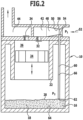
- a first embodiment of a reciprocating compressor for refrigerants according to the invention comprises a crankcase 10 in which a crank drive 12 is provided and which forms a collecting space 14 for lubricant 16, for example oil, which collects in the collecting space 14 during the lubrication of the reciprocating compressor and forms a lubricant bath 18, the surface level 20 of which varies depending on the amount of lubricant 16 in the lubricant bath 18.
- a crankcase 10 in which a crank drive 12 is provided and which forms a collecting space 14 for lubricant 16, for example oil, which collects in the collecting space 14 during the lubrication of the reciprocating compressor and forms a lubricant bath 18, the surface level 20 of which varies depending on the amount of lubricant 16 in the lubricant bath 18.
- a cylinder housing 22 is connected to the crankcase 10, in which a reciprocating piston 24, driven by the crank drive 12, can be moved up and down, whereby a cylinder chamber 26 is available for compressing refrigerant.
- the cylinder chamber 26 is closed off on its side opposite the crank drive 12 by a valve plate designated as a whole by 30, in which at least one inlet valve 32 and at least one outlet valve 34 are provided per cylinder chamber 26.
- a cylinder head 40 which extends over the valve plate 30 and in which a suction gas guide 42 extending to the inlet valve 32 and a pressure gas guide 44 leading away from the outlet valve 34 are provided, wherein the suction gas guide 42 is designed as a channel 48 leading from a suction gas connection 46 to the inlet valve 32 and, for example, running predominantly directly above the valve plate 30.
- refrigerant to be compressed is supplied to the inlet valve 32 in the valve plate 30 via the suction gas guide 42 in the cylinder head 40, namely when the reciprocating piston 24 performs a suction movement, or the refrigerant in the suction gas guide 42 remains essentially without flow, namely when the reciprocating piston 24 performs a compression movement and compresses the refrigerant in the cylinder 26 and finally expels it via the outlet valve 34 into the pressure gas guide 44.
- the suction gas guide 42 in the first embodiment is provided with a nozzle 50 in which an acceleration of a suction gas flow 52 takes place before reaching the inlet valve 32.
- an outlet opening 56 of a lubricant suction channel designated as a whole by 60, is provided, the inlet opening 62 of which is arranged in the collecting chamber 14 of the crankcase 10, specifically at a distance A from a bottom 64 of the collecting chamber 14, so that lubricant 16 can only be sucked in through the inlet opening 62 until, as in Fig. 2 shown, the surface level 20 of the lubricant bath 18 is at the level of the inlet opening 62.
- the lubricant suction channel 60 is designed as a pipe 66 which extends from the region 54 in the nozzle 50 to the inlet opening 62 and, through the position of the inlet opening 62, defines the position of the surface level 20 of the lubricant bath 18 at which it is just possible to suck in lubricant via the lubricant suction channel 60, while if the surface level 20 drops further, it is no longer possible to suck in lubricant.
- the pressure P1 in the region 54 of the suction gas stream 52 flowing through the nozzle 50 is lower than the pressure P2 in the crankcase 10, in particular in the collecting chamber 14, it is possible to suck lubricant out of the crankcase 10 via the lubricant suction channel 60 as long as the surface level 20 is higher than the inlet opening 62 and until the surface level 20 is at the level of the inlet opening 62 of the lubricant suction channel 60.
- the lubricant sucked into the nozzle 50 is fed by the suction gas flow 52 via the inlet valve 32 to the cylinder chamber 26 and is expelled from there again with the compressed refrigerant via the outlet valve 34 and thus discharged via the compressed gas guide 44, for example conveyed with the compressed gas to the next refrigerant compressor.
- the lubricant suction channel 60' is not formed by a pipe 66, but is formed in the crankcase 10, for example a wall region 70 thereof, so that the lubricant suction channel 60' runs in the wall region 70 up to the inlet opening 62, also passes through an opening 72 of the valve plate 30 and finally passes through an opening 74 of the nozzle 50, which reaches up to the outlet opening 56 in the nozzle 50.
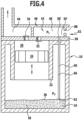
- a reciprocating compressor according to the invention shown in Fig. 4 , those parts which are identical to those of the first or second embodiment are also provided with the same reference numerals, so that reference can be made to the description thereof in full.
- the lubricant suction channel 60 runs in the pipe 66, from the inlet opening 62 to an outlet opening 56', which in this embodiment is located in the area on a side of the valve plate 30 facing the suction gas guide 42, so that the outlet opening 56' is directly adjacent to the channel 48 provided in the cylinder head 40.
- a diaphragm 80 is provided as a throttle device in relation to the suction gas flow 52 upstream of the outlet opening 56', which then, when the reciprocating piston 24 carries out a suction movement while enlarging the cylinder chamber 26, leads to a pressure drop downstream of the diaphragm 80, so that the static pressure P 1 in the area 54' between the diaphragm 80 and the inlet valve 32 drops briefly during the suction movement 24 and thus a static pressure P 1 is established, at least briefly, which is lower than the pressure P 2 in the crankcase 10, in particular in the collecting chamber 14, so that during this time during which the static pressure P 1 is lower than the static pressure P 2 lubricant is then drawn out of the lubricant via the lubricant suction channel 60. the collecting chamber 14 when the surface level 20 is above the inlet opening 62.
- the outlet opening 56 is also located on the valve plate 30, specifically in the region 54' which lies between an adjustable throttle device 90 and the inlet valve 32.
- the throttle device 90 comprises a passage 92, which can be adjusted with regard to its throttling effect for the suction gas flow 52 by means of an adjustable throttle valve 94, for example a throttle valve 94 pivotable about an axis 96, wherein, for example, an actuator 98 is provided.
- an adjustable throttle valve 94 for example a throttle valve 94 pivotable about an axis 96, wherein, for example, an actuator 98 is provided.
- this allows the same effect to be achieved as with the orifice 80, but with the difference that the throttle device 90 can be adjusted in terms of its throttling effect on the suction gas flow 52 by turning the throttle valve 94, so that it is possible to adjust the pressure P 1 , namely in accordance with the suction gas flow 52, so that, for example, during certain partial phases of the suction movement of the reciprocating piston 24, the static pressure P 1 drops to such an extent that it is lower than the static pressure P 2 in the Crankcase 10, in particular in the collecting chamber 14, and thus it is possible to suck lubricant out of the collecting chamber 14 and supply it to the suction gas stream 52 for further transport.
- This solution has the advantage that, due to the adjustability of the throttle valve 94 by means of the actuator 98 according to the operating conditions of the reciprocating compressor, the time periods at which the static pressure P 1 in the channel 48 is lower than the static pressure P 2 in the crankcase 10, in particular in the collecting chamber 14 thereof, can be adjusted in each case in adaptation to the suction gas flow 52.
- the variant of the third embodiment described above thus provides that the setting of the throttle valve 94 remains constant over a large number of working cycles and thus the setting can be made such that at least temporarily the static pressure P1 drops to such an extent that lubricant 16 is sucked in via the lubricant suction channel 60.
- throttle valve 94 dynamically, i.e., for example, to adjust the throttle valve 94 to a specific value for throttling the suction gas flow 52 during each working cycle in order to reduce the static pressure P1 in the region 54' for a specific period of time.
Landscapes
- Engineering & Computer Science (AREA)
- Mechanical Engineering (AREA)
- General Engineering & Computer Science (AREA)
- Compressor (AREA)
- Compressors, Vaccum Pumps And Other Relevant Systems (AREA)
Description
- Die Erfindung betrifft einen Kältemittelkreislauf mit einen Hubkolbenverdichter, umfassend ein Kurbelgehäuse, in welchem ein Sammelraum für Schmiermittel angeordnet ist, ein Zylindergehäuse, in welchem mindestens ein Hubkolben oszillierend bewegbar ist, eine das Zylindergehäuse abschließende Ventilplatte, in welcher mindestens ein Einlassventil und ein Auslassventil angeordnet sind und einen Zylinderkopf, in welchem eine zum Einlassventil hin verlaufende Sauggasführung und eine von dem Auslassventil wegführende Druckgasführung vorgesehen sind.
- Die
US 4,413,954 offenbart einen Taumelscheibenverdichter, in dessen Zylinderblock doppelt wirkende Kolben vorgesehen sind, die in Zylinderbohrungen bewegbar sind, wobei die Zylinderbohrungen durch Ventilplatten verschlossen sind, in welchen Ausgangsöffnungen vorgesehen sind. - Diese Ansaugöffnungen sind Ölansaugbohrungen zugeordnet, in welchen beim Ansaugen des Kältemittels durch die Ansaugöffnungen ein Druckabfall entsteht, so dass über Ölzufuhrpassagen Ölnebel durch die Lager der Antriebswelle gesaugt wird, der weit oberhalb eines Ölsumpfes in die Ölansaugbohrungen eintritt.
- Die
US 3,713,513 offenbart einen Kältemittelverdichter mit einem Kurbelgehäuse, in dessen Innenraum eine Ansaugkammer angeordnet ist, welcher mit einem Kanal Gas von dem Innenraum des Kurbelgehäuses zugeführt wird. - Dieser Kanal dient dazu, kein Öl sondern nur Gas aus dem Innenraum des Kurbelgehäuses der Ansaugkammer zuzuführen, um zu erreichen, dass der Druck im Kurbelgehäuse geringer ist als in dem Motorraum, so dass Öl oder Schmiermittel, das sich im Motorraum sammelt, in das Kurbelgehäuse strömt.
- Die
DE 1 044 839 offenbart einen Schwingkompressor, bei welchem über ein Kapillarrohr aus einem Ölsumpf Öl einer Saugleitung zugeführt wird, um den Kolben zu schmieren. - Der Ölsumpf bildet sich dabei auf dem Boden der den Schwingkompressor aufnehmenden Kapsel, wobei sich der Ölsumpf aus dem in der Kapsel abscheidenden Öl regeneriert, so dass, im Betrieb ständig Öl in geringen Mengen dem angesaugten Dampf zugeführt wird, um den Kolben im Zylinder zu schmieren.
- Die Offenbarung der
DE 1 044 839 geht somit davon aus, dass der Ölsumpf ständig ausreichend Öl zur Verfügung stellt, das durch das Kapillarrohr abgesaugt wird. - Bei einem Kältemittelkreislauf mit mehreren derartigen Hubkolbenverdichtern besteht, insbesondere dann, wenn diese als Hubkolbenverdichter für eine von mehreren Verdichterstufen in dem Kältemittelkreislauf eingebaut sind, das Problem, dass sich je nach Betriebsbedingungen in dem Kurbelgehäuse eine größere Menge Schmiermittel sammelt als vorgesehen.
- Dies führt dazu, dass entweder die insgesamt erforderliche Schmiermittelmenge höher ist als vorgesehen oder andere Komponenten des Kältemittelkreislaufs, beispielsweise ein nachgeordneter Verdichter, nicht ausreichend Schmiermittel zur Verfügung haben.
- Der Erfindung liegt daher die Aufgabe zugrunde, einen Kältemittelkreislauf mit mehreren Hubkolbenverdichtern der gattungsgemäßen Art derart zu verbessern, dass sich übermäßige Schmiermittelansammlungen vermeiden lassen.
- Diese Aufgabe wird bei einem Kältemittelkreislauf mit mehreren Verdichterstufen, erfindungsgemäß durch die Merkmale des Anspruchs 1 gelöst.
- Der Vorteil der erfindungsgemäßen Lösung ist darin zu sehen, dass durch eine derartige Ausführung die Möglichkeit besteht, Schmiermittel aus dem Sammelraum abzusaugen und dem Sauggas zuzuführen, das dann dieses Schmiermittel durch den Hubkolbenverdichter hindurchfördert und über die Druckgasführung im Kältemittelkreislauf weiterfördert, beispielsweise zum nächstfolgenden Verdichter im Kältemittelkreislauf.
- Damit kann auf einfache und kostengünstige Art und Weise vermieden werden, dass sich in dem Hubkolbenverdichter eine übermäßig große Menge an Schmiermittel ansammelt und somit dadurch die bereits erläuterten Probleme auftreten.
- Hinsichtlich der Einlassöffnung im Sammelraum wurden bislang keine näheren Angaben gemacht.
- Prinzipiell würde die Möglichkeit bestehen, die Einlassöffnung nahe eines Bodens des Sammelraums anzuordnen, so dass damit die Möglichkeit besteht, stets dann, wenn der statische Druck in dem Bereich der Sauggasführung niedriger ist als der statische Druck im Sammelraum, Schmiermittel aus dem Sammelraum abzusaugen.
- Erfindungsgemäß ist die Einlassöffnung im Sammelraum so angeordnet, dass sie eine vorbestimmte Lage eines Oberflächenspiegels eines Schmiermittelbades vorgibt.
- Damit lässt sich bereits durch Anordnung der Lage der Einlassöffnung sicherstellen, dass nicht zuviel Schmiermittel aus dem Sammelraum abgesaugt wird, sondern dass stets im Sammelraum eine für den jeweiligen Hubkolbenverdichter ausreichende Schmiermittelmenge verbleibt.
- Dies ist insbesondere auch dann von Vorteil, wenn der Oberflächenspiegel des Schmiermittelbades unter die Einlassöffnung abfällt, da dann im Fall, dass der statische Druck in dem Bereich der Sauggasführung niedriger ist als der statische Druck im Kurbelgehäuse, kein Ansaugen von Schmiermittel erfolgt, sondern einfach ein Absaugen des ohnehin im Kurbelgehäuse vorliegenden Kältemittels.
- Besonders günstig ist es dabei, wenn die Einlassöffnung des Schmiermittelsaugkanals einen durch Absaugen von Schmiermittel über den Schmiermittelsaugkanal erreichbaren niedrigsten Oberflächenspiegel des Schmiermittelbades vorgibt.
- Hinsichtlich des Verlaufs des Schmiermittelsaugkanals in dem Kurbelgehäuse wurden bislang keine näheren Angaben gemacht.
- So sieht eine vorteilhafte Lösung vor, dass der Schmiermittelsaugkanal zumindest abschnittsweise durch ein in das Kurbelgehäuse hineinragendes Rohr verläuft.
- Vorzugsweise weist dieses Rohr die Einlassöffnung auf, so dass sich durch Positionierung des Rohrs im Kurbelgehäuse auch die Lage der Einlassöffnung definieren lässt.
- Eine andere vorteilhafte Lösung sieht vor, dass der Schmiermittelsaugkanal zumindest abschnittsweise in dem Kurbelgehäuse verläuft, das heißt in eine Wand des Kurbelgehäuses eingeformt ist und somit zumindest für diesen Abschnitt kein zusätzliches Rohr erforderlich ist.
- Ferner lässt sich bei dieser Lösung ebenfalls in einfacher Weise die Lage der Einlassöffnung des Schmiermittelsaugkanals fixieren und somit beispielsweise der durch Absaugen erreichbare minimale Schmiermittelstand festlegen.
- Um den statischen Druck in dem Bereich der Sauggasführung abzusenken, in welchem die Auslassöffnung liegt, ist vorzugsweise vorgesehen, dass die Auslassöffnung des Schmiermittelsaugkanals aufweisende Bereich in einer Engstelle einer Düse liegt.
- Dadurch wird bei durch die Düse strömendem Sauggas in der Engstelle ein statischer Druck erzeugt, der niedriger ist als der übrige Druck im Sauggas und somit lässt sich ein Druckgefälle zwischen dem statischen Druck im Kurbelgehäuse, insbesondere im Sammelraum, und dem statischen Druck in der Engstelle der Düse erreichen, wodurch ein Ansaugen vom Schmiermittel aus dem Sammelraum erfolgt.
- Eine alternative Lösung sieht vor, dass der die Auslassöffnung des Schmiermittelsaugkanals aufweisende Bereich der Sauggasführung in Strömungsrichtung des Sauggasstroms hinter einer Drosselvorrichtung in der Sauggasführung liegt.
- Eine derartige Drosselvorrichtung erlaubt es beispielsweise hinter der Drosselstelle, zumindest zeitweise, den statischen Druck soweit abzusenken, dass ein Druckgefälle zwischen dem Sammelraum im Kurbelgehäuse und dem Bereich der Auslassöffnung in der Sauggasführung eintritt und somit ein Absaugen von Schmiermittel aus dem Sammelraum erfolgt.
- Dabei ließe sich beispielsweise die Drosselvorrichtung als ständig wirksame Drosselstelle, beispielsweise durch eine sehr kostengünstige Blende, realisieren, die allerdings eine konstante Drosselwirkung entfaltet.
- Eine andere vorteilhafte Lösung sieht vor, dass eine einstellbare Drosselvorrichtung vorgesehen ist, welche die Möglichkeit eröffnet, beispielsweise je nach Größe des Sauggasstroms, die Drosselwirkung und somit auch den statischen Druck in dem Bereich zwischen der Drosselstelle und dem Einlassventil einzustellen.
- Dabei kann die einstellbare Drosselvorrichtung statisch einstellbar sein, das heißt über eine Vielzahl von Arbeitszyklen hinweg eine gleich bleibende Einstellung aufweisen.
- Eine andere, die Verdichterleistung möglichst wenig beeinträchtigende Lösung sieht vor, dass die einstellbare Drosselvorrichtung zwischen im Wesentlichen drosselfreien zeitlichen Intervallen und drosselwirksamen zeitlichen Intervallen wechselt.
- Dabei können die drosselwirksamen zeitlichen Intervalle sich über weniger als einen Arbeitszyklus des Hubkolbenverdichters oder über mehrere Arbeitszyklen ausdehnen.
- Vorzugsweise dehnen sich die drosselfreien Intervalle über mehrere Arbeitszyklen aus, um die Verdichterleistung möglichst wenig zu beeinträchtigen.
- Weitere Merkmale und Vorteile der Erfindung sind Gegenstand der nachfolgenden Beschreibung sowie der zeichnerischen Darstellung einiger Ausführungsbeispiele.
- In der Zeichnung zeigen:
- Fig. 1
- eine schematische Schnittansicht durch ein ersten Ausführungsbeispiel bei einer übermäßig großen Schmiermittelmenge in einem Sammelraum des Kurbelgehäuses;
- Fig. 2
- einen Schnitt ähnlich
Fig. 1 beim ersten Ausführungsbeispiel bei einer durch Schmiermittelabsaugung reduzierten und definierten Schmiermittelmenge; - Fig. 3
- einen Schnitt ähnlich
Fig. 1 durch ein zweites Ausführungsbeispiel; - Fig. 4
- einen Schnitt ähnlich
Fig. 1 durch ein drittes Ausführungsbeispiel und - Fig. 5
- einen Schnitt ähnlich
Fig. 1 durch ein viertes Ausführungsbeispiel. - Ein erstes Ausführungsbeispiel eines erfindungsgemäßen Hubkolbenverdichters für Kältemittel, dargestellt in
Fig. 1 und2 , umfasst ein Kurbelgehäuse 10, in welchem ein Kurbelantrieb 12 vorgesehen ist und welches einen Sammelraum 14 für Schmiermittel 16, beispielsweise Öl, bildet, das sich in dem Sammelraum 14 bei der Schmierung des Hubkolbenverdichters sammelt und ein Schmiermittelbad 18 bildet, dessen Oberflächenspiegel 20 je nach Menge des Schmiermittels 16 im Schmiermittelbad 18 variiert. - Mit dem Kurbelgehäuse 10 ist ferner ein Zylindergehäuse 22 verbunden, in welchem ein Hubkolben 24, angetrieben durch den Kurbelantrieb 12 auf und ab bewegbar ist, wobei eine Zylinderkammer 26 zum Verdichten von Kältemittel zur Verfügung steht.
- Die Zylinderkammer 26 ist auf ihrer dem Kurbelantrieb 12 gegenüberliegenden Seite durch eine als Ganzes mit 30 bezeichnete Ventilplatte abgeschlossen, in welcher pro Zylinderkammer 26 mindestens ein Einlassventil 32 sowie mindestens ein Auslassventil 34 vorgesehen sind.
- Auf einer der Zylinderkammer 26 gegenüberliegenden Seite der Ventilplatte 30 ist außerdem ein die Ventilplatte 30 übergreifender Zylinderkopf 40 vorgesehen, in welchem eine zum Einlassventil 32 reichende Sauggasführung 42 und eine vom Auslassventil 34 wegführende Druckgasführung 44 vorgesehen sind, wobei die Sauggasführung 42 als von einem Sauggasanschluss 46 zum Einlassventil 32 führender und beispielsweise überwiegend unmittelbar über der Ventilplatte 30 verlaufender Kanal 48 ausgebildet ist.
- Je nach Arbeitszyklus des Hubkolbens 24 wird über die Sauggasführung 42 im Zylinderkopf 40 dem Einlassventil 32 in der Ventilplatte 30 zu verdichtendes Kältemittel zugeführt, nämlich dann, wenn der Hubkolben 24 eine Saugbewegung durchführt, oder das Kältemittel in der Sauggasführung 42 bleibt im Wesentlichen strömungslos, nämlich dann, wenn der Hubkolben 24 eine Kompressionsbewegung durchführt und das Kältemittel in dem Zylinder 26 komprimiert und schließlich über das Auslassventil 34 in die Druckgasführung 44 ausstößt.
- Beim Betrieb eines derartigen Hubkolbenverdichters in einem komplexen System mit einem Kältemittelkreislauf, insbesondere mit mehreren hintereinanderliegend angeordneten Verdichtern, besteht die Gefahr, dass sich in dem Sammelraum 14 desselben eine übermäßig große Menge Schmiermittel 16 ansammelt und somit in anderen Komponenten des Systems gegebenenfalls zu wenig Schmiermittel zur Verfügung steht oder in dem System mit einer unnötig großen Menge an Schmiermittel gearbeitet werden muss, um bei einer derartigen Ansammlung von Schmiermitteln in einem Hubkolbenverdichter einen strömungsfreien Betrieb zu gewährleisten.
- Zur Vermeidung dieses Problems ist die Sauggasführung 42 bei dem ersten Ausführungsbeispiel mit einer Düse 50 versehen, in welcher eine Beschleunigung eines Sauggasstroms 52 vor Erreichen des Einlassventils 32 erfolgt.
- In der Düse 50 tritt aufgrund der Beschleunigung des Sauggasstroms 52 ein Bereich 54 reduzierten Drucks auf, in welchem ein Druck P1 erreichbar ist, der unterhalb eines Drucks P2 in dem Kurbelgehäuse 10 ist.
- In dem Bereich 54 ist eine Auslassöffnung 56 eines als Ganzes mit 60 bezeichneten Schmiermittelsaugkanals vorgesehen, dessen Einlassöffnung 62 im Sammelraum 14 des Kurbelgehäuses 10 angeordnet ist, und zwar in einem Abstand A von einem Boden 64 des Sammelraums 14, so dass durch die Einlassöffnung 62 nur so lange Schmiermittel 16 angesaugt werden kann, bis, wie in
Fig. 2 dargestellt, der Oberflächenspiegel 20 des Schmiermittelbads 18 in Höhe der Einlassöffnung 62 steht. - Vorzugsweise ist dabei der Schmiermittelsaugkanal 60 als Rohr 66 ausgebildet, welches von dem Bereich 54 in der Düse 50 bis zur Einlassöffnung 62 reicht und durch die Lage der Einlassöffnung 62 die Lage des Oberflächenspiegels 20 des Schmiermittelbads 18 definiert, bei welcher gerade noch ein Ansaugen von Schmiermittel über den Schmiermittelsaugkanal 60 möglich ist, während bei weiterem Absinken des Oberflächenspiegels 20 kein Ansaugen von Schmiermittel mehr möglich ist.
- Dadurch, dass bei die Düse 50 durchströmendem Sauggasstrom 52 in dem Bereich 54 der Druck P1 niedriger ist als der Druck P2 im Kurbelgehäuse 10, insbesondere im Sammelraum 14, besteht die Möglichkeit, Schmiermittel über den Schmiermittelsaugkanal 60 aus dem Kurbelgehäuse 10 so lange abzusaugen, solange der Oberflächenspiegel 20 höher als die Einlassöffnung 62 steht und solange bis der Oberflächenspiegel 20 in Höhe der Einlassöffnung 62 des Schmiermittelsaugkanals 60 steht.
- Das in die Düse 50 eingesaugte Schmiermittel wird durch den Sauggasstrom 52 über das Einlassventil 32 der Zylinderkammer 26 zugeführt und von dieser wieder mit dem verdichteten Kältemittel über das Auslassventil 34 ausgestoßen und somit über die Druckgasführung 44 abgeführt, beispielsweise mit dem Druckgas zum nächstfolgenden Kältemittelverdichter gefördert.
- Bei einem zweiten Ausführungsbeispiel eines erfindungsgemäßen Hubkolbenverdichters, dargestellt in
Fig. 3 , sind all diejenigen Teile, die mit denen des ersten Ausführungsbeispiels identisch sind, mit denselben Bezugszeichen versehen, so dass hinsichtlich deren Beschreibung vollinhaltlich auf die Ausführungen zum ersten Ausführungsbeispiel verwiesen werden kann. - Im Gegensatz zum ersten Ausführungsbeispiel ist der Schmiermittelsaugkanal 60' nicht durch ein Rohr 66 gebildet, sondern in das Kurbelgehäuse 10, beispielsweise einen Wandbereich 70 desselben eingeformt, so dass der Schmiermittelsaugkanal 60' in dem Wandbereich 70 bis zur Einlassöffnung 62 verläuft, außerdem einen Durchbruch 72 der Ventilplatte 30 durchsetzt und schließlich noch einen Durchbruch 74 der Düse 50 durchsetzt, welcher bis zur Auslassöffnung 56 in der Düse 50 reicht.
- Bei einem dritten Ausführungsbeispiel eines erfindungsgemäßen Hubkolbenverdichters, dargestellt in
Fig. 4 , sind ebenfalls diejenigen Teile, die mit denen des ersten oder zweiten Ausführungsbeispiels identisch sind, mit denselben Bezugszeichen versehen, so dass auf die Beschreibung derselben vollinhaltlich Bezug genommen werden kann. - Bei dem dritten Ausführungsbeispiel verläuft der Schmiermittelsaugkanal 60 in dem Rohr 66, und zwar von der Einlassöffnung 62 bis zu einer Auslassöffnung 56', die bei diesem Ausführungsbeispiel im Bereich auf einer der Sauggasführung 42 zugewandten Seite der Ventilplatte 30 liegt, so dass die Auslassöffnung 56' unmittelbar an den im Zylinderkopf 40 vorgesehenen Kanal 48 angrenzt.
- Um im Kanal 48 im Bereich der Auslassöffnung 56' einen statischen Druck P1 zu erzeugen, der niedriger ist als der statische Druck P2 im Kurbelgehäuse 10, insbesondere im Sammelraum 14, ist bezogen auf den Sauggasstrom 52 stromaufwärts der Auslassöffnung 56' als Drosselvorrichtung eine Blende 80 vorgesehen, die dann, wenn der Hubkolben 24 eine Ansaugbewegung unter Vergrößerung der Zylinderkammer 26 durchführt, zu einem Druckabfall stromabwärts der Blende 80 führt, so dass der statische Druck P1 in dem Bereich 54' zwischen der Blende 80 und dem Einlassventil 32 während der Ansaugbewegung 24 kurzfristig abfällt und sich somit ein statischer Druck P1 zumindest kurzzeitig einstellt, der niedriger ist als der Druck P2 in dem Kurbelgehäuse 10, insbesondere im Sammelraum 14, so dass während dieser Zeit während der der statische Druck P1 niedriger ist als der statische Druck P2 Schmiermittel über den Schmiermittelsaugkanal 60 dann aus dem Sammelraum 14 abgesaugt wird, wenn der Oberflächenspiegel 20 über der Einlassöffnung 62 steht.
- In all den Fällen, in denen dann der statische Druck P1 in den Kanal 48 auf einem gleich hohen Druck liegt, wie der statische Druck P2 im Kurbelgehäuse 10 oder höher, erfolgt kein Ansaugen von Schmiermittel 16 aus dem Sammelraum 14, was jedoch keinerlei Nachteil darstellt, da bereits ein sich in jeden Arbeitszyklus wiederholendes temporäres Ansaugen von Schmiermittel durch den Schmiermittelsaugkanal 60 in den Bereich 54 ausreicht, um im zeitlichen Mittel den Oberflächenspiegel 20 des Schmiermittelbades 18 im Bereich der Einlassöffnung 62 zu halten.
- Bei einem vierten Ausführungsbeispiel eines erfindungsgemäßen Hubkolbenverdichters, dargestellt in
Fig. 5 , sind ebenfalls diejenigen Teile, die mit einem der voranstehenden Ausführungsbeispiele identisch sind, mit denselben Bezugszeichen versehen, so dass hinsichtlich der Beschreibung derselben vollinhaltlich auf die Ausführungen zu den voranstehenden Ausführungsbeispielen Bezug genommen werden kann. - Auch bei diesem Ausführungsbeispiel liegt die Auslassöffnung 56 an der Ventilplatte 30 und zwar in dem Bereich 54', welcher zwischen einer einstellbaren Drosselvorrichtung 90 und dem Einlassventil 32 liegt.
- Die Drosselvorrichtung 90 umfasst dabei einen Durchlass 92, welcher mit einer einstellbaren Drosselklappe 94, beispielsweise einer um eine Achse 96 schwenkbaren Drosselklappe 94, hinsichtlich seiner Drosselwirkung für den Sauggasstrom 52 verstellbar ist, wobei beispielsweise ein Stellantrieb 98 vorgesehen ist.
- Damit lässt sich im Prinzip dieselbe Wirkung erzielen, wie mit der Blende 80, allerdings mit dem Unterschied, dass die Drosselvorrichtung 90 durch Drehen der Drosselklappe 94 hinsichtlich ihrer Drosselwirkung auf den Sauggasstrom 52 einstellbar ist, so dass die Möglichkeit besteht, den Druck P1 einzustellen, und zwar entsprechend dem Sauggasstrom 52, so dass beispielsweise bei bestimmten Teilphasen der Ansaugbewegung des Hubkolbens 24 der statische Druck P1 soweit abfällt, dass dieser niedriger liegt als der statische Druck P2 im Kurbelgehäuse 10, insbesondere im Sammelraum 14 und somit die Möglichkeit besteht, Schmiermittel aus dem Sammelraum 14 abzusaugen und dem Sauggasstrom 52 zum Weitertransport zuzuführen.
- Diese Lösung hat den Vorteil, dass durch die Einstellbarkeit der Drosselklappe 94 mittels des Stellantriebs 98 entsprechend den Betriebsbedingungen des Hubkolbenverdichters die Zeiträume, zu denen der statische Druck P1 im Kanal 48 niedriger ist als der statische Druck P2 im Kurbelgehäuse 10, insbesondere im Sammelraum 14 desselben, jeweils in Anpassung an den Sauggasstrom 52 einstellbar ist.
- Die vorstehend beschriebene Variante des dritten Ausführungsbeispiels sieht somit vor, dass die Einstellung der Drosselklappe 94 über eine Vielzahl von Arbeitszyklen konstant bleibt und somit die Einstellung so erfolgen kann, dass zumindest zeitweise der statische Druck P1 so weit abfällt, dass eine Ansaugung von Schmiermittel 16 über den Schmiermittelsaugkanal 60 erfolgt.
- Alternativ ist es aber auch denkbar, die Einstellung der Drosselklappe 94 dynamisch vorzunehmen, das heißt beispielsweise im Verlauf eines jeden Arbeitszyklus die Drosselklappe 94 auf einen bestimmten Wert der Drosselung des Sauggasstroms 52 einzustellen, um für einen bestimmten Zeitraum den statischen Druck P1 im Bereich 54' abzusenken.
- Es ist aber auch denkbar, die Drosselklappe 94 nicht bei jedem Arbeitszyklus zur Drosselung des Sauggasstroms 52 einzusetzen, sondern beispielsweise nur während eines oder weniger Arbeitszyklen den Sauggasstrom 52 mit der Drosselklappe 94 zu drosseln und dann für eine Vielzahl von Arbeitszyklen die Drosselklappe 94 so anzusteuern, dass keine Drosselung mehr erfolgt, so dass während vielen Arbeitszyklen entsprechenden Zeiträumen keinerlei Drosselung des Sauggasstroms 52 durch die Drosselklappe 94 erfolgt, um die Verdichterleistung nicht zu beeinträchtigen, und nur unter Inkaufnahme einer kurzfristigen Beeinträchtigung der Verdichterleistung eine Drosselung des Sauggasstroms 52 mit der Drosselklappe 94 erfolgt, um Schmiermittel über den Schmiermittelsaugkanal 60 aus dem Sammelraum 14 abzusaugen, während nachfolgend wieder für einen nennenswert langen Zeitraum die Drosselklappe 94 geöffnet wird, um wiederum die volle Verdichterleistung zur Verfügung zuhaben.
Claims (10)
- Kältemittelkreislauf mit mehreren Verdichterstufen, wobei eine Verdichterstufe als Hubkolbenverdichter in den Kältemittelkreislauf eingebaut ist und folgendes umfasst, ein Kurbelgehäuse (10), in welchem Sammelraum (14) für Schmiermittel (16) angeordnet ist, ein Zylindergehäuse (22) in welchem mindestens ein Hubkolben (24) oszillierend bewegbar ist, eine das Zylindergehäuse (22) abschließende Ventilplatte (30), in welcher mindestens ein Einlassventil (32) und ein Auslassventil (34) angeordnet sind, und einen Zylinderkopf (40) in welchem eine zum Einlassventil (32) hin verlaufende Sauggasführung (42) und eine vom Auslassventil (34) wegführende Druckgasführung (44) vorgesehen sind,
wobei ein Schmiermittelsaugkanal (60) vorgesehen ist, der eine dem Sammelraum (14) zugeordnete Einlassöffnung (62) und eine der Sauggasführung (42) zugeordnete Auslassöffnung (56) aufweist, wobei die Einlassöffnung (62) im Sammelraum (14) so angeordnet ist, dass sie eine vorbestimmte Lage eines Oberflächenspiegels (20) eines Schmiermittelbades (18) vorgibt, und wobei die Auslassöffnung (56) in einem Bereich (54) der Sauggasführung (42) liegt, in welchem zumindest zeitweilig ein statischer Druck (P1) vorherrscht, der niedriger als ein statischer Druck (P2) im Sammelraum (14) für Schmiermittel (16) ist, so dass Schmiermittel aus dem Sammelraum (14) abgesaugt und dem Sauggas zugeführt wird, das dann dieses Schmiermittel durch den Hubkolbenverdichter hindurchfördert und über eine Druckgasführung im Kältemittelkreislauf zum nächstfolgenden Verdichter im Kältemittelkreislauf weiterfördert. - Kältemittelkreislauf nach Anspruch 1, dadurch gekennzeichnet, dass die Einlassöffnung (62) des Schmiermittelsaugkanals (60) einen durch Absaugen von Schmiermittel (16) über den Schmiermittelsaugkanal (60) erreichbaren niedrigsten Oberflächenspiegel (20) des Schmiermittelbades (18) vorgibt.
- Kältemittelkreislauf nach einem der voranstehenden Ansprüche, dadurch gekennzeichnet, dass der Schmiermittelsaugkanal (60) zumindest abschnittsweise durch ein in das Kurbelgehäuse (10) hineinragendes Rohr (66) verläuft.
- Kältemittelkreislauf nach Anspruch 3, dadurch gekennzeichnet, dass das Rohr (66) die Einlassöffnung (62) aufweist.
- Kältemittelkreislauf nach einem der voranstehenden Ansprüche, dadurch gekennzeichnet, dass der Schmiermittelsaugkanal (60) zumindest abschnittsweise in dem Kurbelgehäuse (10) verläuft.
- Kältemittelkreislauf nach einem der voranstehenden Ansprüche, dadurch gekennzeichnet, dass der die Auslassöffnung (56) des Schmiermittelsaugkanals (60) aufweisende Bereich (54) in einer Engstelle einer Düse (50) liegt.
- Kältemittelkreislauf nach einem der Ansprüche 1 bis 5, dadurch gekennzeichnet, dass der die Auslassöffnung (56) des Schmiermittelsaugkanals (60) aufweisende Bereich (54) der Sauggasführung (42) in Strömungsrichtung des Sauggasstroms (52) hinter einer Drosselvorrichtung (80, 90) in der Sauggasführung (42) liegt.
- Kältemittelkreislauf nach Anspruch 7, dadurch gekennzeichnet, dass die Drosselvorrichtung als Blende (80) ausgebildet ist.
- Kältemittelkreislauf nach Anspruch 7, dadurch gekennzeichnet, dass die Drosselvorrichtung eine einstellbare Drosselvorrichtung (90) ist.
- Kältemittelkreislauf nach Anspruch 9, dadurch gekennzeichnet, dass die einstellbare Drosselvorrichtung (90) zwischen im Wesentlichen drosselfreien zeitlichen Intervallen und drosselwirksamen zeitlichen Intervallen wechselt.
Applications Claiming Priority (3)
| Application Number | Priority Date | Filing Date | Title |
|---|---|---|---|
| DE102008004569A DE102008004569A1 (de) | 2008-01-10 | 2008-01-10 | Hubkolbenverdichter |
| PCT/EP2008/068357 WO2009087071A1 (de) | 2008-01-10 | 2008-12-30 | Hubkolbenverdichter |
| EP08869359.3A EP2229532B1 (de) | 2008-01-10 | 2008-12-30 | Hubkolbenverdichter |
Related Parent Applications (1)
| Application Number | Title | Priority Date | Filing Date |
|---|---|---|---|
| EP08869359.3A Division EP2229532B1 (de) | 2008-01-10 | 2008-12-30 | Hubkolbenverdichter |
Publications (2)
| Publication Number | Publication Date |
|---|---|
| EP3557056A1 EP3557056A1 (de) | 2019-10-23 |
| EP3557056B1 true EP3557056B1 (de) | 2024-11-06 |
Family
ID=40461769
Family Applications (2)
| Application Number | Title | Priority Date | Filing Date |
|---|---|---|---|
| EP19176434.9A Active EP3557056B1 (de) | 2008-01-10 | 2008-12-30 | Kältemittelkreislauf mit mehreren verdichterstufen |
| EP08869359.3A Active EP2229532B1 (de) | 2008-01-10 | 2008-12-30 | Hubkolbenverdichter |
Family Applications After (1)
| Application Number | Title | Priority Date | Filing Date |
|---|---|---|---|
| EP08869359.3A Active EP2229532B1 (de) | 2008-01-10 | 2008-12-30 | Hubkolbenverdichter |
Country Status (6)
| Country | Link |
|---|---|
| US (1) | US8690545B2 (de) |
| EP (2) | EP3557056B1 (de) |
| CN (1) | CN101910630B (de) |
| DE (1) | DE102008004569A1 (de) |
| TR (1) | TR201909111T4 (de) |
| WO (1) | WO2009087071A1 (de) |
Families Citing this family (9)
| Publication number | Priority date | Publication date | Assignee | Title |
|---|---|---|---|---|
| DE102013203268A1 (de) * | 2013-02-27 | 2014-08-28 | Bitzer Kühlmaschinenbau Gmbh | Kältemittelverdichteranlage |
| FR3009896A1 (fr) | 2013-08-20 | 2015-02-27 | Commissariat Energie Atomique | Electrolyte liquide pour accumulateur au lithium-ion, accumulateur au lithium-ion et procede de charge d'un accumulateur lithium-ion |
| DE102015103730A1 (de) * | 2015-03-13 | 2016-09-15 | Bitzer Kühlmaschinenbau Gmbh | Kältemittelverdichteranlage |
| JP2017198406A (ja) * | 2016-04-28 | 2017-11-02 | 株式会社デンソー | 減圧装置および冷凍サイクル装置 |
| US12092373B2 (en) * | 2018-10-12 | 2024-09-17 | Officine Mario Dorin S.P.A. | Reciprocating-type compressor for refrigeration and/or conditioning and/or heat pump system |
| GB2587663B (en) * | 2019-10-04 | 2021-11-03 | Ernest H Hill Ltd | Improvements to pumps and compressors |
| NL2031315B1 (en) * | 2022-03-17 | 2023-09-29 | Gea Refrigeration Netherlands N V | A compressor assembly |
| CN115182870B (zh) * | 2022-07-18 | 2024-01-16 | 西南石油大学 | 一种用于往复式压缩缸的流线型气道结构 |
| KR102825391B1 (ko) * | 2022-11-04 | 2025-07-02 | 노상인 | 낮은 소음과 향상된 윤활성을 가지는 압축기 |
Family Cites Families (25)
| Publication number | Priority date | Publication date | Assignee | Title |
|---|---|---|---|---|
| GB237323A (en) * | 1924-03-28 | 1925-07-28 | Henry Selby Hele Shaw | Improvements in rotary air compressors |
| US1795445A (en) * | 1927-11-21 | 1931-03-10 | Walter G E Rolaff | Reciprocating compressor |
| US2023435A (en) * | 1928-07-06 | 1935-12-10 | Servel Inc | Refrigeration |
| US2054097A (en) * | 1932-05-31 | 1936-09-15 | James B Replogle | Harmonic compressor |
| US2128065A (en) * | 1935-09-04 | 1938-08-23 | Westinghouse Air Brake Co | Compressor lubricator |
| US2155051A (en) * | 1937-06-03 | 1939-04-18 | Sulzer Ag | Apparatus for the compression of gases |
| US2150487A (en) * | 1938-06-04 | 1939-03-14 | Carrier Corp | Compressor apparatus |
| US2233168A (en) * | 1939-04-19 | 1941-02-25 | Gen Electric | Compressor |
| US2629538A (en) * | 1948-05-06 | 1953-02-24 | James B Replogle | Oscillating electrical compressor |
| DE1044839B (de) * | 1956-01-23 | 1958-11-27 | Licentia Gmbh | Anordnung zur Schmierung eines gekapselten Schwingkompressors, insbesondere fuer Kaeltemaschinen |
| DE1972144U (de) * | 1967-03-31 | 1967-11-09 | Otto Boge Fa | Vakuumpumpe. |
| GB1244105A (en) * | 1969-02-04 | 1971-08-25 | Bitzer Kuehlmaschb G M B H | Reciprocating piston compressors |
| US3746477A (en) * | 1970-05-01 | 1973-07-17 | Tokyo Shibaura Electric Co | Rotary compressor |
| US3713513A (en) * | 1971-06-10 | 1973-01-30 | Fedders Corp | Crankcase evacuation and oil return system |
| HK40578A (en) * | 1972-10-04 | 1978-07-21 | Mitchell Co John E | Refrigeration compressor |
| DE2402029B2 (de) * | 1974-01-17 | 1980-04-24 | 1000 Berlin | Schmiervorrichtung für Rotationskolbenverdichter |
| US4127363A (en) * | 1976-12-16 | 1978-11-28 | Kabushiki Kaisha Toyoda Jidoshokki Seisakusho | Swash-plate type compressor |
| JPS5732084A (en) * | 1980-07-31 | 1982-02-20 | Diesel Kiki Co Ltd | Swash plate type compressor |
| US4613284A (en) * | 1985-09-03 | 1986-09-23 | Iosif Baumberg | Apparatus for elevating liquids including a Venturi pipe and a liquid delay element |
| DE4134184A1 (de) * | 1991-10-16 | 1993-04-22 | Bosch Gmbh Robert | Verstellbare hydrostatische pumpe |
| US5190121A (en) * | 1991-10-31 | 1993-03-02 | General Motors Corporation | Two phase compressor lubrication |
| DE4320541A1 (de) | 1993-06-21 | 1994-12-22 | Wagner Gmbh J | Vorrichtung zum Verspritzen von Spritzgut unter hohem Druck |
| US5347821A (en) * | 1993-07-23 | 1994-09-20 | American Standard Inc. | Apparatus and method of oil charge loss protection for compressors |
| DE4445957A1 (de) * | 1994-12-22 | 1996-06-27 | Abb Management Ag | Verfahren und Vorrichtung zur Eigenschmierung der Wälzlager von Turbomaschinen |
| DE10358471A1 (de) * | 2003-11-17 | 2005-06-23 | Bitzer Kühlmaschinenbau Gmbh | Kältemittelverdichter für Kraftfahrzeuge |
-
2008
- 2008-01-10 DE DE102008004569A patent/DE102008004569A1/de not_active Ceased
- 2008-12-30 WO PCT/EP2008/068357 patent/WO2009087071A1/de not_active Ceased
- 2008-12-30 EP EP19176434.9A patent/EP3557056B1/de active Active
- 2008-12-30 EP EP08869359.3A patent/EP2229532B1/de active Active
- 2008-12-30 CN CN200880124472.0A patent/CN101910630B/zh active Active
-
2009
- 2009-12-30 TR TR2019/09111T patent/TR201909111T4/tr unknown
-
2010
- 2010-07-07 US US12/831,508 patent/US8690545B2/en active Active
Also Published As
| Publication number | Publication date |
|---|---|
| US20110005266A1 (en) | 2011-01-13 |
| EP3557056A1 (de) | 2019-10-23 |
| EP2229532A1 (de) | 2010-09-22 |
| EP2229532B1 (de) | 2019-05-29 |
| US8690545B2 (en) | 2014-04-08 |
| CN101910630A (zh) | 2010-12-08 |
| TR201909111T4 (tr) | 2019-07-22 |
| WO2009087071A1 (de) | 2009-07-16 |
| CN101910630B (zh) | 2014-01-01 |
| DE102008004569A1 (de) | 2009-07-16 |
Similar Documents
| Publication | Publication Date | Title |
|---|---|---|
| EP3557056B1 (de) | Kältemittelkreislauf mit mehreren verdichterstufen | |
| EP2064446B1 (de) | Verdichter mit gasdruckgelagertem kolben | |
| DE3438262C2 (de) | ||
| DE4008882C2 (de) | ||
| DE3718651A1 (de) | Stroemungsteiler | |
| DE102014118266B3 (de) | Kompressorvorrichtung mit separatem Luftentölelement | |
| EP0758054A1 (de) | Schmiersystem für Schraubenverdichtern | |
| DE2650935A1 (de) | Gekapselte kaeltemaschine | |
| DE68906511T2 (de) | In-line-filtereinrichtung fuer druckluft. | |
| EP3657017B1 (de) | Kältemittelverdichter | |
| EP3209883B1 (de) | Saugschalldämpfer für einen hermetisch gekapselten kältemittelverdichter | |
| EP2961985B1 (de) | Kältemittelverdichteranlage | |
| DE102015122443B4 (de) | Kältemittelverdichteranlage | |
| DE69303447T2 (de) | Vakuumpumpgerät | |
| EP3377764B1 (de) | Pneumatisch gesteuertes entwässerungsventil | |
| AT525559B1 (de) | Kolbenkompressor mit reduziertem Kurbelgehäuseinnendruck | |
| WO2022167502A1 (de) | Verdichter, insbesondere kältemittelverdichter, kältemaschine, sowie verfahren zur herstellung eines verdichters | |
| DE102008025322B4 (de) | Kältemittelverdichter | |
| DE898918C (de) | Verfahren und Vorrichtung zur Schmierung, Filterung und Geraeuschdaempfung bei Kaeltemaschinen | |
| DE9305554U1 (de) | Zweifach-Verdrängerpumpe | |
| DE2650936B1 (de) | Gekapselte Kaeltemaschine | |
| DE102016217440A1 (de) | Abscheideeinrichtung | |
| DE919593C (de) | Schmiermittelzufuehrung fuer Kaeltemaschinen | |
| DE60033049T2 (de) | Kühlkreislauf | |
| DE10142540A1 (de) | Taumelscheibenkompressor |
Legal Events
| Date | Code | Title | Description |
|---|---|---|---|
| PUAI | Public reference made under article 153(3) epc to a published international application that has entered the european phase |
Free format text: ORIGINAL CODE: 0009012 |
|
| STAA | Information on the status of an ep patent application or granted ep patent |
Free format text: STATUS: THE APPLICATION HAS BEEN PUBLISHED |
|
| AC | Divisional application: reference to earlier application |
Ref document number: 2229532 Country of ref document: EP Kind code of ref document: P |
|
| AK | Designated contracting states |
Kind code of ref document: A1 Designated state(s): AT BE BG CH CY CZ DE DK EE ES FI FR GB GR HR HU IE IS IT LI LT LU LV MC MT NL NO PL PT RO SE SI SK TR |
|
| STAA | Information on the status of an ep patent application or granted ep patent |
Free format text: STATUS: REQUEST FOR EXAMINATION WAS MADE |
|
| 17P | Request for examination filed |
Effective date: 20200319 |
|
| RBV | Designated contracting states (corrected) |
Designated state(s): AT BE BG CH CY CZ DE DK EE ES FI FR GB GR HR HU IE IS IT LI LT LU LV MC MT NL NO PL PT RO SE SI SK TR |
|
| STAA | Information on the status of an ep patent application or granted ep patent |
Free format text: STATUS: EXAMINATION IS IN PROGRESS |
|
| 17Q | First examination report despatched |
Effective date: 20220304 |
|
| P01 | Opt-out of the competence of the unified patent court (upc) registered |
Effective date: 20230517 |
|
| GRAP | Despatch of communication of intention to grant a patent |
Free format text: ORIGINAL CODE: EPIDOSNIGR1 |
|
| STAA | Information on the status of an ep patent application or granted ep patent |
Free format text: STATUS: GRANT OF PATENT IS INTENDED |
|
| RIC1 | Information provided on ipc code assigned before grant |
Ipc: F04B 39/12 20060101ALI20231206BHEP Ipc: F04B 39/02 20060101AFI20231206BHEP |
|
| INTG | Intention to grant announced |
Effective date: 20240104 |
|
| GRAJ | Information related to disapproval of communication of intention to grant by the applicant or resumption of examination proceedings by the epo deleted |
Free format text: ORIGINAL CODE: EPIDOSDIGR1 |
|
| STAA | Information on the status of an ep patent application or granted ep patent |
Free format text: STATUS: EXAMINATION IS IN PROGRESS |
|
| GRAP | Despatch of communication of intention to grant a patent |
Free format text: ORIGINAL CODE: EPIDOSNIGR1 |
|
| STAA | Information on the status of an ep patent application or granted ep patent |
Free format text: STATUS: GRANT OF PATENT IS INTENDED |
|
| INTC | Intention to grant announced (deleted) | ||
| INTG | Intention to grant announced |
Effective date: 20240529 |
|
| GRAS | Grant fee paid |
Free format text: ORIGINAL CODE: EPIDOSNIGR3 |
|
| GRAA | (expected) grant |
Free format text: ORIGINAL CODE: 0009210 |
|
| STAA | Information on the status of an ep patent application or granted ep patent |
Free format text: STATUS: THE PATENT HAS BEEN GRANTED |
|
| AC | Divisional application: reference to earlier application |
Ref document number: 2229532 Country of ref document: EP Kind code of ref document: P |
|
| AK | Designated contracting states |
Kind code of ref document: B1 Designated state(s): AT BE BG CH CY CZ DE DK EE ES FI FR GB GR HR HU IE IS IT LI LT LU LV MC MT NL NO PL PT RO SE SI SK TR |
|
| REG | Reference to a national code |
Ref country code: GB Ref legal event code: FG4D Free format text: NOT ENGLISH |
|
| REG | Reference to a national code |
Ref country code: CH Ref legal event code: EP |
|
| REG | Reference to a national code |
Ref country code: DE Ref legal event code: R096 Ref document number: 502008017275 Country of ref document: DE |
|
| REG | Reference to a national code |
Ref country code: IE Ref legal event code: FG4D Free format text: LANGUAGE OF EP DOCUMENT: GERMAN |
|
| REG | Reference to a national code |
Ref country code: LT Ref legal event code: MG9D |
|
| REG | Reference to a national code |
Ref country code: NL Ref legal event code: MP Effective date: 20241106 |
|
| PG25 | Lapsed in a contracting state [announced via postgrant information from national office to epo] |
Ref country code: HR Free format text: LAPSE BECAUSE OF FAILURE TO SUBMIT A TRANSLATION OF THE DESCRIPTION OR TO PAY THE FEE WITHIN THE PRESCRIBED TIME-LIMIT Effective date: 20241106 Ref country code: IS Free format text: LAPSE BECAUSE OF FAILURE TO SUBMIT A TRANSLATION OF THE DESCRIPTION OR TO PAY THE FEE WITHIN THE PRESCRIBED TIME-LIMIT Effective date: 20250306 Ref country code: PT Free format text: LAPSE BECAUSE OF FAILURE TO SUBMIT A TRANSLATION OF THE DESCRIPTION OR TO PAY THE FEE WITHIN THE PRESCRIBED TIME-LIMIT Effective date: 20250306 |
|
| PG25 | Lapsed in a contracting state [announced via postgrant information from national office to epo] |
Ref country code: FI Free format text: LAPSE BECAUSE OF FAILURE TO SUBMIT A TRANSLATION OF THE DESCRIPTION OR TO PAY THE FEE WITHIN THE PRESCRIBED TIME-LIMIT Effective date: 20241106 Ref country code: NL Free format text: LAPSE BECAUSE OF FAILURE TO SUBMIT A TRANSLATION OF THE DESCRIPTION OR TO PAY THE FEE WITHIN THE PRESCRIBED TIME-LIMIT Effective date: 20241106 |
|
| PG25 | Lapsed in a contracting state [announced via postgrant information from national office to epo] |
Ref country code: BG Free format text: LAPSE BECAUSE OF FAILURE TO SUBMIT A TRANSLATION OF THE DESCRIPTION OR TO PAY THE FEE WITHIN THE PRESCRIBED TIME-LIMIT Effective date: 20241106 |
|
| PG25 | Lapsed in a contracting state [announced via postgrant information from national office to epo] |
Ref country code: ES Free format text: LAPSE BECAUSE OF FAILURE TO SUBMIT A TRANSLATION OF THE DESCRIPTION OR TO PAY THE FEE WITHIN THE PRESCRIBED TIME-LIMIT Effective date: 20241106 |
|
| PG25 | Lapsed in a contracting state [announced via postgrant information from national office to epo] |
Ref country code: NO Free format text: LAPSE BECAUSE OF FAILURE TO SUBMIT A TRANSLATION OF THE DESCRIPTION OR TO PAY THE FEE WITHIN THE PRESCRIBED TIME-LIMIT Effective date: 20250206 |
|
| PG25 | Lapsed in a contracting state [announced via postgrant information from national office to epo] |
Ref country code: GR Free format text: LAPSE BECAUSE OF FAILURE TO SUBMIT A TRANSLATION OF THE DESCRIPTION OR TO PAY THE FEE WITHIN THE PRESCRIBED TIME-LIMIT Effective date: 20250207 Ref country code: LV Free format text: LAPSE BECAUSE OF FAILURE TO SUBMIT A TRANSLATION OF THE DESCRIPTION OR TO PAY THE FEE WITHIN THE PRESCRIBED TIME-LIMIT Effective date: 20241106 |
|
| PG25 | Lapsed in a contracting state [announced via postgrant information from national office to epo] |
Ref country code: PL Free format text: LAPSE BECAUSE OF FAILURE TO SUBMIT A TRANSLATION OF THE DESCRIPTION OR TO PAY THE FEE WITHIN THE PRESCRIBED TIME-LIMIT Effective date: 20241106 |
|
| PG25 | Lapsed in a contracting state [announced via postgrant information from national office to epo] |
Ref country code: DK Free format text: LAPSE BECAUSE OF FAILURE TO SUBMIT A TRANSLATION OF THE DESCRIPTION OR TO PAY THE FEE WITHIN THE PRESCRIBED TIME-LIMIT Effective date: 20241106 |
|
| PG25 | Lapsed in a contracting state [announced via postgrant information from national office to epo] |
Ref country code: EE Free format text: LAPSE BECAUSE OF FAILURE TO SUBMIT A TRANSLATION OF THE DESCRIPTION OR TO PAY THE FEE WITHIN THE PRESCRIBED TIME-LIMIT Effective date: 20241106 |
|
| PG25 | Lapsed in a contracting state [announced via postgrant information from national office to epo] |
Ref country code: RO Free format text: LAPSE BECAUSE OF FAILURE TO SUBMIT A TRANSLATION OF THE DESCRIPTION OR TO PAY THE FEE WITHIN THE PRESCRIBED TIME-LIMIT Effective date: 20241106 |
|
| PG25 | Lapsed in a contracting state [announced via postgrant information from national office to epo] |
Ref country code: SK Free format text: LAPSE BECAUSE OF FAILURE TO SUBMIT A TRANSLATION OF THE DESCRIPTION OR TO PAY THE FEE WITHIN THE PRESCRIBED TIME-LIMIT Effective date: 20241106 |
|
| PG25 | Lapsed in a contracting state [announced via postgrant information from national office to epo] |
Ref country code: CZ Free format text: LAPSE BECAUSE OF FAILURE TO SUBMIT A TRANSLATION OF THE DESCRIPTION OR TO PAY THE FEE WITHIN THE PRESCRIBED TIME-LIMIT Effective date: 20241106 |
|
| REG | Reference to a national code |
Ref country code: CH Ref legal event code: PL |
|
| REG | Reference to a national code |
Ref country code: DE Ref legal event code: R097 Ref document number: 502008017275 Country of ref document: DE |
|
| PG25 | Lapsed in a contracting state [announced via postgrant information from national office to epo] |
Ref country code: LU Free format text: LAPSE BECAUSE OF NON-PAYMENT OF DUE FEES Effective date: 20241230 |
|
| PG25 | Lapsed in a contracting state [announced via postgrant information from national office to epo] |
Ref country code: SE Free format text: LAPSE BECAUSE OF FAILURE TO SUBMIT A TRANSLATION OF THE DESCRIPTION OR TO PAY THE FEE WITHIN THE PRESCRIBED TIME-LIMIT Effective date: 20241106 |
|
| PLBE | No opposition filed within time limit |
Free format text: ORIGINAL CODE: 0009261 |
|
| STAA | Information on the status of an ep patent application or granted ep patent |
Free format text: STATUS: NO OPPOSITION FILED WITHIN TIME LIMIT |
|
| PG25 | Lapsed in a contracting state [announced via postgrant information from national office to epo] |
Ref country code: MC Free format text: LAPSE BECAUSE OF FAILURE TO SUBMIT A TRANSLATION OF THE DESCRIPTION OR TO PAY THE FEE WITHIN THE PRESCRIBED TIME-LIMIT Effective date: 20241106 |
|
| REG | Reference to a national code |
Ref country code: BE Ref legal event code: MM Effective date: 20241231 |
|
| 26N | No opposition filed |
Effective date: 20250807 |
|
| PGFP | Annual fee paid to national office [announced via postgrant information from national office to epo] |
Ref country code: TR Payment date: 20250929 Year of fee payment: 18 Ref country code: IT Payment date: 20250929 Year of fee payment: 18 |
|
| PG25 | Lapsed in a contracting state [announced via postgrant information from national office to epo] |
Ref country code: BE Free format text: LAPSE BECAUSE OF NON-PAYMENT OF DUE FEES Effective date: 20241231 |
|
| PGFP | Annual fee paid to national office [announced via postgrant information from national office to epo] |
Ref country code: FR Payment date: 20250926 Year of fee payment: 18 |
|
| PG25 | Lapsed in a contracting state [announced via postgrant information from national office to epo] |
Ref country code: CH Free format text: LAPSE BECAUSE OF NON-PAYMENT OF DUE FEES Effective date: 20241231 |
|
| PG25 | Lapsed in a contracting state [announced via postgrant information from national office to epo] |
Ref country code: IE Free format text: LAPSE BECAUSE OF NON-PAYMENT OF DUE FEES Effective date: 20241230 |
|
| PGFP | Annual fee paid to national office [announced via postgrant information from national office to epo] |
Ref country code: DE Payment date: 20250926 Year of fee payment: 18 |
|
| PGFP | Annual fee paid to national office [announced via postgrant information from national office to epo] |
Ref country code: GB Payment date: 20251223 Year of fee payment: 18 |
|
| REG | Reference to a national code |
Ref country code: AT Ref legal event code: MM01 Ref document number: 1739595 Country of ref document: AT Kind code of ref document: T Effective date: 20241230 |