EP3556923A1 - Machine à coudre - Google Patents
Machine à coudre Download PDFInfo
- Publication number
- EP3556923A1 EP3556923A1 EP19165705.5A EP19165705A EP3556923A1 EP 3556923 A1 EP3556923 A1 EP 3556923A1 EP 19165705 A EP19165705 A EP 19165705A EP 3556923 A1 EP3556923 A1 EP 3556923A1
- Authority
- EP
- European Patent Office
- Prior art keywords
- cam
- sewing machine
- presser foot
- drive
- cam lever
- Prior art date
- Legal status (The legal status is an assumption and is not a legal conclusion. Google has not performed a legal analysis and makes no representation as to the accuracy of the status listed.)
- Granted
Links
Images


Classifications
-
- D—TEXTILES; PAPER
- D05—SEWING; EMBROIDERING; TUFTING
- D05B—SEWING
- D05B29/00—Pressers; Presser feet
- D05B29/02—Presser-control devices
-
- D—TEXTILES; PAPER
- D05—SEWING; EMBROIDERING; TUFTING
- D05B—SEWING
- D05B29/00—Pressers; Presser feet
- D05B29/06—Presser feet
- D05B29/08—Presser feet comprising relatively-movable parts
Definitions
- the invention relates to a sewing machine.
- Such a sewing machine is known from the EP 2 975 169 B1 and the EP 2 105 526 B1 ,
- the CN 202658372 U discloses a presser foot fan assembly comprising a stepper motor that interacts with other components of the fan assembly via a cam.
- the JP 07-231 991 A discloses a sewing machine with a presser foot drive.
- the EP 2 351 881 A1 discloses a multi-head embroidery machine having a gear for a presser foot of a presser unit.
- the US 2018/0016722 A1 discloses a sewing machine. From the DE-PS 292 059 a pusher foot lifting device for sewing machines is known.
- Object of the present invention is to increase the reliability of a common drive for a pressure-adjusting device on the one hand and a fan device on the other.
- Unfavorable power transmission directions in the power transmission between the cam and the respective Abtast emotions the cam lever can be avoided.
- An undefined release of the cam lever of the cam can be prevented thereby.
- the sensing bodies may be separate components integral with the other cam lever.
- the sensing bodies may be portions of the cam lever itself.
- the cam can have exactly one curve, with which both Abtast emotions cooperate. In this case, the two Abtast endeavor cooperate with different curve sections of the same curve of the cam.
- a simultaneous interaction of the scanning of the cam lever with the cam according to claim 2 can ensure a particularly secure adhesion between the cam lever and the cam.
- "foot lifting" can take place in a drive region. There it can then be prevented that the cam lever undesirably loses its frictional connection with the cam, for example, when placing thick material, and thus an undefined state of the common drive can be avoided.
- An embodiment of a cam of the cam according to claim 3 leads to a particularly secure frictional connection between the cam lever and the cam in a portion of a total Verschwenkweges the cam.
- the two scanning body can engage around a portion of the convex curve portion in such a configuration. In this way, a form-fitting contribution of a power transmission connection between the cam lever and the cam can be generated.
- the two Abtast analyses can cooperate with the convex curve portion in the manner of two intermeshing gear sections.
- An embodiment of the AbtastSh according to claim 4 is inexpensive and reliable.
- a specification of a cam lever position "minimum hold-down pressure" according to claim 6 allows a defined specification of the minimum hold-down pressure.
- a fan shaft according to claim 7 makes it possible to arrange the drive away from the sewing foot. Seen in a plane perpendicular to the fan shaft, the sample can be arranged between the fan shaft and the drive shaft of the common drive. Such an arrangement can simplify a curve design of the cam.
- a stepping motor according to claim 8 allows in particular a gradation of the predetermined hold-down pressure. This can be used to adapt to the respective sewing environment. Even a fine gradation of a fan height is advantageous. When sewing thick fabrics, a high fan height can be preset. When sewing thinner fabrics, a lower fan height can be preset.
- An arrangement of the drive may be such that a drive shaft of the drive, in particular of the stepper motor, either towards the sewing foot of the sewing machine or may alternatively be such that the drive shaft is oriented away from the sewing foot in the direction.
- a drive shaft of the drive in particular of the stepper motor, either towards the sewing foot of the sewing machine or may alternatively be such that the drive shaft is oriented away from the sewing foot in the direction.
- this can be realized in a critical dimension compact drive.
- An adjustment range according to claim 9 enables a fine specification of the hold-down pressure without too great demands on a positioning accuracy or step division for the drive. Such a large adjustment range allows a low-torque drive with a simultaneous low slope of the curve of the cam.
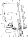
- a sewing machine 1 has a stand 2, an arm 3 and a head 4, so that together with a housing base plate 5, a total C-shaped structure of the sewing machine 1 results.
- a driven via a main drive not shown arm shaft drives a needle bar 6 with a sewing needle 7 fixed thereto up and down.
- the needle 7 passes through a stitch hole in a throat plate, which forms part of a support plate 8, which in turn represents the top of the housing base plate 5 of the sewing machine 1.
- the sewing machine 1 has a presser foot 9 for holding down sewing material during sewing, which is also referred to as a presser foot.
- the presser foot 9 is mounted on a presser foot rod 10.
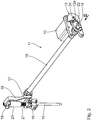
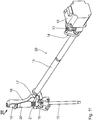
- a hold-down pressure exerted by the presser foot 9 while holding down on the sewing material and for releasing the presser foot is an assembly that in the Fig. 2 generally designated by the reference numeral 11.
- the assembly 11 comprises a pressure-adjusting device for setting the hold-down pressure, a fan device for releasing the presser foot and a common drive for these two devices.
- the pressure adjustment device and the fan device will be explained in detail below.
- the common drive is designed as a stepper motor 12.
- a drive shaft 12a (see e.g. Fig. 3 ) of the stepping motor 12 is oriented away from the presser foot rod 10, so that a free end of the drive shaft 12a, ie in the opposite direction to the viewing direction III of the view of Fig. 3 pointing to the viewer.
- the drive shaft of the stepping motor 12 is rotatably connected to a cam 13.
- the cam 13 cooperates with a cam lever 14 on the one hand for releasing the presser foot 9 and on the other hand for driving the pressure-adjusting device.
- the cam lever 14 cooperates with the cam 13 via a total Verschwenkweg the cam 13.
- the cam lever 14 is in turn rotatably connected to a fan shaft 15 which extends parallel to the arm shaft in the arm 3 of the sewing machine 1 and is rotatably mounted on a frame of the sewing machine 1.
- Rotatably connected to the fan shaft 15 is a fan lever 16 which cooperates with a presser foot driver 17 which is fixedly connected to the presser foot rod 10.
- the fan shaft 15 serves to transmit a shifting force from the cam lever 14 to the presser foot 9.
- the fan shaft 15 is eccentrically connected to a fan shaft longitudinal axis hinged to a pull rod 18 which is used for pressing in the Fig. 2 not shown presser foot 9 presses from above via a sleeve 19 against the compression spring 21.
- Compression spring 21 is arranged, which surrounds the presser foot 10 in sections helically.
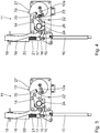
- Fig. 2 to 4 show the assembly 11 in the drive position "minimum hold-down pressure".
- Fig. 3 is in the Fig. 4 omitted a portion of a base plate of the cam lever 14 to further illustrate its interaction with the cam lever 14.
- the pull rod 18 exerts a minimum compressive force on the sleeve 19.
- the compression spring 21 is minimally biased.
- the force of the compression spring 21 is transmitted via the presser foot driver 17 to the presser foot rod 10, so that a corresponding, minimum hold-down pressure of the presser foot 9 during operation of the sewing machine 1 results.
- "minimum hold-down pressure" of the fan lever 16 is disengaged from the presser foot driver 17th
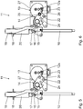
- FIGS. 5 and 6 show the drive position "Maximum foot lift". To reach this position, move from the position "Minimum Hold Down” to Fig. 2 to 4 the stepper motor 12 is operated so that its drive shaft by about 80 ° counterclockwise from the perspective of Fig. 3 to 6 is twisted.
- a second sensing pin 24 of the cam lever 14, which is a second scanning body of the cam lever 14, has thereby run clockwise on the cam 13 to a curve portion 25 in which the cam 13 in turn acts as a lever on the second sensing pin 24.
- the fan lever 16 presses the Presser-foot driver 17 against the pressure force of the compression spring 21 in the direction of the frame-fixed sleeve 20 upwards and takes the presser foot 10 for releasing the presser foot 9 with.
- the two sensing pins 22, 24 of the cam lever 14 are arranged separately from each other.
- the two sensing pins 22, 24 are fixedly connected to the cam lever 14.
- the two sensing pins 22, 24 are arranged so that they cooperate with the cam 13 in each case at least in a portion of the total Verschwenkweges the cam 13.
- the first sensing pin 22 cooperates with the cam 13 in the region of the cam recess 23.
- the second sensing pin 24 cooperates with the curve portion 25.
- the cam recess 23 on the one hand and the cam portion 25 on the other hand represent two concave cam portions of the cam disc 13. Between these two concave cam portions 23, 25, the cam disc 13 has a convex curve portion 26 which is formed in the shape of a nose of the curved line of the cam disc 13.
- FIGS. 7 and 8 show the drive position "average lift height” between the two drive positions described above “minimum hold pressure” and “maximum lift”.
- this drive position "average foot ventilation height”
- the convex curve section 26 engages between the two sensing pins 22, 24 and thus secures the engagement of the cam lever 14 on the cam disk via a positive engagement contribution 13.
- the presser foot 9 and the presser foot 10 its contact position on the cam 13 is secured.
- FIGS. 9 and 10 show the drive position "maximum hold-down pressure".
- the stepper motor 12 is switched so that its drive shaft, the cam 13 in comparison to the position after Fig. 3 has pivoted about 320 ° clockwise.
- the first sensing pin 22 of the cam lever 14 runs on the cam 13 up to a curve area 27 "maximum hold-down pressure”.
- the second sensing pin 24 is in this position "maximum hold-down pressure" out of engagement with the cam 13th
- the cam 13 and the cam lever 14 thus act together so that in a rotational direction of a rotation of the cam airing of the presser foot 9 takes place and in an opposite direction of rotation, a drive of the pressure-adjusting device.
- An adjustment range of the drive shaft of the stepping motor 12 between the cam lever position "minimum hold-down pressure" (see. Fig. 3 ) and the cam lever position “maximum hold-down pressure" (cf. Fig. 9 ) is more than 180 °.
- the stepper motor 12 can be actuated, for example, via a pedal of the sewing machine 1 by an operator for foot lifting.
- a default can be done via a control device 26, which in the Fig. 1 is shown schematically.
- the controller 26 is in signal communication with the stepper motor 12 in a manner not shown.
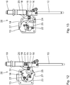
- FIG. 11 to 15 a further embodiment of an assembly 28 for specifying a hold-down pressure and for releasing a presser foot is explained below, which can be used instead of the above-described assembly 11 in the sewing machine 1.
- Assembly 28 for specifying a hold-down pressure and for releasing a presser foot is explained below, which can be used instead of the above-described assembly 11 in the sewing machine 1.
- Components and functions that correspond to those already discussed above with reference to the assembly 11 bear the same reference numerals and will not be discussed again in detail.
- the stepper motor 12 is arranged so that its drive shaft in the direction of the presser foot rod 10, so in turn in the opposite direction of the viewing direction XII to the viewer of Fig. 12 too, is oriented.
- the orientation of the drive shaft of the stepping motor 12 with respect to the pusher rod 10 is thus opposite to the assembly 11 in the assembly 28.
- Fig. 11 and 12 show the drive position "minimum hold-down pressure".
- the first sensing pin 22 of the cam lever 14 comes into contact with the cam 13 in the Kurvenaus Principleung 23rd
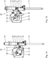
- the Fig. 13 shows the drive position "Maximum foot lift”.
- the stepper motor 12 of the assembly 28 is operated so that the fixedly connected to the drive shaft cam 13 by approximately 180 ° counterclockwise from the perspective of FIGS. 12 and 13 , starting from the drive position "minimum hold-down pressure" Fig. 12 , is twisted.
- the second sensing pin 24 dips into a further concave curve region 25 of the cam disc 13, which corresponds to the curve region 25 of the assembly 11.
- the cam lever 14 starting from the drive position "minimum foot pressure” is pivoted by approximately 45 ° counterclockwise.
- the fan lever 16 presses the presser foot driver 17 against the pressure force of the compression spring 21 in the direction of the frame-fixed sleeve 20 upwards, as above in connection with the FIGS. 5 and 6 already explained for the assembly 11.
- the Fig. 14 shows the drive position "middle foot lift", so an intermediate drive position between the positions “minimum foot pressure” after Fig. 12 and “Maximum Foot Ventilation” after Fig. 13 , In this drive position "average foot lifting height", the two drive pins 22, 24 simultaneously with the convex curve portion 26 of the cam 13 cooperate.
- Fig. 15 again shows the drive position "maximum hold-down pressure".
- the cam plate 13 of the assembly 28 is pivoted about 210 ° clockwise, which in turn takes place via the stepper motor 12.
- the first sensing pin 22 in this case runs on the cam 13 of the assembly 28 to the curve portion 27 "maximum hold-down pressure”.
- the cam lever 14 is in this drive position "maximum hold-down pressure” compared to the drive position "minimum foot pressure" in the view of the Fig. 12 and 15 pivoted about 90 ° clockwise.
- the curve region 27 also serves as a stop for referencing the stepping motor 12.
- the stepper motor 12 moves into the "maximum hold-down pressure" drive position until the first sensing pin 22 abuts the stop formed by the curve region 27.
- the curve region 27 designed as a stop does not require the use of further referencing sensors, which may otherwise be formed by a light barrier or an inductive switch.
- the two sensing pins 22 and 24 in the supervision of the 3 and 4 Seen between the fan shaft 15 and the drive shaft 12 a of the stepping motor 12 is arranged.
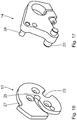
- FIGS. 16 and 17 show in perspective the cam 13 ( Fig. 16 ) and the cam lever ( Fig. 17 ) of the assembly 28.
- the cam 13 and the cam lever 14 of the assembly 28 can be used as a conversion assembly for retooling an existing drive assembly, the fan lever of this existing drive assembly originally has exactly one sensing pin.
Landscapes
- Engineering & Computer Science (AREA)
- Textile Engineering (AREA)
- Sewing Machines And Sewing (AREA)
Applications Claiming Priority (1)
| Application Number | Priority Date | Filing Date | Title |
|---|---|---|---|
| DE102018206088.6A DE102018206088A1 (de) | 2018-04-20 | 2018-04-20 | Nähmaschine |
Publications (2)
| Publication Number | Publication Date |
|---|---|
| EP3556923A1 true EP3556923A1 (fr) | 2019-10-23 |
| EP3556923B1 EP3556923B1 (fr) | 2020-08-05 |
Family
ID=65995639
Family Applications (1)
| Application Number | Title | Priority Date | Filing Date |
|---|---|---|---|
| EP19165705.5A Active EP3556923B1 (fr) | 2018-04-20 | 2019-03-28 | Machine à coudre |
Country Status (6)
| Country | Link |
|---|---|
| EP (1) | EP3556923B1 (fr) |
| JP (1) | JP6821738B2 (fr) |
| KR (1) | KR102632181B1 (fr) |
| CN (1) | CN110387643B (fr) |
| DE (1) | DE102018206088A1 (fr) |
| TW (1) | TWI828678B (fr) |
Cited By (6)
| Publication number | Priority date | Publication date | Assignee | Title |
|---|---|---|---|---|
| CN112267224A (zh) * | 2020-11-05 | 2021-01-26 | 琦星智能科技股份有限公司 | 一种剪线、抬压脚和针距调节的驱动装置 |
| CN112267223A (zh) * | 2020-11-03 | 2021-01-26 | 浙江沪龙科技股份有限公司 | 一种单电机驱动倒顺缝及抬压脚装置的机构及缝纫机 |
| CN112391746A (zh) * | 2020-10-30 | 2021-02-23 | 浙江广和缝纫机有限公司 | 包缝机抬压脚剪线装置 |
| CN114763636A (zh) * | 2021-01-13 | 2022-07-19 | 杰克科技股份有限公司 | 联调机构及缝纫机 |
| WO2022193743A1 (fr) * | 2021-03-16 | 2022-09-22 | 杰克科技股份有限公司 | Mécanisme de transmission pour machine à coudre |
| CN116695343A (zh) * | 2022-02-25 | 2023-09-05 | 高林股份有限公司 | 缝纫机的感测式压脚装置 |
Families Citing this family (4)
| Publication number | Priority date | Publication date | Assignee | Title |
|---|---|---|---|---|
| CN110878450B (zh) * | 2019-12-23 | 2021-11-02 | 杰克缝纫机股份有限公司 | 缝纫机剪线抬压脚和压脚压力调节装置及缝纫机 |
| CN112813590B (zh) * | 2021-01-29 | 2024-12-06 | 汇宝科技集团有限公司 | 一种缝纫机倒顺缝针距调节及抬压脚装置 |
| CN112726036A (zh) * | 2021-01-30 | 2021-04-30 | 浙江乐江机械有限公司 | 用于缝纫设备的传动件及缝纫机 |
| DE102024203789A1 (de) * | 2024-04-23 | 2025-10-23 | Dürkopp Adler GmbH | Nähmaschine, Nähanlage mit einer derartigen Nähmaschine sowie Verfahren zum Betrieb einer Nähmaschine |
Citations (3)
| Publication number | Priority date | Publication date | Assignee | Title |
|---|---|---|---|---|
| JPS5631787A (en) * | 1979-08-22 | 1981-03-31 | Riccar Sewing Machine Kk | Cloth pushing mechanism for sewing machine |
| EP2351881A1 (fr) * | 2009-12-18 | 2011-08-03 | Lässer AG | Machine à broder multitête |
| EP2975169A1 (fr) * | 2014-07-16 | 2016-01-20 | Dürkopp Adler AG | Machine à coudre |
Family Cites Families (11)
| Publication number | Priority date | Publication date | Assignee | Title |
|---|---|---|---|---|
| DE292059C (fr) * | ||||
| JP3079246B2 (ja) | 1995-07-13 | 2000-08-21 | 太平洋セメント株式会社 | 法面緑化擁壁 |
| JP2002159769A (ja) * | 2000-11-24 | 2002-06-04 | Janome Sewing Mach Co Ltd | 押え圧調整装置を備えたミシン及び押え上げ装置を備えたミシン |
| JP2006102400A (ja) * | 2004-10-08 | 2006-04-20 | Juki Corp | ミシン |
| DE102007052876A1 (de) * | 2007-11-07 | 2009-05-20 | Dürkopp Adler AG | Nähmaschine |
| DE102008016353A1 (de) * | 2008-03-29 | 2009-10-08 | Dürkopp Adler AG | Nähmaschine |
| CN202658372U (zh) | 2012-05-04 | 2013-01-09 | 东莞市顺机机械科技有限公司 | 一种缝纫机中压脚提升机构 |
| JP6606929B2 (ja) * | 2015-09-04 | 2019-11-20 | ブラザー工業株式会社 | ミシン |
| JP6603525B2 (ja) * | 2015-09-18 | 2019-11-06 | Juki株式会社 | ミシン |
| CN206127610U (zh) * | 2016-09-27 | 2017-04-26 | 台州市速普机电有限公司 | 一种缝纫机剪线抬压脚一体驱动结构 |
| CN208293220U (zh) * | 2018-02-08 | 2018-12-28 | 广州昊辰皮具有限公司 | 一种带压脚自动提升机构的电脑车 |
-
2018
- 2018-04-20 DE DE102018206088.6A patent/DE102018206088A1/de not_active Withdrawn
-
2019
- 2019-03-28 EP EP19165705.5A patent/EP3556923B1/fr active Active
- 2019-04-16 KR KR1020190044255A patent/KR102632181B1/ko active Active
- 2019-04-18 CN CN201910312803.3A patent/CN110387643B/zh active Active
- 2019-04-18 JP JP2019079189A patent/JP6821738B2/ja active Active
- 2019-04-19 TW TW108113749A patent/TWI828678B/zh active
Patent Citations (3)
| Publication number | Priority date | Publication date | Assignee | Title |
|---|---|---|---|---|
| JPS5631787A (en) * | 1979-08-22 | 1981-03-31 | Riccar Sewing Machine Kk | Cloth pushing mechanism for sewing machine |
| EP2351881A1 (fr) * | 2009-12-18 | 2011-08-03 | Lässer AG | Machine à broder multitête |
| EP2975169A1 (fr) * | 2014-07-16 | 2016-01-20 | Dürkopp Adler AG | Machine à coudre |
Cited By (7)
| Publication number | Priority date | Publication date | Assignee | Title |
|---|---|---|---|---|
| CN112391746A (zh) * | 2020-10-30 | 2021-02-23 | 浙江广和缝纫机有限公司 | 包缝机抬压脚剪线装置 |
| CN112267223A (zh) * | 2020-11-03 | 2021-01-26 | 浙江沪龙科技股份有限公司 | 一种单电机驱动倒顺缝及抬压脚装置的机构及缝纫机 |
| CN112267224A (zh) * | 2020-11-05 | 2021-01-26 | 琦星智能科技股份有限公司 | 一种剪线、抬压脚和针距调节的驱动装置 |
| CN114763636A (zh) * | 2021-01-13 | 2022-07-19 | 杰克科技股份有限公司 | 联调机构及缝纫机 |
| CN114763636B (zh) * | 2021-01-13 | 2023-06-20 | 杰克科技股份有限公司 | 联调机构及缝纫机 |
| WO2022193743A1 (fr) * | 2021-03-16 | 2022-09-22 | 杰克科技股份有限公司 | Mécanisme de transmission pour machine à coudre |
| CN116695343A (zh) * | 2022-02-25 | 2023-09-05 | 高林股份有限公司 | 缝纫机的感测式压脚装置 |
Also Published As
| Publication number | Publication date |
|---|---|
| EP3556923B1 (fr) | 2020-08-05 |
| KR102632181B1 (ko) | 2024-01-31 |
| TW201943909A (zh) | 2019-11-16 |
| CN110387643B (zh) | 2021-11-16 |
| CN110387643A (zh) | 2019-10-29 |
| JP6821738B2 (ja) | 2021-01-27 |
| KR20190122565A (ko) | 2019-10-30 |
| TWI828678B (zh) | 2024-01-11 |
| DE102018206088A1 (de) | 2019-10-24 |
| JP2019188142A (ja) | 2019-10-31 |
Similar Documents
| Publication | Publication Date | Title |
|---|---|---|
| EP3556923B1 (fr) | Machine à coudre | |
| EP2975169B1 (fr) | Machine à coudre | |
| DE3324518C1 (de) | Antriebsvorrichtung fuer mindestens eine hin- und hergehende Nadelstange einer Naeh-,Stick- oder Tuftingmaschine | |
| EP1372490A1 (fr) | Machine a suture chirurgicale | |
| EP2330241B1 (fr) | Machine à coudre | |
| EP1847641B1 (fr) | Couteau tireur de fil pour une machine à coudre | |
| EP2105526A1 (fr) | Machine à coudre | |
| DE102011102320A1 (de) | Nähmaschine mit Paillettenzuführvorrichtung | |
| EP2692925B1 (fr) | Couteau à tirer le fil pour une machine à coudre, module de coupe de fil et machine à coudre dotée d'un tel couteau à tirer le fil | |
| DE10136543C1 (de) | Nähmaschine, insbesondere Knopfloch-Nähmaschine, mit einer Nadelfaden-Klemm- und -Schneid-Einrichtung | |
| EP0348436B1 (fr) | Coupe-fil pour machines a coudre a point zig-zag | |
| DE4027060A1 (de) | Nadelfaden-halteeinrichtung fuer eine naehmaschine | |
| EP0891513A1 (fr) | Dispositif pour appliquer des rivets, boutons ou similaires sur des matieres textiles | |
| EP0420856B1 (fr) | Coupe-fil pour machines a coudre | |
| EP4640936A1 (fr) | Machine à coudre, installation de couture dotée d'une telle machine à coudre et procédé de fonctionnement d'une machine à coudre | |
| DE4324741C2 (de) | Stick- oder Nähmaschine mit einer Einrichtung zum Fadenwischen | |
| EP3399088B1 (fr) | Module de production et machine à coudre pour produire un début de fil supérieur de couture dépassant d'une valeur de consigne | |
| DE19851021A1 (de) | Einrichtung zum Betätigen einer Kupplung für die Bindeeinrichtung einer Großballenpresse | |
| EP3133198B1 (fr) | Machine a coudre et composant de machine a coudre | |
| EP3023527B1 (fr) | Module d'entrainement de machine a coudre et machine a coudre dotee d'un tel module d'entrainement | |
| DE102006039155A1 (de) | Nähmaschine mit automatischer Fadenschneidvorrichtung | |
| DE3348054C2 (fr) | ||
| EP3088590A1 (fr) | Machine à coudre | |
| DE102005059553B4 (de) | Greiferschaltvorrichtung einer Nähmaschine | |
| DE102015207996B3 (de) | Nähmaschine |
Legal Events
| Date | Code | Title | Description |
|---|---|---|---|
| PUAI | Public reference made under article 153(3) epc to a published international application that has entered the european phase |
Free format text: ORIGINAL CODE: 0009012 |
|
| STAA | Information on the status of an ep patent application or granted ep patent |
Free format text: STATUS: THE APPLICATION HAS BEEN PUBLISHED |
|
| AK | Designated contracting states |
Kind code of ref document: A1 Designated state(s): AL AT BE BG CH CY CZ DE DK EE ES FI FR GB GR HR HU IE IS IT LI LT LU LV MC MK MT NL NO PL PT RO RS SE SI SK SM TR |
|
| AX | Request for extension of the european patent |
Extension state: BA ME |
|
| STAA | Information on the status of an ep patent application or granted ep patent |
Free format text: STATUS: REQUEST FOR EXAMINATION WAS MADE |
|
| STAA | Information on the status of an ep patent application or granted ep patent |
Free format text: STATUS: EXAMINATION IS IN PROGRESS |
|
| 17P | Request for examination filed |
Effective date: 20200206 |
|
| RBV | Designated contracting states (corrected) |
Designated state(s): AL AT BE BG CH CY CZ DE DK EE ES FI FR GB GR HR HU IE IS IT LI LT LU LV MC MK MT NL NO PL PT RO RS SE SI SK SM TR |
|
| 17Q | First examination report despatched |
Effective date: 20200306 |
|
| GRAP | Despatch of communication of intention to grant a patent |
Free format text: ORIGINAL CODE: EPIDOSNIGR1 |
|
| STAA | Information on the status of an ep patent application or granted ep patent |
Free format text: STATUS: GRANT OF PATENT IS INTENDED |
|
| INTG | Intention to grant announced |
Effective date: 20200415 |
|
| GRAS | Grant fee paid |
Free format text: ORIGINAL CODE: EPIDOSNIGR3 |
|
| GRAA | (expected) grant |
Free format text: ORIGINAL CODE: 0009210 |
|
| STAA | Information on the status of an ep patent application or granted ep patent |
Free format text: STATUS: THE PATENT HAS BEEN GRANTED |
|
| AK | Designated contracting states |
Kind code of ref document: B1 Designated state(s): AL AT BE BG CH CY CZ DE DK EE ES FI FR GB GR HR HU IE IS IT LI LT LU LV MC MK MT NL NO PL PT RO RS SE SI SK SM TR |
|
| REG | Reference to a national code |
Ref country code: GB Ref legal event code: FG4D Free format text: NOT ENGLISH |
|
| REG | Reference to a national code |
Ref country code: CH Ref legal event code: EP |
|
| REG | Reference to a national code |
Ref country code: AT Ref legal event code: REF Ref document number: 1298837 Country of ref document: AT Kind code of ref document: T Effective date: 20200815 |
|
| REG | Reference to a national code |
Ref country code: DE Ref legal event code: R096 Ref document number: 502019000116 Country of ref document: DE |
|
| REG | Reference to a national code |
Ref country code: IE Ref legal event code: FG4D Free format text: LANGUAGE OF EP DOCUMENT: GERMAN |
|
| REG | Reference to a national code |
Ref country code: LT Ref legal event code: MG4D |
|
| REG | Reference to a national code |
Ref country code: NL Ref legal event code: MP Effective date: 20200805 |
|
| PG25 | Lapsed in a contracting state [announced via postgrant information from national office to epo] |
Ref country code: LT Free format text: LAPSE BECAUSE OF FAILURE TO SUBMIT A TRANSLATION OF THE DESCRIPTION OR TO PAY THE FEE WITHIN THE PRESCRIBED TIME-LIMIT Effective date: 20200805 Ref country code: HR Free format text: LAPSE BECAUSE OF FAILURE TO SUBMIT A TRANSLATION OF THE DESCRIPTION OR TO PAY THE FEE WITHIN THE PRESCRIBED TIME-LIMIT Effective date: 20200805 Ref country code: BG Free format text: LAPSE BECAUSE OF FAILURE TO SUBMIT A TRANSLATION OF THE DESCRIPTION OR TO PAY THE FEE WITHIN THE PRESCRIBED TIME-LIMIT Effective date: 20201105 Ref country code: ES Free format text: LAPSE BECAUSE OF FAILURE TO SUBMIT A TRANSLATION OF THE DESCRIPTION OR TO PAY THE FEE WITHIN THE PRESCRIBED TIME-LIMIT Effective date: 20200805 Ref country code: PT Free format text: LAPSE BECAUSE OF FAILURE TO SUBMIT A TRANSLATION OF THE DESCRIPTION OR TO PAY THE FEE WITHIN THE PRESCRIBED TIME-LIMIT Effective date: 20201207 Ref country code: GR Free format text: LAPSE BECAUSE OF FAILURE TO SUBMIT A TRANSLATION OF THE DESCRIPTION OR TO PAY THE FEE WITHIN THE PRESCRIBED TIME-LIMIT Effective date: 20201106 Ref country code: NO Free format text: LAPSE BECAUSE OF FAILURE TO SUBMIT A TRANSLATION OF THE DESCRIPTION OR TO PAY THE FEE WITHIN THE PRESCRIBED TIME-LIMIT Effective date: 20201105 Ref country code: SE Free format text: LAPSE BECAUSE OF FAILURE TO SUBMIT A TRANSLATION OF THE DESCRIPTION OR TO PAY THE FEE WITHIN THE PRESCRIBED TIME-LIMIT Effective date: 20200805 Ref country code: FI Free format text: LAPSE BECAUSE OF FAILURE TO SUBMIT A TRANSLATION OF THE DESCRIPTION OR TO PAY THE FEE WITHIN THE PRESCRIBED TIME-LIMIT Effective date: 20200805 |
|
| PG25 | Lapsed in a contracting state [announced via postgrant information from national office to epo] |
Ref country code: RS Free format text: LAPSE BECAUSE OF FAILURE TO SUBMIT A TRANSLATION OF THE DESCRIPTION OR TO PAY THE FEE WITHIN THE PRESCRIBED TIME-LIMIT Effective date: 20200805 Ref country code: NL Free format text: LAPSE BECAUSE OF FAILURE TO SUBMIT A TRANSLATION OF THE DESCRIPTION OR TO PAY THE FEE WITHIN THE PRESCRIBED TIME-LIMIT Effective date: 20200805 Ref country code: LV Free format text: LAPSE BECAUSE OF FAILURE TO SUBMIT A TRANSLATION OF THE DESCRIPTION OR TO PAY THE FEE WITHIN THE PRESCRIBED TIME-LIMIT Effective date: 20200805 Ref country code: PL Free format text: LAPSE BECAUSE OF FAILURE TO SUBMIT A TRANSLATION OF THE DESCRIPTION OR TO PAY THE FEE WITHIN THE PRESCRIBED TIME-LIMIT Effective date: 20200805 Ref country code: IS Free format text: LAPSE BECAUSE OF FAILURE TO SUBMIT A TRANSLATION OF THE DESCRIPTION OR TO PAY THE FEE WITHIN THE PRESCRIBED TIME-LIMIT Effective date: 20201205 |
|
| PG25 | Lapsed in a contracting state [announced via postgrant information from national office to epo] |
Ref country code: SM Free format text: LAPSE BECAUSE OF FAILURE TO SUBMIT A TRANSLATION OF THE DESCRIPTION OR TO PAY THE FEE WITHIN THE PRESCRIBED TIME-LIMIT Effective date: 20200805 Ref country code: DK Free format text: LAPSE BECAUSE OF FAILURE TO SUBMIT A TRANSLATION OF THE DESCRIPTION OR TO PAY THE FEE WITHIN THE PRESCRIBED TIME-LIMIT Effective date: 20200805 Ref country code: EE Free format text: LAPSE BECAUSE OF FAILURE TO SUBMIT A TRANSLATION OF THE DESCRIPTION OR TO PAY THE FEE WITHIN THE PRESCRIBED TIME-LIMIT Effective date: 20200805 |
|
| REG | Reference to a national code |
Ref country code: DE Ref legal event code: R097 Ref document number: 502019000116 Country of ref document: DE |
|
| PG25 | Lapsed in a contracting state [announced via postgrant information from national office to epo] |
Ref country code: AL Free format text: LAPSE BECAUSE OF FAILURE TO SUBMIT A TRANSLATION OF THE DESCRIPTION OR TO PAY THE FEE WITHIN THE PRESCRIBED TIME-LIMIT Effective date: 20200805 |
|
| PLBE | No opposition filed within time limit |
Free format text: ORIGINAL CODE: 0009261 |
|
| STAA | Information on the status of an ep patent application or granted ep patent |
Free format text: STATUS: NO OPPOSITION FILED WITHIN TIME LIMIT |
|
| PG25 | Lapsed in a contracting state [announced via postgrant information from national office to epo] |
Ref country code: SK Free format text: LAPSE BECAUSE OF FAILURE TO SUBMIT A TRANSLATION OF THE DESCRIPTION OR TO PAY THE FEE WITHIN THE PRESCRIBED TIME-LIMIT Effective date: 20200805 |
|
| 26N | No opposition filed |
Effective date: 20210507 |
|
| PG25 | Lapsed in a contracting state [announced via postgrant information from national office to epo] |
Ref country code: IT Free format text: LAPSE BECAUSE OF FAILURE TO SUBMIT A TRANSLATION OF THE DESCRIPTION OR TO PAY THE FEE WITHIN THE PRESCRIBED TIME-LIMIT Effective date: 20200805 |
|
| PG25 | Lapsed in a contracting state [announced via postgrant information from national office to epo] |
Ref country code: SI Free format text: LAPSE BECAUSE OF FAILURE TO SUBMIT A TRANSLATION OF THE DESCRIPTION OR TO PAY THE FEE WITHIN THE PRESCRIBED TIME-LIMIT Effective date: 20200805 |
|
| PG25 | Lapsed in a contracting state [announced via postgrant information from national office to epo] |
Ref country code: MC Free format text: LAPSE BECAUSE OF FAILURE TO SUBMIT A TRANSLATION OF THE DESCRIPTION OR TO PAY THE FEE WITHIN THE PRESCRIBED TIME-LIMIT Effective date: 20200805 |
|
| REG | Reference to a national code |
Ref country code: BE Ref legal event code: MM Effective date: 20210331 |
|
| PG25 | Lapsed in a contracting state [announced via postgrant information from national office to epo] |
Ref country code: FR Free format text: LAPSE BECAUSE OF NON-PAYMENT OF DUE FEES Effective date: 20210331 Ref country code: LU Free format text: LAPSE BECAUSE OF NON-PAYMENT OF DUE FEES Effective date: 20210328 Ref country code: IE Free format text: LAPSE BECAUSE OF NON-PAYMENT OF DUE FEES Effective date: 20210328 |
|
| PG25 | Lapsed in a contracting state [announced via postgrant information from national office to epo] |
Ref country code: BE Free format text: LAPSE BECAUSE OF NON-PAYMENT OF DUE FEES Effective date: 20210331 |
|
| REG | Reference to a national code |
Ref country code: CH Ref legal event code: PL |
|
| PG25 | Lapsed in a contracting state [announced via postgrant information from national office to epo] |
Ref country code: LI Free format text: LAPSE BECAUSE OF NON-PAYMENT OF DUE FEES Effective date: 20220331 Ref country code: CH Free format text: LAPSE BECAUSE OF NON-PAYMENT OF DUE FEES Effective date: 20220331 |
|
| P01 | Opt-out of the competence of the unified patent court (upc) registered |
Effective date: 20230512 |
|
| PG25 | Lapsed in a contracting state [announced via postgrant information from national office to epo] |
Ref country code: CY Free format text: LAPSE BECAUSE OF FAILURE TO SUBMIT A TRANSLATION OF THE DESCRIPTION OR TO PAY THE FEE WITHIN THE PRESCRIBED TIME-LIMIT Effective date: 20200805 |
|
| PG25 | Lapsed in a contracting state [announced via postgrant information from national office to epo] |
Ref country code: HU Free format text: LAPSE BECAUSE OF FAILURE TO SUBMIT A TRANSLATION OF THE DESCRIPTION OR TO PAY THE FEE WITHIN THE PRESCRIBED TIME-LIMIT; INVALID AB INITIO Effective date: 20190328 |
|
| GBPC | Gb: european patent ceased through non-payment of renewal fee |
Effective date: 20230328 |
|
| PG25 | Lapsed in a contracting state [announced via postgrant information from national office to epo] |
Ref country code: GB Free format text: LAPSE BECAUSE OF NON-PAYMENT OF DUE FEES Effective date: 20230328 |
|
| PG25 | Lapsed in a contracting state [announced via postgrant information from national office to epo] |
Ref country code: GB Free format text: LAPSE BECAUSE OF NON-PAYMENT OF DUE FEES Effective date: 20230328 |
|
| PG25 | Lapsed in a contracting state [announced via postgrant information from national office to epo] |
Ref country code: MK Free format text: LAPSE BECAUSE OF FAILURE TO SUBMIT A TRANSLATION OF THE DESCRIPTION OR TO PAY THE FEE WITHIN THE PRESCRIBED TIME-LIMIT Effective date: 20200805 |
|
| PG25 | Lapsed in a contracting state [announced via postgrant information from national office to epo] |
Ref country code: MT Free format text: LAPSE BECAUSE OF FAILURE TO SUBMIT A TRANSLATION OF THE DESCRIPTION OR TO PAY THE FEE WITHIN THE PRESCRIBED TIME-LIMIT Effective date: 20200805 |
|
| REG | Reference to a national code |
Ref country code: AT Ref legal event code: MM01 Ref document number: 1298837 Country of ref document: AT Kind code of ref document: T Effective date: 20240328 |
|
| PG25 | Lapsed in a contracting state [announced via postgrant information from national office to epo] |
Ref country code: AT Free format text: LAPSE BECAUSE OF NON-PAYMENT OF DUE FEES Effective date: 20240328 |
|
| PG25 | Lapsed in a contracting state [announced via postgrant information from national office to epo] |
Ref country code: TR Free format text: LAPSE BECAUSE OF FAILURE TO SUBMIT A TRANSLATION OF THE DESCRIPTION OR TO PAY THE FEE WITHIN THE PRESCRIBED TIME-LIMIT Effective date: 20200805 |
|
| PGFP | Annual fee paid to national office [announced via postgrant information from national office to epo] |
Ref country code: AT Payment date: 20260410 Year of fee payment: 5 |
|
| PGFP | Annual fee paid to national office [announced via postgrant information from national office to epo] |
Ref country code: RO Payment date: 20260320 Year of fee payment: 8 |
|
| PGFP | Annual fee paid to national office [announced via postgrant information from national office to epo] |
Ref country code: CZ Payment date: 20260316 Year of fee payment: 8 |
|
| PGFP | Annual fee paid to national office [announced via postgrant information from national office to epo] |
Ref country code: DE Payment date: 20260522 Year of fee payment: 8 |