EP3556485A1 - Verfahren zur bearbeitung des gewindes eines gewalzten rohrs, walzkopf, vorrichtung, modul, fertigungslinie und produkt daraus - Google Patents
Verfahren zur bearbeitung des gewindes eines gewalzten rohrs, walzkopf, vorrichtung, modul, fertigungslinie und produkt daraus Download PDFInfo
- Publication number
- EP3556485A1 EP3556485A1 EP17882130.2A EP17882130A EP3556485A1 EP 3556485 A1 EP3556485 A1 EP 3556485A1 EP 17882130 A EP17882130 A EP 17882130A EP 3556485 A1 EP3556485 A1 EP 3556485A1
- Authority
- EP
- European Patent Office
- Prior art keywords
- rolling
- thread
- rolling wheel
- head
- pipe thread
- Prior art date
- Legal status (The legal status is an assumption and is not a legal conclusion. Google has not performed a legal analysis and makes no representation as to the accuracy of the status listed.)
- Granted
Links
Images


Classifications
-
- B—PERFORMING OPERATIONS; TRANSPORTING
- B21—MECHANICAL METAL-WORKING WITHOUT ESSENTIALLY REMOVING MATERIAL; PUNCHING METAL
- B21H—MAKING PARTICULAR METAL OBJECTS BY ROLLING, e.g. SCREWS, WHEELS, RINGS, BARRELS, BALLS
- B21H3/00—Making helical bodies or bodies having parts of helical shape
- B21H3/02—Making helical bodies or bodies having parts of helical shape external screw-threads ; Making dies for thread rolling
- B21H3/04—Making by means of profiled-rolls or die rolls
- B21H3/042—Thread-rolling heads
-
- B—PERFORMING OPERATIONS; TRANSPORTING
- B21—MECHANICAL METAL-WORKING WITHOUT ESSENTIALLY REMOVING MATERIAL; PUNCHING METAL
- B21B—ROLLING OF METAL
- B21B27/00—Rolls, roll alloys or roll fabrication; Lubricating, cooling or heating rolls while in use
- B21B27/02—Shape or construction of rolls
- B21B27/024—Rolls for bars, rods, rounds, tubes, wire or the like
-
- B—PERFORMING OPERATIONS; TRANSPORTING
- B21—MECHANICAL METAL-WORKING WITHOUT ESSENTIALLY REMOVING MATERIAL; PUNCHING METAL
- B21H—MAKING PARTICULAR METAL OBJECTS BY ROLLING, e.g. SCREWS, WHEELS, RINGS, BARRELS, BALLS
- B21H3/00—Making helical bodies or bodies having parts of helical shape
- B21H3/02—Making helical bodies or bodies having parts of helical shape external screw-threads ; Making dies for thread rolling
- B21H3/04—Making by means of profiled-rolls or die rolls
Definitions
- the present invention relates to a method, a rolling head, an apparatus, a module and a production line for rolling external pipe thread on a steel pipe or a hollow blank, especially a common steel pipe, and pre-formed thread products made from said method, rolling head, apparatus, module and production line belonging to the threading, especially the external pipe threading, mechanical field.
- the external pipe thread by rolling has significant advantages of good quality, good sealing performance and high mechanical connection strength, and is valued by more and more people.
- outer diameter, wall thickness and other parameters of existing general steel pipe are formulated based on the cutting process requirements.
- the outer diameter is too large and the steep pipe has a certain degree of non-roundness.
- the both constitute two biggest problems for rolling an external pipe thread.
- the problem of the large outer diameter can be solved by methods such as axial punching of a conical surface or a cylindrical surface or a radial rolling to reducing diameter, or using a medium-diameter pipe conforming to the rolling requirement.
- the method adopted at present for solving the irregularity of non-roundness problem is a kind of axially punched perfect conical surface disclosed in patent CN1251820C or a method of firstly cutting the perfect conical surface with the tool in the external pipe thread section of the steel pipe for processing pipe and then performing the conical external pipe thread rolling processing disclosed by the patent CN2582780Y .
- Axially punching has the problems of complex apparatus and damage to the steel pipe, and firstly cutting the perfect conical surface with the tool in the external pipe thread section needs high processing precision, such as high concentricity of the workpiece and the tool, which can not be easily achieved in construction site for installing the pipe network, at the same time, the zinc layer on the surface of galvanized steel pipe was destroyed.
- the market needs new external pipe thread processing technology and pipe external pipe thread processing apparatus which has reasonable structural design and high applicability.
- the purpose of the present invention is to provide a method, a module and an apparatus for rolling external pipe thread and a production line thereof with high applicability. More specifically, the present invention provides a method, module, apparatus and rolling production line that can use conventional steel pipe having a standard outer diameter and non-roundness as a blank, without applying a preparatory process that need a die stamping or cutting a conical surface with a tool, and complete the preparation process by the pre-rolling of the present invention, and then form external pipe thread by rolling. In addition, the present invention also provides a product with pre-formed thread products made from said method, rolling head, apparatus, module and production line
- the present invention provides a method for rolling an external pipe thread, characterized in that it comprises a hollow blank rolled by a first rolling wheel group and a second rolling wheel group, wherein the first rolling wheel group comprises at least three circumferentially arranged the first rolling wheels, preferably comprising at least four circumferentially arranged the first rolling wheels, the second rolling wheel group comprises at least two circumferentially arranged the second rolling wheels, preferably comprising at least three circumferentially arranged the second rolling wheels, wherein the first rolling wheels are pre-formed rolling wheels with outer surface, and outer surface of the second rolling wheels have external pipe thread forming portion, and the method includes the following steps:
- the surface roughness Ra of the thread on the outer surface of the hollow blank is less than 0.125, the surface hardness is increased by 20% to 100%, and the non-roundness is reduced by 10% to 50%; particularly preferably, the protective coating is intact.
- the method of the present invention is used for rolling external pipe thread, there is no need to perform any processing step (including not requiring external chamfering) prior to performing the rolling process of step 1, as that thread are formed entirely by rolling, the surface of the hollow blank, especially the surface zinc layer of the galvanized pipe, is protected and strengthen, thus the material is saved, the environment is protected. And the real non-cutting processing has been realized, and the operation method is the same as that of the current process of cutting the external pipe threads.
- the rolling process of the first rolling wheel group is an annular rolling
- the rolling process of the second rolling wheel group is a thread rolling
- the hollow blank has non-roundness greater than 100 um.
- the rolling process of the first rolling wheel group and the second rolling wheel group is selected from one of the following combinations:
- both the number of the first rolling wheels in the first rolling wheel group and the number of the second rolling wheels in the second rolling wheel group is no more than 15, preferably 3,4, 5, 6, 7, 8, or 9; or when used to process an external pipe thread on a hollow blank having a size between 2 and 4 inches, both the number of the first rolling wheels in the first rolling wheel group and the second rolling wheels in the second rolling wheel group does not exceed 19, preferably 4, 5, 6, 7, 8, 9, 10, or 11; or when used to process an external pipe thread on a hollow blank having a size of 4 inches or more, both the number of the first rolling wheels in the first rolling wheel group and the number of the second rolling wheels in the second rolling wheel group is no more than 35, preferably 4, 5, 6, 7, 8, 9, 10, 11, 12, 13, 14, 15, 16, 17, 18, 19 or 20.
- the number of the first rolling wheels in the first rolling wheel group is different from the number of the second rolling wheels in the second rolling wheel group by 1 to 11, more preferably 1, 3, 5 or 7.
- the number of the first rolling wheels in the first rolling wheel group is 4, and the number of the second rolling wheels in the second rolling wheel group is 5 or 7 or 9 or 11; or the number of the first rolling wheels in the first rolling wheel group is 5 and the number of the second rolling wheels in the second rolling wheel group is 6 or 8 or 10 or 12.
- the number of the first rolling wheels in the first rolling wheel group is 4 and the number of the second rolling wheels in the second rolling wheel group is 3 ; or the number of the first rolling wheels in the first rolling wheel group is 5 and the number of the second rolling wheels in the second rolling wheel group is 4; or the number of the first rolling wheels in the first rolling wheel group is 6and the number of the second rolling wheels in the second rolling wheel group is5or 3; or the number of the first rolling wheels in the first rolling wheel group is 7, and the number of the second rolling wheels in the second rolling wheel group is 6 or 4; or the number of the first rolling wheels in the first rolling wheel group is 8, and the number of the second
- the first rolling wheel group rolls the outer surface of the portion of the hollow blank to be provided with thread into a conical surface, and the taper of the conical surface is 2°-12°, preferably 3°30 "-8°30".
- the first rolling wheels has one or more of the following features:
- the first rolling wheels is a conical rolling wheel with a per-formed thread, and the axis thereof has a deflection angle of not more than 9 degrees in the vertical direction with respect to the axis of the hollow blank to be processed, preferably, the deflection angle is less than 3 degrees.
- the rolling wheels in the rolling wheel group is an annular rolling wheel or a thread rolling wheel, preferably, the rolling process of the first rolling wheel group is the annular rolling wheel, and the rolling process of the second rolling wheel group is the thread rolling wheel. In this way, it can make full use of the convenience of the annular rolling wheel pair teeth and the two functions of a thread rolling wheel: straightening and external pipe thread forming.
- Another aspect of the present invention provides a method for rolling an external pipe thread, characterized in which is to perform external pipe thread forming rolling on the outer surface of the pre-forming rolled hollow blank, wherein the pre-formed rolling refers to the process of rolling the outer surface of the hollow blank into a threaded cylindrical or threaded conical surface or a threaded cylindrical conical mixing surface by the first rolling wheel group, and the first rolling wheel group comprises at least 3 circumferentially arranged first rolling wheels with pre-formed thread, preferably, at least 4 circumferentially arranged first rolling wheels with pre-formed thread, and the external pipe thread forming rolling is performed by the second rolling wheel group including at least 2 circumferentially arranged second rolling wheels, preferably, comprises at least 3 circumferentially arranged second rolling wheels, which having an external pipe thread forming portion, and wherein number of the first rolling wheels in the first rolling wheel group and the number of the second rolling wheels in the second rolling wheel group is odd-even different, preferably , the number of the first rolling wheels in the first rolling wheel group is greater
- the first rolling wheels is a conical rolling wheel with a per-formed thread, and the axis thereof has a deflection angle of not more than 9 degrees in the vertical direction with respect to the axis of the hollow blank to be processed, preferably, the deflection angle is less than 3 degrees; preferably the first rolling wheel group rolls the outer surface of the portion of the hollow blank to be provided with external pipe thread into a conical surface, and the taper of the conical surface is 2°-12°, preferably 3°30 "-8°30".
- a rolling head comprising at least 2 circumferentially arranged rolling wheels (81 or 82), a first rolling wheel disk (60A or 70A), a second rolling wheel disc (60B or 70B) and a connecting pin (602 or 702), wherein the number of rolling wheels , preferably ,at least 3, and the further character is that the first rolling wheel disc and the second rolling wheel disc are provided with radial grooves (71) corresponding to each other, workpiece working holes (704) and pin holes (701), and the rolling wheel (81 or 82) cooperates with the radial grooves (71) on the first and second rolling wheel discs via its rolling wheel axle, and mounting surfaces of the radial grooves (71) for the rolling wheel (81 or 82) is an inclined plane or a plane (703); the first rolling wheel disc and the second rolling wheel disc are connected and fixed with each other through the connecting pin shafts (601 or 701) cooperating with the pin holes (602 or 702) to form a rolling head coaxially, and the rolling wheel shafts (8
- the rolling wheel shafts (83) are mounted on the radial groove (71) of the rolling wheel disc through the inclined planes (832a, 832b), wherein the axis of the rolling wheel forms an included angle with the inclined plane or the plane (832a, 832b).
- the included angle is less than 9 degrees, more preferably less than 3 degrees.
- the inclined plane is a plane, the angle is 0.
- the first rolling wheel group is a rolling wheel with a pre-formed thread
- the rolling wheel has a cutting blade integrally formed with the rolling wheel.
- the first rolling wheel group is a conical rolling wheel with a pre-formed thread
- the taper of the conical rolling wheel is 2°-12°, preferably 3°30 "-8°30".
- the rolling wheel is an annular rolling wheel and has an external pipe thread forming portion, or the rolling head of the present invention is used as the external pipe thread rolling wheel , the rolling wheel is a thread rolling wheel.
- the annular rolling wheel meets the following conditions: there is a deflection angle of not more than 9 degrees for the axis of the annular rolling wheel and the axis of the workpiece working hole in the vertical direction, and there is also an initial part of the thread on the surface of the rolling wheel, and the initial part of the thread refers to the thread that in the thread rolling process firstly contacts with the hollow blank and meets the following conditions: A total of N annular rolling wheels are arranged in the second rolling head.
- the initial part of the next rolling wheel Ri + 1 along the same clockwise direction is the thread obtained based on the initial partial thread of the rolling wheel Ri and extending a distance of 1/N pitch according to the original thread form and pitch in the direction of the rolling wheel Ri axis.
- the rolling wheel is a thread rolling wheel, which has an external pipe thread forming portion.
- the axis line of the rolling wheel forms an included angle of 0 degrees with the planes (832a, 832b).
- the rolling head further comprises a first adjusting disc (76A), a second adjusting disc (76B) and an adjusting disc pin shaft (763), and the first adjusting disc and the second adjusting disc are provided with positioning and installing blind holes (766), arc-shaped grooves (762), workpiece working holes (764) and pin holes (761) corresponding to each other; the first adjusting disc and the second adjusting discs are respectively and coaxially mounted on the outer sides of the first rolling wheel disc and the second rolling wheel disc through the positioning and installing blind holes (766), and are mutually connected by the adjusting disc pin shaft (763); both ends of the rolling wheel axle (83) also has an extension (833) on the outside of the inclined plane or the plane, the extension of the rolling wheel axle (833) being mounted in the arc-shaped grooves (762) in the adjusting disc, turning the adjusting disc can drive the rolling wheel shaft (83) to slide in the arc-shaped grooves (762) so as to drive the rolling wheel shaft (83) to move radially in the
- the rolling head further comprises a sliding piece, and the extension of the rolling wheel shaft cooperates with a shaft hole of the sliding piece and is installed in the arc-shaped slot (762) of the adjusting disk through the sliding piece 836; rotating the adjusting disc (76) can drive the sliding piece to slide in the arc-shaped groove (762) to drive the rolling wheel shaft (83) to move radially in the radial groove (71) of the rolling wheel disc (70); or equivalently more preferably, the rolling head further comprises a control adjusting rod (122) installed at the end of the rolling head on the side where rolling is completed; during the rolling process, when the hollow blank contacts the control adjusting rod (122), the control adjusting rod (122) can drive the photoelectric sensing device to work and control the rotation of the first adjusting disc and the second adjusting disc to control start and stop of the rolling process.
- a control adjusting rod (122) installed at the end of the rolling head on the side where rolling is completed; during the rolling process, when the hollow blank contacts the control adjusting rod (122), the control adjusting rod
- the rolling head further comprises a control adjusting lever (121) mounted on the top or the bottom of the rolling head on the side where rolling is completed.
- the control adjusting lever (121) can drive the photoelectric sensing device to work and control the rotation of the first adjusting disc and the second adjusting disc to control the start and stop of the rolling process.
- relative rotational position angle detecting means (123) is provided between the first rolling wheel disc and the first adjusting disc or between the second rolling wheel disc and the second adjusting disc.
- the present invention also provides an external pipe thread rolling apparatus, which comprises at least one of the above-mentioned rolling heads, show as Figs.21,22 , 24 , 26 and Fig.32 .
- the present invention further provides a module for rolling an external pipe thread, characterized in that it comprises a first rolling head and a second rolling head, wherein the first rolling head comprises at least three circumferentially arranged first rolling wheels, preferably, comprises at least four circumferentially arranged first rolling wheels, the first rolling wheel is a rolling wheel with a pre-formed thread; and the second rolling head comprises at least two circumferentially arranged second rolling wheels, preferably, comprises at least three circumferentially arranged second rolling wheels having an external pipe thread forming portion; and number of the first rolling wheels in the first rolling wheel group and the number of the second rolling wheels in the second rolling wheel group is odd-even different, preferably, the number of the first rolling wheels in the first rolling wheel group is greater than the number of the second rolling wheels in the second rolling wheel group; and the pitch of the pre-formed thread is equal to the pitch of thread on external pipe thread forming portion, the depth of pre-formed thread is smaller than the depth of thread on external thread forming portion.
- the tooth profile of the pre-formed thread does not exceed the tooth profile of the external pipe thread forming portion, and further, the pre-formed thread is a sinusoidal thread, and more preferably, the pre-formed thread is a sinusoidal thread.
- the first rolling wheels in the first rolling wheel group is an annular rolling
- the second rolling wheels in the second rolling wheel group is a thread rolling
- the first rolling wheel is a conical rolling wheel with a pre-formed thread,
- the taper of the conical rolling wheel is 2°-12°, preferably 3°30 "-8°30"
- the present invention also provides a module for rolling an external pipe thread, comprising a first rolling head and a second rolling head which are combined into one body and the first rolling head and the second rolling head are arranged coaxially with the hollow blank to be processed, wherein the first rolling head is arranged on the side close to the start of the external pipe thread processed; more preferably, the first rolling head comprises a corresponding first rolling wheel disc (70A), a second rolling wheel disc (70B) and a connecting pin (763).
- the first rolling wheel disc (70A) and the second rolling wheel disc (70B) are provided with radial grooves (71), workpiece processing holes (704) and pin holes (701) corresponding to each other.
- the rolling wheel (81 or 82) cooperates with the radial grooves (71) on the first rolling wheel disc (70A) and the second rolling wheel disc (70B) via the rolling wheel shaft (83), and mounting surface of the radial groove (71) and the rolling wheel (81 or 82) is an inclined plane or a plane (703).
- the first rolling wheel disc (70A) and the second rolling wheel disc (70B) are fixedly connected to each other by a connecting pin shaft (763) matched with the pin hole (701), coaxially formed as the rolling head, and two ends of the rolling wheel shaft (83) is provided with inclined planes or planes (832a, 832b) parallel to each other and the rolling wheel axle (83) is mounted on a radial groove (71) of the rolling wheel disc through the inclined planes or planes (832a, 832b).
- the axis X of the rolling wheel forms an included angle with the inclined planes (832a, 832b), and the included angle is less than 9 degrees, preferably less than 3 degrees, when the rolling wheel is a thread rolling, the inclined plane is a plane, the angle is 0.
- the first rolling head further comprises a control adjusting rod.
- the control adjusting rod is installed on the top or the tail of the rolling head on the side where the rolling is finished.
- the second rolling head also comprises a corresponding first rolling wheel disk, a second rolling wheel disk and a connecting pin.
- the first rolling wheel disk and the second rolling wheel disk are provided with radial grooves, workpiece processing holes, and pin holes corresponding to each other.
- the rolling wheel cooperates with the radial grooves on the first rolling wheel disc and the second rolling wheel disc via its rolling wheel shaft.
- the first rolling wheel disc and the second rolling wheel disc are fixedly connected to each other by a connecting pin shaft matched with the pin hole, coaxially formed as the rolling head.
- the second rolling head further comprises a control adjusting rod.
- the control adjusting rod is installed on the top or the tail of the second rolling head on the side where the rolling is finished.
- the first roller head and the second roller head are coaxially arranged together by a pin.
- the first rolling head further comprises a corresponding first adjusting disc, a second adjusting disc and an adjusting disc pin.
- the first adjusting disc and the second adjusting disc are provided with positioning and installing blind holes, arc-shaped grooves, workpiece processing holes and pin holes corresponding to each other.
- the first adjusting disc and the second adjusting disc are respectively and coaxially mounted on the outer sides of the first rolling wheel disc and the second rolling wheel disc through the positioning and installing blind holes and are mutually connected by the adjusting disc pin.
- Both ends of the rolling wheel shaft further have an extension on the outer side of the inclined plane or the plane, and the extension part of the rolling wheel shaft is installed in the arc-shaped groove of the adjusting disc.
- Rotating the adjusting disc can drive the rolling wheel shaft to slide in the arc-shaped groove so as to drive the rolling wheel shaft to move radially in the radial groove of the rolling wheel disc; when the rolling wheel is a thread rolling wheel, the inclined plane is a plane.
- the second rolling head further comprises a corresponding first adjusting disc, a second adjusting disc and an adjusting disc pin.
- the first adjusting disc and the second adjusting disc are provided with positioning and installing blind holes, arc-shaped grooves, workpiece processing holes and pin holes corresponding to each other.
- the first adjusting disc and the second adjusting disc are respectively and coaxially mounted on the outer sides of the first rolling wheel disc and the second rolling wheel disc through the positioning and installing blind holes and are mutually connected by the adjusting disc pin.
- Both ends of the rolling wheel shaft further have an extension on the outer side of the inclined plane, and the extension part of the rolling wheel shaft is installed in the arc-shaped groove of the adjusting disc. Rotating the adjusting disc can drive the rolling wheel shaft to slide in the arc-shaped groove so as to drive the rolling wheel shaft to move radially in the radial groove of the rolling wheel disc.
- the module for rolling external pipe thread further comprises a first rolling head seat, a second rolling head seat, a transmission device and a power motor.
- the first rolling head seat is fixedly mounted with the first rolling head
- the second rolling head seat is fixedly mounted with the second rolling head.
- An input main shaft of the transmission device is mechanically matched with the output main shaft of the power motor, and the output shaft of the transmission device forms a mechanical cooperation with the first rolling head seat and the second rolling head seat.
- the power motor may drive the first rolling wheel seat and the second rolling wheel seat to rotate through the transmission device, so as to rotate the first rolling wheel head and the second rolling wheel head.
- the mechanical cooperation between the output shaft of the transmission device and the first rolling head seat and the second rolling head seat is a cooperation of a worm and a worm gear.
- One end of the worm is mechanically matched with the output shaft of the transmission device, and the other end of the worm is matched with a first worm gear and a second worm gear, and the centers of the first worm gear and the second worm gear are respectively provided with the first rolling head seat and the second rolling head seat.
- it further comprises at least one third worm gear and a processing tool head seat mounted on the third worm gear.
- the processing tool head seat is matched with one of a taper cutting tool, a correction tool for the inner hole of blank, an end surface processing tool and a thread surface processing tool through cooperation of key and groove.
- the end of any one or more of the first rolling head or the second rolling head is provided with a photo sensing device for controlling the operation of the power motor.
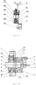
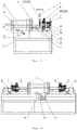
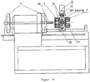
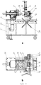
- the present invention also provides an apparatus for rolling external pipe thread, which comprises at least one of the above-mentioned rolling modules, and also includes the base, power motors, clamping device, a power motor control device and a transmission device, the base is provided with the power motor, a power motor control device , the clamping device and the rolling module, the power motor is connected with the clamping device through the transmission device, and under the control of the power motor control device, the power motor promotes the rotation of the hollow blank clamped by the clamping device through the transmission device, thereby generating relative rolling rotational motion with the rolling module.
- the an external pipe thread rolling apparatus comprises at least one of the rolling modules mentioned above , it also includes a base, power motors, clamping device, a power motor control device and a transmission device, the base is provided with the power motor, a power motor control device the clamping device and the rolling module, the power motor is connected with the rolling module through the transmission device; under the control of the power motor control device, the power motor promotes the rotation of the first rolling wheel and or the second rolling wheel in the rolling module through the transmission device, thereby generating relative rolling rotational motion with the hollow blank clamped by the clamping device.
- the clamping device may include a power device, a first clamping die seat, a first clamping die, a second clamping die, and a clamping frame; the power device is cooperatively connected with the first clamping die seat; the first clamping die is installed and fixed on the first clamping die seat; the power device, the first clamping die seat and the first clamping die are installed on one side of the clamping frame; the second clamping die is installed on the other side of the clamping frame; and the first clamping die and the second clamping die are respectively provided with a first semi-cylindrical inner cavity and a second semi-cylindrical inner cavity at opposite positions, preferably, the inner surfaces of the first and second semi-cylindrical lumens each have at least two convex circular arcuate bodies, and the arc of the circular arcuate bodies substantially coincides with the arc of the pre-clamped hollow blank; under the action of the power device, the first clamping die seat can drive the first clamping die to move and make it close to the second clamp
- the invention further provides a hollow blank clamping device, which comprises a power device, a first clamping die seat, a first clamping die, a second clamping die and a clamping frame.
- the power device is cooperatively connected with the first clamping die seat; the first clamping die is installed and fixed on the first clamping die seat; the power device, the first clamping die seat and the first clamping die are installed on one side of the clamping frame; the second clamping die is installed on the other side of the clamping frame; and the first clamping die and the second clamping die are respectively provided with a first semi-cylindrical inner cavity and a second semi-cylindrical inner cavity at opposite positions, preferably, the inner surfaces of the first and second semi-cylindrical lumens each have at least two convex circular arcuate bodies, and the arc of the circular arcuate bodies substantially coincides with the arc of the hollow blank to be clamped; under the action of the power device, the first clamping die seat can drive the first clamping die
- the second clamping die is fixedly engaged with the clamping frame or is provided with a moving engagement with the first clamping die to form a radial movement of the second clamping die and the first clamping die.
- the power device is a hydraulic device
- the first clamping die and the second clamping die are molding materials.
- the present invention also provides a production line for pipe external thread which comprises at least one of the above-mentioned rolling modules, the first rolling head and the second rolling head are respectively mounted on independent rolling devices thereof.
- the first rolling head and the second rolling head are used to roll the hollow blank sequentially.
- Japanese Patent JP6039470 discloses a rolling pre-preparation process which rolls a double conical surface on a hollow cylindrical blank and at the same time cut the workpiece.
- Chinese patent CN102423789A discloses a rolling pre-preparation process of a radial rolling diameter reduction.
- the problems to be solved by the above two patents are merely the formation of the conical surface of the hollow blank or the diameter reduction of the hollow blank, which does not solve the problem of non-roundness, which is crucial for the subsequent rolling.
- the present invention discloses the successive causalities between the port outer diameter, the taper and the length of the hollow blank formed by pre-rolling, and the depth of thread, the thread profile as well as the subsequent thread profile, the length precision and the depth of thread of the pre-formed thread, which explained the dialectical relationship of the cause and the effect between these two processes , and creatively adopts the concept of pre-formed thread, it provides that the pitch of the pre-formed thread is equal to the pitch of thread on external pipe thread forming portion, preferably, the tooth profile of the pre-formed thread does not exceed the tooth profile of the external pipe thread forming portion, and more preferably, the pre-formed thread is a sinusoidal thread, and the relationship between the profile of the pre-formed thread and the life of the rolling wheel. Combined with the unique idea that the number of the rolling wheels in the two rolling processes is odd-even different, especial preferably, the unique idea that the number of pre-forming rolling wheels is greater than the number of pipe thread rolling wheels.
- the invention has the beneficial effects of relaxing the requirement of non-roundness of the ordinary steel pipe (hollow cylindrical blank) accounting for 95% of the market by the rolling pipe external thread process, omitting the process in stamping cone and the process in external chamfer cutting, so that the material is saved, and it also protected and strengthened the protective layer on the surface of the blank, simplifying the rolling apparatus, and not only realizing the advantages of being compatible with the current pipe external thread processing threading machine used 100% the same processing steps, but also realizing the stable and the real non-cutting rolling processing.
- the process is more environmentally friendly, and the product stress distribution is more reasonable and better quality.
- Term "odd-even different” refers to in any two rolling wheel groups that are connected one after another in the processing order, when the number of rolling wheels contained in one rolling wheel group is an odd number, the number of rolling wheels contained in the other rolling wheel group is an even number
- Non-roundness there is a phenomenon that the outer diameters are not equal in the cross-section of the circular steel pipe, that is, the maximum outer diameter and the minimum outer diameter which are not mutually perpendicular to each other, that is, the absolute value of the difference between the maximum outer diameter and the minimum outer diameter is not-roundness. Due to the presence of non-roundness, the steel pipe (hollow blank) is of actually an irregular polygon.
- inclined plane refers to a plane that has an included angle (spiral rising angle) with the reference horizontal plane from the axis of the rolling wheel.
- the two lines (assumed to be a-line and b-line) of the present invention have angles in the "vertical direction". It can be understood that in the XYZ three-dimensional coordinate system, the plane parallel to the a-line and the b-line is defined as XY plane, then the angle between the two lines (the a-line and the -line) formed when the a-line and the b-line are projected along the Z axis in the XY plane is the angle at which the a-line and the b-line exist in the "vertical direction".
- the axis of the rolling wheel and the axis of the hollow workpiece to be machined have a deflection angle of not more than 9 degrees in the vertical direction.
- the plane parallel to the axis of the rolling wheel and the axis of the hollow blank to be processed is defined as the XY plane.
- the angle formed by the two lines of the axis of the rolling wheel and the axis of the hollow blank to be processed being projected along the Z axis on the XY plane is not greater than 9 degrees in the XYZ three-dimensional coordinate system.
- Thread length accuracy make the standard ring gauge and pipe threads to be tested tightly engaged, and examine the parallelism of the thread port and the first, second or third step plane of the ring gauge, wherein being parallel with the second step it is standard thread length accuracy, parallel with the first step it is upper limit of the standard thread length accuracy, and parallel with the third step it is the lower limit of the standard thread length accuracy.
- Hollow blanks according to the present invention are hollow blanks that can be cold formed, including not only metal pipes such as steel pipes, aluminum pipes and copper pipes, but also metal workpieces having a hollow tubular portion structure such as the pipe joint, tee, and it is also possible to include other plastic pipes or workpieces of similar shape that can be cold formed.
- the external pipe thread according to the present invention refers to an existing national standard or an international standard or an enterprise standard or an external pipe thread with practical use function.
- the pre-formed pipe thread of the present invention refers to whose thread pitch same as that of the external pipe thread to be processed, and its depth of thread smaller than that of the external pipe thread.
- the external pipe thread forming portion refers to the section whose threads are corresponding to the external pipe thread to be processed, and the shape, pitch, depth of thread and tooth profile of the thread are all consistent with the external pipe thread to be processed, and the external pipe thread can be formed on the blank by the rolling wheel having the external pipe thread forming portion, as will be easily understood by the prior art person.
- the pre-formed rolling according to the present invention refers to the process of rolling a cylindrical surface or conical surface or a cylindrical conical mixing surface with a pipe thread which is rolled on the hollow blank by the rolling wheel with pre-formed pipe thread on its surface, whether an annular rolling wheel or a thread rolling wheel.
- cylindrical surface with pipe threads or the conical surface with pipe threads or the cylindrical conical mixing surface with pipe threads are not surfaces in the strict sense, but a surface with special pipe 20% cylindrical surface or a conical surface or a cylindrical conical mixing surface, and the shape of the surface threads matches the pipe threads on the pre-formed rolling wheel; only when the depth of thread of the pre-formed thread is zero , the cylindrical surface having a pipe thread or a conical surface having a pipe thread or a cylindrical conical mixing surface having a pipe thread is a smooth surface.
- the pre-formed pipe thread is a rolled non-standard pipe thread
- its profile should not only be based on the external thread profile of the subsequent pipe, but also according to the wall thickness, caliber, material, non-roundness and service life of the rolling wheel of the hollow blank, it is different from the traditional pipe thread used for transmission or sealing or fastening purposes, and it is not designed to solve the problems of sticking, slipping, leaking or tensile failure.
- the depth of thread of the outer surface thread of the pre-formed pipe thread is smaller than the depth of thread of the external pipe thread forming portion, further, the tooth profile of the pre-formed thread does not exceed the tooth profile of the external pipe thread forming portion, and further, the pre-formed thread is a sinusoidal thread.
- the surface roughness Ra of the thread on the outer surface is less than 0.125, the surface hardness is increased by 20% to 100%, and the non-roundness is reduced by 10% to 50%; particularly for the galvanized pipe, the surface zinc layer is intact after pre-formed rolling.
- cylindrical conical mixing surface refers to the outer surface of the hollow blank comprising both the cylindrical surface and the conical surface, or it can be understood as the outer surface composed of one or more cylindrical surfaces and one or more conical surfaces.
- the external pipe thread rolling of the present invention refers to the process of rolling out the cylindrical or conical or cylindrical conical mixing surface on the hollow blank by the rolling wheel.
- the rolling process by the "first rolling wheel group” or the “first rolling head” is also referred to as “pre-forming rolling” or the “first rolling wheel group” is referred to as a" pre-forming rolling wheel group” and a “first rolling head” is referred to as a “pre-forming rolling head”
- the rolling process by the "second rolling wheel group” or “second rolling head” is referred to as "pipe thread forming rolling”
- “second rolling wheel group” is referred to as” pipe thread forming rolling wheel group”
- second rolling head is referred to as "pipe thread forming rolling head”.
- the structure of the pre-forming rolling head of the present invention may be the same as or similar to the structure of the pipe rolling head of the present invention.
- the rolling wheel group according to the present invention refers to a combination of a plurality of rolling wheels used in the same rolling process.
- the specific setting methods of these rolling wheels in the rolling process can be set by techniques well known to those skilled in the art (for example "Thread Processing", edited by Wang Xiangkui, Mechanical Industry Press, 2008). Therefore, the method of the present invention is not limited to certain specific rolling apparatus.
- the rolling head according to the invention refers to a device for rolling on a hollow blank to form intermediate blank and pipe thread products suitable for further processing of the external pipe thread.
- Main body of the device comprises several rolling wheels and rolling wheel seat for supporting or fixing the rolling wheel.
- the rolling wheel cooperates with the rolling wheel seat through a rolling wheel axle and is distributed in a radial direction about the hollow blank.
- a plurality of rolling wheel seats is integrally formed in the same wheel structure to form a rolling wheel disc.
- the rolling process module of the present invention refers to a combination of a plurality of rolling heads or a combination of a plurality of rolling heads and other processing tools.
- Each rolling head may be completely independent or may be disposed in an integral structure.
- Said other processing tools include taper cutting tool, the correction tool for the inner chamber of blank, the chamfering cutting tools inside and outside end mouth, and thread surface processing tools.
- the term “rolling along axial radial mixed direction” or “axially radially mixed rolling” means that the relative movement between the rolling wheel and the blank during the rolling process includes the axial and radial directions movement at the same time, and the relative movement is the relative axial movement of the rolling wheel and the hollow cylindrical blank caused by the axial component, which is generated by the spiral rising angle of the rolling wheel on the hollow blank or the deviation angle in vertical deflection between the axis line of the rolling wheel and the axis line of the hollow cylindrical blank when the rolling wheel is engaged with and rotated relative the hollow cylindrical blank, while the rolling wheel is radial fed according to certain process requirements to complete the rolling process.
- the relative movement speed in the radial direction is zero, i.e.
- the "inner side of the hollow blank” and the “end of the hollow blank” described in the present invention can be understood as the position corresponding to the thread tail and the thread head in the portion to be processed with external pipe thread.
- Completing the axial rolling from the inner side of the hollow blank to the end of the hollow blank can be understood as completing the axial rolling from the corresponding position of the thread tail to the corresponding position of the thread head.
- Pre-rolling in the axial radial mixing direction using this method may be referenced to the method of the external pipe thread shown in the patent WO2014161447A1 .
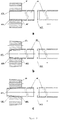
- Fig. 1 shows an existing rolling process schematic view.
- the hollow blank 40 is first axially punched into a conical surface 425 by a taper punching die 13 before performing the thread rolling.
- the cutting tool 91 in the axial cutting device 9 cuts the entire conical surface 425, and then shown as Fig.1c using the rolling wheel 80 to perform thread rolling process of the hollow blank 46 containing the conical surface 425;
- Fig. 1a requires using taper mold machinery (or hydraulic) to axially move and punch workpiece. Firstly, it is processed to form a conical surface, and then the conical pipe thread is formed in the conical surface through rolling, otherwise, the pipe thread tooth is incomplete, and the body of the pipe is easy to crack.
- taper mold machinery or hydraulic
- Fig. 1b has a defect in the cutting process, so we will not repeat here.
- the external pipe thread forming rolling process of the present invention comprises two basic steps of pre-forming rolling and pipe thread forming rolling, that is, the pre-forming thread rolling is performed on a hollow blank by using a pre-forming rolling wheel, and then use the external pipe thread forming rolling wheel to perform further thread forming rolling process of the hollow blank that its non-roundness, the outer diameter of the port, the taper, depth of thread, depth of thread and the axial length both conforms with rolling requirements, and during the process, the number of pre-forming rolling wheels and the number of external pipe thread forming rolling wheels must be odd-even different.
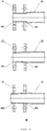
- Figs. 2 to 4 respectively show three pre-forming rolling process embodiments of the present invention.
- Fig. 2 shows an embodiment of a radial pre-forming rolling process according to the invention.
- the rolling wheel 81 completes the pre-forming rolling of the cylindrical surface 424 ( Fig. 2a ) and the conical surface 425 ( Fig. 2b ) by gradually increasing the rolling pressure with radial feed.
- the rolling wheel is designed as a conical cylinder mixture
- the pre-formed hollow blank is also a conical cylinder mixture. Because of its rolling method and the existing radial rolling thread process is similar, which are not repeated here. After pre-rolling the outer surface of the hollow blank has a pre-formed thread.
- the pre-forming process of the present invention preferably adopts an axial pre-forming rolling process.
- Fig. 3 shows an embodiment of the axial pre-forming rolling process of the present invention.
- the pre-forming rolling wheel 81 is a pre-forming threaded cylindrical rolling wheel, and a radial offset angle is provided between the rolling wheel 81 and the hollow blank.
- at least three cylindrical rolling wheels perform cylindrical surface rolling on the outer surface of the hollow blank, preferably, including at least four cylindrical rolling wheels perform cylindrical surface rolling on the outer surface of the hollow blank.
- the rolling of the cylindrical surface means that the outer surface of the rolled hollow blank is a cylindrical surface 424.
- the pre-forming rolling wheel 81 when the pre-forming rolling wheel 81 is a conical pre-forming threaded rolling wheel, at least three conical rolling wheels perform conical surface rolling on the outer surface of the hollow blank, preferably, including at least four conical rolling wheels perform conical surface rolling on the outer surface of the hollow blank, and the conical rolling means the outer surface of the hollow blank is a conical surface 425.
- the port of the hollow blank axially exceeds the conical rolling wheel 81, the exceeded portion is a cylindrical portion, and a hollow blank which have been rolled through a pre-forming rolling has a cylindrical conical mixing surface, after pre-rolling the outer surface of the hollow blank has a pre-formed thread.
- the pre-forming rolling wheel when the pre-forming rolling wheel having pre-forming thread its depth of thread is zero, the pre-forming rolling wheel is the smooth pre-forming rolling wheel.
- the smooth rolling wheel is changed into an annular rolling wheel with a certain pitch; the size of the pitch depends in part on value of the radial offset angle ⁇ .
- the radial offset angle ⁇ causes the hollow blank to rotate in contact with the rolling wheel at 400, resulting in an axial relative movement between the two, completing the axial pre-forming rolling at 401, which changes a technical bias that the smooth rolling wheel only can be used for radial feed rolling.
- the pitch of the pre-formed thread must be consistent with the pitch of the external pipe thread. When the preformed rolling adopts a smooth rolling wheel, the pitch of the pre-formed thread is a special pitch, which can also be considered to be consistent with the pitch of the external pipe thread.
- an axial radial pre-forming rolling process is preferably employed.
- Fig. 4 shows an embodiment of an axial radial mixing pre-forming rolling process according to the present invention, in which the pre-forming rolling wheel 81 is a pre-forming threaded cylindrical rolling wheel ( Fig. 4a ) or a pre-forming threaded conical rolling wheel ( Fig. 4b ), and the effective length of the rolling wheel is less than the thread length of the pipe external thread product to be processed.
- a radial offset angle is provided between the rolling wheel 81 and the hollow blank.
- the rolling wheel 81 moves axially from the inner side 400 of the hollow blank to the end 401 of the hollow blank, while the rolling wheel 81 is radially fed to a certain process position to remain unchanged or to be synchronized with the radial feed to a certain process position to remain unchanged, so that outer surface of part of the hollow blank to be provided with thread were processed into a threaded cylindrical surface ( Fig. 4a ) or conical threaded surface ( Fig. 4b ) or threaded cylindrical conical mixing surface ( Fig. 4c ).
- the pitch of the pre-formed thread is equal to the pitch of thread on external pipe thread forming portion
- the pitch of the pre-formed thread on the preformed rolling wheel forming the various surfaces described above is equal to the pitch of thread on the external pipe thread to be rolled subsequently
- the depth of thread of the pre-formed thread is smaller than the depth of thread of the external pipe thread to be rolled subsequently
- the pre-formed thread can be provided as follows: Depth of thread: when used for rolling the cylindrical external pipe thread, the depth of thread of the pre-formed blank is 5% to 70% the depth of thread of the cylindrical pipe thread to be processed, preferably 5% to 40%.
- the depth of thread of the pre-formed blank is equal to 5% -60% the depth of thread of the tapered pipe thread to be processed, preferably 10% to 40%.
- the tooth profile of the pre-formed thread does not exceed the tooth profile of the external pipe thread forming portion.
- Tooth profile preferably, the pre-formed thread profile is a sinusoidal thread profile.
- the taper of the pre-forming thread is zero; for rolling the external pipe thread on the conical surface the taper of the pre-forming thread is generally from 2° to 12°, preferably from 3°30 "to 8°30".
- Axial length it is to be noted that the length after being pre-formed rolling, the threaded cylindrical or the threaded conical surface or the threaded cylindrical conical mixing surface should be greater than or equal to the length of the subsequent thread product, preferably 1 to 3 pitch, particularly preferably by 2 pitch.
- the pre-formed thread has formed on the blank section that is to be provided with the thread, the stress is partially released, and the non-roundness of the blank reaches the requirement of subsequent rolling pipe thread, and the port diameter, taper and length (or height) of the cylindrical and conical surface is more suitable for subsequent pipe thread forming rolling, which is essential for the next step of the pipe thread forming rolling.
- the shape of the pre-forming rolling wheel of the present invention is not limited to three types of cylindrical rolling wheel, conical rolling wheel and conical cylindrical mixing wheel.
- the cylindrical rolling wheel and the conical rolling wheel may not only be the rolling wheel with thread outside surface, but also rolling wheel with smooth outer surface when the thread depth of thread is zero, and can be mixed rolling wheel with threads on the outer surface and smooth surface.
- the pre-forming rolling wheel can be an annular rolling wheel and can also be a spiral rolling wheel.
- the axis of the pre-forming rolling wheel in order to be able to automatically feed the hollow blank in the pre-forming rolling step, has a certain deflection angle in vertical deviation from the axis of the hollow blank. The deflection angle is equal to spiral rising angle of the pre-formed pipe thread.
- the pre-formed rolling wheel of the present invention utilizes a conical rolling wheel with a smooth surface, and in order to be able to automatically feed the hollow blank in the pre-forming rolling step, the axis of the pre-forming rolling wheel has a certain deflection angle in vertical deviation from the axis of the hollow blank.
- the axial feed for the pre-forming rolling is accomplished by an axial force incurred by the deflection angle.
- the phenomenon of difficulty in feeding the blank and the failure in operation may occur, which will affect the processability of the device.
- it can be added the cutting outside chamfering process, but the steel pipe blank with 1.5 pitch or so at the port is thinned and the zinc player on the surface is destroyed.
- the preformed rolling is preferably use a surface having a pre-formed thread with the depth of thread that is not zero, the depth of thread of the outer surface thread is smaller than the depth of thread of the external pipe thread forming portion, and more preferably, the tooth profile of the pre-formed thread does not exceed the tooth profile of the external pipe thread forming portion, and more preferably, the pre-formed thread is a sinusoidal thread.
- the pre-forming rolling process of the invention can only use a group of pre-forming rolling wheels to perform pre-forming rolling, and can also use a plurality of groups of pre-forming rolling wheels to repeatedly perform pre-forming rolling of the blank. After repeated pre-rolling, the hollow blank is processed with thread rolling in accordance with the spirit of the present invention, so as to form the external pipe thread.
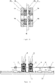
- Fig. 5 is a schematic view of the process of the present invention for further axial rolling to form a pipe external thread on a pre-rolled hollow blank.
- the pipe thread forming rolling wheel of the present invention comprises an external pipe thread forming portion through which a desired external pipe thread can be formed on a pre-rolled hollow blank.
- the external pipe thread rolling process of the present invention can be understood as according to the outer diameter, the wall thickness , non-roundness and the material of the hollow blank, the subsequent pipe thread profile and the thread length accuracy, the pre-forming rolling of the portion of the hollow blank to be processed with the pipe thread is firstly performed either in the axial or axial radial direction, as that the same thread pitch and the different depth of thread between the front and rear pre-formed rolling thread and the external pipe thread, controlling the depth of thread of the pre-form pipe thread purposefully, in one embodiment, the depth of thread of the external pipe thread of the national standard 55° DN20 is 1.162 mm, and the depth of thread of the pre-form thread is taken to be 0.4 mm, but the thread pitch is the same, which is actually a special spiral line.
- the depth of thread of the outer surface thread is smaller than the depth of thread of the external pipe thread forming portion, further, the tooth profile of the pre-formed thread does not exceed the tooth profile of the external pipe thread forming portion, and more preferably, the pre-formed thread is a sinusoidal thread.
- the original residual curvature range of the hollow blank (steel pipe) is gradually reduced and partial residual stress of the hollow blank is gradually released, so that the cross-section of the rolled portion of the hollow blank is formed by rolling from the original random polygons into a cylindrical or conical or cylindrical conical mixture that still has a certain ellipticity and can be controlled, the regular blank conforms to the subsequent thread rolling requirements. and it is found that according to the non-roundness of different original blanks, the non-roundness of original blanks can be reduced by about 10% to 35% after pre-formed rolling.
- an axial rolling or axial radial mixing rolling In order to reduce the radial force of the apparatus during pre-forming rolling, it is preferable to use an axial rolling or axial radial mixing rolling; further to reduce the subversion torque of the apparatus during pre-forming rolling, an axial radial mixing rolling is preferably used. On this basis, it is further motivated to make use of the principle of the number of pipe thread forming rolling wheels matching with the even and odd numbers different in number of the pre-formed rolling wheel, wherein a plurality of spiral lines of controlled length are formed and the residual stress of the hollow blank is released to correct the non-roundness of the blank.
- the number of rolling wheels in two adjacent rolling steps must be different; that is, in the embodiment with two different process steps of pre-forming rolling and pipe thread forming rolling, the number of rolling wheels for pre-forming rolling and the number of rolling wheels for pipe thread forming rolling must be odd-even different.
- the number of rolling wheels for the pre-forming rolling process is an odd number
- the number of rolling wheels in the adjacent pipe thread forming rolling process must be an even number
- the number of rolling wheels for the pre-forming rolling process is even
- the number of rolling wheels in the adjacent pipe thread forming rolling process must be an odd number.
- even and odd numbers matching it can significantly improve the yield of pipe thread forming rolling products by effectively controlling the depth of thread of the pre-formed thread and the thread profile, the pre-formed blank port outer diameter, taper and axial length.
- the number of the pre-rolling wheels for correction of the present invention is at least three, and the number of pipe thread forming rolling wheels for pipe thread forming rolling is also at least two , particularly preferably, the number of the pre-rolling wheels for correction is greater than or equal to 4, the number of the pipe thread forming rolling wheels is greater than or equal to 3, and the number of the pre-forming rolling wheels is greater than that of the pipe thread forming rolling wheels.
- the length of the pre-forming rolling wheel must be greater than or equal to that of the pipe thread product, preferably a pitch of 1 to 3 teeth larger.
- pre-rolling process in the pipe thread forming rolling process may be implemented by one pre-rolling or may be achieved by multiple rolling operations, for example, performing firstly, secondly, thirdly correcting pre-rolling, and then performing the pipe thread forming rolling, but the number of rolling wheels at two adjacent rolling steps must be different.
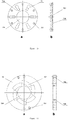
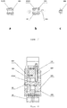
- Fig. 6 shows a schematic view of a pre-forming rolling head with only one rolling wheel disc 60 according to the present invention.
- the number of pre-forming rolling wheels 81 is five, and the five pre-forming rolling wheels are equally distributed around the processing axils of the hollow blank.
- the rolling head is rotated by the power motor via the pin shaft 67, to form a structure of the rolling wheel 81 around the rolling wheel axle 83.
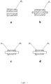
- Fig. 7 shows an embodiment of a plurality of pre-forming rolling wheels of the present invention.
- the pre-forming rolling wheel of the present invention may be a threaded conical rolling wheel (7a), a cylindrical rolling wheel (7b) with a smooth annular rolling wheel and a rolling wheel shaft formed together, a cylindrical rolling wheel (7c) in combination with cutting tools and a cylindrical rolling wheel (7d) which are integrally provided with the cutting tools, and so on.
- the hollow blank can be formed with the desired threaded cylindrical or threaded conical surface or threaded cylindrical conical mixing surface at the same time to complete the hollow blank cutting, greatly improving the external pipe thread processing effectiveness.
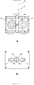
- Figure 8 shows a schematic view of a rolling head for forming pipe thread of the present invention, which includes a radial adjustment disc 76 and a rolling wheel 70 and corresponds to Figure 6 , comprising four pipe thread forming rolling wheels 82.
- the four pipe thread forming rolling wheels are equally distributed in the hollow blank around the processing axis.
- the rolling head is rotated by the power motor via the pin shaft 67 to form a structure of the rolling wheel 81 around the rolling wheel axle 83.
- the number of pre-forming rolling wheels is four, and the number of pipe thread forming rolling wheels is three.
- the number of pre-forming rolling wheels is six, and the number of pipe thread forming rolling wheels is three or five.
- the number of pre-forming rolling wheels is seven, and the number of pipe thread forming rolling wheels is four or six.
- the number of pre-forming rolling wheels is eight, and the number of pipe thread forming rolling wheels is five or seven.
- the number of pre-forming rolling wheels is nine, and the number of pipe thread forming rolling wheels is four, six or eight.
- the number of pre-forming rolling wheels and the number of pipe thread forming rolling wheels do not generally exceed 15, preferably 4, 5, 6, 7, 8 or 9;
- the number of pre-forming rolling wheels and the number of pipe thread forming rolling wheels do not generally exceed 19, preferably 4, 5, 6, 7, 8, 9, 10 or 11;
- the number of pre-forming rolling wheels and the number of pipe thread forming rolling wheels do not exceed 35, preferably 4, 5, 6, 7, 8, 9, 10 , 11, 12, 13, 14, 15, 16, 17, 18, 19 or 20.
- the number of pre-forming rolling wheels and the number of pipe thread forming rolling wheels vary from 1 to 11, preferably 1, 3, 5 or 7.
- the different numbers may be the number that the number of the pre-forming rolling wheels is more or less than the number of the pipe thread forming rolling wheels. It is preferable that the number of the pre-forming rolling wheels is more, so as to reduce the number of pipe thread forming rolling wheels and thereby reduce the difficulty of teeth alignment during pipe thread rolling.
- the number, the taper and the length of the pre-forming rolling wheels, and the number of pipe thread forming rolling wheels, the length accuracy of the pipe thread products can be increased, decreased or matched according to the outer diameter, the wall thickness and the material, non-roundness of the hollow blank, rolling wheel diameter size, rolling wheel form, thread profile and rolling thread length accuracy requirements, and so on.
- the form of the pre-forming rolling wheels and the pipe thread forming rolling wheels is preferably a structure in which the rolling wheel and the rolling wheel shaft are integrated. In this way, the number of rolling wheels can be effectively increased, which is beneficial to reducing the times of rolling in stages and prolonging the life of the rolling wheel.
- a preferable pre-forming rolling and pipe thread forming rolling head there is an axially free movable space 891 ( Figs. 6b and 8b ) between the rolling wheel and the rolling wheel seat, of course there is a certain radial movable space 892 ( Figs. 6b and 8b ).
- the movable space means that there is a space for the rolling wheel to move freely in the space.
- the axial movable space refers to the movable space of the rolling wheel in the axial direction of the rolling wheel axle.
- the axial distance of the axial movable space refers to the maximum distance at which the rolling wheel is freely movable in the axial direction of the rolling wheel shaft.
- the radial movable space refers to the movable space of the rolling wheel movable in the vertical direction of the processing axils along the hollow blank, and the radial distance of the radial movable space refers to the maximum distance of the pipe thread forming portion of the rolling wheel free movable in the vertical direction of the processing axis of the hollow blank relative to the hollow blank to be processed.
- the rolling wheel and the rolling wheel seat or the rolling wheel axle and the rolling wheel seat may be a shaft hole free movable cooperation.
- Figs. 6b and 8b shows this type of cooperation, wherein Fig. 6b is a schematic structural view showing a pipe thread forming rolling head which only comprises a rolling wheel disc, wherein the rolling wheel and the rolling wheel shaft are integrated;
- Fig. 8b shows a schematic structural view of a pre-forming rolling head including a rolling wheel disc and a adjusting disc.
- the rolling wheel and the rolling wheel shaft are capable of freely cooperating with each other and show the free cooperation schematic view of the rolling wheel and the rolling wheel seat.
- the pre-forming rolling wheel or the forming rolling wheel for forming pipe thread of the present invention may be an annular rolling wheel or a thread rolling wheel, and preferably an annular rolling wheel, the external thread forming rolling wheel adopts a thread rolling wheel.
- the rolling wheel adopts an annular rolling wheel
- the axis of rolling wheel and the axis of the workpiece processing working hole have a deflection angle of not more than 9 degrees in the vertical direction; meanwhile, in order to make each annular rolling wheel in the floating space to achieve automatic teeth alignment in the most economical way, reduce injury of non-roundness by the rolling pressure on the hollow blank, the rolling wheel for forming pipe thread and its rolling wheel seat or rolling wheel shaft for forming pipe thread and the rolling wheel seat can be a shaft hole cooperation with clearance for free movement; and each annual rolling wheel has surface provided with initial part of the thread.
- the initial part of the thread refers to thread that firstly contacts the hollow blank when the annual rolling wheel performs the thread rolling process, preferably the initial part of the thread with an equal extension or bisecting indent design, and the specific design idea is as follows: It is assumed that the rolling head for forming pipe thread comprises a total of N annular rolling wheels, starting from one of the annular rolling wheels Ri and the initial part of the thread of the next rolling wheel Ri + 1 in the same clockwise direction is: a thread obtained based on the initial part of the thread of the rolling wheel Ri to extend a distance of 1 / N pitch in accordance with the original thread form and the pitch in the direction of the axis of the rolling wheel Ri.
- Fig. 9 shows the position distribution of the initial part threads 821, 822, 823 and 824 of the respective annular rolling wheels in the rolling head for forming pipe thread including four annual rolling wheels according to the present invention.
- each annular rolling wheel is arranged in a row from left to right according to the order of clockwise arranged in the rolling head for forming pipe thread.
- the initial part thread 821 of the annular rolling wheel R l is shown as a complete annual threads starting from the bottom of the tooth;
- the initial portion thread 822 of the rolling wheel R2 is a thread obtained by extending the initial portion thread 821 of the rolling wheel R1 by a distance of 1/4 pitch in the axial direction of the rolling wheel R1;
- the initial portion thread 823 of the rolling wheel R3 is a thread obtained by extending the initial portion thread 822 of the rolling wheel R2 by a distance of 1/4 pitch in the axial direction of the rolling wheel R2;
- the starting portion thread 824 of the rolling wheel R4 is a thread obtained by extending the initial portion thread 823 of the rolling wheel R3 by a distance of 1/4 pitch in the axial direction of the rolling wheel R3;
- a starting portion thread 821 of the rolling wheel R1 is a thread obtained by extending the initial portion
- the pre-forming rolling head and the rolling head for forming pipe thread according to the present invention may adopt the same or similar structural design.
- both the pre-forming rolling head and the rolling head for forming pipe thread can adopt a structural design with a rolling wheel disc and an adjusting disc or a structural design with only a rolling wheel disc.
- Figs. 10 to 16 describe in detail an embodiment of a universal rolling head structure of the present invention.
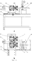
- Fig. 10 is a schematic structural view of an embodiment of an axially rolling head according to the present invention.
- Fig. 11 is a schematic view of the structure of a rolling wheel with six rolling wheels in the rolling head of Fig. 10 .
- Fig. 11a is a front view of the rolling wheel disc
- Fig. 11b is a side view of the rolling wheel disc. As shown in Figs.
- the rolling head comprises front and rear rolling wheel discs (70A, 70B), a rolling wheel shaft 83 matched with the radial groove 71 on the rolling wheel disc and rolling wheel 8 thereof, and a connecting pin shaft 702 matched with the pin hole 701 on the rolling wheel disc; a workpiece processing hole 704 at the center of the rolling wheel disc, and the mounting surface of the radial groove 71 of the rolling wheel disc to the rolling wheel is an inclined plane 703; the rolling wheel shaft 83 is mounted on the radial groove 71 of rolling wheel by two end inclined planes 832a and 832b matched with the radial grooves 71 on the rolling wheel disc, and the shape and size of the groove 71 allows the rolling wheel axle 83 to be axially mounted.
- the two rolling wheel discs 70A and 70B are connected and fixed with each other through the connecting pin shaft 702 of the rolling wheel to form the rolling head coaxially.
- a rolling time and position control adjustment rod 121 is provided at the end of the rolling head for controlling the pre-forming rolling time and the rolling axial length.
- Fig. 12 is a three-dimensional view of the structure of the rolling wheel axle in the rolling head of Fig. 10 and a schematic view of the radial offset angle ⁇ in the vertical direction of the rolling wheel axle and the hollow cylindrical blank body shaft.
- Fig. 12a is a front view of the rolling wheel shaft
- Fig. 12b is a top view of the rolling wheel shaft
- Fig. 12c is a side view of the rolling axle.
- the two ends of the rolling wheel shaft 83 each have upper and lower inclined planes 832a and 832b parallel to each other.
- the axis x' of the inclined plane and the axial center line x of the rolling wheel shaft form a radial setting angle ⁇ .
- the axis of the machining center is parallel to x 'and the angle between x and the plane formed by the machining center axis and x' is equal to the radial setting angle ⁇ .
- Fig. 12d clearly shows that when the rolling wheel is coaxially mounted on the center of the rolling wheel shaft, the rolling wheel axle line forms a radial set angle ⁇ with the inclined planes 832a, 832b.
- the shaft of the rolling wheel which installed and the axial of the hollow blank forms a spiral rising angle ⁇ , and when the hollow blank and the rolling wheel make mutual contact with each other, the hollow blank can be moved axially.
- the radial setting angle ⁇ is preferably less than 5 degrees for steel pipes below 2 inches; and the radial setting angle ⁇ is preferably less than 3 degrees for 2 to 6 inches.
- Fig.12e is a front view of the rolling wheel axle
- Fig.12f is a plan view of the rolling wheel axle
- Fig.12g is a side view of the rolling wheel axle.
- Fig.12h clearly shows that when the rolling is mounted concentrically in the center of the rolling axle, the rolling axle line and the planes 832a, 832b form a radial set angle of 0. Others are similar to those of Figs.12a, 12b, 12c and 12d , and will not be described again.
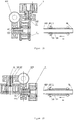
- Fig. 13 is a rolling head embodiment further comprising an axial rolling of the adjusting disk on the basis of Fig. 10 according to the present invention.
- Fig. 14 is a structural diagram of the rolling wheel in Fig. 13 .
- Fig. 14a is a front view of the rolling wheel disc
- Fig. 14b is a side view of the rolling wheel disc.
- the rolling wheel of Fig. 14 is basically similar in structure to the rolling wheel of Fig. 11 , except that the shape of the radial groove 71 is the same.
- the radial groove 71 of the rolling wheel in Fig. 14 is a combination of a cylinder and a cuboid.
- the cylinder exists for the purpose of mounting the rolling wheel shaft with a cylindrical end.
- the radial groove 71 of the rolling wheel in Fig. 11 is an approximately rectangular structure, cooperating with the rolling wheel shaft with an approximating rectangular end. Other structures are the same, which will not be repeated here.
- Fig. 15 is a schematic structural view of the adjusting disc in the rolling head of Fig. 13 .
- Fig. 15a is a front view of the adjusting disc structure
- Fig. 15b is a side view of the adjusting disc structure.
- the radial adjusting device comprises a front and back adjusting disc 76A and 76B and a fixed connecting pin 763 matched with the pin hole 761 on the adjusting disc.
- the center of the adjusting disc is provided with a workpiece processing working hole 764 matched with the rolling wheel disc and a positioning hole 766 for positioning the adjusting disc which is matched with the rolling wheel disc;
- the adjusting disc 76 is coaxially mounted front and rear respectively on the outside of the rolling wheel disc through the positioning blind hole 766 of the adjusting disc and are connected to each other by the adjusting disc pin 763 and to form a shaft hole with the adjusting disc pin; As shown in Fig.
- a sliding block 836 is mounted on the two ends 836 of the rolling wheel axel and slides in the arc-shape groove 762 of the adjusting disc, so that the rolling wheel axle 83 moves radially in the radial groove 71 of the rolling wheel 70 to form a rolling head whose radial position is adjustable with respect to the rolling wheel.
- a rolling position photo-sensing control adjustment rod 122 is provided on the side where the rolling head is finished rolling for controlling the rolling time and the rolling length.
- the pre-forming rolling time controlled by the photo induction control adjusting rod 121 in Fig. 10 and the thread rolling time controlled by the control adjusting rod 122 in Fig. 13 must be matched reasonably in order to roll out the qualified pipe external thread product.
- the power motor is rotated by the rolling head driven by the pin 77 so that the rolling wheel 8 surrounds the rolling wheel shaft 83.
- Fig. 16 is a plan view of the structure of the rolling wheel shaft and its radial offset angle according to the present invention.
- Fig. 16a is a front view of the rolling wheel shaft
- Fig. 16b is a top view of the rolling wheel shaft
- Fig. 16c is a side view of the rolling wheel shaft
- Fig. 16d is a schematic view showing the angle ⁇ provided in the vertical direction between the rolling wheel axis and the hollow cylindrical blank axis.
- the rolling wheel is a thread rolling wheel
- the radial setting angle is 0.
- Fig.16e is a front view of the rolling wheel axle
- Fig.16f is a plan view of the rolling wheel axle
- Fig.16g is a side view of the rolling wheel axle.
- Fig.16h clearly shows that when the roller is mounted concentrically in the center of the rolling axle, the roller axle line and the planes 832a, 832b form a radial set angle of 0. Others are similar to those of Figs. 16a, 16b, 16c and 16d , and will not be described again.
- Fig. 17a is a schematic view of the structure of a rolling wheel according to the present invention.
- the rolling wheel includes a guiding-in portion and a rolling portion.
- the taper of the pre-forming rolling portion on the rolling wheel is 2° to12°.
- the taper size of the pre-forming rolling portion is determined according to the essence of the present invention, preferably 3°30 " ⁇ 8°30".
- the angle of the guiding-in can be generally 13°; the rolling portion for pipe thread has a pipe thread taper of 1:16.
- Fig. 17b is a schematic view of the rolling wheel, a needle bearing cooperating with a rolling wheel shaft according to the present invention.
- the cooperation of the rolling wheel 8 and the needle bearing 831 mainly reduces the rotational friction force of the rolling wheel.
- the rolling wheel 8 is freely mounted on the rolling wheel shaft 83 through needle bearings 831.
- the rolling wheel shaft 83 and the rolling wheel 8 can also be matched with each other by balls, aligning or other bearings;
- Fig.17c is a cross-sectional view of a sliding block that mates with a rolling wheel shaft.
- the two cylindrical ends 833 of the rolling wheel shaft 83 are mounted (position adjusting) in the holes of the sliding block 836 to form a shaft hole fitting; the sliding block 836 is installed in the arc-shaped slot 762 of the adjusting disc, forming a cylinder and circular arc cooperation.
- a rolling position control adjustment rod 122 is provided at the end of the rolling head for controlling the rolling time and the rolling length.
- the rolling wheel is movably fixed on the apparatus rack (not shown) by a rolling head frame 68 (as shown in Fig. 18 ).
- the adjusting disc is rotated with respect to the rolling wheel disc.
- a cam device is provided on the adjusting disc (not shown in the Fig.). The cam curve controls the radial distance adjustment of the rolling wheel and the radial opening of the rolling head.
- a detecting device 123 (also not shown in the Fig.) can also be arranged between the rolling wheel disc and the adjusting disc for numerical control purpose.
- Fig. 18 is a rolling head embodiment that can be passed through by the improved hollow blank on the basis of Fig. 13 rolling in the axial direction.
- Pipe thread rolling time control and pre-forming rolling time and rolling wheel radial position must be a reasonable match.
- the length of the pre-forming conical or cylindrical surface or the axial radial mixing surface should be greater than or equal to the length of the pipe thread to be rolled, preferably 1 to 3 teeth, more preferably 2 teeth pitch.
- the setting of the radial position determines the outer diameter of the pre-forming hollow blank end port.
- the frame structure 68 of the rolling head of Fig. 18 has holes (not shown) and pins (not shown) on the side end thereof.
- the frame structure 68 or the side ends of the rolling head are sleeved on the hole of the rolling device sliding frame, forming a floating connection, so as to achieve self-centering of the rolling module seat and the hollow blank.
- the rolling disc 60 and the adjusting disc 66 in Fig. 18 are similar to those of Figs.11 , 14, and 15 , the mounting and setting of the rolling wheel shaft and the rolling wheel are exactly the same as those of 12 and 16, and will not be described again.
- the difference between Fig. 18 and Figs. 6 , 8 , 10 and 13 is that the center of the front rolling disc and the front adjusting disc are not provided with other auxiliary or transmission means, so that the hollow blank can be axially rolled through the rolling head.
- Fig. 19 shows a schematic structural view of an embodiment of a manual axial radial pre-forming rolling head of the present invention.
- the rolling head comprises: an upper rolling wheel base disc 60A2, a threaded upper rolling wheel base pushing rod 60A1, a torque amplifying gear group 69, a lead screw nut 696, a rotating handle 691.
- the upper rolling wheel base disc 60A2 and the rolling wheel seat 60A is fixedly connected and sleeved on the guiding column 611 to form shaft-hole cooperation.
- One end of the upper rolling wheel seat pushing rod 60A1 is against and fixedly to the upper rolling seat disc 60A2, and the other end cooperates with the lead screw nut 696, and cooperates with the output gear bore bearing in the torque amplification gear group coaxially.
- the input shaft of the torque amplifying gear group 69 is fixedly connected with the rotation handle 691.
- the lower rolling wheel base disc 60B2 and the lower rolling wheel seat 60B are fixedly connected and sleeved and fixed on the guide column 611.
- the rotation handle 691 drives the gear input shaft to rotate
- the upper rolling wheel seat post 60A1 is driven to move up and down through the torque amplifying gear group 69 and the screw nut 696.
- the hollow cylindrical blank 40 is engaged and rotated by the rolling wheel 81, the radial rolling of the rolling wheel is completed.
- the rolling wheel 81 is arranged so that its axial direction and the hollow blank have a deflection angle ⁇ in the vertical direction (radial direction), the radial rolling becomes an axial radial mixing rolling.
- the rolling head can also complete the cutting process of the hollow cylindrical blank.
- the rolling head of Fig. 19 has a hole 601 and a number of pins (not shown) on the side end of the frame structure.
- the side end of the rolling head is connected to the hole on the roller carriage by the pins to form a floating connection, thereby achieving self-centering of the rolling module seat and the hollow blank, the pre-formed rolling wheel, preferably, adopts to a pre-formed thread structure.
- the self-centering design of the rolling head and the hollow blank of Figs. 18 , 19 and 20 by the floating connection of the shaft hole clearance between the rolling head and the shaft hole of the base actually solves the problem that the manufacturing and assembling precision of the apparatus and the hollow blank and the concentricity of the actual mounting of the blank, which is also crucial to the rolling.
- the size of the shaft hole clearance depends on the design and manufacturing precision of the device, preferably no more than +/- 1 mm.
- Fig.33a is a schematic view showing the structure of the rolling head for rotating the rolling head by the worm wheel transfer power
- Fig.33b is a schematic view showing the structure of the worm with Fig.33a
- Fig.33c and Fig.33b are further schematic structural views of the adjusting disc.
- the structure of the rolling head in Fig.33a is similar to that of Fig.18 , with first and second rolling plates, connecting pins, and the like.
- the structure of the rolling plate is similar to that of Fig.11 , and the mounting manners of the rolling wheel and the rolling wheel shaft are completely the same as those in Fig.12 and will not be described again.
- the difference is that the center of the front rolling plate is not provided with other auxiliary or transmission means, so that the hollow blank can be axially rolled through the rolling head.
- Fig.33b is a perspective view of the rolling head of Fig.33a including a worm or a gear 731, a power motor control device 21 and a power motor (not shown), one end of which is mechanically coupled to the output shaft of the power motor control device 21, and the other end in mechanical cooperation with the worm wheel or the gear 736, the power motor drives the worm or the gear 731 to rotate by the transmission device 21, and the pulsator or gear 736 drives the rolling wheel 70 to rotate.
- Fig.33c is a view of an embodiment of a rolling head further including the axial rolling of the adjusting disc according to Fig.33b .
- the structure of the adjusting disc is similar to that of Figs.14 and 15 , and the rolling wheel and the rolling wheel axle are mounted. It is exactly the same as Fig.16 and will not be described again. The difference is that the center of the front adjustment disc is not provided with other auxiliary or transmission means, and the hollow blank can be axially rolled through the rolling head.
- Fig.34 is a block diagram showing an embodiment of a rolling head further including the axial rolling of the adjusting disc on the basis of Fig.7 in accordance with the present invention.
- the structure of the rolling head can also be properly arranged and modified according to the corresponding rolling head device involved in the following patents listed as follows: US5699691A , US3058196A , EP282889A2 , US3452567A , US3058196A , US20060162411A1 , JP10034270A , JP10244340A , JP2003126937A , JP9327742A , CN100542735C , CN2555962Y , CN103264128A , CN103286245A , SU1344479A1 , US20120011912A1 , US4617816A , US4785649A , US5870918A , GB1150525A , JP1273637A , SU703197 A1 .
- the pre-forming rolling head and the rolling head for forming pipe thread according to the present invention may be separate or combined into one body. When the two are combined into one, the process can be effectively saved, and the external pipe thread to be processed is formed by rolling sequentially.
- the overall design is more compact and convenient for transportation and installation.
- Fig. 20 shows a schematic view of the structure of a rolling process module in which a pre-forming rolling head 6 and a rolling head 7 for forming pipe thread are combined into one body according to the present invention.
- a pre-forming rolling head 6 with five rolling wheels 81 and on the right-hand a rolling head for forming pipe thread 7 with four rolling wheels 82.
- Structure of the pre-forming rolling head 6 is similar to that of Fig. 18
- the pipe thread forming rolling head 7 adopts a rolling head structure similar to that in Fig. 13 .
- the radial grooves (71) in the rolling heads and the mounting surface of the rolling wheel (8) May be an inclined plane (703) or a conventional plane (as shown in Fig. 6 or Fig. 8 ).
- a relative rotational position angle detecting device 123 is provided between the rolling wheel and the adjusting disc of the pre-forming rolling head 6 and the pipe thread forming rolling head 7, and can be determined according to the variation of the blank diameter, the wall thickness and the materials and actual requirements of the pipe thread products.
- the radial position of the rolling wheel of the pre-forming rolling head should be reduced to no more than 0.5 mm.
- the radial position of the rolling wheel of the pre-forming rolling head should be enlarged by no more than 0.5 mm.
- the length of the pre-forming rolling surface controlled by the rolling time is equal to or greater than that of the pipe thread product, preferably greater by the pitch length of 1 to 3 teeth, more preferably the pitch length of 2 teeth.
- the pre-forming rolling head 6 and the pipe thread forming rolling head 7 are connected with each other by a pin to ensure that the pre-forming rolling head 6 and the pipe thread forming rolling head 7 are disposed coaxially with the hollow blank to be processed.
- the workpiece passes through the pre-forming rolling head, directly into the pipe thread rolling.
- the hollow blank 40 enters the rolling head from the left and number reference 121 and 122 are used to mark the control adjusting rod of the photo-sensing device which controls the pre-forming rolling time and sequence.
- the control adjusting rod 121 drives the photoelectric sensing device to work, and the adjusting disc 66 is started to turn in the reverse direction to disengage the hollow cylindrical blank from rolling wheel 81, to complete the pre-forming rolling and come into the right pipe thread forming rolling process.
- the photoelectric sensor device When its head contact the control adjusting rod 122, the photoelectric sensor device operate and start the adjusting disc 76 to rotate in opposite direction to open, so that the hollow cylindrical blank is disengaged from the rolling wheel 81, to complete the pipe thread rolling, and the process is similar to the foregoing, which are not repeated here.
- Fig. 21 shows a schematic structural view of a single head pre-forming rolling and pipe thread forming rolling apparatus comprising a rolling head shown in Figs. 13 and 18 with hollow blank rotating. Except for the design of the rolling head, the design of the other components is consistent with the single head pipe thread forming rolling device with the hollow blank rotating as disclosed in the patent WO2014056419A1 .
- the main structure includes a base 1, a power motor 22, a work clamping device 3, a power motor control device 20, and a transmission 21 that couples the power motor to the hollow cylinder blank clamping device or the rolling head.
- the base 1 is provided with the power motor 22, the power motor control device 20 and the clamping device 3 for clamping the hollow cylindrical blank to be processed. Under the control of the power motor control device 20, the power motor 22 generates a relative rolling and rotational movement of the hollow blank 40 sandwiched by the rolling wheel and the clamping device 3 through the transmission device 21.
- Fig. 22 is a schematic structural view of a double-headed external pipe thread rolling apparatus which includes two groups of integrated rolling process modules of Fig. 20 .
- Left and right sides in the figure are provided hollow blank pre-forming rolling head 6 and the pipe thread forming rolling head 7.
- the axial and radial mode of operation of the left and right four rolling head, the basic configuration and function of the device is the same as that in Figs. 20 and 21 , which are not repeated here.
- a chamfering device 9 can be provided to complete the chamfer function.
- Figs. 23 ⁇ 31 are distribution structures of four embodiments of the rotary rolling process module according to the present invention.
- the rolling head is driven to rotate by a power (servo) motor, through mechanical transmission such as a reduction gear box, a worm gear and the like.
- a pre-forming rolling head, a pipe thread forming rolling head, and other processing tools such as a nozzle face chamfering machining tool, an inner space correction tool, a taper correction tools and thread surface grinding or heat treatment tools etc., are installed in the rolling head through the keyway 67 or 77 in Fig. 10 or Fig. 13 .
- This processing method that a hollow blank is fixed, and the rolling head rotate is suitable for external pipe thread processing of long pipe, especially, it is very meaningful for the oil casing pipe external thread processing.
- the size control of the hole is very important.
- we can machine the conic surface by cutting the taper and then roll the pipe outside without rolling the cylinder or conical surface, and then roll the external pipe thread, without processing the cylinder surface or conical surface.
- the structure of the pre-forming rolling head and the pipe thread rolling head is similar to that shown in Fig. 13 , which will not be repeated here.
- Fig. 23 is a schematic structural view of an embodiment of a rolling process module according to the present invention.
- the pre-forming rolling head and pipe thread forming rolling head in figure was arranged before and after.
- Two (servo) power motors 22 are respectively installed above the middle of the pre-forming rolling head and the pipe thread forming rolling head, and the rotational power is respectively transmitted to the front and rear two-side worm wheels 636 and 736 via the transmission device 21 and the worms 6311 and 6312, and the worm wheels 636 and 736 respectively drives the pre-forming rolling heads 6 (not shown in the Fig.) and the pipe forming rolling heads 7 (not shown in the Fig.) to rotate through the rolling head seats 25 and 75.
- a (servo) power motor that controls the worm gear 636 and the 736 to transfer correction and the pipe thread forming rolling head via the worm gears 6311 and 6312, respectively.
- Fig. 24 shows a schematic structural view of a pipe thread forming rolling device including the rolling process module of Fig. 23 .
- the pre-forming rolling head and the pipe thread forming rolling head are arranged in a front-to-back arrangement.
- the power motor rotates the rolling head through the transmission 21 and the worm 631.
- the pre-forming rolling head 6 and the pipe thread forming rolling head 7 are driven to rotate by the transmission device 21, the worm 631 and the worm wheels 636 and 736, and the workpiece clamping device 3 installed in the sliding seat 10 is gradually axial fed to the left along the horizontal (left and right) parallel guide rails 11 under the action of rolling axial force, and perform rolling so as to complete the pre-forming rolling.
- the photo sensing device 12 control motor reversal, rolling head 6 exit, the workpiece clamping device 3 to the right axial exit to complete the pre-forming rolling station. Subsequently, manually turn the rolling head group 180 degrees, so that the pipe thread forming rolling head 7 come into the station, and the blank through pre-forming rolling is axially squeezed into the pipe thread forming rolling head 7 to complete the pipe thread axis forming rolling.
- Fig. 25 is a schematic structural view of another embodiment of a rolling process module according to the present invention.
- Pre-forming rolling head and pipe thread forming rolling head in figure is left and right arranged.
- the power motor is meshed with gear 21 to decelerate and amplify torque output power.
- a (servo) power motor 22 is installed above the center of the pre-forming rolling head and the pipe thread forming rolling head, and delivers the rotational power to worm gears 636 and 736 on the left and right sides respectively via a transmission device 21 and a worm 631.
- the worm wheel 636 and 736, respectively, pass through the rolling head seats 65, 75 therein to rotate the pre-forming rolling head (not shown) and the pipe thread forming rolling head (not shown) mounted on the rolling head seat, respectively.
- Fig. 26 is a schematic structural view of a pipe thread forming rolling device that includes another rolling process module of the rolling head shown in Fig. 10 , Fig. 13 , or Fig. 18 .
- the two rolling heads 6 and 7 are arranged horizontally on the left and right.
- the hollow blank 40 is clamped and fixed by the work clamping device 3, in the first step, as shown in Fig.
- the pre-forming rolling head 6 on the sliding seat 103 moves forward along the horizontal front and rear plan guiding rails 112 until its axial center is concentric with axial center of the hollow blank, and then the pre-forming rolling head 6 moves axially along the right and left horizontal guide rail 111 to pre-forming station, using axial component to axial pre-forming hollow blank 40 to complete the pre-forming rolling, and the photoelectric sensor 12 control the motor reversal, and the rolling head 6 exit;
- the sliding seat 103 moves along the horizontal front and rear plan guiding rails 112 so that the axial center of the rolling head 7 is concentric with the center axis of the pre-formed hollow blank 40, not shown in the figure.
- the rolling head 7 moves along the horizontal guide rail 111 to the rolling thread station, and use axial component to perform thread rolling process of the hollow blank, and finish pipe thread rolling, then the photoelectric sensing device 12 controls the motor reversing, and the rolling head 7 exit, the rolling process is completed.
- the plane movement (front, rear, left and right) of sliding seats 102 and 103 may be performed numerically or manually.
- Photoelectric sensing devices can be installed on each process, such as pre-forming and thread rolling.
- the processing time and speed are controlled by control system and the spirit of the present invention. It should be pointed out that it is preferable to adjust the rolling wheel radial position according to the outer diameter of the steel blank, its non-roundness, wall thickness and material as well as the subsequent pipe thread requirements; Of course, the number of the rolling wheel in before and after process must be odd and even matching and the total number of rolling wheel, preferably, the pre-formed rolling wheel adopts an annular rolling wheel, while the external pipe thread forming rolling wheel is a thread rolling wheel.
- the clamping device 3 shown in Fig.26 may preferably be constructed as shown in Fig.36 for threaded rolling of pipes with protective coatings, and is composed of a power device 35, a first clamping die seat34, a first clamping die 33, a second clamping die 32 and a clamping frame 31;
- the power device 35 is mated with the first clamping die seat 34; the first clamping die 33 is mounted and fixed on the first clamping die seat 34; the power device 35, the first The clamping die seat 34 and the first clamping die 33 are mounted on one side of the clamping frame 31; the second clamping die 32 is mounted on the other side of the clamping frame 31;
- first clamping die 33 and the second clamping die 32 are respectively provided with a first semi-cylindrical inner cavity 36A and a second semi-cylindrical inner cavity 36B at opposite positions, preferably, the first half the inner surfaces of the cylindrical inner cavity 36A and the second semi-cylindrical inner cavity 36B each have at least two convex circular arcuate bodies 361, and the curvature of the circular arcuate body 361 is substantially the same as the curvature of the pipe to be clamped. ;
- the first clamping die seat 34 can move the first clamping die 33 and close it with the second clamping die 32 to clamp the pipe.
- the power device is preferably a hydraulic system.
- the working principle is: inserting the pipe fitting into the first clamping die and the second clamping die, opening the hydraulic pump, pushing the first clamping die seat to drive the relative clamping pressure of the first clamping die and the second clamping die by the action of the cylinder , the opposite pipe fittings secure the pipe. Since the surface of the clamping die contact pipe is a circular arc surface, and the pipe member is in surface contact, the joint area is maximized, and three convex grooves are formed on the circular arc surface of the mold (four arc-shaped bodies are formed). The force of the clamp die and the pipe area is more uniform, and a small arc at the corner of the groove acts as a protective coating transition. In the process of thread rolling the coated pipe, the rolling work is ensured and the coating is not damaged.
- Fig. 32 is a schematic view showing the structure of a pipe thread forming rolling apparatus including a rolling processing module of the rolling head shown in Fig. 10 or 13 or 18 .
- Fig.32a is a front view of the device and Fig. 32b is a top view of the device.
- the two rolling heads 6 and 7 are arranged horizontally left and right with the sliding seat 10.
- the hollow blank 40 is clamped and fixed by the clamping device 3.
- the preformed rolling head 6 on the sliding seat 10 is moved forward along the horizontal front-back planar guiding rails 112to its axis and hollow core axis.
- the preformed rolling head 6 is axially moved along the horizontal left and right plan guiding rails 111 to the pre-forming station, and the axial blanking force is used to start the axial pre-forming of the hollow blank 40 to complete the preforming rolling, and the photoelectric sensing device 121 controls the motor.
- the rolling head 6 Inverting, the rolling head 6 is withdrawn; in the second step, the sliding seat 10 moves along the horizontal front and rear plan guiding rails 112 to align the axis of the rolling head 7 with the axial center of the preformed hollow blank 40, at the end of the figure, the rolling head 7 moves along the horizontal left and right plan guiding rails 111 to the rolling screw station, and uses the axial component force to perform thread rolling processing on the hollow blank to complete the pipe thread rolling, the photoelectric sensing device 122 controls the motor to reverse, and the rolling head 7 exits to complete the whole rolling process.
- the planar motion (front, rear, left and right) of the sliding seat 10 can be performed by numerical control or manual.
- Photoelectric sensing devices can be mounted on each of the processes, preformed and threaded, and the processing time and speed are controlled by the control system and the spirit of the present invention.
- a rolling head whose radial position can be adjusted, and adjust the radial position of the rolling wheel according to the outer diameter of the steel tube blank, its nun-roundness, wall thickness and material, and the requirements of the subsequent pipe thread; of course, the number of rolling wheels in the front and rear processes must be evenly matched with the total number of rolling wheels.
- the preformed rolling wheel uses an annular rolling wheel
- the externally thread forming rolling wheel uses a thread rolling wheel.
- Fig. 27 is a schematic structural view of still another embodiment of a rolling process module according to the present invention.
- the pre-forming rolling head and pipe thread forming rolling head in figure is L-shaped configuration.
- a (servo) power motor 22 is mounted above the pre-forming rolling head and the pipe thread forming rolling head and transmits rotational power to two groups of the worm gears 636 and 736, respectively, through the transmission device 21 and the worm 631, and then worm gears 636 and 736 pass through the rolling head seats 65, 75 therein to respectively drive the pre-forming rolling head (not shown) and the pipe thread forming rolling head (not shown) mounted on the rolling head seat to rotate.
- Fig. 28 is a further illustration of pre-forming cylindrical blank using the rolling head in L-shaped arrangement of Fig. 27 .
- the movement of the cylindrical blank workpiece and feeding method of rolling head is similar to the foregoing, which will not be repeated here.
- Fig. 29 is an explanatory view of the pipe thread further processed in Fig. 28 .
- the rolling head group is rotated by 90 degrees under the action of external force and the pipe external thread processing is continued.
- the movement of cylindrical blank workpiece and feeding method of rolling head is similar to the foregoing, which are not repeated here.
- Fig. 30 is a schematic structural view of still another embodiment of a rolling process module according to the present invention.
- the pre-forming rolling head, pipe thread forming rolling head and other processing group was arranged in a cross shape.
- a (servo) power motor 22 is mounted above the center of the pre-forming rolling head, pipe-thread forming rolling head and other process groups, transmitting the rotational power to the four-sided worm wheels 636, 736, 936, and 1436 through the transmission 21 and the worm 631, respectively.
- the worm wheels sequentially drive the pre-forming rolling head (not shown) mounted on the rolling head seat through their respective rolling head seats 65, 75, 95 and 145, respectively (Not shown) and pipe thread rolling head to rotate, and subsequent auxiliary machining tools (not shown in the figures, which can be hole, cylindrical, taper or thread surface machined, etc.) to work.
- auxiliary machining tools not shown in the figures, which can be hole, cylindrical, taper or thread surface machined, etc.
- the rolling head group rotates 90 degrees each time, and perform a variety of processing, such as: bore correction 14, end surface processing 15, thread induction heat treatment, thread grinding and thread coating processing, and so on, and its work method is similar to the prior art, the and the method that the processing tools are installed on the rolling head seat 1436 and 1536 are in the same manner as described above, which will not be repeated here.
- Fig. 31 is a schematic structural view of a double-ended conical pipe thread forming rolling production line according to the present invention.
- the hollow blank pre-forming rolling head 6 and pipe thread forming rolling head 7 before and after respectively, which separated the pre-forming rolling and pipe thread forming rolling as A station and B station.
- the hollow blank 40 is locked and rotated at a set rotational speed by a power motor (not shown)
- the two left and right first pre-forming rolling head 6 respectively start to pre-forming rolling at 400, i.e. the initial part of the pipe thread to be processed, and then perform thread rolling from the outer to the position 401, i.e. the tail of the pipe thread to be processed, so as to complete the first pre-forming rolling, and the workpiece is released, the pre-forming rolling head 6 to exit outward.
- the robot arm moves the workpiece from the A station to the B station, and lock them again and rotate it by the power motor (not shown) at the set rotation speed.
- the pipe thread forming rolling head 7 are respectively start circle correcting rolling at 420, i.e. the initial part of the pipe thread to be processed, and then perform thread rolling from the outer to the position 421, i.e. the tail of the pipe thread to be processed, so as to complete the first pre-forming rolling again, and the workpiece is released, the pipe thread rolling head 7 to exit outward.
- the robot arm moves the external pipe thread product from the station B to the next station, and rolling process for the double cone external pipe thread product is completed. It can also achieve rolling external pipe thread product when changing the pre-forming rolling process into stamping or extrusion process in station A, but the process and product defects have been described above, which will not be repeated here.
- Fig.35 is a preformed product produced using the method, rolling head, module, apparatus, and production line thereof of the present invention.
- Fig.35a is a cylindrical preformed pipe thread product
- Fig.35b is a conical pre-formed pipe thread product
- Fig.35c is a cylindrical conical hybrid preformed pipe thread product
- Fig.35d is Fig.35a
- Fig.35b and Fig.35c is a partial schematic view of a sinusoidal thread profile.
- the illustrated outer surface thread has the same pitch as the subsequent external pipe thread forming portion, and the outer surface thread has a higher depth of thread than the outer diameter of the external pipe thread forming portion. Further, the pre-formed thread has a profiled cut.
- the thread profile does not exceed the profile cross-sectional area of the external pipe thread forming portion, and further, the preformed thread is illustrated as a sinusoidal thread.
- the pre-formed rolling thread product has a surface roughness Ra of less than 0.125, a surface hardness of 20% to 100%, and a non-roundness of 10% to 50%. For a galvanized pipe, the surface zinc layer is intact.
- DN32 gas-specific galvanized steel pipe 423 with an outer diameter of 42.4 mm, an ordinary wall thickness of 3.50 mm, and an non-roundness of less than 500um.
- the existing national standard ⁇ 55 ° sealed pipe thread ⁇ (GB/T7306.1 ⁇ 2000)
- the DN32 pipe thread depth of thread is 1.479 mm
- the pitch is 2.309 mm.
- the existing external pipe thread rolling process adopts a large-tonnage axial punching device to first process a 1:16 conical surface 425; as shown in Fig. 1c , the pipe thread forming rolling wheel 80 is then used to perform initial rolling from the pipe port 420, i.e. the initial part of the pipe thread to be processed, and then perform axial rolling process toward the position 421, i.e. the tail 461 of the pipe thread to be processed, so as to complete the process of the external pipe thread product 46.
- This rolling process must have a large tonnage of axial stamping or radial extrusion apparatus, dedicated to the processing of the conical surface 425.
- the pipe material especially the welded pipe weld 461 at the intersection of the original outer diameter 423 of the steel pipe and the conical surface, causes recessive and dominant damage to the rolling external pipe thread products and leave security risks.
- the hollow blank 40 is manufactured by the pre-forming method of the present invention by using a conical pre-formed thread rolling wheel 81, so as to perform conical pre-forming rolling, depth of thread.
- the material of the hollow blank is Q235, which belongs to medium-low-carbon steel. According to the spirit of the present invention, making the depth of thread 0.5mm, pre-formed thread with a thread pitch of 2.309mm in standard, and at the same time partially release the residual stress during the production of steel pipes.
- the taper of pre-forming conical surface 425 is 6. As shown in Fig.
- the rolling head 6 is used to start pre-forming rolling at 400, i.e. the initial part of the pipe thread to be processed 420, and then using the axial component force generated by the deflection angle of the rolling wheel 81 on the rolling head 6 and the hollow blank 40 during the rolling process caused to perform axial pre-forming rolling so as to form the conical surface 425 of a special spiral line with a pre-formed thread and a circular arc connected to the arc.; afterwards, the blank formed with the conical surface 425 enters the axial pipe thread forming rolling process. As shown in Fig. 5b , the rounding correction and external thread forming process are produced under the action of the rounding correction external pipe forming rolling wheel 82.
- the hollow blank 40 with standard D32 steel pipe external outer diameter forms an acceptable external pipe thread at 480 and 481. Due to adopting the same apparatus and the same direct method of power motor, the structure of the apparatus is greatly simplified and portable, laying a foundation for the popularization of rolling process for external pipe thread. At the same time, due to the rejection of the stamping process and apparatus, the recessive and dominant failure of the pipe welds on the pipe material, particularly at the intersection of the standard pipe outer diameter and conical surface, is avoided, and greatly reduces the potential safety hazard caused by the existing rolling technology.
- DN32 of the aforementioned standard steel pipe outer diameter blank 40 is placed in the clamping device 3 and clamped, the power motor control device is opened to rotate the hollow blank 40, and the floating rolling material cutting device 5 is manually fed according to the process in radial direction, roll and cut off the hollow blank 40 from length of 6000 mm to the desired length of 2750 mm, manual rotate in opposite direction and loose the rolling material cutting device 5, and turn off the power motor control device, so as to complete the processing in the cutting station.
- the pre-forming rolling device 6 is manually fed axially by the crank handle 101 to the machining position 400 which is the position of the initial part 420 of the external pipe thread to be processed.
- the rolling wheel 81 in the floating pre-forming rolling device 6 is moved by hand to axially contact processing position 400 for the hollow blank 40.
- the hollow cylindrical blank 40 is guided in and was axial pre-forming rolling fed using the deflection angle between the pre-forming rolling wheel with pre-formed thread conical surface and the hollow blank 40.
- the photoelectric sensing device controls the adjusting contact rod 121 to work and the motor rotates in the reverse direction, and then manually moves the radial position control rod on the pre-forming rolling control panel (not shown), so that the rolling wheel 6 in the pre-forming rolling device is separated from the hollow blank 40, horizontal radial sliding seat 10, and push the forming rolling floating device 7 to the working station, and then manually move the rolling wheel 82 in pipe to axial contact with the processing position 420 of conical blank 40.
- the conical blank is guided in and axially fed to correct round and pipe thread forming rolling via the deflection angle between the pre-forming rolling wheel with smooth conical surface and the hollow blank 40.
- the photoelectric sensing device controls the adjusting contact rod 121 to work and the motor rotates in the reverse direction, and then manually moves the control rod on the pipe thread forming rolling control panel (not shown), so that the rolling device is separated from the pipe thread product, and the rolling process is completed.
- the floating chamfering device can be used together.
- the hollow blank 40 is pre-formed by the preforming rolling method of the present invention, using a pre-formed thread cylindrical rolling wheel 81 to cylindrical pre-formed rolling.
- the material of the hollow blank is Q195, which belongs to medium and low carbon steel.
- the depth of thread of the external pipe thread of the national standard 55° DN20 is 1.162 mm, according to the spirit of the present invention, the thread depth of thread of the preformed pipe is 0.4 mm, but the pitch is the same, so that the forming depth of thread of the hollow blank is 0.4 mm, and the pitch is the standard pitch.
- the rolling head 7A is pre-formed and rolled from the hollow blank head portion 420 which is also to be processed at 400, and the deflection angle of the rolling wheel 81 and the hollow blank 40 on the rolling head 7 is utilized.
- the axial component generated during the rolling process is axially rolled at 401, that is, the hollow blank tail portion 421 is rolled to form a cylindrical surface of a special spiral line with an arc of a sinusoidal thread connected to the arc.
- the original residual curvature range of the (steel pipe) hollow blank is gradually reduced and the residual stress of the hollow blank, so that the cross section of the rolled portion of the hollow blank is irregular.
- the polygonal roll is formed into a controllable cylindrical body which still has a certain degree of ellipticity, and the regular blank conforms to the subsequent external pipe thread rolling requirements.
- aim long preformed pipe thread blank produced in the factory standard, which can be cut at the site according to the construction needs, and the external pipe thread rolling process is directly performed, omitting the two described in Fig.32 .
- the preformed pipe thread is rolled in the secondary rolling method.
- a 7B rolling head or a 7B rolling head can be used for secondary preforming rolling.
- the cutting point of pre-forming rolling wheel and pipe thread forming rolling wheel can be start from the thread head of the external pipe thread, and it can be from the tail of the effective thread or full thread or other non-threadable end of the full thread to start rolling cut toward the thread head to complete the thread rolling.
- Each rolling head can be arranged horizontally or vertically.
- the pitch of the preformed thread may be less than 30% of the pitch of the external pipe threaded rolling wheel.
- the pre-forming rolling process of the present invention can be simplified and omitted and directly enters process of correcting roundness and pipe thread forming rolling, or when party A produces a hollow blank that meets the requirements for subsequent external pipe thread processing through a processing method disclosed by the present invention, and then transports the hollow blank to the place where party B is located for subsequent production of pipe external thread products through the rolling processing of external pipe thread, it is also possible to produce qualified pipe external thread products.
- steel pipe such as carbon steel pipe, stainless steel pipe, copper pipe, titanium steel pipe and special alloy steel pipe, etc
- different sizes of steel pipe such as 3/8 inches and 6 inches above, or other non-standard outer diameter hollow blank
- different pipe thickness, steel pipe with seam or without, different pipe thread profile, such as NPT, BSPT, API and metric pipe thread, etc. especially the pipe non-roundness, the structure and the number of the rolling wheel ,and the depth of thread of the pre-formed thread, etc. can be determined according to the rolling method disclosed in the present invention.
- Each of the rolling wheels can also rotate with its own rotating power to rotate around the rolling wheel shaft to generate movement relative to the hollow blank.
- the method of the present invention is not only suitable for hollow blank. We can make use of the principle of even and odd numbers different of pre-forming rolling head, and use multiple groups of rolling wheel to roll the blank which needs straightening, shrinking or surface strengthening so that the surface stress distribution of the workpiece is more uniform, thereby improving the roundness, straightness and surface hardness of the blank.
Landscapes
- Engineering & Computer Science (AREA)
- Mechanical Engineering (AREA)
- Physics & Mathematics (AREA)
- Geometry (AREA)
- Metal Rolling (AREA)
- Forging (AREA)
- Metal Extraction Processes (AREA)
Applications Claiming Priority (2)
| Application Number | Priority Date | Filing Date | Title |
|---|---|---|---|
| CN201611146711 | 2016-12-13 | ||
| PCT/CN2017/115963 WO2018108105A1 (zh) | 2016-12-13 | 2017-12-13 | 一种滚压管螺纹加工方法、滚压头、设备、模块、生产线及其产品 |
Publications (4)
| Publication Number | Publication Date |
|---|---|
| EP3556485A1 true EP3556485A1 (de) | 2019-10-23 |
| EP3556485A4 EP3556485A4 (de) | 2020-12-16 |
| EP3556485C0 EP3556485C0 (de) | 2023-10-18 |
| EP3556485B1 EP3556485B1 (de) | 2023-10-18 |
Family
ID=62558032
Family Applications (1)
| Application Number | Title | Priority Date | Filing Date |
|---|---|---|---|
| EP17882130.2A Active EP3556485B1 (de) | 2016-12-13 | 2017-12-13 | Verfahren, prozessmodul und vorrichtung zum rollen eines rohraussengewindes |
Country Status (8)
| Country | Link |
|---|---|
| US (1) | US11273483B2 (de) |
| EP (1) | EP3556485B1 (de) |
| JP (1) | JP6732273B2 (de) |
| CN (1) | CN108907046B (de) |
| AU (2) | AU2017376521A1 (de) |
| CA (1) | CA3047042C (de) |
| ES (1) | ES2965734T3 (de) |
| WO (1) | WO2018108105A1 (de) |
Families Citing this family (6)
| Publication number | Priority date | Publication date | Assignee | Title |
|---|---|---|---|---|
| CN110578781A (zh) * | 2019-09-17 | 2019-12-17 | 李敬宇 | 一种小微型行星滚柱丝杠副的丝杠或滚柱的加工方法 |
| CN113102542A (zh) * | 2021-03-15 | 2021-07-13 | 射洪县才伦建材有限责任公司 | 基于crb600h的冷轧带肋钢筋的生产工艺 |
| CN114769475B (zh) * | 2022-03-16 | 2024-09-17 | 江阴市腾马标准件工具有限公司 | 一种基于硬质合金的高强度滚丝轮及其制备工艺 |
| CN116393515B (zh) * | 2023-06-09 | 2023-08-04 | 太原理工大学 | 一种无缝金属复合管界面热力可控连续轧制设备及方法 |
| CN117212572A (zh) * | 2023-09-05 | 2023-12-12 | 江苏追光工业技术研究院有限公司 | 一种可快速连接和拆卸的不锈钢管及其制作方法 |
| CN117102407B (zh) * | 2023-10-25 | 2024-01-02 | 江苏莱赫润轧辊科技有限公司 | 一种冷硬铸铁活塞杆的加工装置 |
Family Cites Families (48)
| Publication number | Priority date | Publication date | Assignee | Title |
|---|---|---|---|---|
| US2017386A (en) * | 1933-09-21 | 1935-10-15 | Bannister Bryant | Apparatus for forming tubular blanks |
| US3058196A (en) | 1959-03-09 | 1962-10-16 | Nat Acme Co | Roll head |
| FR1511744A (fr) | 1966-02-01 | 1968-02-02 | Rotary Profile Anstalt | Tête de pressage de filets |
| GB1150525A (en) | 1967-07-11 | 1969-04-30 | Acme Cleveland Corp | Method and Machine for Form Rolling |
| US3590409A (en) | 1968-11-04 | 1971-07-06 | Emric W Bergere | Method of thread rolling |
| SU703197A1 (ru) | 1977-01-14 | 1979-12-15 | Предприятие П/Я А-7697 | Устройство дл накатывани конической резьбы |
| JPS54117354A (en) * | 1978-03-06 | 1979-09-12 | Hitachi Ltd | Multi-process thread rolling method for screw and its dies |
| JPS6039470B2 (ja) | 1980-06-30 | 1985-09-06 | 株式会社三社電機製作所 | ア−ク溶接機 |
| SU1344479A1 (ru) | 1982-07-05 | 1987-10-15 | Всесоюзный научно-исследовательский и проектно-конструкторский институт металлургического машиностроения | Резьбонакатна головка |
| US4617816A (en) | 1985-02-05 | 1986-10-21 | C. J. Winter Machine Works | Thread rolling attachment |
| CN86102147A (zh) * | 1986-03-25 | 1987-01-31 | 福州市总工会群众技术协作办公室 | 半自动外螺纹滚轧工具 |
| US4785649A (en) | 1986-11-28 | 1988-11-22 | Kabushiki Kaisha Watanabe Kogyo | Tapered thread roll-forming machine |
| US4819469A (en) | 1987-03-18 | 1989-04-11 | Erico International Corporation | Method for rolling tapered threads on bars |
| JPH06104259B2 (ja) * | 1987-10-20 | 1994-12-21 | 住友金属工業株式会社 | 螺条形成体の製造方法 |
| JPH01273637A (ja) | 1988-04-25 | 1989-11-01 | Hitachi Ltd | テーパネジ加工法 |
| JP2572190B2 (ja) * | 1992-12-11 | 1997-01-16 | レッキス工業株式会社 | 管材用テーパねじ転造機 |
| US5417095A (en) * | 1993-11-08 | 1995-05-23 | C.J. Winter Machine Works, Inc. | Thread rolling attachment and method |
| JP3580578B2 (ja) | 1994-08-15 | 2004-10-27 | レッキス工業株式会社 | ねじ転造用ダイヘッドの微調整機構 |
| CN2285173Y (zh) * | 1996-03-08 | 1998-07-01 | 储士强 | 螺纹滚动齿圈轧辊装置 |
| DE29606684U1 (de) | 1996-04-12 | 1996-07-11 | Wilhelm Fette Gmbh, 21493 Schwarzenbek | Gewinderollkopf |
| JPH09327742A (ja) | 1996-06-12 | 1997-12-22 | Retsukisu Kogyo Kk | 管用テーパーねじ転造用ヘッド |
| JP3695854B2 (ja) | 1996-07-29 | 2005-09-14 | レッキス工業株式会社 | 管用テーパーねじ転造用ヘッド |
| JP3888724B2 (ja) | 1997-03-03 | 2007-03-07 | レッキス工業株式会社 | 管用テーパーねじ転造用ヘッド |
| CN1285248A (zh) * | 2000-10-16 | 2001-02-28 | 中国建筑科学研究院建筑结构研究所 | 钢筋连接螺纹的滚轧加工方法及其滚轧加工装置 |
| JP3926130B2 (ja) | 2001-10-16 | 2007-06-06 | レッキス工業株式会社 | 管用テーパーねじ転造用ヘッド |
| CN2555962Y (zh) | 2002-06-21 | 2003-06-18 | 杨唯 | 冷挤压外螺纹加工用的滚轧装置 |
| CN2582780Y (zh) | 2002-11-07 | 2003-10-29 | 苏州力克士机电工业有限公司 | 管材加工用的锥螺纹滚轧机 |
| US6904779B1 (en) * | 2003-05-09 | 2005-06-14 | Thomas E. Hickok | Method of manufacturing a heat exchanger tube with parallel fins |
| JP4484463B2 (ja) | 2003-07-16 | 2010-06-16 | レッキス工業株式会社 | 自動解放型管用テーパーねじ転造ヘッド |
| CN1251820C (zh) * | 2003-12-31 | 2006-04-19 | 肖金安 | 管道连接外螺纹轴向滚丝机 |
| JP2006043745A (ja) * | 2004-08-06 | 2006-02-16 | Nagoya Industrial Science Research Inst | マルチピッチねじ、マルチピッチねじの製造方法及び製造装置 |
| DE602007013724D1 (de) * | 2006-02-22 | 2011-05-19 | Hess Ind Inc | Vertikale spinnmaschine |
| CN100542735C (zh) | 2006-12-28 | 2009-09-23 | 南车青岛四方机车车辆股份有限公司 | 不锈钢管滚丝加工方法 |
| JP4471134B2 (ja) * | 2008-03-27 | 2010-06-02 | 住友金属工業株式会社 | 自動車部品用継目無管の製造方法 |
| SG161135A1 (en) * | 2008-11-03 | 2010-06-29 | Dextra Asia Co Ltd | Threading machine with coaxial peeling and threading means |
| CN201366550Y (zh) * | 2008-12-31 | 2009-12-23 | 江苏合丰机械制造有限公司 | 一种夹紧装置 |
| KR101101183B1 (ko) * | 2009-06-26 | 2012-01-03 | 한국오에스지 주식회사 | 전조 가공장치 |
| DE102009038813B4 (de) | 2009-08-31 | 2012-09-27 | Dywidag-Systems International Gmbh | Vorrichtung zur spanlosen Bearbeitung langgestreckter Werkstücke |
| US8726711B2 (en) | 2010-07-14 | 2014-05-20 | Kennametal Inc. | Apparatuses and methods for rolling angled threads |
| CN102423789B (zh) | 2011-10-28 | 2014-07-30 | 肖金安 | 渐退式滚丝机 |
| US10464119B2 (en) * | 2012-10-08 | 2019-11-05 | Shanghai Pan-China Fastening System Co., Ltd. | Rolling head for rolling pipe threads, apparatus and pipe column blank machined by the apparatus |
| CN103056258B (zh) * | 2012-12-19 | 2015-10-28 | 桂林福达全州高强度螺栓有限公司 | 一种螺栓螺纹的加工方法 |
| CN103286245B (zh) | 2013-02-25 | 2015-12-02 | 武汉市燃气热力规划设计院有限公司 | 管外螺纹手动棘轮滚丝板 |
| CN103264128B (zh) | 2013-02-25 | 2015-12-02 | 武汉市燃气热力规划设计院有限公司 | 手持电动滚丝机 |
| JP6039470B2 (ja) | 2013-03-14 | 2016-12-07 | 京セラ株式会社 | 電子部品搭載用パッケージおよびそれを用いた電子装置 |
| CN103223453A (zh) * | 2013-03-31 | 2013-07-31 | 上海泛华紧固系统有限公司 | 钢管标准外径上直接滚压锥管外螺纹方法、装置及其产品 |
| DE102014202579A1 (de) * | 2014-02-12 | 2015-08-13 | Rothenberger Ag | Gewinderollwerkzeug |
| WO2016197960A1 (zh) * | 2015-06-10 | 2016-12-15 | 周俊 | 管外螺纹滚压加工方法、模块及设备和管外螺纹生产线 |
-
2017
- 2017-12-13 JP JP2019531398A patent/JP6732273B2/ja active Active
- 2017-12-13 WO PCT/CN2017/115963 patent/WO2018108105A1/zh not_active Ceased
- 2017-12-13 AU AU2017376521A patent/AU2017376521A1/en not_active Abandoned
- 2017-12-13 EP EP17882130.2A patent/EP3556485B1/de active Active
- 2017-12-13 ES ES17882130T patent/ES2965734T3/es active Active
- 2017-12-13 CN CN201711328883.9A patent/CN108907046B/zh active Active
- 2017-12-13 CA CA3047042A patent/CA3047042C/en active Active
- 2017-12-13 US US16/469,627 patent/US11273483B2/en active Active
-
2021
- 2021-06-30 AU AU2021204565A patent/AU2021204565B2/en not_active Ceased
Also Published As
| Publication number | Publication date |
|---|---|
| HK1258439A1 (zh) | 2019-11-15 |
| JP2020500718A (ja) | 2020-01-16 |
| WO2018108105A1 (zh) | 2018-06-21 |
| EP3556485C0 (de) | 2023-10-18 |
| CA3047042A1 (en) | 2018-06-21 |
| CN108907046A (zh) | 2018-11-30 |
| CA3047042C (en) | 2022-07-19 |
| US20200086376A1 (en) | 2020-03-19 |
| AU2021204565A1 (en) | 2021-07-29 |
| JP6732273B2 (ja) | 2020-07-29 |
| ES2965734T3 (es) | 2024-04-16 |
| EP3556485B1 (de) | 2023-10-18 |
| US11273483B2 (en) | 2022-03-15 |
| AU2017376521A1 (en) | 2019-07-18 |
| CN108907046B (zh) | 2021-01-29 |
| EP3556485A4 (de) | 2020-12-16 |
| AU2021204565B2 (en) | 2023-08-10 |
Similar Documents
| Publication | Publication Date | Title |
|---|---|---|
| AU2021204565B2 (en) | Rolled pipe thread processing method, rolling head, apparatus, module, production line, and product thereof | |
| EP3308874B1 (de) | Verfahren, modul und vorrichtung zur walzverarbeitung eines aussenrohrgewindes und aussenrohrgewindeherstellungslinie | |
| JP7111903B2 (ja) | 縮径率の大きい多可変中空軸のコアレススピニング加工方法 | |
| CN204276766U (zh) | 用于滚压管外螺纹的滚压头及其设备 | |
| CN108115087B (zh) | 一种毛胚滚压送料、缩径、校直与除锈方法、设备及产品 | |
| CN103317311B (zh) | 浮动套筒加工方法 | |
| CN115921640B (zh) | 超大直径锥形风电塔筒段的对轮强力旋压式渐进成形工艺 | |
| CN102950424A (zh) | 一种小孔径不锈钢无缝管用ld钢冷轧顶头的制备方法 | |
| CN102528410A (zh) | 一种工程薄壁钻基体的制作工艺 | |
| CN201172088Y (zh) | 钢管管端缩口装置 | |
| HK1258439B (en) | Pipe thread processing method, rolling head, apparatus, module, production line, and product thereof | |
| US5230234A (en) | Method of making roll-finished gears | |
| CN204997081U (zh) | 一种球磨机滚筒加工装置 |
Legal Events
| Date | Code | Title | Description |
|---|---|---|---|
| STAA | Information on the status of an ep patent application or granted ep patent |
Free format text: STATUS: THE INTERNATIONAL PUBLICATION HAS BEEN MADE |
|
| PUAI | Public reference made under article 153(3) epc to a published international application that has entered the european phase |
Free format text: ORIGINAL CODE: 0009012 |
|
| STAA | Information on the status of an ep patent application or granted ep patent |
Free format text: STATUS: REQUEST FOR EXAMINATION WAS MADE |
|
| 17P | Request for examination filed |
Effective date: 20190702 |
|
| AK | Designated contracting states |
Kind code of ref document: A1 Designated state(s): AL AT BE BG CH CY CZ DE DK EE ES FI FR GB GR HR HU IE IS IT LI LT LU LV MC MK MT NL NO PL PT RO RS SE SI SK SM TR |
|
| AX | Request for extension of the european patent |
Extension state: BA ME |
|
| DAV | Request for validation of the european patent (deleted) | ||
| DAX | Request for extension of the european patent (deleted) | ||
| A4 | Supplementary search report drawn up and despatched |
Effective date: 20201116 |
|
| RIC1 | Information provided on ipc code assigned before grant |
Ipc: B21H 3/04 20060101AFI20201110BHEP |
|
| GRAP | Despatch of communication of intention to grant a patent |
Free format text: ORIGINAL CODE: EPIDOSNIGR1 |
|
| STAA | Information on the status of an ep patent application or granted ep patent |
Free format text: STATUS: GRANT OF PATENT IS INTENDED |
|
| INTG | Intention to grant announced |
Effective date: 20230508 |
|
| GRAS | Grant fee paid |
Free format text: ORIGINAL CODE: EPIDOSNIGR3 |
|
| GRAA | (expected) grant |
Free format text: ORIGINAL CODE: 0009210 |
|
| STAA | Information on the status of an ep patent application or granted ep patent |
Free format text: STATUS: THE PATENT HAS BEEN GRANTED |
|
| AK | Designated contracting states |
Kind code of ref document: B1 Designated state(s): AL AT BE BG CH CY CZ DE DK EE ES FI FR GB GR HR HU IE IS IT LI LT LU LV MC MK MT NL NO PL PT RO RS SE SI SK SM TR |
|
| REG | Reference to a national code |
Ref country code: GB Ref legal event code: FG4D |
|
| REG | Reference to a national code |
Ref country code: CH Ref legal event code: EP |
|
| REG | Reference to a national code |
Ref country code: DE Ref legal event code: R096 Ref document number: 602017075550 Country of ref document: DE |
|
| REG | Reference to a national code |
Ref country code: IE Ref legal event code: FG4D |
|
| U01 | Request for unitary effect filed |
Effective date: 20231116 |
|
| U07 | Unitary effect registered |
Designated state(s): AT BE BG DE DK EE FI FR IT LT LU LV MT NL PT SE SI Effective date: 20231122 |
|
| U20 | Renewal fee for the european patent with unitary effect paid |
Year of fee payment: 7 Effective date: 20231204 |
|
| PG25 | Lapsed in a contracting state [announced via postgrant information from national office to epo] |
Ref country code: GR Free format text: LAPSE BECAUSE OF FAILURE TO SUBMIT A TRANSLATION OF THE DESCRIPTION OR TO PAY THE FEE WITHIN THE PRESCRIBED TIME-LIMIT Effective date: 20240119 |
|
| PG25 | Lapsed in a contracting state [announced via postgrant information from national office to epo] |
Ref country code: IS Free format text: LAPSE BECAUSE OF FAILURE TO SUBMIT A TRANSLATION OF THE DESCRIPTION OR TO PAY THE FEE WITHIN THE PRESCRIBED TIME-LIMIT Effective date: 20240218 |
|
| REG | Reference to a national code |
Ref country code: ES Ref legal event code: FG2A Ref document number: 2965734 Country of ref document: ES Kind code of ref document: T3 Effective date: 20240416 |
|
| PG25 | Lapsed in a contracting state [announced via postgrant information from national office to epo] |
Ref country code: IS Free format text: LAPSE BECAUSE OF FAILURE TO SUBMIT A TRANSLATION OF THE DESCRIPTION OR TO PAY THE FEE WITHIN THE PRESCRIBED TIME-LIMIT Effective date: 20240218 Ref country code: GR Free format text: LAPSE BECAUSE OF FAILURE TO SUBMIT A TRANSLATION OF THE DESCRIPTION OR TO PAY THE FEE WITHIN THE PRESCRIBED TIME-LIMIT Effective date: 20240119 |
|
| PG25 | Lapsed in a contracting state [announced via postgrant information from national office to epo] |
Ref country code: RS Free format text: LAPSE BECAUSE OF FAILURE TO SUBMIT A TRANSLATION OF THE DESCRIPTION OR TO PAY THE FEE WITHIN THE PRESCRIBED TIME-LIMIT Effective date: 20231018 Ref country code: PL Free format text: LAPSE BECAUSE OF FAILURE TO SUBMIT A TRANSLATION OF THE DESCRIPTION OR TO PAY THE FEE WITHIN THE PRESCRIBED TIME-LIMIT Effective date: 20231018 Ref country code: NO Free format text: LAPSE BECAUSE OF FAILURE TO SUBMIT A TRANSLATION OF THE DESCRIPTION OR TO PAY THE FEE WITHIN THE PRESCRIBED TIME-LIMIT Effective date: 20240118 Ref country code: HR Free format text: LAPSE BECAUSE OF FAILURE TO SUBMIT A TRANSLATION OF THE DESCRIPTION OR TO PAY THE FEE WITHIN THE PRESCRIBED TIME-LIMIT Effective date: 20231018 |
|
| REG | Reference to a national code |
Ref country code: DE Ref legal event code: R097 Ref document number: 602017075550 Country of ref document: DE |
|
| PG25 | Lapsed in a contracting state [announced via postgrant information from national office to epo] |
Ref country code: CZ Free format text: LAPSE BECAUSE OF FAILURE TO SUBMIT A TRANSLATION OF THE DESCRIPTION OR TO PAY THE FEE WITHIN THE PRESCRIBED TIME-LIMIT Effective date: 20231018 |
|
| PG25 | Lapsed in a contracting state [announced via postgrant information from national office to epo] |
Ref country code: SK Free format text: LAPSE BECAUSE OF FAILURE TO SUBMIT A TRANSLATION OF THE DESCRIPTION OR TO PAY THE FEE WITHIN THE PRESCRIBED TIME-LIMIT Effective date: 20231018 |
|
| PG25 | Lapsed in a contracting state [announced via postgrant information from national office to epo] |
Ref country code: SM Free format text: LAPSE BECAUSE OF FAILURE TO SUBMIT A TRANSLATION OF THE DESCRIPTION OR TO PAY THE FEE WITHIN THE PRESCRIBED TIME-LIMIT Effective date: 20231018 Ref country code: SK Free format text: LAPSE BECAUSE OF FAILURE TO SUBMIT A TRANSLATION OF THE DESCRIPTION OR TO PAY THE FEE WITHIN THE PRESCRIBED TIME-LIMIT Effective date: 20231018 Ref country code: RO Free format text: LAPSE BECAUSE OF FAILURE TO SUBMIT A TRANSLATION OF THE DESCRIPTION OR TO PAY THE FEE WITHIN THE PRESCRIBED TIME-LIMIT Effective date: 20231018 Ref country code: CZ Free format text: LAPSE BECAUSE OF FAILURE TO SUBMIT A TRANSLATION OF THE DESCRIPTION OR TO PAY THE FEE WITHIN THE PRESCRIBED TIME-LIMIT Effective date: 20231018 |
|
| REG | Reference to a national code |
Ref country code: CH Ref legal event code: PL |
|
| PLBE | No opposition filed within time limit |
Free format text: ORIGINAL CODE: 0009261 |
|
| STAA | Information on the status of an ep patent application or granted ep patent |
Free format text: STATUS: NO OPPOSITION FILED WITHIN TIME LIMIT |
|
| PG25 | Lapsed in a contracting state [announced via postgrant information from national office to epo] |
Ref country code: MC Free format text: LAPSE BECAUSE OF FAILURE TO SUBMIT A TRANSLATION OF THE DESCRIPTION OR TO PAY THE FEE WITHIN THE PRESCRIBED TIME-LIMIT Effective date: 20231018 |
|
| PG25 | Lapsed in a contracting state [announced via postgrant information from national office to epo] |
Ref country code: MC Free format text: LAPSE BECAUSE OF FAILURE TO SUBMIT A TRANSLATION OF THE DESCRIPTION OR TO PAY THE FEE WITHIN THE PRESCRIBED TIME-LIMIT Effective date: 20231018 |
|
| 26N | No opposition filed |
Effective date: 20240719 |
|
| REG | Reference to a national code |
Ref country code: IE Ref legal event code: MM4A |
|
| PG25 | Lapsed in a contracting state [announced via postgrant information from national office to epo] |
Ref country code: IE Free format text: LAPSE BECAUSE OF NON-PAYMENT OF DUE FEES Effective date: 20231213 |
|
| PG25 | Lapsed in a contracting state [announced via postgrant information from national office to epo] |
Ref country code: CH Free format text: LAPSE BECAUSE OF NON-PAYMENT OF DUE FEES Effective date: 20231231 |
|
| PG25 | Lapsed in a contracting state [announced via postgrant information from national office to epo] |
Ref country code: IE Free format text: LAPSE BECAUSE OF NON-PAYMENT OF DUE FEES Effective date: 20231213 Ref country code: CH Free format text: LAPSE BECAUSE OF NON-PAYMENT OF DUE FEES Effective date: 20231231 |
|
| PG25 | Lapsed in a contracting state [announced via postgrant information from national office to epo] |
Ref country code: CY Free format text: LAPSE BECAUSE OF FAILURE TO SUBMIT A TRANSLATION OF THE DESCRIPTION OR TO PAY THE FEE WITHIN THE PRESCRIBED TIME-LIMIT; INVALID AB INITIO Effective date: 20171213 |
|
| U90 | Renewal fees not paid: noting of loss of rights |
Free format text: RENEWAL FEE NOT PAID FOR YEAR 08 Effective date: 20250711 |
|
| PG25 | Lapsed in a contracting state [announced via postgrant information from national office to epo] |
Ref country code: HU Free format text: LAPSE BECAUSE OF FAILURE TO SUBMIT A TRANSLATION OF THE DESCRIPTION OR TO PAY THE FEE WITHIN THE PRESCRIBED TIME-LIMIT; INVALID AB INITIO Effective date: 20171213 |
|
| U93 | Unitary patent lapsed |
Free format text: RENEWAL FEE NOT PAID Effective date: 20241231 |
|
| PG25 | Lapsed in a contracting state [announced via postgrant information from national office to epo] |
Ref country code: TR Free format text: LAPSE BECAUSE OF FAILURE TO SUBMIT A TRANSLATION OF THE DESCRIPTION OR TO PAY THE FEE WITHIN THE PRESCRIBED TIME-LIMIT Effective date: 20231018 |
|
| PGFP | Annual fee paid to national office [announced via postgrant information from national office to epo] |
Ref country code: GB Payment date: 20251219 Year of fee payment: 9 |
|
| PGFP | Annual fee paid to national office [announced via postgrant information from national office to epo] |
Ref country code: ES Payment date: 20260130 Year of fee payment: 9 |