EP3554970B1 - Rouleau de nez sous vide - Google Patents
Rouleau de nez sous vide Download PDFInfo
- Publication number
- EP3554970B1 EP3554970B1 EP16924126.2A EP16924126A EP3554970B1 EP 3554970 B1 EP3554970 B1 EP 3554970B1 EP 16924126 A EP16924126 A EP 16924126A EP 3554970 B1 EP3554970 B1 EP 3554970B1
- Authority
- EP
- European Patent Office
- Prior art keywords
- vacuum
- nose roll
- vacuum chamber
- nose
- discrete
- Prior art date
- Legal status (The legal status is an assumption and is not a legal conclusion. Google has not performed a legal analysis and makes no representation as to the accuracy of the status listed.)
- Active
Links
Images


Classifications
-
- B—PERFORMING OPERATIONS; TRANSPORTING
- B65—CONVEYING; PACKING; STORING; HANDLING THIN OR FILAMENTARY MATERIAL
- B65G—TRANSPORT OR STORAGE DEVICES, e.g. CONVEYORS FOR LOADING OR TIPPING, SHOP CONVEYOR SYSTEMS OR PNEUMATIC TUBE CONVEYORS
- B65G21/00—Supporting or protective framework or housings for endless load-carriers or traction elements of belt or chain conveyors
- B65G21/20—Means incorporated in, or attached to, framework or housings for guiding load-carriers, traction elements or loads supported on moving surfaces
- B65G21/2027—Suction retaining means
- B65G21/2036—Suction retaining means for retaining the load on the load-carrying surface
-
- B—PERFORMING OPERATIONS; TRANSPORTING
- B65—CONVEYING; PACKING; STORING; HANDLING THIN OR FILAMENTARY MATERIAL
- B65G—TRANSPORT OR STORAGE DEVICES, e.g. CONVEYORS FOR LOADING OR TIPPING, SHOP CONVEYOR SYSTEMS OR PNEUMATIC TUBE CONVEYORS
- B65G15/00—Conveyors having endless load-conveying surfaces, i.e. belts and like continuous members, to which tractive effort is transmitted by means other than endless driving elements of similar configuration
- B65G15/30—Belts or like endless load-carriers
- B65G15/58—Belts or like endless load-carriers with means for holding or retaining the loads in fixed position, e.g. magnetic
-
- B—PERFORMING OPERATIONS; TRANSPORTING
- B65—CONVEYING; PACKING; STORING; HANDLING THIN OR FILAMENTARY MATERIAL
- B65G—TRANSPORT OR STORAGE DEVICES, e.g. CONVEYORS FOR LOADING OR TIPPING, SHOP CONVEYOR SYSTEMS OR PNEUMATIC TUBE CONVEYORS
- B65G39/00—Rollers, e.g. drive rollers, or arrangements thereof incorporated in roller-ways or other types of mechanical conveyors
- B65G39/02—Adaptations of individual rollers and supports therefor
-
- F—MECHANICAL ENGINEERING; LIGHTING; HEATING; WEAPONS; BLASTING
- F16—ENGINEERING ELEMENTS AND UNITS; GENERAL MEASURES FOR PRODUCING AND MAINTAINING EFFECTIVE FUNCTIONING OF MACHINES OR INSTALLATIONS; THERMAL INSULATION IN GENERAL
- F16C—SHAFTS; FLEXIBLE SHAFTS; ELEMENTS OR CRANKSHAFT MECHANISMS; ROTARY BODIES OTHER THAN GEARING ELEMENTS; BEARINGS
- F16C13/00—Rolls, drums, discs, or the like; Bearings or mountings therefor
-
- B—PERFORMING OPERATIONS; TRANSPORTING
- B65—CONVEYING; PACKING; STORING; HANDLING THIN OR FILAMENTARY MATERIAL
- B65G—TRANSPORT OR STORAGE DEVICES, e.g. CONVEYORS FOR LOADING OR TIPPING, SHOP CONVEYOR SYSTEMS OR PNEUMATIC TUBE CONVEYORS
- B65G2811/00—Indexing codes relating to common features for more than one conveyor kind or type
- B65G2811/06—Devices controlling the relative position of articles
-
- B—PERFORMING OPERATIONS; TRANSPORTING
- B65—CONVEYING; PACKING; STORING; HANDLING THIN OR FILAMENTARY MATERIAL
- B65G—TRANSPORT OR STORAGE DEVICES, e.g. CONVEYORS FOR LOADING OR TIPPING, SHOP CONVEYOR SYSTEMS OR PNEUMATIC TUBE CONVEYORS
- B65G2812/00—Indexing codes relating to the kind or type of conveyors
- B65G2812/02—Belt or chain conveyors
- B65G2812/02128—Belt conveyors
- B65G2812/02217—Belt conveyors characterised by the configuration
-
- F—MECHANICAL ENGINEERING; LIGHTING; HEATING; WEAPONS; BLASTING
- F16—ENGINEERING ELEMENTS AND UNITS; GENERAL MEASURES FOR PRODUCING AND MAINTAINING EFFECTIVE FUNCTIONING OF MACHINES OR INSTALLATIONS; THERMAL INSULATION IN GENERAL
- F16C—SHAFTS; FLEXIBLE SHAFTS; ELEMENTS OR CRANKSHAFT MECHANISMS; ROTARY BODIES OTHER THAN GEARING ELEMENTS; BEARINGS
- F16C2300/00—Application independent of particular apparatuses
- F16C2300/40—Application independent of particular apparatuses related to environment, i.e. operating conditions
- F16C2300/62—Application independent of particular apparatuses related to environment, i.e. operating conditions low pressure, e.g. elements operating under vacuum conditions
Definitions
- the present disclosure is directed to apparatuses for conveying material.
- One important process step in the manufacture of many items is the transporting of material along a manufacturing pathway.
- materials and article components that form part of the produced absorbent articles move along different conveyer systems in the manufacturing process. Processing steps such as bonding steps or application of absorbent material or the like may happen along the manufacturing process to produce the absorbent articles.
- the materials and article components may be transferred between adjacent conveyer systems within the manufacturing process. The hand-off from one conveyer system to the next can be a source of production errors or malfunctions.
- US 3 477 558 A discloses a vacuum conveyor with a vacuum roller according to the preamble of claim 1.
- the disclosure is directed to several alternative designs and methods of for conveying material.
- the present invention provides a vacuum conveyer system as claimed in claim 1.
- the system may further comprise a single vacuum source which supplies a vacuum to both the first discrete vacuum chamber and the second discrete vacuum chamber, or the system may further comprise a first vacuum source which supplies a vacuum to the first discrete vacuum chamber and a second vacuum source which supplies a vacuum to the second discrete vacuum chamber.
- the second discrete vacuum chamber may be external to the first discrete vacuum chamber.
- the first box end may comprise an inlet end of the vacuum conveyer system
- the second discrete vacuum chamber may be free of obstructions.
- a cross-sectional area of a region bounded by the recess may comprise between 25% and 50% of a cross-sectional area of a portion of the dead shaft not comprising the recess.
- the live roll may comprise a plurality of apertures to allow airflow into the second discrete vacuum chamber, and the apertures may be chamfered.
- the present disclosure is generally directed towards several alternative designs and methods of for conveying material.
- moving materials and article components from one conveyer system to another conveyer system can introduce undesired movement of the materials and article components, from slight skewing of the materials and components with respect to desired positions all the way to complete dislodgment of the materials and components from the conveyer system.
- conveyer systems employ vacuum pressure to help keep materials and article components in position on the conveyer as the materials and components move within the system.
- this vacuum pressure can be difficult to localize at front and/or rear ends of conveying systems, thereby making the transition from one conveying system to another conveying system a source of manufacturing problems.
- the present disclosure relates to vacuum conveying systems with improved abilities for retaining materials and article components on the conveying systems and along the desired conveying paths as the materials and components transition from one conveying system to another conveying system.
- nonwoven refers herein to materials and webs of material which are formed without the aid of a textile weaving or knitting process.
- the materials and webs of materials can have a structure of individual fibers, filaments, or threads (collectively referred to as "fibers") which can be interlaid, but not in an identifiable manner as in a knitted fabric.
- Nonwoven materials or webs can be formed from many processes such as, but not limited to, meltblowing processes, spunbonding processes, carded web processes, etc.
- spunbond refers herein to small diameter fibers which are formed by extruding molten thermoplastic material as filaments from a plurality of fine capillaries of a spinnerette having a circular or other configuration, with the diameter of the extruded filaments then being rapidly reduced by a conventional process such as, for example, eductive drawing, and processes that are described in U.S. Patent No. 4,340,563 to Appel et al. , U.S. Patent No. 3,692,618 to Dorschner et al. , U.S. Patent No. 3,802,817 to Matsuki et al. , U.S. Patent Nos. 3,338,992 and 3,341,394 to Kinney , U.S.
- Spunbond fibers are generally continuous and often have average deniers larger than about 0.3, and in an embodiment, between about 0.6, 5 and 10 and about 15, 20 and 40. Spunbond fibers are generally not tacky when they are deposited on a collecting surface.
- superabsorbent refers herein to a water-swellable, water-insoluble organic or inorganic material capable, under the most favorable conditions, of absorbing at least about 15 times its weight and, in an embodiment, at least about 30 times its weight, in an aqueous solution containing 0.9 weight percent sodium chloride.
- the superabsorbent materials (SAM) can be natural, synthetic and modified natural polymers and materials.
- the SAM can be inorganic materials, such as silica gels, or organic compounds, such as cross-linked polymers.
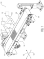
- FIG. 1 is a perspective view of vacuum conveyer system 100.
- Vacuum conveyer system 100 may generally comprise vacuum box 102, vacuum nose roll assembly 104, and moveable belt member 106.
- Moveable belt member 106 may be driven by belt motor assembly 103, which can drive belt member 106 to move about vacuum box 102 and vacuum nose roll assembly 104 in machine direction 120.
- Vacuum box 102 may generally include a hollow interior forming a discrete vacuum box vacuum chamber 130 (as depicted in FIG. 2 ), and the hollow interior may be connected to airflow conduit 110. Airflow conduit 110, in turn, may be connected to vacuum source 114. In this way, vacuum source 114 can create a pressure differential within vacuum box 102 relative to the space outside of vacuum box 102.
- vacuum box 102 may include a porous top surface, which, in combination with vacuum source 114, creates a suction force at the porous top surface of vacuum box 102 as air is pulled into vacuum box 102 due to the pressure differential between the inside of vacuum box 102 and the outside of vacuum box 102. In other embodiments, vacuum box 102 may be enclosed only on three sides while the top is left open. In such embodiments, belt member 106 may act as the top surface of vacuum box 102.
- Belt member 106 may generally be comprised of any number of suitable flexible materials, and in some embodiments may comprise a screen.
- belt member 106 may be comprised of any rubber material having suitable flexible properties enabling belt member 106 to bend around vacuum nose roll assembly 104.
- belt member 106 may be comprised of any suitable metal material that has the suitable flexibility. In general, these types of belt or screen members are well-known in the art.
- One important aspect of belt member 106 is that belt member 106 includes porous region 108.
- vacuum box 102 may be configured with vacuum source 114 to create a pressure differential within vacuum box 102 relative to the space outside of vacuum box 102.
- Porous region 108 of belt member 106 allows air to flow through belt member 106 and into vacuum box 102 due to the pressure differential, thereby creating a suction force at belt member 106. This suction force helps to maintain the positioning of materials and article components being transported on belt member 106.
- porous region 108 may take on any shape or size.
- porous region 108 could extend along belt member 106 all the way up to the entire length of belt member 106.
- porous region 108 extends approximately along the entire cross-machine direction 122 length of belt member 106.
- porous region 108 may only extend along a portion of the cross-machine direction 122 length of belt member 106, such as along a cross-machine direction 122 length approximately equal to a cross-machine direction 122 length of materials or article components to be transported on vacuum conveyer system 100.
- Vacuum nose roll assembly 104 may be generally disposed adjacent one end of vacuum conveyer system 100. In some embodiments, vacuum nose roll assembly 104 may be disposed adjacent an inlet end of system 100 where material is brought onto system 100. However, in other embodiments, vacuum nose roll assembly 104 may be disposed adjacent an outlet end of system 100 where material exits system 100. As will be described in more detail below, vacuum nose roll assembly 104 may comprise a discrete nose roll vacuum chamber 132 (as seen in FIG. 4 ) which is separate and distinct from vacuum box vacuum chamber 130 and not fluidly connected to vacuum box vacuum chamber 130. Vacuum conveyer system 100 may further comprise an airflow conduit that is separate from airflow conduit 110 and which connects vacuum nose roll assembly 104 to a vacuum source.
- system 100 may include airflow conduit 112a which connects vacuum nose roll assembly 104 to vacuum source 114, the same vacuum source that is connected to airflow conduit 110 and vacuum box 102.
- system 100 may include airflow conduit 112b which connects vacuum nose roll assembly 104 to vacuum source 116 which is separate from vacuum source 114.
- vacuum sources 114 and/or 116 may be vacuum pumps, fans, or any other suitable energy source configured to provide airflow out of vacuum box vacuum chamber 130 and nose vacuum chamber 132.
- Vacuum sources 114 and/or 116 may be configurable to provide adjustable pressure differentials within vacuum box vacuum chamber 130 and/or nose roll vacuum chamber 132.
- airflow conduits 110 and/or 112a, 112b may include one or more dampers which can be adjusted to provide different pressure differentials within vacuum box vacuum chamber 130 and/or nose roll vacuum chamber 132.
- the presence of distinct vacuum box vacuum chamber 130 and nose roll vacuum chamber 132 allows for greater control of the pressure differentials within each chamber 130, 132. This greater control may help to ensure that transported materials and article components maintain their position as they travel a path through a manufacturing process, both along a vacuum conveyer system such as system 100 and during transitions between adjacent conveyer systems.
- FIG. 2 is a perspective view of the vacuum conveyer system of FIG. 1 with belt member 106 removed.
- airflow conduit 112a (or 112b) connecting vacuum nose roll assembly 104 to one of vacuum sources 114, 116 may further connect to airflow conduit 113 which extends at least partially through vacuum box vacuum chamber 130.
- vacuum box vacuum chamber 130 is depicted as a single chamber, in other embodiments vacuum box vacuum chamber 130 may comprise two or more vacuum chambers with additional airflow conduits connecting each vacuum chamber to a vacuum source (or the same vacuum source in some embodiments).
- vacuum chamber 130 may comprise any suitable number of chambers, such as between 1 chamber and 5 chambers.
- vacuum conveyer system 100 may be suitable for transporting materials and article components used in the manufacture of absorbent articles.
- Example materials that vacuum conveyer system 100 may transport include webs constructed of any of a variety of materials, such as synthetic fibers (for example, polyester or polypropylene fibers), natural fibers (for example, wood or cotton fibers), a combination of natural and synthetic fibers, porous foams, reticulated foams, apertured plastic films, or the like.
- Such materials may be in the form of various woven and non-woven fabrics which can include spunbond fabric, meltblown fabric, coform fabric, carded web, bonded-carded web, bicomponent spunbond fabric, spunlace, or the like, as well as combinations thereof.
- Vacuum conveyer system 100 may also be suitable for transporting absorbent article components such as absorbent cores.
- Exemplary absorbent cores may be comprised generally of pulp fluff, SAM, or pulp fluff combined with SAM.
- Vacuum conveyer system 100 may be particularly useful in transporting materials and article components that are thin and flexible, for example absorbent cores that are equal to or greater than 75% of SAM by weight.
- vacuum conveyer system 100 may be suitable for transporting any suitable material, component, or product.
- vacuum source 114 may be configured to provide specific pressure differentials within vacuum box vacuum chamber 130 and nose roll vacuum chamber 132 (as seen in FIG. 4 ).
- vacuum source 114 may be fans rated at between about 1,000 cubic feet per minute (CFM) and about 10,000 CFM.
- Such vacuum source(s) may be able to create pressures of between about 0.5 inch of water (0.125 kPa) and about 100 inches water (25 kPa) within vacuum box vacuum chamber 130 and within nose roll vacuum chamber 132.
- vacuum source 114 (and/or 116) may be able to create pressure of between about 1 inch of water (0.25 kPa) and about 10 inches of water (25 kPa) within vacuum box vacuum chamber 130 and within nose roll vacuum chamber 132.
- FIG. 3 is a perspective view of nose roll assembly 104 of vacuum conveyer system 100.
- Nose roll assembly 104 generally comprises nose roll 150 and nose roll shaft 152.
- Nose roll 150 and nose roll shaft 152 are configured in a live-roll-dead-shaft configuration where nose roll shaft 152 maintains its rotational position throughout operation of vacuum conveyer system 100, and nose roll 150 rotates about nose roll shaft 152 during operation of vacuum conveyer system 100.
- Nose roll 150 generally comprises apertures 154, ridges 156, and smooth areas 158.
- Apertures 154 may allow air to flow through nose roll 150 and into nose roll vacuum chamber 132 (as seen in Figure 4 ), as evidenced by airflow paths 162.
- Ridges 156 may cooperate with sealing member 161 (as can be further seen in FIG. 4 ) to provide a seal between airflow conduit 113 and nose roll 150.
- smooth areas 158 may cooperate with sealing members 160 in order to provide a seal between airflow conduit 113 and nose roll 150.
- nose roll assembly 104 may further include adjustable inlet plate 164.
- adjustable inlet plate 164 may cover a portion of airflow conduit 113 and may further comprise apertures 166.
- adjustable inlet plate 164 may be a top portion of airflow conduit 113, and apertures 166 may allow air to enter airflow conduit 113, as depicted by air flow paths 162, thereby providing a suction force along adjustable inlet plate 164.
- vacuum conveyer systems 100 that include adjustable inlet plate 164 may provide a suction force on materials and article components as they pass over nose roll assembly 104 and transition past nose roll assembly 104 but before they pass over vacuum box vacuum chamber 130.
- adjustable inlet plate 164 may be moveable in the direction of arrows 165. Moving adjustable inlet plate 164 along a path aligned with arrows 165 may adjust both a positioning of the suction force due to the changing of location of apertures 166 (and/or opening a gap between nose roll 150 and adjustable inlet plate 164) and the level of suction force within airflow conduit 113 at adjustable inlet plate 164.
- plate 164 may be adjustable in a direction different than depicted by arrows 165, for example a direction having any angle with respect to arrows 165.
- plate 164 may comprise a pair of plates with aligned apertures. Moving the top plate of the pair in any direction may un-align the apertures of each of the pair of plates, thereby adjusting the suction strength along plate 164.
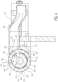
- FIG. 4 is a cross-section view of nose roll assembly 104 taken as viewed along line 4-4.
- vacuum nose roll 150 comprises apertures 154 and ridges 156. Apertures 154 of vacuum nose roll 150 may fluidly connect the exterior of vacuum nose roll 150 with the interior of vacuum nose roll 150 and with airflow conduit 113.
- vacuum source 114 and/or 116 may be connected to airflow conduit 112, which connects to air flow conduit 113. Accordingly, when vacuum source 114 (and/or 116) is in operation, air may move from the exterior of vacuum nose roll 150 to the interior of vacuum nose roll 150 through one or more apertures 154 and into nose roll vacuum chamber 132, as depicted by arrow 170.
- Nose roll vacuum chamber 132 may be formed by a recess of nose roll shaft 152.
- the air that entered nose roll vacuum chamber 132 may additionally move out of nose roll vacuum chamber 132 through one or more additional apertures 154 and into airflow conduit 113 due to the action of vacuum source 114 (and/or 116), as shown by arrow 171.
- vacuum source 114 (and/or 116), airflow conduits 113, 112, and nose roll assembly 104 may be configured to achieve a suction force at the outer surface of vacuum nose roll 150.
- apertures 154 may have chamfered inner edges 153 in order to help create smooth airflow into nose roll vacuum chamber 132.
- apertures 154 may comprise angled walls such that apertures 154 widen from as they extend toward nose roll vacuum chamber 132.
- Vacuum nose roll 150 may comprise both ridges 156 and recesses 157 and may further be described as having both a minor diameter and a major diameter due to ridges 156 and recesses 157. In this manner, vacuum nose roll 150 may comprise both surfaces 155, which may be the surface of the minor diameter of vacuum nose roll 150, and surfaces 159 which may be the surface of the major diameter of vacuum nose roll 150.
- Surfaces 159 may be the outer most portion of ridges 156, and ridges 156 may interact with sealing member 161 in order to form a seal between vacuum nose roll 150 and airflow conduit 112.
- ridges 156 and sealing member 161 may be configured such that there is a very small-to-no gap between surfaces 159 and sealing member 161 as ridges 156 pass adjacent to sealing member 161. This close fit forms a seal between vacuum nose roll 150 and airflow conduit 113 to help prevent air entering airflow conduit 113 from locations other than through vacuum nose roll 150 and nose roll vacuum chamber 132. Locations where air enters airflow conduit 113 from locations other than through vacuum nose roll 150 and nose roll vacuum chamber 132 may be thought of as "leaks".
- air entering airflow conduit 113 from locations other than through vacuum nose roll 150 and nose roll vacuum chamber 132 reduces the amount of pressure differential vacuum source 114 (and/or 116) may create between nose roll vacuum chamber 132 and the exterior of vacuum nose roll 150.
- This reduced pressure differential equates to a reduced suction force at the surface of vacuum nose roll 150.
- the specific configuration of sealing member 161 and of recesses 157 and surfaces 159 on vacuum nose roll 150 as shown in FIG. 4 is termed a labyrinth seal. In this configuration, as vacuum nose roll 150 spins about nose roll shaft 152, air becomes trapped within recesses 157 as they pass by sealing member 161. These trapped pockets of air further help to impede any airflow from outside of vacuum nose roll 150 into airflow conduit 113 from between vacuum nose roll 150 and sealing member 161 due to the relatively lower pressure within airflow conduit 113.
- sealing member 161 has a surface 163 which may curve to follow the contour of vacuum nose roll 150.
- surface 163 of sealing member 161 may have a contour length equal to between about 5% and about 25% of the circumference of vacuum nose roll 150.
- the contour length of surface 163 may be the length of surface 163 from the top of sealing member 167 to the bottom of sealing member 169, as seen in FIG. 4 , found by following the curvature of the surface 163.
- recesses 157 may have a maximum width of between about 0.5 mm and about 10 mm.
- recesses 157 may have a width that is equal to portion of a circumferential length of vacuum nose roll 150. In some embodiments, recesses 157 may have a maximum width equal to between about 0.5% and about 5% of the circumference of vacuum nose roll 150. Ridges 156 may have a radial height of between about 2 mm and about 20 mm.
- the maximum width of ridges 156 may be the same as the maximum width of the recesses 157. However, this is not necessary in all embodiments. For instance, the maximum width of ridges 156 may range between about 50% and about 200% of the maximum width of the recesses 157 in different embodiments.
- nose roll assembly 104 may further comprise recesses 168 disposed on nose roll shaft 152. Similar to recesses 157 and sealing member 161, recesses 168 and interior surface 151 of vacuum nose roll 150 may form a labyrinth seal to prevent air from entering nose roll vacuum chamber 132 and/or airflow conduit 113 from between vacuum nose roll 150 and nose roll shaft 152.
- recesses 168 may vary in depth between about 2 mm and about 20 mm. Additionally, recesses 168 may have a maximum width that ranges from about 0.5 mm to about 10 mm in different contemplated embodiments.
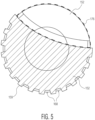
- Nose roll vacuum chamber 132 may be formed of a recess within nose roll shaft 152.
- a portion of nose roll shaft 152 not comprising the recess forming nose roll vacuum chamber 132 may have a first cross-sectional surface area, which comprises the area bounded by surfaces 159 of nose roll shaft 152 as shown in FIG. 5 .
- nose roll shaft 152 may have a second cross-sectional surface area at a portion of nose roll shaft 152 comprising the recess forming nose roll vacuum chamber 132. In the example of FIG. 5 , this second cross-sectional surface area would be the first cross-sectional surface area less the region bounded by dotted line 176 defining the recess forming nose roll vacuum chamber 132.
- the second cross-sectional surface area may be between 50% and 75% of the first cross-sectional surface area.
- the first cross-sectional surface area may be between about 10 in 2 (64.5 cm 2 ) and about 150 in 2 (968 cm 2 ). Accordingly, the second cross-sectional surface area may then be between about 5 in 2 (32.2 cm 2 ) and about 112.5 in 2 (726 cm 2 ). This would put the cross-sectional area of the region forming nose roll vacuum chamber 132, e.g. the region bounded by dotted line 176, between about 25% percent and about 50% of the first cross-sectional area.
- the cross-sectional area of the region forming nose roll vacuum chamber 132 may be between about 0.5 in 2 (3.2 cm 2 ) and about 52.5 in 2 (339 cm 2 ).
- nose roll 150 and nose roll shaft 152 may be as large or small as necessary for whatever particular desired application of vacuum conveyer system 100.
- nose roll shaft 152 may have a further feature where nose roll vacuum chamber 132 is substantially free of obstructions.
- Lower turbulence of air present in nose roll vacuum chamber 132 equates to lower levels of pressure able to be achieved by vacuum source 114 (and/or 116) given a static amount of vacuum energy supplied by vacuum source 114 (and/or 116). Accordingly, if nose roll vacuum chamber 132 is substantially free of obstructions, the greater the suction force may be achieved at nose roll surface 155 than where nose roll vacuum chamber 132 is not substantially free of obstructions.
- the phrase 'substantially free of obstructions' may be construed to mean there are no portions of nose roll shaft 152 or hardware or other members attached to nose roll shaft 152 which extend into nose roll vacuum chamber 132 an amount greater than about 10 mm.
Landscapes
- Engineering & Computer Science (AREA)
- Mechanical Engineering (AREA)
- General Engineering & Computer Science (AREA)
- Advancing Webs (AREA)
- Rollers For Roller Conveyors For Transfer (AREA)
Claims (8)
- Système de convoyeur sous vide (100) comprenant :un boîtier sous vide (102) s'étendant entre une première extrémité de boîtier et une deuxième extrémité de boîtier et comprenant une première chambre sous vide discrète (130) ;un rouleau avant (104) disposé de manière adjacente à la première extrémité de boîtier et comprenant une deuxième chambre sous vide discrète (132) ; etun organe à trous (106) disposé à la fois autour du rouleau avant et du boîtier sous vide ;caractérisé en ce que le rouleau avant comprend un arbre mort (152) et un rouleau actif (150), dans lequel un évidement (132) au sein de l'arbre mort forme la deuxième chambre sous vide discrète,et dans lequel le système comprend en outre : un conduit d'écoulement d'air (113) disposé de manière adjacente au rouleau actif ; etun joint labyrinthe (157, 159, 161) connectant le rouleau actif au conduit d'écoulement d'air (113).
- Système (100) selon la revendication 1, dans lequel une source de vide unique (114) fournit un vide à la fois à la première chambre sous vide discrète (130) et à la deuxième chambre sous vide discrète (132).
- Système (100) selon la revendication 1 ou 2, dans lequel une première source de vide (114) fournit un vide à la première chambre sous vide discrète (130) et dans lequel une deuxième source de vide (116) fournit un vide à la deuxième chambre sous vide discrète (132).
- Système (100) selon la revendication 1, 2 ou 3, dans lequel la deuxième chambre sous vide discrète (132) est externe à la première chambre sous vide discrète (130).
- Système (100) selon l'une quelconque des revendications 1 à 4, dans lequel la première extrémité de boîtier comprend une extrémité d'entrée du système de convoyeur sous vide.
- Système (100) selon l'une quelconque des revendications 1 à 5, dans lequel la deuxième chambre sous vide discrète (132) est exempte d'obstructions.
- Système (100) selon l'une quelconque des revendications 1 à 6, dans lequel une aire en coupe transversale d'une région (176) délimitée par l'évidement (132) comprend entre 25 % et 50 % d'une aire en coupe transversale d'une portion (159) de l'arbre mort (152) ne comprenant pas l'évidement.
- Système (100) selon l'une quelconque des revendications 1 à 7, dans lequel le rouleau actif comprend une pluralité d'ouvertures (154) pour permettre un écoulement d'air (170) jusque dans la deuxième chambre sous vide discrète (132), et dans lequel les ouvertures sont chanfreinées.
Applications Claiming Priority (1)
| Application Number | Priority Date | Filing Date | Title |
|---|---|---|---|
| PCT/US2016/067088 WO2018111292A1 (fr) | 2016-12-16 | 2016-12-16 | Rouleau de nez sous vide |
Publications (3)
| Publication Number | Publication Date |
|---|---|
| EP3554970A1 EP3554970A1 (fr) | 2019-10-23 |
| EP3554970A4 EP3554970A4 (fr) | 2020-08-19 |
| EP3554970B1 true EP3554970B1 (fr) | 2024-10-23 |
Family
ID=62559703
Family Applications (1)
| Application Number | Title | Priority Date | Filing Date |
|---|---|---|---|
| EP16924126.2A Active EP3554970B1 (fr) | 2016-12-16 | 2016-12-16 | Rouleau de nez sous vide |
Country Status (8)
| Country | Link |
|---|---|
| US (1) | US10781046B2 (fr) |
| EP (1) | EP3554970B1 (fr) |
| CN (1) | CN109952260B (fr) |
| AU (1) | AU2016432186B2 (fr) |
| BR (1) | BR112019010488B1 (fr) |
| MX (1) | MX2019005943A (fr) |
| RU (1) | RU2730807C1 (fr) |
| WO (1) | WO2018111292A1 (fr) |
Families Citing this family (4)
| Publication number | Priority date | Publication date | Assignee | Title |
|---|---|---|---|---|
| WO2017019176A1 (fr) | 2015-07-29 | 2017-02-02 | Kimberly-Clark Worldwide, Inc. | Composite absorbant comprenant des fibres absorbantes capables de gonfler |
| CN112108493B (zh) * | 2020-09-07 | 2023-12-05 | 青海黄河上游水电开发有限责任公司光伏产业技术分公司 | 一种光伏组件玻璃去除设备及去除方法 |
| CN111974788B (zh) * | 2020-09-07 | 2023-12-05 | 青海黄河上游水电开发有限责任公司光伏产业技术分公司 | 一种剥离机构及剥离方法 |
| EP4501826A1 (fr) * | 2023-08-02 | 2025-02-05 | Jesús Francisco Barberan Latorre | Table d'aspiration pour le transport de substrats |
Family Cites Families (52)
| Publication number | Priority date | Publication date | Assignee | Title |
|---|---|---|---|---|
| DE1132320B (de) | 1957-11-08 | 1962-06-28 | Alfons Thiel | Verfahren und Vorrichtung zum Vakuumverformen von Folien in Blatt- oder Bahnform aus thermoplastischem Kunststoff unter Anwendung eines Vorstreckvorganges |
| US3477558A (en) | 1966-10-27 | 1969-11-11 | Fred J Fleischauer | Air lift and vacuum conveyors and foraminous belt means therefor |
| US3757926A (en) * | 1971-06-29 | 1973-09-11 | Baker Perkins Inc | Transfer apparatus |
| US4025380A (en) | 1975-07-24 | 1977-05-24 | International Business Machines Corporation | Variable resist laminator |
| CA1060491A (fr) * | 1976-11-12 | 1979-08-14 | Steve Sarovich | Appareil a marche a vide de manutention et de mise d'aplomb des boites |
| DE3131687A1 (de) | 1981-08-11 | 1983-03-03 | Focke & Co, 2810 Verden | "verpackungs-vorrichtung zum herstellen von zuschnitten und zufuehren derselben in einer verpackungsstation" |
| US4602663A (en) | 1984-08-07 | 1986-07-29 | The Coe Manufacturing Co. | Veneer lathe with powered nose bar roll of large diameter |
| US4795335A (en) | 1987-07-20 | 1989-01-03 | Johnson & Johnson | Multi-headed ductless webber |
| US5271304A (en) | 1990-07-03 | 1993-12-21 | Carruthers Equipment Co. | Automatic food slicing machine |
| US5102490A (en) | 1990-11-05 | 1992-04-07 | The Goodyear Tire & Rubber Company | Apparatus for applying tire sheet components |
| CN1061371A (zh) * | 1990-11-13 | 1992-05-27 | 四川东华机械厂 | 真空伏辊长网成型机 |
| CN1112893A (zh) * | 1994-05-12 | 1995-12-06 | 吉第联合股份公司 | 制造易撕带的方法和装置 |
| DE4442629C2 (de) * | 1994-12-01 | 1998-05-07 | Heidelberger Druckmasch Ag | Saugbändertisch |
| JPH08175718A (ja) * | 1994-12-21 | 1996-07-09 | Bridgestone Corp | 帯状部材の送出し装置 |
| US5544557A (en) | 1995-01-13 | 1996-08-13 | Paper Converting Machine Company | Method and apparatus for cutting superposed webs |
| CA2205795A1 (fr) | 1996-05-31 | 1997-11-30 | Scott C. Romenesko | Machine pour former des rouleaux de bandes continues ou interfoliees |
| US5890301A (en) | 1997-11-11 | 1999-04-06 | Marquip, Inc. | Thread-up apparatus for a corrugator double backer |
| US6216848B1 (en) * | 1999-04-09 | 2001-04-17 | Profold, Inc. | Vacuum table conveying apparatus and associated methods |
| US6254090B1 (en) * | 1999-04-14 | 2001-07-03 | Hewlett-Packard Company | Vacuum control for vacuum holddown |
| US6227541B1 (en) * | 1999-07-01 | 2001-05-08 | Kimberly-Clark Worldwide, Inc. | Multiple conveyor assembly and method for rotating and placing a strip of material on a substrate |
| US6270629B1 (en) | 1999-08-13 | 2001-08-07 | Voith Sulzer Papertechnik Patent Gmbh | Web handling apparatus |
| US6648122B1 (en) * | 2000-10-25 | 2003-11-18 | Curt G. Joa, Inc. | Apparatus for transferring articles |
| US6733431B2 (en) | 2001-09-19 | 2004-05-11 | Heidelberger Druckmaschinen Ag | Device and method for folding newspapers with flexible inserting position |
| US6888143B2 (en) | 2002-03-09 | 2005-05-03 | Kimberly-Clark Worldwide, Inc. | Apparatus and method for inspecting pre-fastened articles |
| US6854624B2 (en) | 2002-06-06 | 2005-02-15 | Kimberly-Clark Worldwide, Inc. | Methods for improving product chassis and panel control during folding of garment |
| JP2004224565A (ja) * | 2003-01-27 | 2004-08-12 | Yasukuni Kishimoto | 粘着性弱の総菜等の反転と移載装置 |
| JP4571812B2 (ja) * | 2003-02-24 | 2010-10-27 | ハイデルベルガー ドルツクマシーネン アクチエンゲゼルシヤフト | シート搬送装置 |
| FI118017B (fi) * | 2004-03-11 | 2007-05-31 | Metso Paper Inc | Alipainehihnakuljetin päänvientinauhan viemiseksi rainanmuodostuskoneessa |
| ATE430659T1 (de) * | 2004-10-04 | 2009-05-15 | Oce Tech Bv | Vorrichtung zum handhaben von bögen |
| DE102005007473B4 (de) * | 2005-02-18 | 2007-04-19 | Christian Beer | Vakuumförderer mit drehender Luftzuführung |
| US7398870B2 (en) * | 2005-10-05 | 2008-07-15 | Curt G. Joa, Inc | Article transfer and placement apparatus |
| US7780052B2 (en) * | 2006-05-18 | 2010-08-24 | Curt G. Joa, Inc. | Trim removal system |
| US20080149258A1 (en) | 2006-12-21 | 2008-06-26 | Daniel Ray Downing | Tire assembly applier with cutter mechanism |
| US9944487B2 (en) * | 2007-02-21 | 2018-04-17 | Curt G. Joa, Inc. | Single transfer insert placement method and apparatus |
| US9387131B2 (en) * | 2007-07-20 | 2016-07-12 | Curt G. Joa, Inc. | Apparatus and method for minimizing waste and improving quality and production in web processing operations by automated threading and re-threading of web materials |
| CN201309607Y (zh) * | 2008-06-20 | 2009-09-16 | 吴为荣 | 卷烟包装机条透吸风带输送装置 |
| DE102009025588B4 (de) * | 2008-07-11 | 2022-02-24 | Heidelberger Druckmaschinen Ag | Vorrichtung zum Zuführen und Ausrichten von Bogen, die einer Verarbeitungsmaschine, insbesondere Druckmaschine zugeführt werden |
| JP5513167B2 (ja) | 2009-03-02 | 2014-06-04 | ユニ・チャーム株式会社 | コンベア装置及び吸収性物品の製造方法 |
| US8100253B2 (en) * | 2009-06-30 | 2012-01-24 | The Procter & Gamble Company | Methods and apparatuses for transferring discrete articles between carriers |
| CN201485014U (zh) * | 2009-07-23 | 2010-05-26 | 贝高(杭州)机械有限公司 | 真空吸附输送系统 |
| US8863939B2 (en) * | 2009-12-14 | 2014-10-21 | Xerox Corporation | Surface roughness for improved vacuum pressure for efficient media hold-down performance |
| WO2011138440A2 (fr) * | 2010-05-07 | 2011-11-10 | Böwe Systec Gmbh | Appareil et procédé pour l'insertion d'une ou de plusieurs marchandises dans une boîte mobile |
| FR2967664B1 (fr) * | 2010-11-24 | 2012-12-28 | Goss Int Montataire Sa | Dispositif de transport d'une feuille, et utilisation correspondante |
| RU2622828C2 (ru) * | 2012-10-23 | 2017-06-20 | Дзе Проктер Энд Гэмбл Компани | Способы перемещения дискретных компонентов на полотно |
| CN104176540A (zh) * | 2013-05-24 | 2014-12-03 | 佛山市宝索机械制造有限公司 | 具有双功能吸气式起卷机构的复卷机 |
| CN203582089U (zh) * | 2013-11-08 | 2014-05-07 | 圣戈班研发(上海)有限公司 | 一种真空辊 |
| CN203638848U (zh) * | 2013-11-11 | 2014-06-11 | 株式会社瑞光 | 吸收性物品的搬送装置 |
| KR101529875B1 (ko) * | 2013-12-03 | 2015-06-18 | 이규모 | 흡착식 포장제품 이송장치 |
| US9573766B2 (en) * | 2013-12-05 | 2017-02-21 | The Procter & Gamble Company | Apparatus and method for conveying absorbent articles |
| US9850404B2 (en) * | 2014-07-31 | 2017-12-26 | Nike, Inc. | Vacuum enabled article transfer |
| US10167156B2 (en) * | 2015-07-24 | 2019-01-01 | Curt G. Joa, Inc. | Vacuum commutation apparatus and methods |
| CN105413290A (zh) * | 2015-12-09 | 2016-03-23 | 昆山菲萝环保设备有限公司 | 滤带辊洗式全自动带式真空过滤机 |
-
2016
- 2016-12-16 EP EP16924126.2A patent/EP3554970B1/fr active Active
- 2016-12-16 WO PCT/US2016/067088 patent/WO2018111292A1/fr not_active Ceased
- 2016-12-16 US US16/468,147 patent/US10781046B2/en active Active
- 2016-12-16 RU RU2019117589A patent/RU2730807C1/ru active
- 2016-12-16 AU AU2016432186A patent/AU2016432186B2/en active Active
- 2016-12-16 CN CN201680090841.3A patent/CN109952260B/zh active Active
- 2016-12-16 BR BR112019010488-7A patent/BR112019010488B1/pt active IP Right Grant
- 2016-12-16 MX MX2019005943A patent/MX2019005943A/es unknown
Also Published As
| Publication number | Publication date |
|---|---|
| CN109952260A (zh) | 2019-06-28 |
| EP3554970A1 (fr) | 2019-10-23 |
| AU2016432186B2 (en) | 2023-05-18 |
| US20190308815A1 (en) | 2019-10-10 |
| BR112019010488A2 (pt) | 2019-09-10 |
| EP3554970A4 (fr) | 2020-08-19 |
| MX2019005943A (es) | 2019-08-26 |
| BR112019010488B1 (pt) | 2022-04-26 |
| AU2016432186A1 (en) | 2019-06-20 |
| US10781046B2 (en) | 2020-09-22 |
| WO2018111292A1 (fr) | 2018-06-21 |
| CN109952260B (zh) | 2022-08-02 |
| RU2730807C1 (ru) | 2020-08-26 |
Similar Documents
| Publication | Publication Date | Title |
|---|---|---|
| EP3554970B1 (fr) | Rouleau de nez sous vide | |
| ES2305231T3 (es) | Tambor de conformacion multi-etapas, con conmutador de vacio. | |
| JP4542900B2 (ja) | 複数の重ね合わされた繊維層を持つ物品を空気形成する方法及び装置 | |
| JP6239695B2 (ja) | 別個の物品を移送する方法 | |
| JP3983172B2 (ja) | 改善された坪量をもつ堆積繊維性ウェブを形成する装置及びプロセス | |
| JP5261604B2 (ja) | 積繊装置 | |
| JP4613064B2 (ja) | 空気形成繊維性ウエブの形成のための装置及び型 | |
| ES2282603T3 (es) | Procedimiento y aparato para la fabricacion de un elemento absorbente fibroso reforzado. | |
| JP6429603B2 (ja) | 吸収体の製造方法 | |
| JP2015513992A (ja) | 回転アセンブリ及び別個の物品を移送する方法 | |
| JP6605631B2 (ja) | 別個の物品を移送するための方法 | |
| JP2017094108A (ja) | 流体システム及び別個の物品を移送する方法 | |
| CA2622049A1 (fr) | Methode et appareil pour le positionnement d'un insert en une seule operation | |
| BRPI0617609A2 (pt) | dispositivo para mudanÇa de passo de separaÇço entre os artigos transportados | |
| TWI753927B (zh) | 吸收體之製造裝置及吸收體之製造方法 | |
| JP5238394B2 (ja) | 吸収体の製造装置及び製造方法 | |
| JP5892883B2 (ja) | 吸収体製造装置 | |
| JP5457507B2 (ja) | 積繊装置 | |
| JP5261557B2 (ja) | 積繊装置 | |
| KR101073850B1 (ko) | 내통고정 외통회전식 원단 피딩롤 | |
| JP5624877B2 (ja) | 吸収体の製造方法及び製造装置 | |
| KR101888614B1 (ko) | 식품 포장용 필름 이물질 흡입장치 | |
| JP6226470B2 (ja) | 吸収性物品の搬送装置および搬送方法 | |
| JP6864466B2 (ja) | 吸収体の製造装置 | |
| US20220257428A1 (en) | Apparatuses and methods for manufacturing absorbent structures including flexible masking media |
Legal Events
| Date | Code | Title | Description |
|---|---|---|---|
| STAA | Information on the status of an ep patent application or granted ep patent |
Free format text: STATUS: THE INTERNATIONAL PUBLICATION HAS BEEN MADE |
|
| PUAI | Public reference made under article 153(3) epc to a published international application that has entered the european phase |
Free format text: ORIGINAL CODE: 0009012 |
|
| STAA | Information on the status of an ep patent application or granted ep patent |
Free format text: STATUS: REQUEST FOR EXAMINATION WAS MADE |
|
| 17P | Request for examination filed |
Effective date: 20190701 |
|
| AK | Designated contracting states |
Kind code of ref document: A1 Designated state(s): AL AT BE BG CH CY CZ DE DK EE ES FI FR GB GR HR HU IE IS IT LI LT LU LV MC MK MT NL NO PL PT RO RS SE SI SK SM TR |
|
| AX | Request for extension of the european patent |
Extension state: BA ME |
|
| DAV | Request for validation of the european patent (deleted) | ||
| DAX | Request for extension of the european patent (deleted) | ||
| A4 | Supplementary search report drawn up and despatched |
Effective date: 20200721 |
|
| RIC1 | Information provided on ipc code assigned before grant |
Ipc: B65G 15/58 20060101ALN20200715BHEP Ipc: F16C 13/00 20060101ALI20200715BHEP Ipc: B65G 21/20 20060101ALI20200715BHEP Ipc: B65G 39/02 20060101AFI20200715BHEP |
|
| GRAP | Despatch of communication of intention to grant a patent |
Free format text: ORIGINAL CODE: EPIDOSNIGR1 |
|
| STAA | Information on the status of an ep patent application or granted ep patent |
Free format text: STATUS: GRANT OF PATENT IS INTENDED |
|
| RIC1 | Information provided on ipc code assigned before grant |
Ipc: B65G 15/58 20060101ALN20231108BHEP Ipc: B65G 21/20 20060101ALI20231108BHEP Ipc: F16C 13/00 20060101ALI20231108BHEP Ipc: B65G 39/02 20060101AFI20231108BHEP |
|
| RIC1 | Information provided on ipc code assigned before grant |
Ipc: B65G 15/58 20060101ALN20231114BHEP Ipc: B65G 21/20 20060101ALI20231114BHEP Ipc: F16C 13/00 20060101ALI20231114BHEP Ipc: B65G 39/02 20060101AFI20231114BHEP |
|
| INTG | Intention to grant announced |
Effective date: 20231204 |
|
| RIN1 | Information on inventor provided before grant (corrected) |
Inventor name: MATTIOLI, MICHAEL Inventor name: VENTURINO, MICHAEL B. Inventor name: KONETZKE, RICHARD M. |
|
| GRAJ | Information related to disapproval of communication of intention to grant by the applicant or resumption of examination proceedings by the epo deleted |
Free format text: ORIGINAL CODE: EPIDOSDIGR1 |
|
| STAA | Information on the status of an ep patent application or granted ep patent |
Free format text: STATUS: REQUEST FOR EXAMINATION WAS MADE |
|
| INTC | Intention to grant announced (deleted) | ||
| GRAP | Despatch of communication of intention to grant a patent |
Free format text: ORIGINAL CODE: EPIDOSNIGR1 |
|
| STAA | Information on the status of an ep patent application or granted ep patent |
Free format text: STATUS: GRANT OF PATENT IS INTENDED |
|
| RIC1 | Information provided on ipc code assigned before grant |
Ipc: B65G 15/58 20060101ALN20240418BHEP Ipc: B65G 21/20 20060101ALI20240418BHEP Ipc: F16C 13/00 20060101ALI20240418BHEP Ipc: B65G 39/02 20060101AFI20240418BHEP |
|
| INTG | Intention to grant announced |
Effective date: 20240514 |
|
| GRAS | Grant fee paid |
Free format text: ORIGINAL CODE: EPIDOSNIGR3 |
|
| GRAA | (expected) grant |
Free format text: ORIGINAL CODE: 0009210 |
|
| STAA | Information on the status of an ep patent application or granted ep patent |
Free format text: STATUS: THE PATENT HAS BEEN GRANTED |
|
| AK | Designated contracting states |
Kind code of ref document: B1 Designated state(s): AL AT BE BG CH CY CZ DE DK EE ES FI FR GB GR HR HU IE IS IT LI LT LU LV MC MK MT NL NO PL PT RO RS SE SI SK SM TR |
|
| REG | Reference to a national code |
Ref country code: GB Ref legal event code: FG4D |
|
| REG | Reference to a national code |
Ref country code: CH Ref legal event code: EP |
|
| REG | Reference to a national code |
Ref country code: DE Ref legal event code: R096 Ref document number: 602016089988 Country of ref document: DE |
|
| REG | Reference to a national code |
Ref country code: IE Ref legal event code: FG4D |
|
| P01 | Opt-out of the competence of the unified patent court (upc) registered |
Free format text: CASE NUMBER: APP_56802/2024 Effective date: 20241017 |
|
| RAP4 | Party data changed (patent owner data changed or rights of a patent transferred) |
Owner name: KIMBERLY-CLARK WORLDWIDE, INC. |
|
| PGFP | Annual fee paid to national office [announced via postgrant information from national office to epo] |
Ref country code: IT Payment date: 20241218 Year of fee payment: 9 |
|
| REG | Reference to a national code |
Ref country code: LT Ref legal event code: MG9D |
|
| REG | Reference to a national code |
Ref country code: NL Ref legal event code: MP Effective date: 20241023 |
|
| REG | Reference to a national code |
Ref country code: AT Ref legal event code: MK05 Ref document number: 1734687 Country of ref document: AT Kind code of ref document: T Effective date: 20241023 |
|
| PG25 | Lapsed in a contracting state [announced via postgrant information from national office to epo] |
Ref country code: NL Free format text: LAPSE BECAUSE OF FAILURE TO SUBMIT A TRANSLATION OF THE DESCRIPTION OR TO PAY THE FEE WITHIN THE PRESCRIBED TIME-LIMIT Effective date: 20241023 |
|
| PG25 | Lapsed in a contracting state [announced via postgrant information from national office to epo] |
Ref country code: NL Free format text: LAPSE BECAUSE OF FAILURE TO SUBMIT A TRANSLATION OF THE DESCRIPTION OR TO PAY THE FEE WITHIN THE PRESCRIBED TIME-LIMIT Effective date: 20241023 |
|
| PG25 | Lapsed in a contracting state [announced via postgrant information from national office to epo] |
Ref country code: IS Free format text: LAPSE BECAUSE OF FAILURE TO SUBMIT A TRANSLATION OF THE DESCRIPTION OR TO PAY THE FEE WITHIN THE PRESCRIBED TIME-LIMIT Effective date: 20250223 Ref country code: HR Free format text: LAPSE BECAUSE OF FAILURE TO SUBMIT A TRANSLATION OF THE DESCRIPTION OR TO PAY THE FEE WITHIN THE PRESCRIBED TIME-LIMIT Effective date: 20241023 Ref country code: PT Free format text: LAPSE BECAUSE OF FAILURE TO SUBMIT A TRANSLATION OF THE DESCRIPTION OR TO PAY THE FEE WITHIN THE PRESCRIBED TIME-LIMIT Effective date: 20250224 |
|
| PG25 | Lapsed in a contracting state [announced via postgrant information from national office to epo] |
Ref country code: FI Free format text: LAPSE BECAUSE OF FAILURE TO SUBMIT A TRANSLATION OF THE DESCRIPTION OR TO PAY THE FEE WITHIN THE PRESCRIBED TIME-LIMIT Effective date: 20241023 |
|
| PG25 | Lapsed in a contracting state [announced via postgrant information from national office to epo] |
Ref country code: BG Free format text: LAPSE BECAUSE OF FAILURE TO SUBMIT A TRANSLATION OF THE DESCRIPTION OR TO PAY THE FEE WITHIN THE PRESCRIBED TIME-LIMIT Effective date: 20241023 |
|
| PG25 | Lapsed in a contracting state [announced via postgrant information from national office to epo] |
Ref country code: ES Free format text: LAPSE BECAUSE OF FAILURE TO SUBMIT A TRANSLATION OF THE DESCRIPTION OR TO PAY THE FEE WITHIN THE PRESCRIBED TIME-LIMIT Effective date: 20241023 |
|
| PG25 | Lapsed in a contracting state [announced via postgrant information from national office to epo] |
Ref country code: NO Free format text: LAPSE BECAUSE OF FAILURE TO SUBMIT A TRANSLATION OF THE DESCRIPTION OR TO PAY THE FEE WITHIN THE PRESCRIBED TIME-LIMIT Effective date: 20250123 |
|
| PG25 | Lapsed in a contracting state [announced via postgrant information from national office to epo] |
Ref country code: LV Free format text: LAPSE BECAUSE OF FAILURE TO SUBMIT A TRANSLATION OF THE DESCRIPTION OR TO PAY THE FEE WITHIN THE PRESCRIBED TIME-LIMIT Effective date: 20241023 Ref country code: GR Free format text: LAPSE BECAUSE OF FAILURE TO SUBMIT A TRANSLATION OF THE DESCRIPTION OR TO PAY THE FEE WITHIN THE PRESCRIBED TIME-LIMIT Effective date: 20250124 Ref country code: AT Free format text: LAPSE BECAUSE OF FAILURE TO SUBMIT A TRANSLATION OF THE DESCRIPTION OR TO PAY THE FEE WITHIN THE PRESCRIBED TIME-LIMIT Effective date: 20241023 |
|
| PG25 | Lapsed in a contracting state [announced via postgrant information from national office to epo] |
Ref country code: PL Free format text: LAPSE BECAUSE OF FAILURE TO SUBMIT A TRANSLATION OF THE DESCRIPTION OR TO PAY THE FEE WITHIN THE PRESCRIBED TIME-LIMIT Effective date: 20241023 |
|
| PG25 | Lapsed in a contracting state [announced via postgrant information from national office to epo] |
Ref country code: RS Free format text: LAPSE BECAUSE OF FAILURE TO SUBMIT A TRANSLATION OF THE DESCRIPTION OR TO PAY THE FEE WITHIN THE PRESCRIBED TIME-LIMIT Effective date: 20250123 |
|
| REG | Reference to a national code |
Ref country code: DE Ref legal event code: R119 Ref document number: 602016089988 Country of ref document: DE |
|
| PG25 | Lapsed in a contracting state [announced via postgrant information from national office to epo] |
Ref country code: SM Free format text: LAPSE BECAUSE OF FAILURE TO SUBMIT A TRANSLATION OF THE DESCRIPTION OR TO PAY THE FEE WITHIN THE PRESCRIBED TIME-LIMIT Effective date: 20241023 |
|
| PG25 | Lapsed in a contracting state [announced via postgrant information from national office to epo] |
Ref country code: MC Free format text: LAPSE BECAUSE OF FAILURE TO SUBMIT A TRANSLATION OF THE DESCRIPTION OR TO PAY THE FEE WITHIN THE PRESCRIBED TIME-LIMIT Effective date: 20241023 |
|
| PG25 | Lapsed in a contracting state [announced via postgrant information from national office to epo] |
Ref country code: DK Free format text: LAPSE BECAUSE OF FAILURE TO SUBMIT A TRANSLATION OF THE DESCRIPTION OR TO PAY THE FEE WITHIN THE PRESCRIBED TIME-LIMIT Effective date: 20241023 |
|
| PG25 | Lapsed in a contracting state [announced via postgrant information from national office to epo] |
Ref country code: EE Free format text: LAPSE BECAUSE OF FAILURE TO SUBMIT A TRANSLATION OF THE DESCRIPTION OR TO PAY THE FEE WITHIN THE PRESCRIBED TIME-LIMIT Effective date: 20241023 |
|
| PG25 | Lapsed in a contracting state [announced via postgrant information from national office to epo] |
Ref country code: RO Free format text: LAPSE BECAUSE OF FAILURE TO SUBMIT A TRANSLATION OF THE DESCRIPTION OR TO PAY THE FEE WITHIN THE PRESCRIBED TIME-LIMIT Effective date: 20241023 |
|
| PG25 | Lapsed in a contracting state [announced via postgrant information from national office to epo] |
Ref country code: SK Free format text: LAPSE BECAUSE OF FAILURE TO SUBMIT A TRANSLATION OF THE DESCRIPTION OR TO PAY THE FEE WITHIN THE PRESCRIBED TIME-LIMIT Effective date: 20241023 |
|
| PG25 | Lapsed in a contracting state [announced via postgrant information from national office to epo] |
Ref country code: CZ Free format text: LAPSE BECAUSE OF FAILURE TO SUBMIT A TRANSLATION OF THE DESCRIPTION OR TO PAY THE FEE WITHIN THE PRESCRIBED TIME-LIMIT Effective date: 20241023 |
|
| REG | Reference to a national code |
Ref country code: CH Ref legal event code: PL |
|
| PG25 | Lapsed in a contracting state [announced via postgrant information from national office to epo] |
Ref country code: LU Free format text: LAPSE BECAUSE OF NON-PAYMENT OF DUE FEES Effective date: 20241216 |
|
| PLBE | No opposition filed within time limit |
Free format text: ORIGINAL CODE: 0009261 |
|
| STAA | Information on the status of an ep patent application or granted ep patent |
Free format text: STATUS: NO OPPOSITION FILED WITHIN TIME LIMIT |
|
| PG25 | Lapsed in a contracting state [announced via postgrant information from national office to epo] |
Ref country code: SE Free format text: LAPSE BECAUSE OF FAILURE TO SUBMIT A TRANSLATION OF THE DESCRIPTION OR TO PAY THE FEE WITHIN THE PRESCRIBED TIME-LIMIT Effective date: 20241023 |
|
| GBPC | Gb: european patent ceased through non-payment of renewal fee |
Effective date: 20250123 |
|
| 26N | No opposition filed |
Effective date: 20250724 |
|
| REG | Reference to a national code |
Ref country code: BE Ref legal event code: MM Effective date: 20241231 |
|
| PG25 | Lapsed in a contracting state [announced via postgrant information from national office to epo] |
Ref country code: DE Free format text: LAPSE BECAUSE OF NON-PAYMENT OF DUE FEES Effective date: 20250701 |
|
| PG25 | Lapsed in a contracting state [announced via postgrant information from national office to epo] |
Ref country code: GB Free format text: LAPSE BECAUSE OF NON-PAYMENT OF DUE FEES Effective date: 20250123 Ref country code: BE Free format text: LAPSE BECAUSE OF NON-PAYMENT OF DUE FEES Effective date: 20241231 |
|
| PG25 | Lapsed in a contracting state [announced via postgrant information from national office to epo] |
Ref country code: FR Free format text: LAPSE BECAUSE OF NON-PAYMENT OF DUE FEES Effective date: 20241223 |
|
| PG25 | Lapsed in a contracting state [announced via postgrant information from national office to epo] |
Ref country code: CH Free format text: LAPSE BECAUSE OF NON-PAYMENT OF DUE FEES Effective date: 20241231 |
|
| PG25 | Lapsed in a contracting state [announced via postgrant information from national office to epo] |
Ref country code: IE Free format text: LAPSE BECAUSE OF NON-PAYMENT OF DUE FEES Effective date: 20241216 |