EP3554765B1 - Procédé de commande pour une machine-outil manuelle de frappe - Google Patents
Procédé de commande pour une machine-outil manuelle de frappe Download PDFInfo
- Publication number
- EP3554765B1 EP3554765B1 EP17808505.6A EP17808505A EP3554765B1 EP 3554765 B1 EP3554765 B1 EP 3554765B1 EP 17808505 A EP17808505 A EP 17808505A EP 3554765 B1 EP3554765 B1 EP 3554765B1
- Authority
- EP
- European Patent Office
- Prior art keywords
- repetition rate
- temperature
- control method
- acceleration
- exciter
- Prior art date
- Legal status (The legal status is an assumption and is not a legal conclusion. Google has not performed a legal analysis and makes no representation as to the accuracy of the status listed.)
- Active
Links
Images


Classifications
-
- B—PERFORMING OPERATIONS; TRANSPORTING
- B25—HAND TOOLS; PORTABLE POWER-DRIVEN TOOLS; MANIPULATORS
- B25D—PERCUSSIVE TOOLS
- B25D11/00—Portable percussive tools with electromotor or other motor drive
-
- B—PERFORMING OPERATIONS; TRANSPORTING
- B25—HAND TOOLS; PORTABLE POWER-DRIVEN TOOLS; MANIPULATORS
- B25D—PERCUSSIVE TOOLS
- B25D11/00—Portable percussive tools with electromotor or other motor drive
- B25D11/06—Means for driving the impulse member
-
- B—PERFORMING OPERATIONS; TRANSPORTING
- B25—HAND TOOLS; PORTABLE POWER-DRIVEN TOOLS; MANIPULATORS
- B25D—PERCUSSIVE TOOLS
- B25D2216/00—Details of portable percussive machines with superimposed rotation, the rotational movement of the output shaft of a motor being modified to generate axial impacts on the tool bit
- B25D2216/0007—Details of percussion or rotation modes
- B25D2216/0015—Tools having a percussion-only mode
-
- B—PERFORMING OPERATIONS; TRANSPORTING
- B25—HAND TOOLS; PORTABLE POWER-DRIVEN TOOLS; MANIPULATORS
- B25D—PERCUSSIVE TOOLS
- B25D2250/00—General details of portable percussive tools; Components used in portable percussive tools
- B25D2250/195—Regulation means
- B25D2250/201—Regulation means for speed, e.g. drilling or percussion speed
-
- B—PERFORMING OPERATIONS; TRANSPORTING
- B25—HAND TOOLS; PORTABLE POWER-DRIVEN TOOLS; MANIPULATORS
- B25D—PERCUSSIVE TOOLS
- B25D2250/00—General details of portable percussive tools; Components used in portable percussive tools
- B25D2250/221—Sensors
Definitions
- the present invention relates to control methods for a percussive power tool, in particular a hand-held pneumatic hammer drill and a hand-held pneumatic electric chisel.
- the hammer mechanism of a rotary hammer heats up during operation due to the friction of moving components and thermal losses in the air spring.
- the operating temperature is between 80 °C and 150 °C.
- Lubrication, seals, dimensions and tolerances of the impact mechanism are designed with regard to the typical operating temperature.
- the impact mechanism is cold, especially in cold working environments below freezing. The conditions are not optimal for the impact mechanism and can prevent the impact mechanism from starting reliably.
- a control method for a percussive handheld power tool according to claim 1 has the steps: detecting a switching state of an operating button, detecting a temperature with a temperature sensor, activating an electro-pneumatic impact mechanism in response to the operating button being actuated, with an exciter of the electro-pneumatic impact mechanism moving along a The working axis is moved back and forth at a repetition rate R, which moves a beater coupled to the exciter via a pneumatic chamber. If the temperature is greater than a limit temperature, the repetition rate is continuously increased from rest to a setpoint. A number of exciter cycles until the target value is reached is less than 10 cycles. If the temperature is less than the limit temperature, a number of cycles of the exciter to reach the setpoint is greater than 200 cycles.
- the repetition rate is continuously increased with a first acceleration. Otherwise, if the temperature is lower than the limit temperature, in a first phase a Driven intermediate value, the repetition rate is increased at least in sections with the first acceleration, and in a second phase, the repetition rate with a second acceleration up to the setpoint continuously increased.
- the second acceleration can be less than 1/10 of the first acceleration.
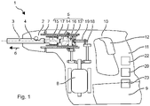
- the rotary hammer 1 shows a hammer drill 1 as an example of a percussive hand-held machine tool.
- the rotary hammer 1 has a tool holder 2, in which a drill, chisel or other striking tool 4 can be used and locked coaxially to a working axis 3 .
- the hammer drill 1 has a pneumatic impact mechanism 5 which can periodically strike the tool 4 in an impact direction 6 .
- a rotary drive 7 can continuously rotate the tool holder 2 about the working axis 3 .
- the pneumatic percussion mechanism 5 and the rotary drive are driven by an electric motor 8 , which is fed with electricity from a battery 9 or a mains line.
- the hammer mechanism 5 and the rotary drive 7 are arranged in a machine housing 10 .
- a handle 11 is typically arranged on a side of the machine housing 10 facing away from the tool holder 2 .
- the user can use the handle 11 to hold and guide the rotary hammer 1 during operation.
- An additional auxiliary handle can be attached near the tool holder 2 .
- On or near the handle 11 is a Operating button 12 arranged, which the user can preferably operate with the holding hand.
- the electric motor 8 is switched on by pressing the operating button 12 . Typically, the electric motor 8 rotates as long as the operating button 12 is held down.
- the pneumatic hammer mechanism 5 has an exciter 13, a hammer 14 and optionally a die 15 along the direction of impact 6.
- the exciter 13 is forced to move periodically along the working axis 3 by means of the electric motor 8 .
- the beater 14 couples to the movement of the exciter 13 via an air spring.
- the air spring is formed by a closed pneumatic chamber 16 between the exciter 13 and the beater 14 .
- the bat 14 moves in the direction of impact 6 until the bat 14 hits the die 15 .
- the die 15 rests against the tool 4 in the impact direction 6 and transfers the impact to the tool 4.
- the exemplary percussion mechanism 5 has a piston-shaped exciter 13 and a piston-shaped hammer 14 which are guided along the working axis 3 through a guide tube 17 .
- the exciter 13 and the beater 14 bear against the inner surface of the guide tube 17 with their lateral surfaces.
- the pneumatic chamber 16 is closed off by the exciter 13 and the beater 14 along the working axis 3 and by the guide tube 17 in the radial direction. Sealing rings in the lateral surfaces of the exciter 13 and the beater 14 can improve the airtight closure of the pneumatic chamber 16 .
- the exciter 13 is connected to the electric motor 8 via a transmission component.
- the gear component transfers the rotational movement of the electric motor 8 into a periodic translational movement along the working axis 3.
- An exemplary gear component is based on an eccentric wheel 18 which is connected to the electric motor 8 .
- a connecting rod 19 connects the eccentric wheel 18 to the exciter 13.
- the exciter 13 moves synchronously with the electric motor 8.
- the electric motor 8 typically rotates in response to the operation button 12 being pressed and continues to rotate as long as the user keeps the operation button 12 pressed.
- the periodic forward and backward movement of the exciter 13 also begins and ends when the operating button 12 is actuated or released.
- Another example of such a transmission component is a wobble drive.
- the exciter 13 moves at a repetition rate R which is proportional to the speed of the electric motor 8 .
- the transmission components between the electric motor 8 and the exciter 13 typically have a step-down effect in a fixed ratio.
- the repetition rate R is in the range, for example, between 30 cycles per second (Hz) and 150 Hz.
- the beater 14 is coupled to the exciter 13 by the pneumatic chamber 16 and moves at the same repetition rate as the exciter 13.
- the beater 14 is coupled to the exciter 13 exclusively via an air spring.
- the air spring is based on a pressure difference between the pressure in the pneumatic chamber 16 and the pressure in the environment.
- the positively moved exciter 13 increases or decreases the pressure in the pneumatic chamber 16 by means of its periodic axial movement.
- the hammer 14 is accelerated by the pressure difference in the direction of impact 6 or counter to the direction of impact 6 .
- the hammer drill 1 has a device control 20 which specifies the repetition rate R of the exciter 13 .
- the device controller 20 controls the electric motor 8 .
- the electric motor 8 contains a speed controller, for which a target value for the speed is specified by the device controller 20 .
- Speed control can also be implemented in the implement controller 20 based on a speed sensor on the motor shaft and a negative feedback loop.
- the device controller 20 can limit a power consumption of the percussion mechanism 5 or a power consumption of the electric motor 8 in order to specify the repetition rate.
- the device controller 20 detects the position of the operating button 12.
- the operating button 12 has an off position, to which the device controller 20 responds by specifying a repetition rate of zero, ie the percussion mechanism 5 switches off.
- the operating button 12 has an on position, to which the device control 20 activates the percussion mechanism 5 in response.
- the electric motor 8 is accelerated up to a nominal value in order to obtain a specified target repetition rate 21 of the exciter 13 .
- the operation button 12 will automatically return from the on position to the off position if the operation button 12 is not held down.
- the repetition rate R is increased when the operating button 12 changes from the off position to the on position depending on a temperature T of the rotary hammer 1.
- a temperature sensor 22 in the machine housing 10 measures the current operating temperature T.
- the temperature sensor 22 can be attached to the hammer mechanism 5 or together with other electronics of the device control 20 can be arranged on a printed circuit board.
- FIG. 2 shows an example control scheme of the device controller 20.
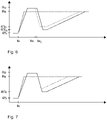
- 3 shows the behavior of the repetition rate R for different temperatures.
- the repetition rate is plotted against the ordinate in FIG. time is plotted against the abscissa.
- the user presses the operating button 12.
- the operating button 12 changes from the off position to the or one of the on positions.
- the device controller 20 detects the depressed position at time t2 (S1).
- the striking mechanism 5 is now activated.
- the device controller 20 detects the temperature T from the temperature sensor 22 and compares the temperature T with a limit temperature Tc (S2).
- the limit temperature Tc is e.g. below 10°C, e.g. at 10°C, 5°C, 0°C, -5°C, -10°C.
- the limit temperature Tc can be set, inter alia, depending on the lubricating oil used in the hammer mechanism 5 .
- the exciter 13 starts to move back and forth.
- the exciter 13 is indirectly accelerated (S3), in the example by the electric motor 8.
- the repetition rate R increases up to the setpoint repetition rate 21.
- the target repetition rate R is specified for a percussion mechanism 5 and typically the efficiency or the percussion power of the percussion mechanism 5 is highest at the repetition rate R.
- Typical target repetition rates of hand-held hammer drills range between 30 cycles per second (Hz) for larger hammer mechanisms and 150 Hz for smaller hammer mechanisms.
- the further behavior of the rotary hammer 1 depends on the application and the use by the user (S5).
- the course of the repetition rate R is in 3 shown dashed.
- the target repetition rate R is preferably reached as quickly as possible.
- a power consumption P of the percussion mechanism 5, in this example the power consumption of the driving electric motor 8, is preferably not limited by a control or regulation.
- the exciter 13 and the electric motor 8 accelerate with the maximum characteristic values Pmax of the rotary hammer 1.
- the target repetition rate R is reached, for example, in a duration t1 of preferably less than 1 s, e.g. less than 0.5 s, less than 0.2 s .
- the Schlagtechnik 5 is fully operational in less than 10 cycles.
- the switch-on process is now divided into two phases.
- the exciter 13 is accelerated to a repetition rate with a temperature-dependent intermediate value RTc.
- the intermediate value RTc is above 20%, eg above 40%, 60%, below 80%, eg below 70% of the target repetition rate 21.
- the intermediate value RTc can decrease as the temperature T increases.
- the intermediate value RTc2 for -10 °C is lower than the intermediate value RT1c for -5 °C.
- the intermediate values RTc are larger as the minimum repetition rate from which, at least at room temperature (20° C.), the racket 14 can follow the movement of the exciter 13 .
- the racket 14 is already beginning to follow the movement of the exciter 13 . Due to the low repetition rate R , the deflection of the racquet 14 is still low and the impact energy is correspondingly low.
- the intermediate value RTc is preferably reached as quickly as possible.
- a power consumption P of the percussion mechanism 5, in this example the power consumption of the driving electric motor 8, is preferably not limited by a control or regulation.
- the exciter 13 and the electric motor 8 accelerate with the maximum characteristic values Pmax of the rotary hammer 1 (S6).
- the intermediate value RTc is reached, for example, in a period of preferably less than 1 s, for example less than 0.5 s, less than 0.2 s.
- the second phase begins.
- the power consumption P of the percussion mechanism 5 is reduced to a lower value PTc (S8).
- the acceleration of the exciter 13 is significantly lower in the second phase than in the first phase. Acceleration can be less than a factor of ten.
- the exciter 13 can require more than 5 s, for example more than 10 s, until the target repetition rate 21 is reached. According to the invention, the exciter 13 only reaches the desired repetition rate 21 after 200 cycles, for example after 500 cycles. The user clearly perceives the change in the switch-on process.
- the course of the repetition rate R is in 3 shown as a solid line for two different temperatures.
- a variation of the switch-on process is in 4 shown.
- the process is essentially as to 2 described.
- the hammer drill 1 has a vibration sensor 23.
- the device control 20 checks whether the vibration values exceed a vibration limit value. Provided that the vibration levels do not exceed the vibration limit, the control method is no different from 2 . If the vibration limit is exceeded, for example at time t3, the acceleration of the exciter 13 is increased. The exciter 13 can be accelerated up to the target repetition rate 21 with the maximum acceleration, ie unlimited power consumption Pmax .
- the switch-on process can be shortened as a result.
- figure 5 shows an example control scheme of the device controller 20.
- 6 shows the behavior of the repetition rate R for different temperatures.
- the repetition rate is in plotted against the ordinate; time is plotted against the abscissa.
- the user presses the operating button 12.
- the operating button 12 changes from the off position to the or one of the on positions.
- the device controller 20 detects the depressed position at time t2 (S1).
- the striking mechanism 5 is now activated.
- the device controller 20 detects the temperature T from the temperature sensor 22 and compares the temperature T with a limit temperature Tc (S2).
- the limit temperature Tc is, for example, below 10°C, for example at 10°C, 5°C, 0°C, -5°C, -10°C.
- the limit temperature Tc can be set, inter alia, depending on the lubricating oil used in the hammer mechanism 5 .
- the behavior is the same as in the methods described above.
- the exciter 13 is accelerated as quickly as possible to the target repetition rate R (S3).
- the target repetition rate 21 (S4) is reached, the rotary hammer 1 is fully operational and the switching-on process is complete.
- the further behavior of the rotary hammer 1 depends on the application and the use by the user (S5).
- the course of the repetition rate R is in 6 shown dashed.
- the switch-on process is divided into two phases.
- the exciter 13 is accelerated to the maximum (S10).
- the power consumption P of the percussion mechanism 5 is not limited.
- the exciter 13 is accelerated until it reaches a preset value Ro .
- the default value Ro is in the range between 80% and 150% of the target repetition rate 21.
- the default value Ro is temperature-independent. Because of the maximum acceleration, the default value Ro is reached, for example, in a period of preferably less than 1 s, for example less than 0.5 s, less than 0.2 s.
- the exciter 13 is moved, no movement of the racquet 14 is to be expected. Subsequently, the exciter 13 is moved for a predetermined holding time with the set value Ro (S12).
- the holding time can be between 2 s and 20 s.
- the holding time is preferably temperature dependent.
- the holding time decreases with increasing temperature T. 6 shows the behavior for a temperature at -5°C (dotted) and at -10°C (solid).
- the repetition rate R is reduced.
- the repetition rate R is reduced to the temperature-dependent intermediate value RTc .
- the Power consumption P are set to zero (S13), whereby the percussion mechanism 5 expires and rapidly slows down.
- the power consumption P can be reduced to such an extent that the power consumption no longer compensates for friction losses and thermal losses.
- the impact mechanism 5 can also be actively braked. Reduction of the repetition rate R is terminated when the intermediate value RTc is reached.
- the intermediate value RTc can be chosen in the same way as in the previous examples.
- the first phase is followed by the second phase, which proceeds in the same way as in the previous examples.
- the power consumption P is increased to a temperature-dependent value PTc (S8).
- the exciter 13 is continuously accelerated until the target repetition rate 21 is reached (S9). Then the switch-on process is complete.
- the hammer drill 1 can have a vibration sensor 23 .
- the device controller 20 checks in a variant of the method of figure 5 while reducing the repetition rate R (S13/S14), whether vibrations exceed a vibration threshold. Provided that the vibration limit is not exceeded, the procedure runs as in figure 5 shown. 7 illustrates this behavior in the solid line. If the vibration limit value is exceeded, the reduction in the repetition rate R is terminated prematurely before the temperature-dependent intermediate value RTc is reached. The exciter 13 is immediately accelerated to the target repetition rate 21 according to the second phase, ie steps S8 and S9 .
Landscapes
- Engineering & Computer Science (AREA)
- Mechanical Engineering (AREA)
- Percussive Tools And Related Accessories (AREA)
Claims (10)
- Procédé de commande d'une machine-outil à main à percussion (1), ledit procédé comprenant les étapes suivantesdétecter un état de commutation d'un bouton de commande (12),détecter une température (T) à l'aide d'un capteur de température (22),activer un mécanisme de percussion électropneumatique (5) en réponse à l'actionnement du bouton de commande (12), un excitateur (13) du mécanisme de percussion électropneumatique (5) étant déplacé suivant un mouvement alternatif le long d'un axe de travail (3) à une fréquence de répétition (R), ce qui déplace conjointement un percuteur (14) accouplé à l'excitateur (13) par le biais d'une chambre pneumatique (16),caractérisé en ce quesi la température (T) est supérieure à une température limite (Tc), la fréquence de répétition (R) est augmentée de manière continue depuis le repos jusqu'à une valeur cible (21) et le nombre de cycles de l'excitateur (13), jusqu'à ce que la valeur cible (21) soit atteinte, est inférieur à 10 cycles, et en ce quesi la température (T) est inférieure à la température limite (Tc), le nombre de cycles de l'excitateur (13) depuis le repos jusqu'à ce que la valeur cible (21) soit atteinte, est supérieur à 200 cycles.
- Procédé de commande selon la revendication 1, caractérisé en ce que, lorsque la température (T) est supérieure à la température limite (Tc), la fréquence de répétition (R) est augmentée de manière continue avec une première accélération et, lorsque la température (T) est inférieure à la température limite (Tc), une valeur intermédiaire (RTc) est commandée dans une première phase, la fréquence de répétition (R) étant augmentée au moins par portions avec la première accélération, et dans une deuxième phase la fréquence de répétition (R) est augmentée de manière continue jusqu'à la valeur cible (21) avec une deuxième accélération.
- Procédé de commande selon la revendication 2, caractérisé en ce que la deuxième accélération est inférieure à 1/10 de la première accélération.
- Procédé de commande selon la revendication 2 ou 3, caractérisé en ce que dans la première phase la fréquence de répétition (R) est augmentée de manière continue depuis le repos jusqu'à la valeur intermédiaire (RTc) avec la première accélération puis dans la deuxième phase la fréquence de répétition (R) est augmentée de manière continue jusqu'à la valeur cible (21) avec la deuxième accélération.
- Procédé de commande selon la revendication 1 ou 3, caractérisé en ce que dans la première phase la fréquence de répétition (R) est augmentée depuis le repos jusqu'à une valeur par défaut (Ro) avec la première accélération et la fréquence de répétition (R) est abaissée depuis la valeur par défaut (Ro) jusqu'à la valeur intermédiaire (RTc), puis dans la deuxième phase la fréquence de répétition (R) est augmentée de manière continue jusqu'à la valeur cible (21) avec la deuxième accélération.
- Procédé de commande selon la revendication 5, caractérisé en ce que la valeur par défaut (Ro) est comprise entre 80 % et 150 % de la valeur cible (21).
- Procédé de commande selon l'une des revendications précédentes 2 à 6, caractérisé en ce que la valeur intermédiaire (RTc) est réglée en fonction de la température (T).
- Procédé de commande selon l'une des revendications précédentes 2 à 7, caractérisé en ce que pour la première accélération le mécanisme de percussion (5) est accéléré avec une puissance consommée maximale (Pmax).
- Procédé de commande selon l'une des revendications précédentes 2 à 8, caractérisé en ce que la valeur intermédiaire dépendant de la température (RTc) est comprise entre 20 % et 80 % de la valeur cible (21).
- Procédé de commande selon l'une des revendications précédentes 2 à 9, caractérisé en ce que la valeur cible (21) est comprise entre 30 cycles par seconde et 150 cycles par seconde.
Applications Claiming Priority (2)
| Application Number | Priority Date | Filing Date | Title |
|---|---|---|---|
| EP16203920.0A EP3335837A1 (fr) | 2016-12-14 | 2016-12-14 | Procédé de commande pour une machine-outil manuelle à percussion |
| PCT/EP2017/081634 WO2018108658A1 (fr) | 2016-12-14 | 2017-12-06 | Procédé de commande pour une machine-outil portative à percussion |
Publications (2)
| Publication Number | Publication Date |
|---|---|
| EP3554765A1 EP3554765A1 (fr) | 2019-10-23 |
| EP3554765B1 true EP3554765B1 (fr) | 2022-06-01 |
Family
ID=57629269
Family Applications (2)
| Application Number | Title | Priority Date | Filing Date |
|---|---|---|---|
| EP16203920.0A Withdrawn EP3335837A1 (fr) | 2016-12-14 | 2016-12-14 | Procédé de commande pour une machine-outil manuelle à percussion |
| EP17808505.6A Active EP3554765B1 (fr) | 2016-12-14 | 2017-12-06 | Procédé de commande pour une machine-outil manuelle de frappe |
Family Applications Before (1)
| Application Number | Title | Priority Date | Filing Date |
|---|---|---|---|
| EP16203920.0A Withdrawn EP3335837A1 (fr) | 2016-12-14 | 2016-12-14 | Procédé de commande pour une machine-outil manuelle à percussion |
Country Status (6)
| Country | Link |
|---|---|
| US (1) | US12115635B2 (fr) |
| EP (2) | EP3335837A1 (fr) |
| JP (1) | JP6845935B2 (fr) |
| KR (1) | KR102406100B1 (fr) |
| CN (1) | CN110072672B (fr) |
| WO (1) | WO2018108658A1 (fr) |
Families Citing this family (6)
| Publication number | Priority date | Publication date | Assignee | Title |
|---|---|---|---|---|
| US10040182B2 (en) * | 2014-01-21 | 2018-08-07 | Engineered Inserts & Systems, Inc. | System and method for installing a manifold plug |
| CN213259295U (zh) | 2017-10-20 | 2021-05-25 | 米沃奇电动工具公司 | 用于通过凿子在工件上执行开凿操作的冲击工具 |
| EP4349534A3 (fr) | 2018-01-26 | 2024-07-17 | Milwaukee Electric Tool Corporation | Outil à percussion |
| CN110774236B (zh) * | 2019-11-20 | 2021-07-27 | 山东奥德燃气设备制造有限公司 | 一种压力可调的气动冲击工具 |
| EP3960379A1 (fr) | 2020-08-31 | 2022-03-02 | Hilti Aktiengesellschaft | Machine-outil portative |
| EP4431241A1 (fr) | 2023-03-16 | 2024-09-18 | Hilti Aktiengesellschaft | Commande de démarrage à froid d'un outil électrique |
Family Cites Families (22)
| Publication number | Priority date | Publication date | Assignee | Title |
|---|---|---|---|---|
| JP3379439B2 (ja) * | 1997-09-17 | 2003-02-24 | トヨタ自動車株式会社 | 内燃機関の始動制御装置 |
| DE19843644B4 (de) * | 1998-09-23 | 2004-03-25 | Wacker Construction Equipment Ag | Rohrschlagwerk mit Rückholluftfeder |
| JP3521873B2 (ja) * | 2001-01-17 | 2004-04-26 | トヨタ自動車株式会社 | 車両用自動変速機の油圧制御装置 |
| US8047302B2 (en) * | 2001-12-21 | 2011-11-01 | Wacker Neuson Produktion GmbH & Co. KG | Drilling and/or striking hammer with a lubricating device |
| US7552781B2 (en) * | 2004-10-20 | 2009-06-30 | Black & Decker Inc. | Power tool anti-kickback system with rotational rate sensor |
| EP1674213B1 (fr) * | 2004-12-23 | 2008-10-01 | BLACK & DECKER INC. | Outil motorisé avec un dispositif de refroidissement |
| US7980324B2 (en) * | 2006-02-03 | 2011-07-19 | Black & Decker Inc. | Housing and gearbox for drill or driver |
| DE102007027898A1 (de) * | 2007-06-18 | 2008-12-24 | Robert Bosch Gmbh | Elektrowerkzeug mit Kaltstartfunktion |
| DE102008000909A1 (de) * | 2008-04-01 | 2009-10-08 | Hilti Aktiengesellschaft | Brennkraftbetriebenes Setzgerät |
| JP5193259B2 (ja) * | 2010-09-14 | 2013-05-08 | 株式会社日立カーエンジニアリング | 電動オイルポンプ用モータ制御装置及び制御方法 |
| JP2012076160A (ja) * | 2010-09-30 | 2012-04-19 | Hitachi Koki Co Ltd | 電動工具 |
| DE102011088974A1 (de) * | 2011-12-19 | 2013-06-20 | Continental Automotive Gmbh | Verfahren zur Anlaufsteuerung einer elektrischen Unterdruckpumpe |
| DE102012206452A1 (de) | 2012-04-19 | 2013-10-24 | Hilti Aktiengesellschaft | Handwerkzeugmaschine und Steuerungsverfahren |
| DE102012208902A1 (de) * | 2012-05-25 | 2013-11-28 | Robert Bosch Gmbh | Schlagwerkeinheit |
| DE102012208913A1 (de) * | 2012-05-25 | 2013-11-28 | Robert Bosch Gmbh | Schlagwerkeinheit |
| DE102012208870A1 (de) * | 2012-05-25 | 2013-11-28 | Robert Bosch Gmbh | Schlagwerkeinheit |
| EP2855098B1 (fr) * | 2012-05-25 | 2017-03-01 | Robert Bosch GmbH | Unité de percussion |
| EP2871028A1 (fr) * | 2013-11-11 | 2015-05-13 | HILTI Aktiengesellschaft | Machine-outil manuelle |
| DE102014207434A1 (de) * | 2014-04-17 | 2015-10-22 | Robert Bosch Gmbh | Verfahren zum Betreiben einer Handwerkzeugmaschine, Handwerkzeugmaschine |
| EP3009236A1 (fr) | 2014-10-16 | 2016-04-20 | HILTI Aktiengesellschaft | Machine-outil portative de burinage |
| JP2016112639A (ja) * | 2014-12-15 | 2016-06-23 | 株式会社マキタ | 動力工具 |
| EP3540224B1 (fr) * | 2016-11-14 | 2021-05-12 | TBK Co., Ltd. | Appareil de type pompe électrique |
-
2016
- 2016-12-14 EP EP16203920.0A patent/EP3335837A1/fr not_active Withdrawn
-
2017
- 2017-12-06 JP JP2019529852A patent/JP6845935B2/ja active Active
- 2017-12-06 KR KR1020197020092A patent/KR102406100B1/ko active Active
- 2017-12-06 CN CN201780077004.1A patent/CN110072672B/zh active Active
- 2017-12-06 US US16/469,008 patent/US12115635B2/en active Active
- 2017-12-06 EP EP17808505.6A patent/EP3554765B1/fr active Active
- 2017-12-06 WO PCT/EP2017/081634 patent/WO2018108658A1/fr not_active Ceased
Also Published As
| Publication number | Publication date |
|---|---|
| WO2018108658A1 (fr) | 2018-06-21 |
| JP6845935B2 (ja) | 2021-03-24 |
| EP3335837A1 (fr) | 2018-06-20 |
| JP2020500725A (ja) | 2020-01-16 |
| CN110072672B (zh) | 2022-05-06 |
| KR20190093645A (ko) | 2019-08-09 |
| KR102406100B1 (ko) | 2022-06-10 |
| US20190314970A1 (en) | 2019-10-17 |
| CN110072672A (zh) | 2019-07-30 |
| US12115635B2 (en) | 2024-10-15 |
| EP3554765A1 (fr) | 2019-10-23 |
Similar Documents
| Publication | Publication Date | Title |
|---|---|---|
| EP3554765B1 (fr) | Procédé de commande pour une machine-outil manuelle de frappe | |
| EP1893388B1 (fr) | Marteau perforateur et/ou marteau pneumatique a commande de la marche a vide | |
| EP2986421B1 (fr) | Appareil de rivetage | |
| EP2855095B1 (fr) | Unité de percussion | |
| EP2140976B1 (fr) | Vis autotaraudeuse à frapper | |
| DE112014003403B4 (de) | Hin- und herbewegendes elektrisches Kraftwerkzeug | |
| EP2213420B1 (fr) | Procédé de commande et machine-outil manuelle | |
| EP1170095B1 (fr) | Outil à main électrique avec interruption de marche en vide | |
| EP2514567B1 (fr) | Outil d'enfoncement | |
| EP3377271A1 (fr) | Procédé de commande d'une machine-outil | |
| WO2013174600A1 (fr) | Unité de percussion | |
| DE102015013532A1 (de) | Elektrisches Kraftwerkzeug | |
| EP3199303A1 (fr) | Machine-outil portative | |
| WO2013139425A1 (fr) | Marteau perforateur et/ou à percussion s'adaptant selon la contrainte à la fréquence de percussion | |
| EP3180165B1 (fr) | Procéde optimisé pour une ancre extensible | |
| DE4328599A1 (de) | Rotations-Schlagwerkzeug | |
| EP2305434B1 (fr) | Machine-outil électrique | |
| EP2517839B1 (fr) | Machine-outil et procédé de commande | |
| EP0773854A1 (fr) | Visseuse et procede de serrage de vis | |
| EP3427899A1 (fr) | Machine-outil portative | |
| EP1632313B1 (fr) | Outil de serrage avec mécanisme d'impact axial | |
| EP1621290B1 (fr) | Machine-outil avec impulsion intermittent | |
| EP2921263A1 (fr) | Reconnaissance de comportement au choc en fonction de la charge | |
| DE102011088958A1 (de) | Werkzeugvorrichtung | |
| EP3323561A1 (fr) | Appareil de pose et procédé de fonctionnement d'un appareil de pose |
Legal Events
| Date | Code | Title | Description |
|---|---|---|---|
| STAA | Information on the status of an ep patent application or granted ep patent |
Free format text: STATUS: UNKNOWN |
|
| STAA | Information on the status of an ep patent application or granted ep patent |
Free format text: STATUS: THE INTERNATIONAL PUBLICATION HAS BEEN MADE |
|
| PUAI | Public reference made under article 153(3) epc to a published international application that has entered the european phase |
Free format text: ORIGINAL CODE: 0009012 |
|
| STAA | Information on the status of an ep patent application or granted ep patent |
Free format text: STATUS: REQUEST FOR EXAMINATION WAS MADE |
|
| 17P | Request for examination filed |
Effective date: 20190715 |
|
| AK | Designated contracting states |
Kind code of ref document: A1 Designated state(s): AL AT BE BG CH CY CZ DE DK EE ES FI FR GB GR HR HU IE IS IT LI LT LU LV MC MK MT NL NO PL PT RO RS SE SI SK SM TR |
|
| AX | Request for extension of the european patent |
Extension state: BA ME |
|
| DAV | Request for validation of the european patent (deleted) | ||
| DAX | Request for extension of the european patent (deleted) | ||
| GRAP | Despatch of communication of intention to grant a patent |
Free format text: ORIGINAL CODE: EPIDOSNIGR1 |
|
| STAA | Information on the status of an ep patent application or granted ep patent |
Free format text: STATUS: GRANT OF PATENT IS INTENDED |
|
| INTG | Intention to grant announced |
Effective date: 20220316 |
|
| GRAS | Grant fee paid |
Free format text: ORIGINAL CODE: EPIDOSNIGR3 |
|
| GRAA | (expected) grant |
Free format text: ORIGINAL CODE: 0009210 |
|
| STAA | Information on the status of an ep patent application or granted ep patent |
Free format text: STATUS: THE PATENT HAS BEEN GRANTED |
|
| AK | Designated contracting states |
Kind code of ref document: B1 Designated state(s): AL AT BE BG CH CY CZ DE DK EE ES FI FR GB GR HR HU IE IS IT LI LT LU LV MC MK MT NL NO PL PT RO RS SE SI SK SM TR |
|
| REG | Reference to a national code |
Ref country code: GB Ref legal event code: FG4D Free format text: NOT ENGLISH |
|
| REG | Reference to a national code |
Ref country code: AT Ref legal event code: REF Ref document number: 1495051 Country of ref document: AT Kind code of ref document: T Effective date: 20220615 Ref country code: CH Ref legal event code: EP Ref country code: DE Ref legal event code: R096 Ref document number: 502017013264 Country of ref document: DE |
|
| REG | Reference to a national code |
Ref country code: IE Ref legal event code: FG4D Free format text: LANGUAGE OF EP DOCUMENT: GERMAN |
|
| REG | Reference to a national code |
Ref country code: LT Ref legal event code: MG9D |
|
| REG | Reference to a national code |
Ref country code: NL Ref legal event code: MP Effective date: 20220601 |
|
| PG25 | Lapsed in a contracting state [announced via postgrant information from national office to epo] |
Ref country code: SE Free format text: LAPSE BECAUSE OF FAILURE TO SUBMIT A TRANSLATION OF THE DESCRIPTION OR TO PAY THE FEE WITHIN THE PRESCRIBED TIME-LIMIT Effective date: 20220601 Ref country code: NO Free format text: LAPSE BECAUSE OF FAILURE TO SUBMIT A TRANSLATION OF THE DESCRIPTION OR TO PAY THE FEE WITHIN THE PRESCRIBED TIME-LIMIT Effective date: 20220901 Ref country code: LT Free format text: LAPSE BECAUSE OF FAILURE TO SUBMIT A TRANSLATION OF THE DESCRIPTION OR TO PAY THE FEE WITHIN THE PRESCRIBED TIME-LIMIT Effective date: 20220601 Ref country code: HR Free format text: LAPSE BECAUSE OF FAILURE TO SUBMIT A TRANSLATION OF THE DESCRIPTION OR TO PAY THE FEE WITHIN THE PRESCRIBED TIME-LIMIT Effective date: 20220601 Ref country code: GR Free format text: LAPSE BECAUSE OF FAILURE TO SUBMIT A TRANSLATION OF THE DESCRIPTION OR TO PAY THE FEE WITHIN THE PRESCRIBED TIME-LIMIT Effective date: 20220902 Ref country code: FI Free format text: LAPSE BECAUSE OF FAILURE TO SUBMIT A TRANSLATION OF THE DESCRIPTION OR TO PAY THE FEE WITHIN THE PRESCRIBED TIME-LIMIT Effective date: 20220601 Ref country code: ES Free format text: LAPSE BECAUSE OF FAILURE TO SUBMIT A TRANSLATION OF THE DESCRIPTION OR TO PAY THE FEE WITHIN THE PRESCRIBED TIME-LIMIT Effective date: 20220601 Ref country code: BG Free format text: LAPSE BECAUSE OF FAILURE TO SUBMIT A TRANSLATION OF THE DESCRIPTION OR TO PAY THE FEE WITHIN THE PRESCRIBED TIME-LIMIT Effective date: 20220901 |
|
| PG25 | Lapsed in a contracting state [announced via postgrant information from national office to epo] |
Ref country code: RS Free format text: LAPSE BECAUSE OF FAILURE TO SUBMIT A TRANSLATION OF THE DESCRIPTION OR TO PAY THE FEE WITHIN THE PRESCRIBED TIME-LIMIT Effective date: 20220601 Ref country code: PL Free format text: LAPSE BECAUSE OF FAILURE TO SUBMIT A TRANSLATION OF THE DESCRIPTION OR TO PAY THE FEE WITHIN THE PRESCRIBED TIME-LIMIT Effective date: 20220601 Ref country code: LV Free format text: LAPSE BECAUSE OF FAILURE TO SUBMIT A TRANSLATION OF THE DESCRIPTION OR TO PAY THE FEE WITHIN THE PRESCRIBED TIME-LIMIT Effective date: 20220601 |
|
| PG25 | Lapsed in a contracting state [announced via postgrant information from national office to epo] |
Ref country code: NL Free format text: LAPSE BECAUSE OF FAILURE TO SUBMIT A TRANSLATION OF THE DESCRIPTION OR TO PAY THE FEE WITHIN THE PRESCRIBED TIME-LIMIT Effective date: 20220601 |
|
| PG25 | Lapsed in a contracting state [announced via postgrant information from national office to epo] |
Ref country code: SM Free format text: LAPSE BECAUSE OF FAILURE TO SUBMIT A TRANSLATION OF THE DESCRIPTION OR TO PAY THE FEE WITHIN THE PRESCRIBED TIME-LIMIT Effective date: 20220601 Ref country code: SK Free format text: LAPSE BECAUSE OF FAILURE TO SUBMIT A TRANSLATION OF THE DESCRIPTION OR TO PAY THE FEE WITHIN THE PRESCRIBED TIME-LIMIT Effective date: 20220601 Ref country code: RO Free format text: LAPSE BECAUSE OF FAILURE TO SUBMIT A TRANSLATION OF THE DESCRIPTION OR TO PAY THE FEE WITHIN THE PRESCRIBED TIME-LIMIT Effective date: 20220601 Ref country code: PT Free format text: LAPSE BECAUSE OF FAILURE TO SUBMIT A TRANSLATION OF THE DESCRIPTION OR TO PAY THE FEE WITHIN THE PRESCRIBED TIME-LIMIT Effective date: 20221003 Ref country code: EE Free format text: LAPSE BECAUSE OF FAILURE TO SUBMIT A TRANSLATION OF THE DESCRIPTION OR TO PAY THE FEE WITHIN THE PRESCRIBED TIME-LIMIT Effective date: 20220601 Ref country code: CZ Free format text: LAPSE BECAUSE OF FAILURE TO SUBMIT A TRANSLATION OF THE DESCRIPTION OR TO PAY THE FEE WITHIN THE PRESCRIBED TIME-LIMIT Effective date: 20220601 |
|
| PG25 | Lapsed in a contracting state [announced via postgrant information from national office to epo] |
Ref country code: IS Free format text: LAPSE BECAUSE OF FAILURE TO SUBMIT A TRANSLATION OF THE DESCRIPTION OR TO PAY THE FEE WITHIN THE PRESCRIBED TIME-LIMIT Effective date: 20221001 |
|
| REG | Reference to a national code |
Ref country code: DE Ref legal event code: R097 Ref document number: 502017013264 Country of ref document: DE |
|
| PG25 | Lapsed in a contracting state [announced via postgrant information from national office to epo] |
Ref country code: AL Free format text: LAPSE BECAUSE OF FAILURE TO SUBMIT A TRANSLATION OF THE DESCRIPTION OR TO PAY THE FEE WITHIN THE PRESCRIBED TIME-LIMIT Effective date: 20220601 |
|
| PLBE | No opposition filed within time limit |
Free format text: ORIGINAL CODE: 0009261 |
|
| STAA | Information on the status of an ep patent application or granted ep patent |
Free format text: STATUS: NO OPPOSITION FILED WITHIN TIME LIMIT |
|
| PG25 | Lapsed in a contracting state [announced via postgrant information from national office to epo] |
Ref country code: DK Free format text: LAPSE BECAUSE OF FAILURE TO SUBMIT A TRANSLATION OF THE DESCRIPTION OR TO PAY THE FEE WITHIN THE PRESCRIBED TIME-LIMIT Effective date: 20220601 |
|
| 26N | No opposition filed |
Effective date: 20230302 |
|
| PG25 | Lapsed in a contracting state [announced via postgrant information from national office to epo] |
Ref country code: SI Free format text: LAPSE BECAUSE OF FAILURE TO SUBMIT A TRANSLATION OF THE DESCRIPTION OR TO PAY THE FEE WITHIN THE PRESCRIBED TIME-LIMIT Effective date: 20220601 |
|
| REG | Reference to a national code |
Ref country code: CH Ref legal event code: PL |
|
| REG | Reference to a national code |
Ref country code: BE Ref legal event code: MM Effective date: 20221231 |
|
| PG25 | Lapsed in a contracting state [announced via postgrant information from national office to epo] |
Ref country code: LU Free format text: LAPSE BECAUSE OF NON-PAYMENT OF DUE FEES Effective date: 20221206 |
|
| P01 | Opt-out of the competence of the unified patent court (upc) registered |
Effective date: 20230830 |
|
| PG25 | Lapsed in a contracting state [announced via postgrant information from national office to epo] |
Ref country code: LI Free format text: LAPSE BECAUSE OF NON-PAYMENT OF DUE FEES Effective date: 20221231 Ref country code: IE Free format text: LAPSE BECAUSE OF NON-PAYMENT OF DUE FEES Effective date: 20221206 Ref country code: CH Free format text: LAPSE BECAUSE OF NON-PAYMENT OF DUE FEES Effective date: 20221231 |
|
| PG25 | Lapsed in a contracting state [announced via postgrant information from national office to epo] |
Ref country code: BE Free format text: LAPSE BECAUSE OF NON-PAYMENT OF DUE FEES Effective date: 20221231 |
|
| REG | Reference to a national code |
Ref country code: AT Ref legal event code: MM01 Ref document number: 1495051 Country of ref document: AT Kind code of ref document: T Effective date: 20221206 |
|
| PG25 | Lapsed in a contracting state [announced via postgrant information from national office to epo] |
Ref country code: HU Free format text: LAPSE BECAUSE OF FAILURE TO SUBMIT A TRANSLATION OF THE DESCRIPTION OR TO PAY THE FEE WITHIN THE PRESCRIBED TIME-LIMIT; INVALID AB INITIO Effective date: 20171206 |
|
| PG25 | Lapsed in a contracting state [announced via postgrant information from national office to epo] |
Ref country code: AT Free format text: LAPSE BECAUSE OF NON-PAYMENT OF DUE FEES Effective date: 20221206 |
|
| PG25 | Lapsed in a contracting state [announced via postgrant information from national office to epo] |
Ref country code: CY Free format text: LAPSE BECAUSE OF FAILURE TO SUBMIT A TRANSLATION OF THE DESCRIPTION OR TO PAY THE FEE WITHIN THE PRESCRIBED TIME-LIMIT Effective date: 20220601 Ref country code: AT Free format text: LAPSE BECAUSE OF NON-PAYMENT OF DUE FEES Effective date: 20221206 |
|
| PG25 | Lapsed in a contracting state [announced via postgrant information from national office to epo] |
Ref country code: MK Free format text: LAPSE BECAUSE OF FAILURE TO SUBMIT A TRANSLATION OF THE DESCRIPTION OR TO PAY THE FEE WITHIN THE PRESCRIBED TIME-LIMIT Effective date: 20220601 |
|
| PG25 | Lapsed in a contracting state [announced via postgrant information from national office to epo] |
Ref country code: MC Free format text: LAPSE BECAUSE OF FAILURE TO SUBMIT A TRANSLATION OF THE DESCRIPTION OR TO PAY THE FEE WITHIN THE PRESCRIBED TIME-LIMIT Effective date: 20220601 |
|
| PG25 | Lapsed in a contracting state [announced via postgrant information from national office to epo] |
Ref country code: MC Free format text: LAPSE BECAUSE OF FAILURE TO SUBMIT A TRANSLATION OF THE DESCRIPTION OR TO PAY THE FEE WITHIN THE PRESCRIBED TIME-LIMIT Effective date: 20220601 |
|
| PG25 | Lapsed in a contracting state [announced via postgrant information from national office to epo] |
Ref country code: MT Free format text: LAPSE BECAUSE OF FAILURE TO SUBMIT A TRANSLATION OF THE DESCRIPTION OR TO PAY THE FEE WITHIN THE PRESCRIBED TIME-LIMIT Effective date: 20220601 |
|
| PG25 | Lapsed in a contracting state [announced via postgrant information from national office to epo] |
Ref country code: BG Free format text: LAPSE BECAUSE OF FAILURE TO SUBMIT A TRANSLATION OF THE DESCRIPTION OR TO PAY THE FEE WITHIN THE PRESCRIBED TIME-LIMIT Effective date: 20220601 |
|
| PG25 | Lapsed in a contracting state [announced via postgrant information from national office to epo] |
Ref country code: BG Free format text: LAPSE BECAUSE OF FAILURE TO SUBMIT A TRANSLATION OF THE DESCRIPTION OR TO PAY THE FEE WITHIN THE PRESCRIBED TIME-LIMIT Effective date: 20220601 |
|
| PG25 | Lapsed in a contracting state [announced via postgrant information from national office to epo] |
Ref country code: TR Free format text: LAPSE BECAUSE OF FAILURE TO SUBMIT A TRANSLATION OF THE DESCRIPTION OR TO PAY THE FEE WITHIN THE PRESCRIBED TIME-LIMIT Effective date: 20220601 |
|
| PGFP | Annual fee paid to national office [announced via postgrant information from national office to epo] |
Ref country code: DE Payment date: 20251211 Year of fee payment: 9 |
|
| PGFP | Annual fee paid to national office [announced via postgrant information from national office to epo] |
Ref country code: GB Payment date: 20251219 Year of fee payment: 9 |
|
| PGFP | Annual fee paid to national office [announced via postgrant information from national office to epo] |
Ref country code: IT Payment date: 20251223 Year of fee payment: 9 |
|
| PGFP | Annual fee paid to national office [announced via postgrant information from national office to epo] |
Ref country code: FR Payment date: 20251229 Year of fee payment: 9 |