EP3554765B1 - Steuerungsverfahren für eine schlagende handwerkzeugmaschine - Google Patents
Steuerungsverfahren für eine schlagende handwerkzeugmaschine Download PDFInfo
- Publication number
- EP3554765B1 EP3554765B1 EP17808505.6A EP17808505A EP3554765B1 EP 3554765 B1 EP3554765 B1 EP 3554765B1 EP 17808505 A EP17808505 A EP 17808505A EP 3554765 B1 EP3554765 B1 EP 3554765B1
- Authority
- EP
- European Patent Office
- Prior art keywords
- repetition rate
- temperature
- control method
- acceleration
- exciter
- Prior art date
- Legal status (The legal status is an assumption and is not a legal conclusion. Google has not performed a legal analysis and makes no representation as to the accuracy of the status listed.)
- Active
Links
Images


Classifications
-
- B—PERFORMING OPERATIONS; TRANSPORTING
- B25—HAND TOOLS; PORTABLE POWER-DRIVEN TOOLS; MANIPULATORS
- B25D—PERCUSSIVE TOOLS
- B25D11/00—Portable percussive tools with electromotor or other motor drive
-
- B—PERFORMING OPERATIONS; TRANSPORTING
- B25—HAND TOOLS; PORTABLE POWER-DRIVEN TOOLS; MANIPULATORS
- B25D—PERCUSSIVE TOOLS
- B25D11/00—Portable percussive tools with electromotor or other motor drive
- B25D11/06—Means for driving the impulse member
-
- B—PERFORMING OPERATIONS; TRANSPORTING
- B25—HAND TOOLS; PORTABLE POWER-DRIVEN TOOLS; MANIPULATORS
- B25D—PERCUSSIVE TOOLS
- B25D2216/00—Details of portable percussive machines with superimposed rotation, the rotational movement of the output shaft of a motor being modified to generate axial impacts on the tool bit
- B25D2216/0007—Details of percussion or rotation modes
- B25D2216/0015—Tools having a percussion-only mode
-
- B—PERFORMING OPERATIONS; TRANSPORTING
- B25—HAND TOOLS; PORTABLE POWER-DRIVEN TOOLS; MANIPULATORS
- B25D—PERCUSSIVE TOOLS
- B25D2250/00—General details of portable percussive tools; Components used in portable percussive tools
- B25D2250/195—Regulation means
- B25D2250/201—Regulation means for speed, e.g. drilling or percussion speed
-
- B—PERFORMING OPERATIONS; TRANSPORTING
- B25—HAND TOOLS; PORTABLE POWER-DRIVEN TOOLS; MANIPULATORS
- B25D—PERCUSSIVE TOOLS
- B25D2250/00—General details of portable percussive tools; Components used in portable percussive tools
- B25D2250/221—Sensors
Definitions
- the present invention relates to control methods for a percussive power tool, in particular a hand-held pneumatic hammer drill and a hand-held pneumatic electric chisel.
- the hammer mechanism of a rotary hammer heats up during operation due to the friction of moving components and thermal losses in the air spring.
- the operating temperature is between 80 °C and 150 °C.
- Lubrication, seals, dimensions and tolerances of the impact mechanism are designed with regard to the typical operating temperature.
- the impact mechanism is cold, especially in cold working environments below freezing. The conditions are not optimal for the impact mechanism and can prevent the impact mechanism from starting reliably.
- a control method for a percussive handheld power tool according to claim 1 has the steps: detecting a switching state of an operating button, detecting a temperature with a temperature sensor, activating an electro-pneumatic impact mechanism in response to the operating button being actuated, with an exciter of the electro-pneumatic impact mechanism moving along a The working axis is moved back and forth at a repetition rate R, which moves a beater coupled to the exciter via a pneumatic chamber. If the temperature is greater than a limit temperature, the repetition rate is continuously increased from rest to a setpoint. A number of exciter cycles until the target value is reached is less than 10 cycles. If the temperature is less than the limit temperature, a number of cycles of the exciter to reach the setpoint is greater than 200 cycles.
- the repetition rate is continuously increased with a first acceleration. Otherwise, if the temperature is lower than the limit temperature, in a first phase a Driven intermediate value, the repetition rate is increased at least in sections with the first acceleration, and in a second phase, the repetition rate with a second acceleration up to the setpoint continuously increased.
- the second acceleration can be less than 1/10 of the first acceleration.
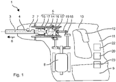
- the rotary hammer 1 shows a hammer drill 1 as an example of a percussive hand-held machine tool.
- the rotary hammer 1 has a tool holder 2, in which a drill, chisel or other striking tool 4 can be used and locked coaxially to a working axis 3 .
- the hammer drill 1 has a pneumatic impact mechanism 5 which can periodically strike the tool 4 in an impact direction 6 .
- a rotary drive 7 can continuously rotate the tool holder 2 about the working axis 3 .
- the pneumatic percussion mechanism 5 and the rotary drive are driven by an electric motor 8 , which is fed with electricity from a battery 9 or a mains line.
- the hammer mechanism 5 and the rotary drive 7 are arranged in a machine housing 10 .
- a handle 11 is typically arranged on a side of the machine housing 10 facing away from the tool holder 2 .
- the user can use the handle 11 to hold and guide the rotary hammer 1 during operation.
- An additional auxiliary handle can be attached near the tool holder 2 .
- On or near the handle 11 is a Operating button 12 arranged, which the user can preferably operate with the holding hand.
- the electric motor 8 is switched on by pressing the operating button 12 . Typically, the electric motor 8 rotates as long as the operating button 12 is held down.
- the pneumatic hammer mechanism 5 has an exciter 13, a hammer 14 and optionally a die 15 along the direction of impact 6.
- the exciter 13 is forced to move periodically along the working axis 3 by means of the electric motor 8 .
- the beater 14 couples to the movement of the exciter 13 via an air spring.
- the air spring is formed by a closed pneumatic chamber 16 between the exciter 13 and the beater 14 .
- the bat 14 moves in the direction of impact 6 until the bat 14 hits the die 15 .
- the die 15 rests against the tool 4 in the impact direction 6 and transfers the impact to the tool 4.
- the exemplary percussion mechanism 5 has a piston-shaped exciter 13 and a piston-shaped hammer 14 which are guided along the working axis 3 through a guide tube 17 .
- the exciter 13 and the beater 14 bear against the inner surface of the guide tube 17 with their lateral surfaces.
- the pneumatic chamber 16 is closed off by the exciter 13 and the beater 14 along the working axis 3 and by the guide tube 17 in the radial direction. Sealing rings in the lateral surfaces of the exciter 13 and the beater 14 can improve the airtight closure of the pneumatic chamber 16 .
- the exciter 13 is connected to the electric motor 8 via a transmission component.
- the gear component transfers the rotational movement of the electric motor 8 into a periodic translational movement along the working axis 3.
- An exemplary gear component is based on an eccentric wheel 18 which is connected to the electric motor 8 .
- a connecting rod 19 connects the eccentric wheel 18 to the exciter 13.
- the exciter 13 moves synchronously with the electric motor 8.
- the electric motor 8 typically rotates in response to the operation button 12 being pressed and continues to rotate as long as the user keeps the operation button 12 pressed.
- the periodic forward and backward movement of the exciter 13 also begins and ends when the operating button 12 is actuated or released.
- Another example of such a transmission component is a wobble drive.
- the exciter 13 moves at a repetition rate R which is proportional to the speed of the electric motor 8 .
- the transmission components between the electric motor 8 and the exciter 13 typically have a step-down effect in a fixed ratio.
- the repetition rate R is in the range, for example, between 30 cycles per second (Hz) and 150 Hz.
- the beater 14 is coupled to the exciter 13 by the pneumatic chamber 16 and moves at the same repetition rate as the exciter 13.
- the beater 14 is coupled to the exciter 13 exclusively via an air spring.
- the air spring is based on a pressure difference between the pressure in the pneumatic chamber 16 and the pressure in the environment.
- the positively moved exciter 13 increases or decreases the pressure in the pneumatic chamber 16 by means of its periodic axial movement.
- the hammer 14 is accelerated by the pressure difference in the direction of impact 6 or counter to the direction of impact 6 .
- the hammer drill 1 has a device control 20 which specifies the repetition rate R of the exciter 13 .
- the device controller 20 controls the electric motor 8 .
- the electric motor 8 contains a speed controller, for which a target value for the speed is specified by the device controller 20 .
- Speed control can also be implemented in the implement controller 20 based on a speed sensor on the motor shaft and a negative feedback loop.
- the device controller 20 can limit a power consumption of the percussion mechanism 5 or a power consumption of the electric motor 8 in order to specify the repetition rate.
- the device controller 20 detects the position of the operating button 12.
- the operating button 12 has an off position, to which the device controller 20 responds by specifying a repetition rate of zero, ie the percussion mechanism 5 switches off.
- the operating button 12 has an on position, to which the device control 20 activates the percussion mechanism 5 in response.
- the electric motor 8 is accelerated up to a nominal value in order to obtain a specified target repetition rate 21 of the exciter 13 .
- the operation button 12 will automatically return from the on position to the off position if the operation button 12 is not held down.
- the repetition rate R is increased when the operating button 12 changes from the off position to the on position depending on a temperature T of the rotary hammer 1.
- a temperature sensor 22 in the machine housing 10 measures the current operating temperature T.
- the temperature sensor 22 can be attached to the hammer mechanism 5 or together with other electronics of the device control 20 can be arranged on a printed circuit board.
- FIG. 2 shows an example control scheme of the device controller 20.
- 3 shows the behavior of the repetition rate R for different temperatures.
- the repetition rate is plotted against the ordinate in FIG. time is plotted against the abscissa.
- the user presses the operating button 12.
- the operating button 12 changes from the off position to the or one of the on positions.
- the device controller 20 detects the depressed position at time t2 (S1).
- the striking mechanism 5 is now activated.
- the device controller 20 detects the temperature T from the temperature sensor 22 and compares the temperature T with a limit temperature Tc (S2).
- the limit temperature Tc is e.g. below 10°C, e.g. at 10°C, 5°C, 0°C, -5°C, -10°C.
- the limit temperature Tc can be set, inter alia, depending on the lubricating oil used in the hammer mechanism 5 .
- the exciter 13 starts to move back and forth.
- the exciter 13 is indirectly accelerated (S3), in the example by the electric motor 8.
- the repetition rate R increases up to the setpoint repetition rate 21.
- the target repetition rate R is specified for a percussion mechanism 5 and typically the efficiency or the percussion power of the percussion mechanism 5 is highest at the repetition rate R.
- Typical target repetition rates of hand-held hammer drills range between 30 cycles per second (Hz) for larger hammer mechanisms and 150 Hz for smaller hammer mechanisms.
- the further behavior of the rotary hammer 1 depends on the application and the use by the user (S5).
- the course of the repetition rate R is in 3 shown dashed.
- the target repetition rate R is preferably reached as quickly as possible.
- a power consumption P of the percussion mechanism 5, in this example the power consumption of the driving electric motor 8, is preferably not limited by a control or regulation.
- the exciter 13 and the electric motor 8 accelerate with the maximum characteristic values Pmax of the rotary hammer 1.
- the target repetition rate R is reached, for example, in a duration t1 of preferably less than 1 s, e.g. less than 0.5 s, less than 0.2 s .
- the Schlagtechnik 5 is fully operational in less than 10 cycles.
- the switch-on process is now divided into two phases.
- the exciter 13 is accelerated to a repetition rate with a temperature-dependent intermediate value RTc.
- the intermediate value RTc is above 20%, eg above 40%, 60%, below 80%, eg below 70% of the target repetition rate 21.
- the intermediate value RTc can decrease as the temperature T increases.
- the intermediate value RTc2 for -10 °C is lower than the intermediate value RT1c for -5 °C.
- the intermediate values RTc are larger as the minimum repetition rate from which, at least at room temperature (20° C.), the racket 14 can follow the movement of the exciter 13 .
- the racket 14 is already beginning to follow the movement of the exciter 13 . Due to the low repetition rate R , the deflection of the racquet 14 is still low and the impact energy is correspondingly low.
- the intermediate value RTc is preferably reached as quickly as possible.
- a power consumption P of the percussion mechanism 5, in this example the power consumption of the driving electric motor 8, is preferably not limited by a control or regulation.
- the exciter 13 and the electric motor 8 accelerate with the maximum characteristic values Pmax of the rotary hammer 1 (S6).
- the intermediate value RTc is reached, for example, in a period of preferably less than 1 s, for example less than 0.5 s, less than 0.2 s.
- the second phase begins.
- the power consumption P of the percussion mechanism 5 is reduced to a lower value PTc (S8).
- the acceleration of the exciter 13 is significantly lower in the second phase than in the first phase. Acceleration can be less than a factor of ten.
- the exciter 13 can require more than 5 s, for example more than 10 s, until the target repetition rate 21 is reached. According to the invention, the exciter 13 only reaches the desired repetition rate 21 after 200 cycles, for example after 500 cycles. The user clearly perceives the change in the switch-on process.
- the course of the repetition rate R is in 3 shown as a solid line for two different temperatures.
- a variation of the switch-on process is in 4 shown.
- the process is essentially as to 2 described.
- the hammer drill 1 has a vibration sensor 23.
- the device control 20 checks whether the vibration values exceed a vibration limit value. Provided that the vibration levels do not exceed the vibration limit, the control method is no different from 2 . If the vibration limit is exceeded, for example at time t3, the acceleration of the exciter 13 is increased. The exciter 13 can be accelerated up to the target repetition rate 21 with the maximum acceleration, ie unlimited power consumption Pmax .
- the switch-on process can be shortened as a result.
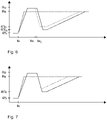
- figure 5 shows an example control scheme of the device controller 20.
- 6 shows the behavior of the repetition rate R for different temperatures.
- the repetition rate is in plotted against the ordinate; time is plotted against the abscissa.
- the user presses the operating button 12.
- the operating button 12 changes from the off position to the or one of the on positions.
- the device controller 20 detects the depressed position at time t2 (S1).
- the striking mechanism 5 is now activated.
- the device controller 20 detects the temperature T from the temperature sensor 22 and compares the temperature T with a limit temperature Tc (S2).
- the limit temperature Tc is, for example, below 10°C, for example at 10°C, 5°C, 0°C, -5°C, -10°C.
- the limit temperature Tc can be set, inter alia, depending on the lubricating oil used in the hammer mechanism 5 .
- the behavior is the same as in the methods described above.
- the exciter 13 is accelerated as quickly as possible to the target repetition rate R (S3).
- the target repetition rate 21 (S4) is reached, the rotary hammer 1 is fully operational and the switching-on process is complete.
- the further behavior of the rotary hammer 1 depends on the application and the use by the user (S5).
- the course of the repetition rate R is in 6 shown dashed.
- the switch-on process is divided into two phases.
- the exciter 13 is accelerated to the maximum (S10).
- the power consumption P of the percussion mechanism 5 is not limited.
- the exciter 13 is accelerated until it reaches a preset value Ro .
- the default value Ro is in the range between 80% and 150% of the target repetition rate 21.
- the default value Ro is temperature-independent. Because of the maximum acceleration, the default value Ro is reached, for example, in a period of preferably less than 1 s, for example less than 0.5 s, less than 0.2 s.
- the exciter 13 is moved, no movement of the racquet 14 is to be expected. Subsequently, the exciter 13 is moved for a predetermined holding time with the set value Ro (S12).
- the holding time can be between 2 s and 20 s.
- the holding time is preferably temperature dependent.
- the holding time decreases with increasing temperature T. 6 shows the behavior for a temperature at -5°C (dotted) and at -10°C (solid).
- the repetition rate R is reduced.
- the repetition rate R is reduced to the temperature-dependent intermediate value RTc .
- the Power consumption P are set to zero (S13), whereby the percussion mechanism 5 expires and rapidly slows down.
- the power consumption P can be reduced to such an extent that the power consumption no longer compensates for friction losses and thermal losses.
- the impact mechanism 5 can also be actively braked. Reduction of the repetition rate R is terminated when the intermediate value RTc is reached.
- the intermediate value RTc can be chosen in the same way as in the previous examples.
- the first phase is followed by the second phase, which proceeds in the same way as in the previous examples.
- the power consumption P is increased to a temperature-dependent value PTc (S8).
- the exciter 13 is continuously accelerated until the target repetition rate 21 is reached (S9). Then the switch-on process is complete.
- the hammer drill 1 can have a vibration sensor 23 .
- the device controller 20 checks in a variant of the method of figure 5 while reducing the repetition rate R (S13/S14), whether vibrations exceed a vibration threshold. Provided that the vibration limit is not exceeded, the procedure runs as in figure 5 shown. 7 illustrates this behavior in the solid line. If the vibration limit value is exceeded, the reduction in the repetition rate R is terminated prematurely before the temperature-dependent intermediate value RTc is reached. The exciter 13 is immediately accelerated to the target repetition rate 21 according to the second phase, ie steps S8 and S9 .
Landscapes
- Engineering & Computer Science (AREA)
- Mechanical Engineering (AREA)
- Percussive Tools And Related Accessories (AREA)
Description
- Die vorliegende Erfindung betrifft Steuerungsverfahren für eine schlagende Handwerkzeugmaschine, insbesondere einen handgehaltenen pneumatischen Bohrhammer und einen handgehaltenen pneumatischen Elektromeißel.
-
DE 10 2012 208870 A1 offenbart ein Steuerungsverfahren nach dem Oberbegriff des Anspruchs 1. - Das Schlagwerk eines Bohrhammers erwärmt sich im Betrieb aufgrund von Reibung bewegter Komponenten und thermischen Verlusten in der Luftfeder. Typischerweise ergibt sich eine Betriebstemperatur zwischen 80 °C und 150 °C. Schmierungen, Dichtungen, Abmessungen und Toleranzen des Schlagwerks werden in Hinblick auf die typischen Betriebstemperatur ausgelegt. Allerdings ist zu Beginn der Inbetriebnahme das Schlagwerk kalt, insbesondere in kalten Arbeitsumgebungen unter dem Gefrierpunkt. Die Bedingungen sind für das Schlagwerk nicht optimal und können ein zuverlässiges Starten des Schlagwerks verhindern.
- Ein erfindungsgemäßes Steuerungsverfahren für eine schlagende Handwerkzeugmaschine nach Anspruch 1 hat die Schritte: Erfassen eines Schaltzustandes eines Betriebstasters, Erfassen einer Temperatur mit einem Temperatursensor, Aktivieren eines elektro-pneumatischen Schlagwerks ansprechend auf ein Betätigen des Betriebstasters, wobei ein Erreger des elektro-pneumatischen Schlagwerks entlang einer Arbeitsachse mit einer Repetitionsrate R vor- und zurückbewegt wird, wodurch ein über eine pneumatische Kammer an den Erreger angekoppelten Schläger mitbewegt wird. Wenn die Temperatur größer als eine Grenztemperatur ist, wird die Repetitionsrate aus der Ruhe bis zu einem Sollwert kontinuierlich erhöht. Eine Anzahl von Zyklen des Erregers bis zum Erreichen des Sollwerts ist kleiner als 10 Zyklen. Wenn die Temperatur geringer als die Grenztemperatur ist, ist eine Anzahl von Zyklen des Erregers bis zum Erreichen des Sollwerts größer als 200 Zyklen.
- In einer bevorzugten Ausgestaltung wird wenn die Temperatur größer als die Grenztemperatur ist, die Repetitionsrate mit einer ersten Beschleunigung kontinuierlich erhöht. Andernfalls wenn die Temperatur geringer als die Grenztemperatur ist, wird in einer ersten Phase ein Zwischenwert angesteuert, wobei zumindest abschnittsweise die Repetitionsrate mit der ersten Beschleunigung erhöht wird, und in einer zweiten Phase die Repetitionsrate mit einer zweiten Beschleunigung bis zu dem Sollwert kontinuierlich erhöht. Die zweite Beschleunigung kann geringer als 1/10 der ersten Beschleunigung sein.
- Die nachfolgende Beschreibung erläutert die Erfindung anhand von exemplarischen Ausführungsformen und Figuren. In den Figuren zeigen:
- Fig. 1
- einen Bohrhammer
- Fig. 2
- ein Steuerungsdiagram
- Fig. 3
- eine Repetitionsrate nach dem Einschalten des Bohrhammers
- Fig. 4
- eine Repetitionsrate nach dem Einschalten des Bohrhammers
- Fig. 5
- ein Steuerungsdiagram
- Fig. 6
- eine Repetitionsrate nach dem Einschalten des Bohrhammers
- Fig. 7
- eine Repetitionsrate nach dem Einschalten des Bohrhammers
- Gleiche oder funktionsgleiche Elemente werden durch gleiche Bezugszeichen in den Figuren indiziert, soweit nicht anders angegeben.
-
Fig. 1 zeigt einen Bohrhammer 1 als Beispiel für eine schlagende handgehaltene Werkzeugmaschine. Der Bohrhammer 1 hat einen Werkzeughalter 2, in welchen koaxial zu einer Arbeitsachse 3 ein Bohrer, Meißel oder anderes schlagendes Werkzeug 4 eingesetzt und verriegelt werden kann. Der Bohrhammer 1 hat ein pneumatisches Schlagwerk 5, welches periodisch Schläge in einer Schlagrichtung 6 auf das Werkzeug 4 ausüben kann. Ein Drehantrieb 7 kann den Werkzeughalter 2 kontinuierlich um die Arbeitsachse 3 drehen. Das pneumatische Schlagwerk 5 und der Drehantrieb sind von einem Elektromotor 8 angetrieben, welcher aus einer Batterie 9 oder einer Netzleitung mit elektrischem Strom gespeist wird. - Das Schlagwerk 5 und der Drehantrieb 7 sind in einem Maschinengehäuse 10 angeordnet. Ein Handgriff 11 ist typischerweise an einer dem Werkzeughalter 2 abgewandten Seite des Maschinengehäuses 10 angeordnet. Der Anwender kann den Bohrhammer 1 mittels des Handgriffs 11 im Betrieb halten und führen. Ein zusätzlicher Hilfsgriff kann nahe dem Werkzeughalter 2 befestigt werden. An oder in der Nähe des Handgriffs 11 ist ein Betriebstaster 12 angeordnet, welchen der Anwender vorzugsweise mit der haltenden Hand betätigen kann. Der Elektromotor 8 wird durch Betätigen des Betriebstasters 12 eingeschaltet. Typischerweise dreht sich der Elektromotor 8 solange, wie der Betriebstaster 12 gedrückt gehalten ist.
- Das pneumatische Schlagwerk 5 hat längs der Schlagrichtung 6 einen Erreger 13, einen Schläger 14 und optional einen Döpper 15. Der Erreger 13 wird mittels des Elektromotors 8 zu einer periodischen Bewegung längs der Arbeitsachse 3 gezwungen. Der Schläger 14 koppelt über eine Luftfeder an die Bewegung des Erregers 13 an. Die Luftfeder ist durch eine zwischen dem Erreger 13 und dem Schläger 14 abgeschlossene pneumatische Kammer 16 gebildet. Der Schläger 14 bewegt sich in die Schlagrichtung 6 bis der Schläger 14 auf den Döpper 15 aufschlägt. Der Döpper 15 liegt in der Schlagrichtung 6 an dem Werkzeug 4 an und überträgt den Schlag auf das Werkzeug 4.
- Das beispielhafte Schlagwerk 5 hat einen kolbenförmigen Erreger 13 und einen kolbenförmigen Schläger 14, die durch ein Führungsrohr 17 längs der Arbeitsachse 3 geführt sind. Der Erreger 13 und der Schläger 14 liegen mit ihren Mantelflächen an der Innenfläche des Führungsrohrs 17 an. Die pneumatische Kammer 16 ist durch den Erreger 13 und den Schläger 14 längs der Arbeitsachse 3 und durch das Führungsrohr 17 in radialer Richtung abgeschlossen. Dichtungsringe in den Mantelflächen von Erreger 13 und Schläger 14 können den luftdichten Abschluss der pneumatischen Kammer 16 verbessern.
- Der Erreger 13 ist über eine Getriebekomponente mit dem Elektromotor 8 verbunden. Die Getriebekomponente überträgt die Drehbewegung des Elektromotors 8 in eine periodische Translationsbewegung längs der Arbeitsachse 3. Eine beispielhafte Getriebekomponente basiert auf einem Exzenterrad 18, das mit dem Elektromotor 8 verbunden ist. Ein Pleuel 19 verbindet das Exzenterrad 18 mit dem Erreger 13. Der Erreger 13 bewegt sich synchron zu dem Elektromotor 8. Der Elektromotor 8 dreht sich typischerweise ansprechend auf ein Betätigen des Betriebstasters 12 und dreht sich solange, wie der Anwender den Betriebstasters 12 betätigt hält. Die periodische Vor- und Rückbewegung des Erregers 13 beginnt und endet ebenfalls mit dem Betätigen bzw. Lösen des Betriebstasters 12. Ein weiteres Beispiel für eine solche Getriebekomponente ist ein Taumelantrieb.
- Der Erreger 13 bewegt sich mit einer Repetitionsrate R, welche proportional zu der Drehzahl des Elektromotors 8 ist. Die Getriebekomponenten zwischen dem Elektromotor 8 und dem Erreger 13 wirken typischerweise in einem festen Verhältnis untersetzend. Die Repetitionsrate R liegt im Bereich beispielsweise zwischen 30 Zyklen pro Sekunde (Hz) und 150 Hz. Der Schläger 14 ist im laufenden Betrieb durch die pneumatische Kammer 16 an den Erreger 13 angekoppelt und bewegt sich der gleichen Repetitionsrate wie der Erreger 13. Die Ankopplung des Schlägers 14 an den Erreger 13 erfolgt ausschließlich über eine Luftfeder. Die Luftfeder basiert auf einem Druckunterschied zwischen dem Druck in der pneumatischen Kammer 16 und dem Druck in der Umgebung. Der zwangsbewegte Erreger 13 erhöht bzw. verringert den Druck in der pneumatischen Kammer 16 mittels seiner periodischen axialen Bewegung. Der Schläger 14 wird durch den Druckunterschied in die Schlagrichtung 6 bzw. entgegen der Schlagrichtung 6 beschleunigt.
- Der Bohrhammer 1 hat eine Gerätesteuerung 20, welche die Repetitionsrate R des Erregers 13 vorgibt. Die Gerätesteuerung 20 steuert den Elektromotor 8 an. Beispielsweise enthält der Elektromotor 8 eine Drehzahlregelung, der ein Sollwert für die Drehzahl durch die Gerätesteuerung 20 vorgegeben wird. Eine Drehzahlregelung kann ebenso in der Gerätesteuerung 20 basierend auf einem Drehzahlsensor an der Motorwelle und einer negativen Rückkopplungsschleife realisiert sein. Alternativ kann die Gerätesteuerung 20 eine Leistungsaufnahme des Schlagwerks 5 oder eine Leistungsaufnahme des Elektromotors 8 limitieren, um die Repetitionsrate vorzugeben.
- Die Gerätesteuerung 20 erfasst die Stellung des Betriebstasters 12. Der Betriebstaster 12 hat eine Aus-Stellung, auf welche ansprechend die Gerätesteuerung 20 eine Repetitionsrate von Null vorgibt, d.h. das Schlagwerk 5 abschaltet. Der Betriebstaster 12 hat eine Ein-Stellung, auf welche ansprechend die Gerätesteuerung 20 das Schlagwerk 5 aktiviert. Der Elektromotor 8 wird bis zu einem Nennwert beschleunigt, um eine vorgegebene Soll-Repetitionsrate 21 des Erregers 13 zu erhalten. Vorzugsweise kehrt der Betriebstaster 12 selbsttätig von der Ein-Stellung in die Aus-Stellung zurück, wenn auf der Betriebstaster 12 nicht betätigt gehalten wird.
- Das Erhöhen der Repetitionsrate R beim Wechsel des Betriebstasters 12 von der Aus-Stellung in die Ein-Stellung erfolgt in Abhängigkeit einer Temperatur T des Bohrhammers 1. Ein Temperatursensor 22 in dem Maschinengehäuse 10 misst die aktuelle Betriebstemperatur T. Der Temperatursensor 22 kann an dem Schlagwerk 5 oder zusammen mit anderer Elektronik der Gerätesteuerung 20 auf einer Leiterplatte angeordnet sein.
-
Fig. 2 zeigt ein beispielhaftes Steuerungsschema der Gerätesteuerung 20.Fig. 3 zeigt das Verhalten der Repetitionsrate R für unterschiedliche Temperaturen. Die Repetitionsrate ist in über die Ordinate aufgetragen; die Zeit ist über die Abszisse aufgetragen. Der Anwender drückt den Betriebstaster 12. Der Betriebstaster 12 wechselt von der Aus-Stellung in die oder eine der Ein-Stellungen. Die Gerätesteuerung 20 erfasst die gedrückte Stellung zu dem Zeitpunkt t2 (S1). Das Schlagwerk 5 wird nun aktiviert. - Die Gerätesteuerung 20 erfasst die Temperatur T von dem Temperatursensor 22 und vergleicht die Temperatur T mit einer Grenztemperatur Tc (S2). Die Grenztemperatur Tc liegt z.B. unterhalb von 10°C, z.B. bei 10°C, 5°C, 0°C, -5°C, -10°C. Die Grenztemperatur Tc kann unter Anderem in Abhängigkeit von dem verwendeten Schmieröl in dem Schlagwerk 5 eingestellt sein.
- Angenommen die Temperatur T ist oberhalb der Grenztemperatur Tc. Der Erreger 13 beginnt sich vor- und zurückzubewegen. Der Erreger 13 wird mittelbar beschleunigt (S3), in dem Beispiel durch den Elektromotor 8. Die Repetitionsrate R steigt bis zu der Soll-Repetitionsrate 21 an. Mit Erreichen der Soll-Repetitionsrate 21 ist der Bohrhammer 1 vollständig betriebsbereit und der Einschaltvorgang abgeschlossen. Die Soll-Repetitionsrate R ist für ein Schlagwerk 5 vorgegeben und typischerweise ist die Effizienz oder die Schlagleistung des Schlagwerks 5 bei der Repetitionsrate R am höchsten. Typische Soll-Repetitionsraten von handgeführten Bohrhämmern liegen im Bereich zwischen 30 Zyklen pro Sekunde (Hz) für größere Schlagwerke und 150 Hz für kleinere Schlagwerke. Das weitere Verhalten des Bohrhammers 1 hängt von der Anwendung und der Verwendung durch den Anwender ab (S5). Der Verlauf der Repetitionsrate R ist in
Fig. 3 gestrichelt dargestellt. - Die Soll-Repetitionsrate R wird vorzugsweise möglichst rasch erreicht. Eine Leistungsaufnahme P des Schlagwerks 5, in diesem Beispiel die Leistungsaufnahme des antreibenden Elektromotors 8, ist vorzugsweise nicht durch eine Steuerung oder Regelung limitiert. Der Erreger 13 und der Elektromotor 8 beschleunigen mit den maximalen Kennwerten Pmax des Bohrhammers 1. Die Soll-Repetitionsrate R wird beispielsweise in einer Dauer t1 von vorzugsweise weniger als 1 s, z.B. weniger als 0,5 s, weniger als 0,2 s erreicht. Das Schlagwerk 5 ist in weniger als 10 Zyklen vollständig einsatzbereit.
- Angenommen die Temperatur T liegt unterhalb der Grenztemperatur Tc. Der Einschaltvorgang unterteilt sich nun in zwei Phasen. Während der ersten Phase wird der Erreger 13 auf eine Repetitionsrate mit einem temperaturabhängigen Zwischenwert RTc beschleunigt. Der Zwischenwert RTc liegt oberhalb von 20 %, z.B. oberhalb von 40 %, 60 %, unterhalb von 80 %, z.B. unterhalb von 70 % der Soll-Repetitionsrate 21. Der Zwischenwert RTc kann mit annehmender Temperatur T sinken. Beispielsweise ist der Zwischenwert RTc2 für -10 °C geringer als der Zwischenwert RT1c zu -5°C Die Zwischenwerte RTc sind größer als die minimale Repetitionsrate, ab welcher, zumindest bei Raumtemperatur (20 °C), der Schläger 14 der Bewegung des Erregers 13 folgen kann. Der Schläger 14 beginnt bereits der Bewegung des Erregers 13 zu folgen. Bedingt durch die geringe Repetitionsrate R ist die Auslenkung des Schlägers 14 noch gering und entsprechend ist die Schlagenergie gering. Die Zwischenwert RTc wird vorzugsweise möglichst rasch erreicht. Eine Leistungsaufnahme P des Schlagwerks 5, in diesem Beispiel die Leistungsaufnahme des antreibenden Elektromotors 8, ist vorzugsweise nicht durch eine Steuerung oder Regelung limitiert. Der Erreger 13 und der Elektromotor 8 beschleunigen mit den maximalen Kennwerten Pmax des Bohrhammers 1 (S6). Der Zwischenwert RTc wird beispielsweise in einer Dauer von vorzugsweise weniger als 1 s, z.B. weniger als 0,5 s, weniger als 0,2 s erreicht.
- Nach Erreichen des Zwischenwerts RTc (S7) beginnt die zweite Phase. Während der zweiten Phase wird die Leistungsaufnahme P des Schlagwerks 5 auf einen niedrigeren Wert PTc reduziert (S8). Die Beschleunigung des Erregers 13 ist in der zweiten Phase deutlich geringer als in der ersten Phase. Die Beschleunigung kann um mehr als einen Faktor zehn geringer sein. Der Erreger 13 kann mehr als 5 s, z.B. mehr als 10 s benötigen, bis die Soll-Repetitionsrate 21 erreicht ist. Erfindungsgemäβ erreicht der Erreger 13 erst nach 200 Zyklen, z.B. nach 500 Zyklen, die Soll-Repetitionsrate 21. Der Anwender nimmt die Änderung des Einschaltvorgangs deutlich wahr. Der Verlauf der Repetitionsrate R ist in
Fig. 3 durchgezogen für zwei verschiedene Temperaturen dargestellt. - Mit Erreichen der Soll-Repetitionsrate R (S9) ist der Einschaltvorgang beendet und der Betrieb (S5) beginnt.
- Eine Variation des Einschaltvorgangs ist in
Fig. 4 gezeigt. Der Ablauf ist im Wesentlichen wie zuFig. 2 beschrieben. Der Bohrhammer 1 hat einen Vibrationssensor 23. Während der langsamen Beschleunigung, d.h. mit der limitierten Leistungsaufnahme PTc, prüft die Gerätesteuerung 20, ob die Vibrationswerte einen Vibrationsgrenzwert überschreiten. Sofern die Vibrationswerte den Vibrationsgrenzwert nicht überschreiten, unterscheidet sich das Steuerungsverfahren nicht vonFig. 2 . Sofern der Vibrationsgrenzwert überschritten wird, z.B. zum Zeitpunkt t3, wird die Beschleunigung des Erregers 13 erhöht. Der Erreger 13 kann mit der maximalen Beschleunigung, d.h. unlimitierter Leistungsaufnahme Pmax, bis zu der Soll-Repetitionsrate 21 beschleunigt werden. Der Einschaltvorgang kann hierdurch verkürzt werden. -
Fig. 5 zeigt ein beispielhaftes Steuerungsschema der Gerätesteuerung 20.Fig. 6 zeigt das Verhalten der Repetitionsrate R für unterschiedliche Temperaturen. Die Repetitionsrate ist in über die Ordinate aufgetragen; die Zeit ist über die Abszisse aufgetragen. Der Anwender drückt den Betriebstaster 12. Der Betriebstaster 12 wechselt von der Aus-Stellung in die oder eine der Ein-Stellungen. Die Gerätesteuerung 20 erfasst die gedrückte Stellung zu dem Zeitpunkt t2 (S1). Das Schlagwerk 5 wird nun aktiviert. - Die Gerätesteuerung 20 erfasst die Temperatur T von dem Temperatursensor 22 und vergleicht die Temperatur T mit einer Grenztemperatur Tc (S2). Die Grenztemperatur Tc liegt z.B. unterhalb von 10°C, z.B. bei 10°C, 5°C, 0°C, -5°C, -10°C. Die Grenztemperatur Tc kann unter Anderem in Abhängigkeit von dem verwendeten Schmieröl in dem Schlagwerk 5 eingestellt sein.
- Angenommen die Temperatur T ist oberhalb der Grenztemperatur Tc. Das Verhalten ist gleich zu den vorhergehend beschriebenen Verfahren. Der Erreger 13 wird so schnell als möglich auf die Soll-Repetitionsrate R beschleunigt (S3), Mit Erreichen der Soll-Repetitionsrate 21 (S4) ist der Bohrhammer 1 vollständig betriebsbereit und der Einschaltvorgang abgeschlossen. Das weitere Verhalten des Bohrhammers 1 hängt von der Anwendung und der Verwendung durch den Anwender ab (S5). Der Verlauf der Repetitionsrate R ist in
Fig. 6 gestrichelt dargestellt. - Angenommen die Temperatur T liegt unterhalb der Grenztemperatur Tc. Der Einschaltvorgang unterteilt sich zwei Phasen.
- Während der ersten Phase wird der Erreger 13 maximal beschleunigt (S10). Die Leistungsaufnahme P des Schlagwerks 5 ist nicht limitiert. Der Erreger 13 wird bis zum Erreichen eines Vorgabewert Ro beschleunigt. Der Vorgabewert Ro liegt im Bereich zwischen 80 % und 150 % der Soll-Repetitionsrate 21. Der Vorgabewert Ro ist temperaturunabhängig. Aufgrund der maximalen Beschleunigung wird der Vorgabewert Ro wird beispielsweise in einer Dauer von vorzugsweise weniger als 1 s, z.B. weniger als 0,5 s, weniger als 0,2 s erreicht. Obwohl der Erreger 13 bewegt wird, ist keine Bewegung des Schlägers 14 zu erwarten. Anschließend wird der Erreger 13 für eine vorgegebene Haltezeit mit dem Vorgabewert Ro bewegt (S12). Beispielsweise bis der Zeitpunkt tw nach dem Einschalten vergangen ist. Die Haltezeit kann zwischen 2 s und 20 s betragen. Die Haltezeit ist vorzugsweise temperaturabhängig. Die Haltezeit sinkt mit steigender Temperatur T.
Fig. 6 zeigt das Verhalten für eine Temperatur bei -5°C (gepunktet) und bei -10°C (durchgezogen). - Im Anschluss an die Haltezeit wird die Repetitionsrate R reduziert. Die Repetitionsrate R wird bis auf den temperaturabhängigen Zwischenwert RTc reduziert. Beispielsweise kann die Leistungsaufnahme P auf Null gesetzt werden (S13), wodurch das Schlagwerk 5 ausläuft und rasch langsamer wird. Alternativ kann die Leistungsaufnahme P soweit verringert werden, dass die Leistungsaufnahme Reibungsverluste und thermische Verluste nicht mehr kompensiert. Ferner kann das Schlagwerk 5 auch aktiv gebremst werden. Das Reduzieren der Repetitionsrate R wird beendet, wenn der Zwischenwert RTc erreicht ist. Der Zwischenwert RTc kann in gleicher Weise wie in den vorhergehenden Beispielen ausgewählt werden.
- An die erste Phase schließt sich die zweite Phase an, welche gleich wie in den vorhergehenden Beispielen verläuft. Beispielsweise wird die Leistungsaufnahme P auf einen temperaturabhängigen Wert PTc erhöht (S8). Der Erreger 13 wird kontinuierlich beschleunigt, bis die Soll-Repetitionsrate 21 erreicht ist (S9). Danach ist der Einschaltvorgang beendet.
- Der Bohrhammer 1 kann einen Vibrationssensor 23 aufweisen. Die Gerätesteuerung 20 prüft in einer Variante des Verfahrens von
Fig. 5 während des Reduzierens der Repetitionsrate R (S13/S14), ob Vibrationen einen Vibrationsgrenzwert überschreiten. Sofern der Vibrationsgrenzwert nicht überschritten wird, läuft das Verfahren wie inFig. 5 dargestellt.Fig. 7 illustriert dieses Verhalten in der durchgezogenen Linie. Sofern der Vibrationsgrenzwert überschritten wird, wird das Reduzieren der Repetitionsrate R vorzeitig beendet bevor der temperaturabhängige Zwischenwert RTc erreicht wird. Der Erreger 13 wird sofort gemäß der zweiten Phase, d.h. Schritten S8 und S9 auf die Soll-Repetitionsrate 21 beschleunigt.
Claims (10)
- Steuerungsverfahren für eine schlagende Handwerkzeugmaschine (1) mit den SchrittenErfassen eines Schaltzustandes eines Betriebstasters (12),Erfassen einer Temperatur (T) mit einem Temperatursensor (22),Aktivieren eines elektro-pneumatischen Schlagwerks (5) ansprechend auf ein Betätigen des Betriebstasters (12), wobei ein Erreger (13) des elektro-pneumatischen Schlagwerks (5) entlang einer Arbeitsachse (3) mit einer Repetitionsrate (R) vor- und zurückbewegt wird, wodurch ein über eine pneumatische Kammer (16) an den Erreger (13) angekoppelten Schläger (14) mitbewegt wird,dadurch gekennzeichnet, dass wenn die Temperatur (T) größer als eine Grenztemperatur (Tc) ist, die Repetitionsrate (R) aus der Ruhe bis zu einem Sollwert (21) kontinuierlich erhöht wird, und eine Anzahl von Zyklen des Erregers (13) bis zum Erreichen des Sollwerts (21) kleiner als 10 Zyklen ist, und dasswenn die Temperatur (T) geringer als die Grenztemperatur (Tc) ist, eine Anzahl von Zyklen des Erregers (13) aus der Ruhe bis zum Erreichen des Sollwerts (21) größer als 200 Zyklen ist.
- Steuerungsverfahren nach Anspruch 1, dadurch kennzeichnet, dass wenn die Temperatur (T) größer als die Grenztemperatur (Tc) ist, die Repetitionsrate (R) mit einer ersten Beschleunigung kontinuierlich erhöht wird, und wenn die Temperatur (T) geringer als die Grenztemperatur (Tc) ist, in einer ersten Phase ein Zwischenwert (RTc) angesteuert wird, wobei zumindest abschnittsweise die Repetitionsrate (R) mit der ersten Beschleunigung erhöht wird, und in einer zweiten Phase die Repetitionsrate (R) mit einer zweiten Beschleunigung bis zu dem Sollwert (21) kontinuierlich erhöht wird.
- Steuerungsverfahren nach Anspruch 2, dadurch gekennzeichnet, dass die zweite Beschleunigung geringer als 1/10 der ersten Beschleunigung ist.
- Steuerungsverfahren nach Anspruch 2 oder 3, dadurch gekennzeichnet, dass in der ersten Phase die Repetitionsrate (R) aus der Ruhe mit der ersten Beschleunigung bis zu dem Zwischenwert (RTc) kontinuierlich erhöht wird und anschließend in der zweiten Phase die Repetitionsrate (R) mit der zweiten Beschleunigung bis zu dem Sollwert (21) kontinuierlich erhöht wird.
- Steuerungsverfahren nach Anspruch 1 oder 3, dadurch gekennzeichnet, dass in der ersten Phase die Repetitionsrate (R) aus der Ruhe mit der ersten Beschleunigung bis zu einem Vorgabewert (Ro) erhöht wird und die Repetitionsrate (R) ausgehend von dem Vorgabewert (Ro) zu dem Zwischenwert (RTc) abgesenkt wird, und anschließend in der zweiten Phase die Repetitionsrate (R) mit der zweiten Beschleunigung bis zu dem Sollwert (21) kontinuierlich erhöht wird.
- Steuerungsverfahren nach Anspruch 5, dadurch kennzeichnet, dass, der Vorgabewert (Ro) zwischen 80% und 150% des Sollwerts (21) beträgt.
- Steuerungsverfahren nach einem der vorhergehenden Ansprüche 2 bis 6, dadurch kennzeichnet, dass der Zwischenwert (RTc) in Abhängigkeit der Temperatur (T) eingestellt wird.
- Steuerungsverfahren nach einem der vorhergehenden Ansprüche 2 bis 7, dadurch kennzeichnet, dass für die erste Beschleunigung das Schlagwerk (5) mit einer maximalen Leistungsaufnahme (Pmax) beschleunigt wird.
- Steuerungsverfahren nach einem der vorhergehenden Ansprüche 2 bis 8, dadurch gekennzeichnet, dass der temperaturabhängige Zwischenwert (RTc) zwischen 20 % und 80 % des Sollwerts (21) beträgt.
- Steuerungsverfahren nach einem der vorhergehenden Ansprüche 2 bis 9, dadurch gekennzeichnet, dass der Sollwert (21) zwischen 30 Zyklen pro Sekunde und 150 Zyklen pro Sekunde beträgt.
Applications Claiming Priority (2)
| Application Number | Priority Date | Filing Date | Title |
|---|---|---|---|
| EP16203920.0A EP3335837A1 (de) | 2016-12-14 | 2016-12-14 | Steuerungsverfahren für eine schlagende handwerkzeugmaschine |
| PCT/EP2017/081634 WO2018108658A1 (de) | 2016-12-14 | 2017-12-06 | Steuerungsverfahren für eine schlagende handwerkzeugmaschine |
Publications (2)
| Publication Number | Publication Date |
|---|---|
| EP3554765A1 EP3554765A1 (de) | 2019-10-23 |
| EP3554765B1 true EP3554765B1 (de) | 2022-06-01 |
Family
ID=57629269
Family Applications (2)
| Application Number | Title | Priority Date | Filing Date |
|---|---|---|---|
| EP16203920.0A Withdrawn EP3335837A1 (de) | 2016-12-14 | 2016-12-14 | Steuerungsverfahren für eine schlagende handwerkzeugmaschine |
| EP17808505.6A Active EP3554765B1 (de) | 2016-12-14 | 2017-12-06 | Steuerungsverfahren für eine schlagende handwerkzeugmaschine |
Family Applications Before (1)
| Application Number | Title | Priority Date | Filing Date |
|---|---|---|---|
| EP16203920.0A Withdrawn EP3335837A1 (de) | 2016-12-14 | 2016-12-14 | Steuerungsverfahren für eine schlagende handwerkzeugmaschine |
Country Status (6)
| Country | Link |
|---|---|
| US (1) | US12115635B2 (de) |
| EP (2) | EP3335837A1 (de) |
| JP (1) | JP6845935B2 (de) |
| KR (1) | KR102406100B1 (de) |
| CN (1) | CN110072672B (de) |
| WO (1) | WO2018108658A1 (de) |
Families Citing this family (6)
| Publication number | Priority date | Publication date | Assignee | Title |
|---|---|---|---|---|
| US10040182B2 (en) | 2014-01-21 | 2018-08-07 | Engineered Inserts & Systems, Inc. | System and method for installing a manifold plug |
| WO2019079560A1 (en) | 2017-10-20 | 2019-04-25 | Milwaukee Electric Tool Corporation | PERCUSSION TOOL |
| US11059155B2 (en) * | 2018-01-26 | 2021-07-13 | Milwaukee Electric Tool Corporation | Percussion tool |
| CN110774236B (zh) * | 2019-11-20 | 2021-07-27 | 山东奥德燃气设备制造有限公司 | 一种压力可调的气动冲击工具 |
| EP3960379A1 (de) | 2020-08-31 | 2022-03-02 | Hilti Aktiengesellschaft | Handwerkzeugmaschine |
| EP4431241A1 (de) | 2023-03-16 | 2024-09-18 | Hilti Aktiengesellschaft | Kaltstartsteuerung eines elektrowerkzeugs |
Family Cites Families (22)
| Publication number | Priority date | Publication date | Assignee | Title |
|---|---|---|---|---|
| JP3379439B2 (ja) * | 1997-09-17 | 2003-02-24 | トヨタ自動車株式会社 | 内燃機関の始動制御装置 |
| DE19843644B4 (de) * | 1998-09-23 | 2004-03-25 | Wacker Construction Equipment Ag | Rohrschlagwerk mit Rückholluftfeder |
| JP3521873B2 (ja) * | 2001-01-17 | 2004-04-26 | トヨタ自動車株式会社 | 車両用自動変速機の油圧制御装置 |
| US8047302B2 (en) * | 2001-12-21 | 2011-11-01 | Wacker Neuson Produktion GmbH & Co. KG | Drilling and/or striking hammer with a lubricating device |
| US7552781B2 (en) * | 2004-10-20 | 2009-06-30 | Black & Decker Inc. | Power tool anti-kickback system with rotational rate sensor |
| EP1674213B1 (de) * | 2004-12-23 | 2008-10-01 | BLACK & DECKER INC. | Kraftwerkzeug mit Kühlvorrichtung |
| US7980324B2 (en) * | 2006-02-03 | 2011-07-19 | Black & Decker Inc. | Housing and gearbox for drill or driver |
| DE102007027898A1 (de) * | 2007-06-18 | 2008-12-24 | Robert Bosch Gmbh | Elektrowerkzeug mit Kaltstartfunktion |
| DE102008000909A1 (de) * | 2008-04-01 | 2009-10-08 | Hilti Aktiengesellschaft | Brennkraftbetriebenes Setzgerät |
| JP5193259B2 (ja) * | 2010-09-14 | 2013-05-08 | 株式会社日立カーエンジニアリング | 電動オイルポンプ用モータ制御装置及び制御方法 |
| JP2012076160A (ja) * | 2010-09-30 | 2012-04-19 | Hitachi Koki Co Ltd | 電動工具 |
| DE102011088974A1 (de) * | 2011-12-19 | 2013-06-20 | Continental Automotive Gmbh | Verfahren zur Anlaufsteuerung einer elektrischen Unterdruckpumpe |
| DE102012206452A1 (de) | 2012-04-19 | 2013-10-24 | Hilti Aktiengesellschaft | Handwerkzeugmaschine und Steuerungsverfahren |
| DE102012208870A1 (de) * | 2012-05-25 | 2013-11-28 | Robert Bosch Gmbh | Schlagwerkeinheit |
| DE102012208913A1 (de) * | 2012-05-25 | 2013-11-28 | Robert Bosch Gmbh | Schlagwerkeinheit |
| DE102012208902A1 (de) * | 2012-05-25 | 2013-11-28 | Robert Bosch Gmbh | Schlagwerkeinheit |
| WO2013174641A1 (de) * | 2012-05-25 | 2013-11-28 | Robert Bosch Gmbh | Schlagwerkeinheit |
| EP2871028A1 (de) * | 2013-11-11 | 2015-05-13 | HILTI Aktiengesellschaft | Handwerkzeugmaschine |
| DE102014207434A1 (de) * | 2014-04-17 | 2015-10-22 | Robert Bosch Gmbh | Verfahren zum Betreiben einer Handwerkzeugmaschine, Handwerkzeugmaschine |
| EP3009236A1 (de) * | 2014-10-16 | 2016-04-20 | HILTI Aktiengesellschaft | Meisselnde Handwerkzeugmaschine |
| JP2016112639A (ja) * | 2014-12-15 | 2016-06-23 | 株式会社マキタ | 動力工具 |
| US20190316578A1 (en) * | 2016-11-14 | 2019-10-17 | Tbk Co., Ltd. | Electric pump device |
-
2016
- 2016-12-14 EP EP16203920.0A patent/EP3335837A1/de not_active Withdrawn
-
2017
- 2017-12-06 JP JP2019529852A patent/JP6845935B2/ja active Active
- 2017-12-06 WO PCT/EP2017/081634 patent/WO2018108658A1/de not_active Ceased
- 2017-12-06 CN CN201780077004.1A patent/CN110072672B/zh active Active
- 2017-12-06 KR KR1020197020092A patent/KR102406100B1/ko active Active
- 2017-12-06 EP EP17808505.6A patent/EP3554765B1/de active Active
- 2017-12-06 US US16/469,008 patent/US12115635B2/en active Active
Also Published As
| Publication number | Publication date |
|---|---|
| EP3335837A1 (de) | 2018-06-20 |
| WO2018108658A1 (de) | 2018-06-21 |
| JP2020500725A (ja) | 2020-01-16 |
| KR102406100B1 (ko) | 2022-06-10 |
| JP6845935B2 (ja) | 2021-03-24 |
| CN110072672A (zh) | 2019-07-30 |
| CN110072672B (zh) | 2022-05-06 |
| US20190314970A1 (en) | 2019-10-17 |
| EP3554765A1 (de) | 2019-10-23 |
| KR20190093645A (ko) | 2019-08-09 |
| US12115635B2 (en) | 2024-10-15 |
Similar Documents
| Publication | Publication Date | Title |
|---|---|---|
| EP3554765B1 (de) | Steuerungsverfahren für eine schlagende handwerkzeugmaschine | |
| EP1893388B1 (de) | Bohr- und/ oder schlaghammer mit leerlaufsteuerung | |
| EP2986421B1 (de) | Nietgerät | |
| EP2855095B1 (de) | Schlagwerkeinheit | |
| EP2140976B1 (de) | Schlagschrauber | |
| EP2213420B1 (de) | Steuerungsverfahren und Handwerkzeugmaschine | |
| DE112014003403B4 (de) | Hin- und herbewegendes elektrisches Kraftwerkzeug | |
| EP3408057B1 (de) | Handwerkzeugmaschine | |
| EP1170095B1 (de) | Elektrohandwerkzeuggerät mit Leerschlagsabschaltung | |
| EP2514567B1 (de) | Eintreibgerät | |
| EP3377271A1 (de) | Steuerungsverfahren für eine werkzeugmaschine | |
| WO2013174600A1 (de) | Schlagwerkeinheit | |
| DE102015013532A1 (de) | Elektrisches Kraftwerkzeug | |
| WO2013139425A1 (de) | Bohr- und/oder schlaghammer mit belastungsabhängiger anpassung der schlagfrequenz | |
| EP3180165B1 (de) | Optimiertes setzverfahren für spreizanker | |
| EP2985118A1 (de) | Optimiertes Setzverfahren für Spreizanker mittels einer Werkzeugmaschine | |
| DE4328599A1 (de) | Rotations-Schlagwerkzeug | |
| EP2305434B1 (de) | Elektrowerkzeug | |
| EP2517839B1 (de) | Werkzeugmaschine und Steuerungsverfahren | |
| EP0773854A1 (de) | Schrauber und verfahren zum anziehen einer schraubverbindung mittels des schraubers | |
| EP3427899A1 (de) | Handwerkzeugmaschine | |
| EP1632313B1 (de) | Schraubgerät mit axial wirkendem Schlagmechanismus | |
| EP2921263A1 (de) | Lastabhängige Schlagverhaltenserkennung | |
| DE102011088958A1 (de) | Werkzeugvorrichtung | |
| EP3323561A1 (de) | Setzgerät und verfahren zum betreiben eines setzgeräts |
Legal Events
| Date | Code | Title | Description |
|---|---|---|---|
| STAA | Information on the status of an ep patent application or granted ep patent |
Free format text: STATUS: UNKNOWN |
|
| STAA | Information on the status of an ep patent application or granted ep patent |
Free format text: STATUS: THE INTERNATIONAL PUBLICATION HAS BEEN MADE |
|
| PUAI | Public reference made under article 153(3) epc to a published international application that has entered the european phase |
Free format text: ORIGINAL CODE: 0009012 |
|
| STAA | Information on the status of an ep patent application or granted ep patent |
Free format text: STATUS: REQUEST FOR EXAMINATION WAS MADE |
|
| 17P | Request for examination filed |
Effective date: 20190715 |
|
| AK | Designated contracting states |
Kind code of ref document: A1 Designated state(s): AL AT BE BG CH CY CZ DE DK EE ES FI FR GB GR HR HU IE IS IT LI LT LU LV MC MK MT NL NO PL PT RO RS SE SI SK SM TR |
|
| AX | Request for extension of the european patent |
Extension state: BA ME |
|
| DAV | Request for validation of the european patent (deleted) | ||
| DAX | Request for extension of the european patent (deleted) | ||
| GRAP | Despatch of communication of intention to grant a patent |
Free format text: ORIGINAL CODE: EPIDOSNIGR1 |
|
| STAA | Information on the status of an ep patent application or granted ep patent |
Free format text: STATUS: GRANT OF PATENT IS INTENDED |
|
| INTG | Intention to grant announced |
Effective date: 20220316 |
|
| GRAS | Grant fee paid |
Free format text: ORIGINAL CODE: EPIDOSNIGR3 |
|
| GRAA | (expected) grant |
Free format text: ORIGINAL CODE: 0009210 |
|
| STAA | Information on the status of an ep patent application or granted ep patent |
Free format text: STATUS: THE PATENT HAS BEEN GRANTED |
|
| AK | Designated contracting states |
Kind code of ref document: B1 Designated state(s): AL AT BE BG CH CY CZ DE DK EE ES FI FR GB GR HR HU IE IS IT LI LT LU LV MC MK MT NL NO PL PT RO RS SE SI SK SM TR |
|
| REG | Reference to a national code |
Ref country code: GB Ref legal event code: FG4D Free format text: NOT ENGLISH |
|
| REG | Reference to a national code |
Ref country code: AT Ref legal event code: REF Ref document number: 1495051 Country of ref document: AT Kind code of ref document: T Effective date: 20220615 Ref country code: CH Ref legal event code: EP Ref country code: DE Ref legal event code: R096 Ref document number: 502017013264 Country of ref document: DE |
|
| REG | Reference to a national code |
Ref country code: IE Ref legal event code: FG4D Free format text: LANGUAGE OF EP DOCUMENT: GERMAN |
|
| REG | Reference to a national code |
Ref country code: LT Ref legal event code: MG9D |
|
| REG | Reference to a national code |
Ref country code: NL Ref legal event code: MP Effective date: 20220601 |
|
| PG25 | Lapsed in a contracting state [announced via postgrant information from national office to epo] |
Ref country code: SE Free format text: LAPSE BECAUSE OF FAILURE TO SUBMIT A TRANSLATION OF THE DESCRIPTION OR TO PAY THE FEE WITHIN THE PRESCRIBED TIME-LIMIT Effective date: 20220601 Ref country code: NO Free format text: LAPSE BECAUSE OF FAILURE TO SUBMIT A TRANSLATION OF THE DESCRIPTION OR TO PAY THE FEE WITHIN THE PRESCRIBED TIME-LIMIT Effective date: 20220901 Ref country code: LT Free format text: LAPSE BECAUSE OF FAILURE TO SUBMIT A TRANSLATION OF THE DESCRIPTION OR TO PAY THE FEE WITHIN THE PRESCRIBED TIME-LIMIT Effective date: 20220601 Ref country code: HR Free format text: LAPSE BECAUSE OF FAILURE TO SUBMIT A TRANSLATION OF THE DESCRIPTION OR TO PAY THE FEE WITHIN THE PRESCRIBED TIME-LIMIT Effective date: 20220601 Ref country code: GR Free format text: LAPSE BECAUSE OF FAILURE TO SUBMIT A TRANSLATION OF THE DESCRIPTION OR TO PAY THE FEE WITHIN THE PRESCRIBED TIME-LIMIT Effective date: 20220902 Ref country code: FI Free format text: LAPSE BECAUSE OF FAILURE TO SUBMIT A TRANSLATION OF THE DESCRIPTION OR TO PAY THE FEE WITHIN THE PRESCRIBED TIME-LIMIT Effective date: 20220601 Ref country code: ES Free format text: LAPSE BECAUSE OF FAILURE TO SUBMIT A TRANSLATION OF THE DESCRIPTION OR TO PAY THE FEE WITHIN THE PRESCRIBED TIME-LIMIT Effective date: 20220601 Ref country code: BG Free format text: LAPSE BECAUSE OF FAILURE TO SUBMIT A TRANSLATION OF THE DESCRIPTION OR TO PAY THE FEE WITHIN THE PRESCRIBED TIME-LIMIT Effective date: 20220901 |
|
| PG25 | Lapsed in a contracting state [announced via postgrant information from national office to epo] |
Ref country code: RS Free format text: LAPSE BECAUSE OF FAILURE TO SUBMIT A TRANSLATION OF THE DESCRIPTION OR TO PAY THE FEE WITHIN THE PRESCRIBED TIME-LIMIT Effective date: 20220601 Ref country code: PL Free format text: LAPSE BECAUSE OF FAILURE TO SUBMIT A TRANSLATION OF THE DESCRIPTION OR TO PAY THE FEE WITHIN THE PRESCRIBED TIME-LIMIT Effective date: 20220601 Ref country code: LV Free format text: LAPSE BECAUSE OF FAILURE TO SUBMIT A TRANSLATION OF THE DESCRIPTION OR TO PAY THE FEE WITHIN THE PRESCRIBED TIME-LIMIT Effective date: 20220601 |
|
| PG25 | Lapsed in a contracting state [announced via postgrant information from national office to epo] |
Ref country code: NL Free format text: LAPSE BECAUSE OF FAILURE TO SUBMIT A TRANSLATION OF THE DESCRIPTION OR TO PAY THE FEE WITHIN THE PRESCRIBED TIME-LIMIT Effective date: 20220601 |
|
| PG25 | Lapsed in a contracting state [announced via postgrant information from national office to epo] |
Ref country code: SM Free format text: LAPSE BECAUSE OF FAILURE TO SUBMIT A TRANSLATION OF THE DESCRIPTION OR TO PAY THE FEE WITHIN THE PRESCRIBED TIME-LIMIT Effective date: 20220601 Ref country code: SK Free format text: LAPSE BECAUSE OF FAILURE TO SUBMIT A TRANSLATION OF THE DESCRIPTION OR TO PAY THE FEE WITHIN THE PRESCRIBED TIME-LIMIT Effective date: 20220601 Ref country code: RO Free format text: LAPSE BECAUSE OF FAILURE TO SUBMIT A TRANSLATION OF THE DESCRIPTION OR TO PAY THE FEE WITHIN THE PRESCRIBED TIME-LIMIT Effective date: 20220601 Ref country code: PT Free format text: LAPSE BECAUSE OF FAILURE TO SUBMIT A TRANSLATION OF THE DESCRIPTION OR TO PAY THE FEE WITHIN THE PRESCRIBED TIME-LIMIT Effective date: 20221003 Ref country code: EE Free format text: LAPSE BECAUSE OF FAILURE TO SUBMIT A TRANSLATION OF THE DESCRIPTION OR TO PAY THE FEE WITHIN THE PRESCRIBED TIME-LIMIT Effective date: 20220601 Ref country code: CZ Free format text: LAPSE BECAUSE OF FAILURE TO SUBMIT A TRANSLATION OF THE DESCRIPTION OR TO PAY THE FEE WITHIN THE PRESCRIBED TIME-LIMIT Effective date: 20220601 |
|
| PG25 | Lapsed in a contracting state [announced via postgrant information from national office to epo] |
Ref country code: IS Free format text: LAPSE BECAUSE OF FAILURE TO SUBMIT A TRANSLATION OF THE DESCRIPTION OR TO PAY THE FEE WITHIN THE PRESCRIBED TIME-LIMIT Effective date: 20221001 |
|
| REG | Reference to a national code |
Ref country code: DE Ref legal event code: R097 Ref document number: 502017013264 Country of ref document: DE |
|
| PG25 | Lapsed in a contracting state [announced via postgrant information from national office to epo] |
Ref country code: AL Free format text: LAPSE BECAUSE OF FAILURE TO SUBMIT A TRANSLATION OF THE DESCRIPTION OR TO PAY THE FEE WITHIN THE PRESCRIBED TIME-LIMIT Effective date: 20220601 |
|
| PLBE | No opposition filed within time limit |
Free format text: ORIGINAL CODE: 0009261 |
|
| STAA | Information on the status of an ep patent application or granted ep patent |
Free format text: STATUS: NO OPPOSITION FILED WITHIN TIME LIMIT |
|
| PG25 | Lapsed in a contracting state [announced via postgrant information from national office to epo] |
Ref country code: DK Free format text: LAPSE BECAUSE OF FAILURE TO SUBMIT A TRANSLATION OF THE DESCRIPTION OR TO PAY THE FEE WITHIN THE PRESCRIBED TIME-LIMIT Effective date: 20220601 |
|
| 26N | No opposition filed |
Effective date: 20230302 |
|
| PG25 | Lapsed in a contracting state [announced via postgrant information from national office to epo] |
Ref country code: SI Free format text: LAPSE BECAUSE OF FAILURE TO SUBMIT A TRANSLATION OF THE DESCRIPTION OR TO PAY THE FEE WITHIN THE PRESCRIBED TIME-LIMIT Effective date: 20220601 |
|
| REG | Reference to a national code |
Ref country code: CH Ref legal event code: PL |
|
| REG | Reference to a national code |
Ref country code: BE Ref legal event code: MM Effective date: 20221231 |
|
| PG25 | Lapsed in a contracting state [announced via postgrant information from national office to epo] |
Ref country code: LU Free format text: LAPSE BECAUSE OF NON-PAYMENT OF DUE FEES Effective date: 20221206 |
|
| P01 | Opt-out of the competence of the unified patent court (upc) registered |
Effective date: 20230830 |
|
| PG25 | Lapsed in a contracting state [announced via postgrant information from national office to epo] |
Ref country code: LI Free format text: LAPSE BECAUSE OF NON-PAYMENT OF DUE FEES Effective date: 20221231 Ref country code: IE Free format text: LAPSE BECAUSE OF NON-PAYMENT OF DUE FEES Effective date: 20221206 Ref country code: CH Free format text: LAPSE BECAUSE OF NON-PAYMENT OF DUE FEES Effective date: 20221231 |
|
| PG25 | Lapsed in a contracting state [announced via postgrant information from national office to epo] |
Ref country code: BE Free format text: LAPSE BECAUSE OF NON-PAYMENT OF DUE FEES Effective date: 20221231 |
|
| REG | Reference to a national code |
Ref country code: AT Ref legal event code: MM01 Ref document number: 1495051 Country of ref document: AT Kind code of ref document: T Effective date: 20221206 |
|
| PG25 | Lapsed in a contracting state [announced via postgrant information from national office to epo] |
Ref country code: HU Free format text: LAPSE BECAUSE OF FAILURE TO SUBMIT A TRANSLATION OF THE DESCRIPTION OR TO PAY THE FEE WITHIN THE PRESCRIBED TIME-LIMIT; INVALID AB INITIO Effective date: 20171206 |
|
| PG25 | Lapsed in a contracting state [announced via postgrant information from national office to epo] |
Ref country code: AT Free format text: LAPSE BECAUSE OF NON-PAYMENT OF DUE FEES Effective date: 20221206 |
|
| PG25 | Lapsed in a contracting state [announced via postgrant information from national office to epo] |
Ref country code: CY Free format text: LAPSE BECAUSE OF FAILURE TO SUBMIT A TRANSLATION OF THE DESCRIPTION OR TO PAY THE FEE WITHIN THE PRESCRIBED TIME-LIMIT Effective date: 20220601 Ref country code: AT Free format text: LAPSE BECAUSE OF NON-PAYMENT OF DUE FEES Effective date: 20221206 |
|
| PG25 | Lapsed in a contracting state [announced via postgrant information from national office to epo] |
Ref country code: MK Free format text: LAPSE BECAUSE OF FAILURE TO SUBMIT A TRANSLATION OF THE DESCRIPTION OR TO PAY THE FEE WITHIN THE PRESCRIBED TIME-LIMIT Effective date: 20220601 |
|
| PG25 | Lapsed in a contracting state [announced via postgrant information from national office to epo] |
Ref country code: MC Free format text: LAPSE BECAUSE OF FAILURE TO SUBMIT A TRANSLATION OF THE DESCRIPTION OR TO PAY THE FEE WITHIN THE PRESCRIBED TIME-LIMIT Effective date: 20220601 |
|
| PG25 | Lapsed in a contracting state [announced via postgrant information from national office to epo] |
Ref country code: MC Free format text: LAPSE BECAUSE OF FAILURE TO SUBMIT A TRANSLATION OF THE DESCRIPTION OR TO PAY THE FEE WITHIN THE PRESCRIBED TIME-LIMIT Effective date: 20220601 |
|
| PG25 | Lapsed in a contracting state [announced via postgrant information from national office to epo] |
Ref country code: MT Free format text: LAPSE BECAUSE OF FAILURE TO SUBMIT A TRANSLATION OF THE DESCRIPTION OR TO PAY THE FEE WITHIN THE PRESCRIBED TIME-LIMIT Effective date: 20220601 |
|
| PG25 | Lapsed in a contracting state [announced via postgrant information from national office to epo] |
Ref country code: BG Free format text: LAPSE BECAUSE OF FAILURE TO SUBMIT A TRANSLATION OF THE DESCRIPTION OR TO PAY THE FEE WITHIN THE PRESCRIBED TIME-LIMIT Effective date: 20220601 |
|
| PG25 | Lapsed in a contracting state [announced via postgrant information from national office to epo] |
Ref country code: BG Free format text: LAPSE BECAUSE OF FAILURE TO SUBMIT A TRANSLATION OF THE DESCRIPTION OR TO PAY THE FEE WITHIN THE PRESCRIBED TIME-LIMIT Effective date: 20220601 |
|
| PG25 | Lapsed in a contracting state [announced via postgrant information from national office to epo] |
Ref country code: TR Free format text: LAPSE BECAUSE OF FAILURE TO SUBMIT A TRANSLATION OF THE DESCRIPTION OR TO PAY THE FEE WITHIN THE PRESCRIBED TIME-LIMIT Effective date: 20220601 |
|
| PGFP | Annual fee paid to national office [announced via postgrant information from national office to epo] |
Ref country code: DE Payment date: 20251211 Year of fee payment: 9 |
|
| PGFP | Annual fee paid to national office [announced via postgrant information from national office to epo] |
Ref country code: GB Payment date: 20251219 Year of fee payment: 9 |
|
| PGFP | Annual fee paid to national office [announced via postgrant information from national office to epo] |
Ref country code: IT Payment date: 20251223 Year of fee payment: 9 |
|
| PGFP | Annual fee paid to national office [announced via postgrant information from national office to epo] |
Ref country code: FR Payment date: 20251229 Year of fee payment: 9 |