EP3427899A1 - Handwerkzeugmaschine - Google Patents
Handwerkzeugmaschine Download PDFInfo
- Publication number
- EP3427899A1 EP3427899A1 EP17181210.0A EP17181210A EP3427899A1 EP 3427899 A1 EP3427899 A1 EP 3427899A1 EP 17181210 A EP17181210 A EP 17181210A EP 3427899 A1 EP3427899 A1 EP 3427899A1
- Authority
- EP
- European Patent Office
- Prior art keywords
- operating button
- main switch
- electric motor
- handle
- hand tool
- Prior art date
- Legal status (The legal status is an assumption and is not a legal conclusion. Google has not performed a legal analysis and makes no representation as to the accuracy of the status listed.)
- Withdrawn
Links
Images
Classifications
-
- B—PERFORMING OPERATIONS; TRANSPORTING
- B25—HAND TOOLS; PORTABLE POWER-DRIVEN TOOLS; MANIPULATORS
- B25D—PERCUSSIVE TOOLS
- B25D17/00—Details of, or accessories for, portable power-driven percussive tools
-
- B—PERFORMING OPERATIONS; TRANSPORTING
- B25—HAND TOOLS; PORTABLE POWER-DRIVEN TOOLS; MANIPULATORS
- B25F—COMBINATION OR MULTI-PURPOSE TOOLS NOT OTHERWISE PROVIDED FOR; DETAILS OR COMPONENTS OF PORTABLE POWER-DRIVEN TOOLS NOT PARTICULARLY RELATED TO THE OPERATIONS PERFORMED AND NOT OTHERWISE PROVIDED FOR
- B25F5/00—Details or components of portable power-driven tools not particularly related to the operations performed and not otherwise provided for
-
- B—PERFORMING OPERATIONS; TRANSPORTING
- B25—HAND TOOLS; PORTABLE POWER-DRIVEN TOOLS; MANIPULATORS
- B25D—PERCUSSIVE TOOLS
- B25D2211/00—Details of portable percussive tools with electromotor or other motor drive
- B25D2211/003—Crossed drill and motor spindles
-
- B—PERFORMING OPERATIONS; TRANSPORTING
- B25—HAND TOOLS; PORTABLE POWER-DRIVEN TOOLS; MANIPULATORS
- B25D—PERCUSSIVE TOOLS
- B25D2211/00—Details of portable percussive tools with electromotor or other motor drive
- B25D2211/06—Means for driving the impulse member
- B25D2211/068—Crank-actuated impulse-driving mechanisms
-
- B—PERFORMING OPERATIONS; TRANSPORTING
- B25—HAND TOOLS; PORTABLE POWER-DRIVEN TOOLS; MANIPULATORS
- B25D—PERCUSSIVE TOOLS
- B25D2250/00—General details of portable percussive tools; Components used in portable percussive tools
- B25D2250/035—Bleeding holes, e.g. in piston guide-sleeves
-
- B—PERFORMING OPERATIONS; TRANSPORTING
- B25—HAND TOOLS; PORTABLE POWER-DRIVEN TOOLS; MANIPULATORS
- B25D—PERCUSSIVE TOOLS
- B25D2250/00—General details of portable percussive tools; Components used in portable percussive tools
- B25D2250/131—Idling mode of tools
-
- B—PERFORMING OPERATIONS; TRANSPORTING
- B25—HAND TOOLS; PORTABLE POWER-DRIVEN TOOLS; MANIPULATORS
- B25D—PERCUSSIVE TOOLS
- B25D2250/00—General details of portable percussive tools; Components used in portable percussive tools
- B25D2250/195—Regulation means
- B25D2250/201—Regulation means for speed, e.g. drilling or percussion speed
-
- B—PERFORMING OPERATIONS; TRANSPORTING
- B25—HAND TOOLS; PORTABLE POWER-DRIVEN TOOLS; MANIPULATORS
- B25D—PERCUSSIVE TOOLS
- B25D2250/00—General details of portable percussive tools; Components used in portable percussive tools
- B25D2250/221—Sensors
-
- B—PERFORMING OPERATIONS; TRANSPORTING
- B25—HAND TOOLS; PORTABLE POWER-DRIVEN TOOLS; MANIPULATORS
- B25D—PERCUSSIVE TOOLS
- B25D2250/00—General details of portable percussive tools; Components used in portable percussive tools
- B25D2250/255—Switches
-
- B—PERFORMING OPERATIONS; TRANSPORTING
- B25—HAND TOOLS; PORTABLE POWER-DRIVEN TOOLS; MANIPULATORS
- B25D—PERCUSSIVE TOOLS
- B25D2250/00—General details of portable percussive tools; Components used in portable percussive tools
- B25D2250/255—Switches
- B25D2250/265—Trigger mechanism in handle
-
- B—PERFORMING OPERATIONS; TRANSPORTING
- B25—HAND TOOLS; PORTABLE POWER-DRIVEN TOOLS; MANIPULATORS
- B25D—PERCUSSIVE TOOLS
- B25D2250/00—General details of portable percussive tools; Components used in portable percussive tools
- B25D2250/275—Tools having at least two similar components
Definitions
- the present invention relates to a chiseling hand tool with a striking mechanism.
- Battery - powered chiseling hand tool machines as in the DE8501912U1 have an operating button to turn the hand tool on and off.
- the operating button is arranged on the handle, whereby the hand tool can be ergonomically put into operation by the leading hand.
- the user also uses the handle for transporting the hand tool. In this case, the user can inadvertently operate the operation button.
- Chiseling hand tool machines may have a Leerschlagabscnies, which deactivate the pneumatic impact mechanism by means of a valve in the absence of contact pressure despite running electric motor. For long and mostly heavy tools this can drag while carrying on the ground. In this case, if the user unhappily holds the handle and the operating button tightly, the contact pressure could be sufficient to activate the pneumatic impact mechanism.
- a handheld power tool has a machine housing and a handle for holding and guiding the handheld power tool.
- a pneumatic impact mechanism is driven by an electric motor.
- a battery supplies the electric motor with electric current.
- a main switch is connected in a main circuit between the battery and the motor controller to interrupt a power supply of the motor controller in an off position of the main switch.
- An operating button communicates with the engine controller, the engine controller adjusting a speed of the electric motor in response to the operation of the operating button. The main switch can switch off the hand tool for transport regardless of the operating button.
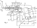
- Fig. 1 shows as an example of a hand-held machine tool schematically a hammer drill 1.
- the hammer drill 1 has a tool holder 2, in which a drill 3 or other tool can be used and locked.
- the exemplary hammer drill 1 has a rotary drive 4, which rotatably drives the tool holder 2 about its working axis 5 .
- the rotary drive 4 is based on an electric motor 6, which the user can turn on and off.
- the exemplary rotary drive 4 is rigidly coupled to the tool holder 2 .
- the exemplary rotary drive 4 includes a (motor) shaft 7, a reducing gear 8, a slip clutch 9 and an output shaft 10.
- a striking mechanism 11 strikes periodically in a direction of impact 12 along the working axis 5 on the drill 3.
- the hammer mechanism 11 is preferably of the same electric motor 6 driven.
- a power supply is provided by a battery 13.
- the hammer drill 1 has a handle 14, which is typically fastened to an end of a machine housing 15 of the hammer drill 1 facing away from the tool holder 2 .
- An additional handle 16 can be fastened, for example, near the tool holder 2 .
- the electric motor 6 is connected via a main circuit 17 to the battery 13 .
- the power supply to the electric motor 6 is adjusted by a motor controller 18 .
- the engine controller 18 may adjust a rotational speed of the electric motor 6 by limiting the current flow in the main circuit 17 . Further, the motor controller 18 in a brushless electric motor 6 phase feed the current into respective coils of the electric motor 6 .
- the motor controller 18 includes, for example, a bridge circuit.
- the hammer drill 1 has a main switch 19 and an operating button 20.
- the main switch 19 is used for a general commissioning of the hammer drill 1.
- the operating button 20th allows the user during use, the electric motor 6 on and off and possibly specify a speed of the electric motor 6 .
- the main switch 19 is disposed on the engine case 15 .
- the main switch 19 has two switch positions: switched off and ready for use.
- the main switch 19 may be realized, for example, as a toggle switch.
- the mechanical main switch 19 engages mechanically in the two switching positions.
- the main switch 19 may be implemented electromechanically.
- the main switch 19 includes a mechanical button and a bistable circuit, eg a bistable relay. When the button is pressed, the bistable circuit changes from the switched-off switching position to the ready-to-use switching position or from the ready-to-use switching position to the switched-off switching position.
- the main switch 19 is arranged in the main circuit 17 of the hammer drill 1 .
- the main switch 19 interrupts the main circuit 17 in the switched-off position and closes the main circuit 17 in the operative switching position.
- the interruption of the main circuit 17 also preferably disconnects the motor controller 18 from the power supply.
- the hammer drill 1 behaves essentially as if the battery 13 were removed.
- the operating button 20 is arranged on the handle 16 , so that the handle 16 enclosing hand at the same time operates the operating button 20 .
- a shift lever 21 of the operation button 20 is preferably about as long as the handle 16, for example, a length of the shift lever corresponds to more than 60% of the length of the handle 16. The user can grip the shift lever 21 with multiple fingers.
- the operating button 20 is expediently arranged on a surface of the handle 16 which points in the striking direction 12 .
- the operation button 20 has a single stable home position.
- a return spring 22 is compressed at a deflection of the operating button 20 from the basic position and accordingly exerts a restoring force in the direction of the basic position on the operating button 20 and its shift lever 21 .
- the operating button 20 can be pressed different degrees or moved far different from the basic position.
- the operating button 20 detects the pressing force or the deflection and generates a signal dependent on the pressing force or deflection.
- the signal can be generated for example by means of a potentiometer.
- the operating button 20 communicates with the motor controller 18.
- the signal of the operating button 20 is evaluated by the motor controller 18 . If a signal corresponding to the basic position is present, the motor controller 18 sets the speed of the electric motor 6 to zero.
- the hammer drill 1 is inactive. Otherwise, the engine controller 18 controls a rotational speed of the electric motor 6 in response to an encoded in the signal pressing force or deflection. The speed can be increased continuously or stepwise with increasing contact pressure or deflection.
- the hammer drill 1 is active.
- the operating button 20 is substantially free of power.
- the main circuit 17 does not run through the operating button 20.
- a current through the operating button 20 is clear, by several orders of magnitude, less than the current which is supplied to the electric motor 6 via the main circuit 17 .
- the main switch 19 may be provided with a timer 24 .
- the timer 24 determines the duration of an inactive phase of the hammer drill 1. For example, the timer 24 starts a time detection as soon as the operation button 20 returns to the home position, ie the user has released the operation button 20 to turn off the electric motor 6 . If the duration of the inactive phase exceeds a threshold value of, for example, five minutes or 30 minutes, the main switch 19 automatically switches to the switched-off position. The hammer drill 1 is now no longer ready for operation, a sole pressing of the operating button 20 does not start the electric motor 6. The user must press the main switch 19 again.
- the Schlagwerk 11 is a pneumatic impact mechanism.
- An excitation piston 25 is forced by the electric motor 6 in a periodic back and forth movement along the working axis 5 .
- a running on the working axis 5 racquet 26 is coupled via an air spring to the exciter piston 25 .
- the air spring is formed by a closed by the exciter piston 25 and the racket 26 pneumatic chamber 27 .
- the excitation piston 25 and the racket 26 may be guided in a stationary guide tube 28 , which at the same time terminates the pneumatic chamber 27 in the radial direction.
- the excitation piston is cup-shaped with a cylindrical cavity. The racket is guided in the cylindrical cavity.
- the pneumatic chamber 27 is in turn closed by the racket 26 and the excitation piston 25 along the working axis 5 , wherein the excitation piston 25 at the same time closes off the pneumatic chamber 27 in the radial direction.
- the racket is cup-shaped and guided the exciter piston in the cylindrical cavity of the racket.
- the striking mechanism 11 preferably has an anvil 29, which transmits a stroke of the racket 26 to the drill bit 3 .
- the striker 29 is located on the working axis 5 between the racket 26 and the tool holder 2.
- the striker 29 is movable on the working axis 5 guided.
- the drill 3 is in operation on the striker 29 , so that when the racket 26 strikes the opposite end of the striker 29 , a shock wave is introduced through the striker 29 in the drill 3 .
- the percussion mechanism 11 has a blanking shutdown based on one or more vents 30 through which the pneumatic chamber 27 can be vented.
- the ventilation openings 30 are normally closed by the racket 26 or indirectly by the striker 29 .
- the ventilation openings 30 are only opened when, due to a lack of contact pressure, the striker 29 and the striker 26 are displaced in the direction of impact 12 beyond an impact position.
- the impact position is defined by a rear stop, on which the striker 29 can rest against the direction of impact 12 .
- the drill 3 slides against the direction of impact 12 in the tool holder 2 and pushes the striker 29 to the stop, ergo in the strike position.
- the racket 26 is in the impact position when the racket 26 abuts the striker in the strike position 29 .
Landscapes
- Engineering & Computer Science (AREA)
- Mechanical Engineering (AREA)
- Percussive Tools And Related Accessories (AREA)
Abstract
Die Handwerkzeugmaschine (1) hat ein Maschinengehäuse (15) und einen Handgriff (16) zum Halten und Führen der Handwerkzeugmaschine (1). Ein pneumatisches Schlagwerk (11) wird von einem Elektromotor (6) angetrieben. Eine Batterie (13) versorgt den Elektromotor (6) mit elektrischem Strom. Ein Hauptschalter (19) ist in einen Hauptstromkreis (17) zwischen die Batterie (13) und eine Motorsteuerung (18) geschaltet, um eine Stromversorgung der Motorsteuerung (18) in einer ausgeschalteten Stellung des Hauptschalters (19) zu unterbrechen. Ein Betriebstaster (20) kommuniziert mit der Motorsteuerung (18), wobei die Motorsteuerung (18) eine Drehzahl des Elektromotors (6) ansprechend auf die Betätigung des Betriebstasters (20) einstellt. Der Hauptschalter (19) kann für den Transport die Handwerkzeugmaschine (1) unabhängig von dem Betriebstaster (20) abschalten.
Description
- Die vorliegende Erfindung betrifft eine meißelnde Handwerkzeugmaschine mit einem Schlagwerk.
- Batteriegetriebene meißelnde Handwerkzeugmaschinen wie in der
DE8501912U1 haben einen Betriebstaster, um die Handwerkzeugmaschine ein- und auszuschalten. Der Betriebstaster ist an dem Handgriff angeordnet, wodurch die Handwerkzeugmaschine durch die führende Hand ergonomisch in Betrieb genommen werden kann. Der Anwender nutzt den Handgriff auch für den Transport der Handwerkzeugmaschine. Hierbei kann der Anwender versehentlich den Betriebstaster betätigen. Meißelnde Handwerkzeugmaschinen können eine Leerschlagabschaltung aufweisen, welche bei fehlendem Anpressdruck trotz laufendem Elektromotor das pneumatische Schlagwerk mittels eines Ventils deaktivieren. Bei langen und zumeist auch schweren Werkzeugen kann dieses während des Tragens an dem Boden schleifen. Hält der Anwender in diesem Fall den Handgriff und den Betriebstaster unglücklich fest umschlossen, könnte der Anpressdruck ausreichen, das pneumatische Schlagwerk zu aktivieren. - Erfindungsgemäß hat eine Handwerkzeugmaschine ein Maschinengehäuse und einen Handgriff zum Halten und Führen der Handwerkzeugmaschine. Ein pneumatisches Schlagwerk wird von einem Elektromotor angetrieben. Eine Batterie versorgt den Elektromotor mit elektrischem Strom. Ein Hauptschalter ist in einen Hauptstromkreis zwischen die Batterie und die Motorsteuerung geschaltet, um eine Stromversorgung der Motorsteuerung in einer ausgeschalteten Stellung des Hauptschalters zu unterbrechen. Ein Betriebstaster kommuniziert mit der Motorsteuerung, wobei die Motorsteuerung eine Drehzahl des Elektromotors ansprechend auf die Betätigung des Betriebstasters einstellt. Der Hauptschalter kann für den Transport die Handwerkzeugmaschine unabhängig von dem Betriebstaster abschalten.
- Die nachfolgende Beschreibung erläutert die Erfindung anhand von exemplarischen Ausführungsformen und Figuren. In den Figuren zeigen:
-
Fig. 1 einen Bohrhammer - Gleiche oder funktionsgleiche Elemente werden durch gleiche Bezugszeichen in den Figuren indiziert, soweit nicht anders angegeben.
-
Fig. 1 zeigt als Beispiel einer handgeführten Werkzeugmaschine schematisch einen Bohrhammer 1. Der Bohrhammer 1 hat einen Werkzeughalter 2, in welchen ein Bohrer 3 oder anderes Werkzeug eingesetzt und verriegelt werden kann. Der beispielhafte Bohrhammer 1 hat einen Drehantrieb 4, welcher den Werkzeughalter 2 um dessen Arbeitsachse 5 drehend antreibt. Der Drehantrieb 4 basiert auf einem Elektromotor 6, den der Anwender ein- und ausschalten kann. Der beispielhafte Drehantrieb 4 ist starr mit dem Werkzeughalter 2 gekoppelt. Der beispielhafte Drehantrieb 4 beinhaltet eine (Motor-) Welle 7, ein untersetzendes Getriebe 8, eine Rutschkupplung 9 und eine Abtriebswelle 10. Ein Schlagwerk 11 schlägt periodisch in einer Schlagrichtung 12 längs der Arbeitsachse 5 auf den Bohrer 3. Das Schlagwerk 11 wird vorzugsweise von dem gleichen Elektromotor 6 angetrieben. Eine Energieversorgung erfolgt durch eine Batterie 13. Der Bohrhammer 1 hat einen Handgriff 14, der typischerweise an einem dem Werkzeughalter 2 abgewandten Ende eines Maschinengehäuses 15 des Bohrhammers 1 befestigt ist. Ein zusätzlicher Handgriff 16 kann beispielsweise nahe des Werkzeughalters 2 befestigt werden. - Der Elektromotor 6 ist über einen Hauptstromkreis 17 mit der Batterie 13 verbunden. Die Stromzufuhr zu dem Elektromotor 6 wird durch eine Motorsteuerung 18 eingestellt. Die Motorsteuerung 18 kann eine Drehzahl des Elektromotors 6 durch Begrenzen des Stromflusses in dem Hauptstromkreis 17 einstellen. Ferner kann die Motorsteuerung 18 bei einem bürstenlosen Elektromotor 6 den Strom phasengesteuert in jeweilige Spulen des Elektromotors 6 einspeisen. Die Motorsteuerung 18 beinhaltet dazu beispielsweise eine Brückenschaltung.
- Der Bohrhammer 1 hat einen Hauptschalter 19 und einen Betriebstaster 20. Der Hauptschalter 19 dient einer generellen Inbetriebnahme des Bohrhammers 1. Der Betriebstaster 20 ermöglicht dem Anwender während der Verwendung den Elektromotor 6 ein- und auszuschalten und ggf. eine Drehzahl des Elektromotor 6 vorzugeben.
- Der Hauptschalter 19 ist an dem Maschinengehäuse 15 angeordnet. Der Hauptschalter 19 hat zwei Schaltstellungen: ausgeschaltet und betriebsbereit. Der Hauptschalter 19 kann beispielsweise als Kippschalter realisiert sein. Der mechanische Hauptschalter 19 rastet mechanisch in den beiden Schaltstellungen ein. Alternativ kann der Hauptschalter 19 elektromechanisch realisiert sein. Der Hauptschalter 19 enthält einen mechanischen Taster und eine bistabile Schaltung, z.B. ein bistabiles Relais. Mit Betätigen des Tasters wechselt die bistabile Schaltung von der ausgeschaltenen Schaltstellung in die betriebsbereite Schaltstellung bzw. von der betriebsbereiten Schaltstellung in die ausgeschaltene Schaltstellung. Der Hauptschalter 19 ist in dem Hauptstromkreis 17 des Bohrhammers 1 angeordnet. Der Hauptschalter 19 unterbricht den Hauptstromkreis 17 in der ausgeschalteten Schaltstellung und schließt den Hauptstromkreis 17 in der betriebsbereiten Schaltstellung. Das Unterbrechen des Hauptstromkreises 17 trennt auch vorzugsweise die Motorsteuerung 18 von der Stromversorgung. Der Bohrhammer 1 verhält sich im Wesentlichen, als wenn die Batterie 13 entfernt wäre.
- Der Betriebstaster 20 ist an dem Handgriff 16 angeordnet, so dass die den Handgriff 16 umschließende Hand zugleich den Betriebstaster 20 betätigt. Ein Schalthebel 21 des Betriebstasters 20 ist vorzugsweise etwa so lange wie der Handgriff 16, z.B. eine Länge des Schalthebels entspricht mehr als 60 % der Länge des Handgriffs 16. Der Anwender kann den Schalthebel 21 mit mehreren Fingern greifen. Zweckmäßigerweise ist der Betriebstaster 20 an einer in Schlagrichtung 12 weisenden Fläche des Handgriffs 16 angeordnet. Der Betriebstaster 20 hat eine einzige stabile Grundstellung. Eine Rückstellfeder 22 wird bei einer Auslenkung des Betriebstasters 20 aus der Grundstellung komprimiert und übt entsprechend eine Rückstellkraft in Richtung zu der Grundstellung auf den Betriebstaster 20 bzw. dessen Schalthebel 21 aus. Der Betriebstaster 20 kann verschieden stark angedrückt oder verschieden weit gegenüber der Grundstellung verschoben werden. Der Betriebstaster 20 erfasst die Anpresskraft oder die Auslenkung und erzeugt ein von der Anpresskraft bzw. Auslenkung abhängiges Signal. Das Signal kann beispielsweise mittels eines Potentiometers erzeugt werden.
- Falls die Hauptschalter 19 betriebsbereit geschaltet ist, kommuniziert der Betriebstaster 20 mit der Motorsteuerung 18. Das Signal des Betriebstasters 20 wird von der Motorsteuerung 18 auswertet. Sofern ein der Grundstellung entsprechendes Signal anliegt, setzt die Motorsteuerung 18 die Drehzahl des Elektromotors 6 auf Null. Der Bohrhammer 1 ist inaktiv. Andernfalls steuert die Motorsteuerung 18 eine Drehzahl des Elektromotors 6 ansprechend auf eine in dem Signal kodierte Anpresskraft bzw. Auslenkung. Die Drehzahl kann kontinuierlich oder stufenweise mit zunehmender Anpresskraft bzw. Auslenkung erhöht werden. Der Bohrhammer 1 ist aktiv.
- Der Betriebstaster 20 ist im Wesentlichen stromfrei. Der Hauptstromkreis 17 läuft nicht durch den Betriebstaster 20. Ein Strom durch den Betriebstaster 20 ist deutlich, um mehrere Größenordnungen, geringer als der Strom welcher über den Hauptstromkreis 17 dem Elektromotor 6 zugeführt wird.
- Der Hauptschalter 19 kann mit einer Zeitsteuerung 24 versehen sein. Die Zeitsteuerung 24 ermittelt die Dauer einer inaktiven Phase des Bohrhammers 1. Beispielsweise beginnt die Zeitsteuerung 24 eine Zeiterfassung sobald der Betriebstaster 20 in die Grundstellung zurückkehrt, d.h. der Anwender den Betriebstaster 20 losgelassen hat, um den Elektromotor 6 abzuschalten. Überschreitet die Dauer der inaktiven Phase einen Schwellwert, von z.B. fünf Minuten oder 30 Minuten, wechselt der Hauptschalter 19 selbsttätig in die ausgeschaltete Stellung. Der Bohrhammer 1 ist nun nicht mehr betriebsbereit, ein alleiniges Andrücken des Betriebstasters 20 startet nicht den Elektromotor 6. Der Anwender muss erneut den Hauptschalter 19 betätigen.
- Das Schlagwerk 11 ist ein pneumatisches Schlagwerk. Ein Erregerkolben 25 wird durch den Elektromotor 6 in eine periodische Vor- und Zurückbewegung längs der Arbeitsachse 5 gezwungen. Ein auf der Arbeitsachse 5 laufender Schläger 26 ist über eine Luftfeder an den Erregerkolben 25 angekoppelt. Die Luftfeder ist durch eine von dem Erregerkolben 25 und dem Schläger 26 abgeschlossene pneumatische Kammer 27 gebildet. Der Erregerkolben 25 und der Schläger 26 können in einem stehenden Führungsrohr 28 geführt sein, welches zugleich die pneumatische Kammer 27 in radialer Richtung abschließt. Bei alternativen Ausführungen ist der Erregerkolben topfförmig mit einem zylindrischen Hohlraum ausgebildet. Der Schläger ist in dem zylindrischen Hohlraum geführt. Die pneumatische Kammer 27 ist wiederum durch den Schläger 26 und den Erregerkolben 25 längs der Arbeitsachse 5 geschlossen, wobei der Erregerkolben 25 zugleich die pneumatischen Kammer 27 in radialer Richtung abschließt. In einer weiteren Ausführung ist der Schläger topfförmig ausgebildet und der Erregerkolben in dem zylindrischen Hohlraum des Schlägers geführt.
- Das Schlagwerk 11 hat vorzugsweise einen Döpper 29, welcher einen Schlag des Schlägers 26 auf den Bohrer 3 überträgt. Der Döpper 29 liegt auf der Arbeitsachse 5 zwischen dem Schläger 26 und dem Werkzeughalter 2. Der Döpper 29 ist auf der Arbeitsachse 5 beweglich geführt. Der Bohrer 3 liegt im Betrieb an dem Döpper 29 an, so dass wenn der Schläger 26 auf das gegenüberliegende Ende des Döppers 29 aufschlägt, eine Stoßwelle durch den Döpper 29 in den Bohrer 3 eingeleitet wird.
- Das Schlagwerk 11 hat eine Leerschlagabschaltung basierend auf ein oder mehreren Belüftungsöffnungen 30, über welche die pneumatische Kammer 27 belüftet werden kann. Die Belüftungsöffnungen 30 sind im Regelfall durch den Schläger 26 oder mittelbar durch den Döpper 29 verschlossen. Die Belüftungsöffnungen 30 werden nur geöffnet, wenn aufgrund fehlendem Anpressdrucks der Döpper 29 und der Schläger 26 in Schlagrichtung 12 über eine Schlagstellung hinaus verschoben sind. Die Schlagstellung ist durch einen rückwärtigen Anschlag definiert, an dem der Döpper 29 entgegen der Schlagrichtung 12 anliegen kann. Wenn der Anwender den Bohrer 3 an den Untergrund anpresst, gleitet der Bohrer 3 entgegen der Schlagrichtung 12 in den Werkzeughalter 2 und schiebt dabei den Döpper 29 an den Anschlag, ergo in die Schlagstellung. Der Schläger 26 ist in der Schlagstellung, wenn der Schläger 26 an dem in der Schlagstellung befindlichen Döpper 29 anliegt.
Claims (4)
- Handwerkzeugmaschine (1) mit
einem Maschinengehäuse (15), einem an dem Maschinengehäuse (15) befestigten Handgriff (16) zum Halten und Führen der Handwerkzeugmaschine (1) während eines Betriebs, einem pneumatischen Schlagwerk (11) mit einer Leerschlagabschaltung, einem Elektromotor (6) zum Antreiben des pneumatischen Schlagwerks (11), einer Batterie (13) zum Versorgen einer des Elektromotors (6) mit elektrischem Strom,
einem Hauptschalter (19), der in einen Hauptstromkreis zwischen die Batterie (13) und die Motorsteuerung (18) zum Unterbrechen einer Stromversorgung der Motorsteuerung (18) geschaltet ist, und
einem an dem Handgriff (16) angeordneten Betriebstaster (20), der mit der Motorsteuerung (18) kommunizierend verbunden ist, wobei die Motorsteuerung (18) eine Drehzahl des Elektromotors (6) ansprechend auf die Betätigung des Betriebstasters (20) einstellt. - Handwerkzeugmaschine (1) nach Anspruch 1, dadurch kennzeichnet, dass der Hauptschalter (19) eine Zeitsteuerung (24) beinhaltet, welche den Hauptschalter (19) in eine ausgeschaltete Stellung schaltet, wenn der Betriebstaster (20) für eine vorgegebene Zeitspanne unbetätigt ist.
- Handwerkzeugmaschine (1) nach Anspruch 1 oder 2, dadurch kennzeichnet, dass der Hauptschalter (19) entfernt von dem Handgriff (16) angeordnet ist.
- Handwerkzeugmaschine (1) nach einem der vorhergehenden Ansprüche, dadurch kennzeichnet, dass eine Länge eines Schalthebels (21) des Betriebstasters (20) größer als 60% einer Länge des Handgriffs (16) ist.
Priority Applications (1)
| Application Number | Priority Date | Filing Date | Title |
|---|---|---|---|
| EP17181210.0A EP3427899A1 (de) | 2017-07-13 | 2017-07-13 | Handwerkzeugmaschine |
Applications Claiming Priority (1)
| Application Number | Priority Date | Filing Date | Title |
|---|---|---|---|
| EP17181210.0A EP3427899A1 (de) | 2017-07-13 | 2017-07-13 | Handwerkzeugmaschine |
Publications (1)
| Publication Number | Publication Date |
|---|---|
| EP3427899A1 true EP3427899A1 (de) | 2019-01-16 |
Family
ID=59337561
Family Applications (1)
| Application Number | Title | Priority Date | Filing Date |
|---|---|---|---|
| EP17181210.0A Withdrawn EP3427899A1 (de) | 2017-07-13 | 2017-07-13 | Handwerkzeugmaschine |
Country Status (1)
| Country | Link |
|---|---|
| EP (1) | EP3427899A1 (de) |
Cited By (2)
| Publication number | Priority date | Publication date | Assignee | Title |
|---|---|---|---|---|
| EP4005738A1 (de) * | 2020-11-27 | 2022-06-01 | Hilti Aktiengesellschaft | Handwerkzeugmaschine |
| US11872683B2 (en) | 2021-06-07 | 2024-01-16 | Black & Decker Inc. | Side handle for power tool |
Citations (9)
| Publication number | Priority date | Publication date | Assignee | Title |
|---|---|---|---|---|
| DE2343661A1 (de) * | 1973-08-30 | 1975-03-06 | Bosch Gmbh Robert | Bohrhammer |
| DE8501912U1 (de) | 1985-01-25 | 1986-05-15 | Robert Bosch Gmbh, 7000 Stuttgart | Elektropneumatischer Bohr- und/oder Schlaghammer mit batteriegespeistem Antriebsmotor |
| FR2625931A1 (fr) * | 1988-01-14 | 1989-07-21 | Peugeot Outillage Elect | Machine electrique a main pour percage et percussion |
| JPH01291686A (ja) * | 1988-05-14 | 1989-11-24 | Matsushita Electric Works Ltd | 電動工具 |
| DE102007035096A1 (de) * | 2007-07-26 | 2009-01-29 | Robert Bosch Gmbh | Gerätesicherungsvorrichtung |
| EP2153942A1 (de) * | 2007-06-05 | 2010-02-17 | Max Co., Ltd. | Hammerwerkzeug |
| US20110284255A1 (en) * | 2009-02-02 | 2011-11-24 | Takahiro Ookubo | Electric boring tool |
| US20150027742A1 (en) * | 2009-04-08 | 2015-01-29 | Husqvarna Ab | Battery-Powered Portable Tools |
| WO2017102431A1 (de) * | 2015-12-15 | 2017-06-22 | Hilti Aktiengesellschaft | Schlagende handwerkzeugmaschine |
-
2017
- 2017-07-13 EP EP17181210.0A patent/EP3427899A1/de not_active Withdrawn
Patent Citations (9)
| Publication number | Priority date | Publication date | Assignee | Title |
|---|---|---|---|---|
| DE2343661A1 (de) * | 1973-08-30 | 1975-03-06 | Bosch Gmbh Robert | Bohrhammer |
| DE8501912U1 (de) | 1985-01-25 | 1986-05-15 | Robert Bosch Gmbh, 7000 Stuttgart | Elektropneumatischer Bohr- und/oder Schlaghammer mit batteriegespeistem Antriebsmotor |
| FR2625931A1 (fr) * | 1988-01-14 | 1989-07-21 | Peugeot Outillage Elect | Machine electrique a main pour percage et percussion |
| JPH01291686A (ja) * | 1988-05-14 | 1989-11-24 | Matsushita Electric Works Ltd | 電動工具 |
| EP2153942A1 (de) * | 2007-06-05 | 2010-02-17 | Max Co., Ltd. | Hammerwerkzeug |
| DE102007035096A1 (de) * | 2007-07-26 | 2009-01-29 | Robert Bosch Gmbh | Gerätesicherungsvorrichtung |
| US20110284255A1 (en) * | 2009-02-02 | 2011-11-24 | Takahiro Ookubo | Electric boring tool |
| US20150027742A1 (en) * | 2009-04-08 | 2015-01-29 | Husqvarna Ab | Battery-Powered Portable Tools |
| WO2017102431A1 (de) * | 2015-12-15 | 2017-06-22 | Hilti Aktiengesellschaft | Schlagende handwerkzeugmaschine |
Cited By (4)
| Publication number | Priority date | Publication date | Assignee | Title |
|---|---|---|---|---|
| EP4005738A1 (de) * | 2020-11-27 | 2022-06-01 | Hilti Aktiengesellschaft | Handwerkzeugmaschine |
| WO2022111988A1 (de) * | 2020-11-27 | 2022-06-02 | Hilti Aktiengesellschaft | Handwerkzeugmaschine |
| US11872683B2 (en) | 2021-06-07 | 2024-01-16 | Black & Decker Inc. | Side handle for power tool |
| US11931879B2 (en) | 2021-06-07 | 2024-03-19 | Black & Decker Inc. | Power tool dual-trigger operation |
Similar Documents
| Publication | Publication Date | Title |
|---|---|---|
| DE4019895C2 (de) | Verfahren und Vorrichtung zur Steuerung des Betriebs von Elektrohandgeräten | |
| EP1466702B1 (de) | Steuerung einer Elektrohandwerkzeugmaschine | |
| EP0224010B1 (de) | Motorisch angetriebenes Handwerkzeug für bohrenden oder schlagbohrenden Betrieb | |
| DE102004012433A1 (de) | Handwerkzeugmaschine | |
| DE4344849A1 (de) | Werkzeugmaschine | |
| EP2127816A2 (de) | Handgeführtes elektrisch betriebenes Eintreibgerät | |
| EP3427899A1 (de) | Handwerkzeugmaschine | |
| EP2517839B1 (de) | Werkzeugmaschine und Steuerungsverfahren | |
| EP3554765B1 (de) | Steuerungsverfahren für eine schlagende handwerkzeugmaschine | |
| EP2212062B1 (de) | Handwerkzeugmaschine | |
| EP1632313B1 (de) | Schraubgerät mit axial wirkendem Schlagmechanismus | |
| EP4058246A1 (de) | Verfahren zum steuern und regeln einer werkzeugmaschine | |
| EP4058249A1 (de) | Verfahren zum steuern und regeln einer werkzeugmaschine | |
| EP2319661A1 (de) | Handwerkzeugmaschine | |
| WO2023006538A1 (de) | Verfahren zum steuern und regeln einer werkzeugmaschine | |
| EP4058247A1 (de) | Verfahren zum steuern und regeln einer werkzeugmaschine und handgriff für werkzeugmaschine | |
| WO2014056820A1 (de) | Verfahren und vorrichtung zum betreiben einer handwerkzeugmaschine mit einem tangentialschlagwerk | |
| EP4058248A1 (de) | Handgriffvorrichtung für eine werkzeugmaschine | |
| WO2016059017A1 (de) | MEIßELNDE HANDWERKZEUGMASCHINE | |
| DE810498C (de) | Elektrohammer | |
| EP3581337A1 (de) | Handwerkzeugmaschine | |
| EP4058250A1 (de) | Verfahren zum steuern und regeln einer werkzeugmaschine | |
| EP3593951A1 (de) | Handwerkzeugmaschine |
Legal Events
| Date | Code | Title | Description |
|---|---|---|---|
| PUAI | Public reference made under article 153(3) epc to a published international application that has entered the european phase |
Free format text: ORIGINAL CODE: 0009012 |
|
| AK | Designated contracting states |
Kind code of ref document: A1 Designated state(s): AL AT BE BG CH CY CZ DE DK EE ES FI FR GB GR HR HU IE IS IT LI LT LU LV MC MK MT NL NO PL PT RO RS SE SI SK SM TR |
|
| AX | Request for extension of the european patent |
Extension state: BA ME |
|
| STAA | Information on the status of an ep patent application or granted ep patent |
Free format text: STATUS: THE APPLICATION IS DEEMED TO BE WITHDRAWN |
|
| 18D | Application deemed to be withdrawn |
Effective date: 20190717 |