EP3427899A1 - Machine-outil portative - Google Patents
Machine-outil portative Download PDFInfo
- Publication number
- EP3427899A1 EP3427899A1 EP17181210.0A EP17181210A EP3427899A1 EP 3427899 A1 EP3427899 A1 EP 3427899A1 EP 17181210 A EP17181210 A EP 17181210A EP 3427899 A1 EP3427899 A1 EP 3427899A1
- Authority
- EP
- European Patent Office
- Prior art keywords
- operating button
- main switch
- electric motor
- handle
- hand tool
- Prior art date
- Legal status (The legal status is an assumption and is not a legal conclusion. Google has not performed a legal analysis and makes no representation as to the accuracy of the status listed.)
- Withdrawn
Links
Images
Classifications
-
- B—PERFORMING OPERATIONS; TRANSPORTING
- B25—HAND TOOLS; PORTABLE POWER-DRIVEN TOOLS; MANIPULATORS
- B25D—PERCUSSIVE TOOLS
- B25D17/00—Details of, or accessories for, portable power-driven percussive tools
-
- B—PERFORMING OPERATIONS; TRANSPORTING
- B25—HAND TOOLS; PORTABLE POWER-DRIVEN TOOLS; MANIPULATORS
- B25F—COMBINATION OR MULTI-PURPOSE TOOLS NOT OTHERWISE PROVIDED FOR; DETAILS OR COMPONENTS OF PORTABLE POWER-DRIVEN TOOLS NOT PARTICULARLY RELATED TO THE OPERATIONS PERFORMED AND NOT OTHERWISE PROVIDED FOR
- B25F5/00—Details or components of portable power-driven tools not particularly related to the operations performed and not otherwise provided for
-
- B—PERFORMING OPERATIONS; TRANSPORTING
- B25—HAND TOOLS; PORTABLE POWER-DRIVEN TOOLS; MANIPULATORS
- B25D—PERCUSSIVE TOOLS
- B25D2211/00—Details of portable percussive tools with electromotor or other motor drive
- B25D2211/003—Crossed drill and motor spindles
-
- B—PERFORMING OPERATIONS; TRANSPORTING
- B25—HAND TOOLS; PORTABLE POWER-DRIVEN TOOLS; MANIPULATORS
- B25D—PERCUSSIVE TOOLS
- B25D2211/00—Details of portable percussive tools with electromotor or other motor drive
- B25D2211/06—Means for driving the impulse member
- B25D2211/068—Crank-actuated impulse-driving mechanisms
-
- B—PERFORMING OPERATIONS; TRANSPORTING
- B25—HAND TOOLS; PORTABLE POWER-DRIVEN TOOLS; MANIPULATORS
- B25D—PERCUSSIVE TOOLS
- B25D2250/00—General details of portable percussive tools; Components used in portable percussive tools
- B25D2250/035—Bleeding holes, e.g. in piston guide-sleeves
-
- B—PERFORMING OPERATIONS; TRANSPORTING
- B25—HAND TOOLS; PORTABLE POWER-DRIVEN TOOLS; MANIPULATORS
- B25D—PERCUSSIVE TOOLS
- B25D2250/00—General details of portable percussive tools; Components used in portable percussive tools
- B25D2250/131—Idling mode of tools
-
- B—PERFORMING OPERATIONS; TRANSPORTING
- B25—HAND TOOLS; PORTABLE POWER-DRIVEN TOOLS; MANIPULATORS
- B25D—PERCUSSIVE TOOLS
- B25D2250/00—General details of portable percussive tools; Components used in portable percussive tools
- B25D2250/195—Regulation means
- B25D2250/201—Regulation means for speed, e.g. drilling or percussion speed
-
- B—PERFORMING OPERATIONS; TRANSPORTING
- B25—HAND TOOLS; PORTABLE POWER-DRIVEN TOOLS; MANIPULATORS
- B25D—PERCUSSIVE TOOLS
- B25D2250/00—General details of portable percussive tools; Components used in portable percussive tools
- B25D2250/221—Sensors
-
- B—PERFORMING OPERATIONS; TRANSPORTING
- B25—HAND TOOLS; PORTABLE POWER-DRIVEN TOOLS; MANIPULATORS
- B25D—PERCUSSIVE TOOLS
- B25D2250/00—General details of portable percussive tools; Components used in portable percussive tools
- B25D2250/255—Switches
-
- B—PERFORMING OPERATIONS; TRANSPORTING
- B25—HAND TOOLS; PORTABLE POWER-DRIVEN TOOLS; MANIPULATORS
- B25D—PERCUSSIVE TOOLS
- B25D2250/00—General details of portable percussive tools; Components used in portable percussive tools
- B25D2250/255—Switches
- B25D2250/265—Trigger mechanism in handle
-
- B—PERFORMING OPERATIONS; TRANSPORTING
- B25—HAND TOOLS; PORTABLE POWER-DRIVEN TOOLS; MANIPULATORS
- B25D—PERCUSSIVE TOOLS
- B25D2250/00—General details of portable percussive tools; Components used in portable percussive tools
- B25D2250/275—Tools having at least two similar components
Definitions
- the present invention relates to a chiseling hand tool with a striking mechanism.
- Battery - powered chiseling hand tool machines as in the DE8501912U1 have an operating button to turn the hand tool on and off.
- the operating button is arranged on the handle, whereby the hand tool can be ergonomically put into operation by the leading hand.
- the user also uses the handle for transporting the hand tool. In this case, the user can inadvertently operate the operation button.
- Chiseling hand tool machines may have a Leerschlagabscnies, which deactivate the pneumatic impact mechanism by means of a valve in the absence of contact pressure despite running electric motor. For long and mostly heavy tools this can drag while carrying on the ground. In this case, if the user unhappily holds the handle and the operating button tightly, the contact pressure could be sufficient to activate the pneumatic impact mechanism.
- a handheld power tool has a machine housing and a handle for holding and guiding the handheld power tool.
- a pneumatic impact mechanism is driven by an electric motor.
- a battery supplies the electric motor with electric current.
- a main switch is connected in a main circuit between the battery and the motor controller to interrupt a power supply of the motor controller in an off position of the main switch.
- An operating button communicates with the engine controller, the engine controller adjusting a speed of the electric motor in response to the operation of the operating button. The main switch can switch off the hand tool for transport regardless of the operating button.
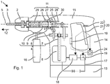
- Fig. 1 shows as an example of a hand-held machine tool schematically a hammer drill 1.
- the hammer drill 1 has a tool holder 2, in which a drill 3 or other tool can be used and locked.
- the exemplary hammer drill 1 has a rotary drive 4, which rotatably drives the tool holder 2 about its working axis 5 .
- the rotary drive 4 is based on an electric motor 6, which the user can turn on and off.
- the exemplary rotary drive 4 is rigidly coupled to the tool holder 2 .
- the exemplary rotary drive 4 includes a (motor) shaft 7, a reducing gear 8, a slip clutch 9 and an output shaft 10.
- a striking mechanism 11 strikes periodically in a direction of impact 12 along the working axis 5 on the drill 3.
- the hammer mechanism 11 is preferably of the same electric motor 6 driven.
- a power supply is provided by a battery 13.
- the hammer drill 1 has a handle 14, which is typically fastened to an end of a machine housing 15 of the hammer drill 1 facing away from the tool holder 2 .
- An additional handle 16 can be fastened, for example, near the tool holder 2 .
- the electric motor 6 is connected via a main circuit 17 to the battery 13 .
- the power supply to the electric motor 6 is adjusted by a motor controller 18 .
- the engine controller 18 may adjust a rotational speed of the electric motor 6 by limiting the current flow in the main circuit 17 . Further, the motor controller 18 in a brushless electric motor 6 phase feed the current into respective coils of the electric motor 6 .
- the motor controller 18 includes, for example, a bridge circuit.
- the hammer drill 1 has a main switch 19 and an operating button 20.
- the main switch 19 is used for a general commissioning of the hammer drill 1.
- the operating button 20th allows the user during use, the electric motor 6 on and off and possibly specify a speed of the electric motor 6 .
- the main switch 19 is disposed on the engine case 15 .
- the main switch 19 has two switch positions: switched off and ready for use.
- the main switch 19 may be realized, for example, as a toggle switch.
- the mechanical main switch 19 engages mechanically in the two switching positions.
- the main switch 19 may be implemented electromechanically.
- the main switch 19 includes a mechanical button and a bistable circuit, eg a bistable relay. When the button is pressed, the bistable circuit changes from the switched-off switching position to the ready-to-use switching position or from the ready-to-use switching position to the switched-off switching position.
- the main switch 19 is arranged in the main circuit 17 of the hammer drill 1 .
- the main switch 19 interrupts the main circuit 17 in the switched-off position and closes the main circuit 17 in the operative switching position.
- the interruption of the main circuit 17 also preferably disconnects the motor controller 18 from the power supply.
- the hammer drill 1 behaves essentially as if the battery 13 were removed.
- the operating button 20 is arranged on the handle 16 , so that the handle 16 enclosing hand at the same time operates the operating button 20 .
- a shift lever 21 of the operation button 20 is preferably about as long as the handle 16, for example, a length of the shift lever corresponds to more than 60% of the length of the handle 16. The user can grip the shift lever 21 with multiple fingers.
- the operating button 20 is expediently arranged on a surface of the handle 16 which points in the striking direction 12 .
- the operation button 20 has a single stable home position.
- a return spring 22 is compressed at a deflection of the operating button 20 from the basic position and accordingly exerts a restoring force in the direction of the basic position on the operating button 20 and its shift lever 21 .
- the operating button 20 can be pressed different degrees or moved far different from the basic position.
- the operating button 20 detects the pressing force or the deflection and generates a signal dependent on the pressing force or deflection.
- the signal can be generated for example by means of a potentiometer.
- the operating button 20 communicates with the motor controller 18.
- the signal of the operating button 20 is evaluated by the motor controller 18 . If a signal corresponding to the basic position is present, the motor controller 18 sets the speed of the electric motor 6 to zero.
- the hammer drill 1 is inactive. Otherwise, the engine controller 18 controls a rotational speed of the electric motor 6 in response to an encoded in the signal pressing force or deflection. The speed can be increased continuously or stepwise with increasing contact pressure or deflection.
- the hammer drill 1 is active.
- the operating button 20 is substantially free of power.
- the main circuit 17 does not run through the operating button 20.
- a current through the operating button 20 is clear, by several orders of magnitude, less than the current which is supplied to the electric motor 6 via the main circuit 17 .
- the main switch 19 may be provided with a timer 24 .
- the timer 24 determines the duration of an inactive phase of the hammer drill 1. For example, the timer 24 starts a time detection as soon as the operation button 20 returns to the home position, ie the user has released the operation button 20 to turn off the electric motor 6 . If the duration of the inactive phase exceeds a threshold value of, for example, five minutes or 30 minutes, the main switch 19 automatically switches to the switched-off position. The hammer drill 1 is now no longer ready for operation, a sole pressing of the operating button 20 does not start the electric motor 6. The user must press the main switch 19 again.
- the Schlagwerk 11 is a pneumatic impact mechanism.
- An excitation piston 25 is forced by the electric motor 6 in a periodic back and forth movement along the working axis 5 .
- a running on the working axis 5 racquet 26 is coupled via an air spring to the exciter piston 25 .
- the air spring is formed by a closed by the exciter piston 25 and the racket 26 pneumatic chamber 27 .
- the excitation piston 25 and the racket 26 may be guided in a stationary guide tube 28 , which at the same time terminates the pneumatic chamber 27 in the radial direction.
- the excitation piston is cup-shaped with a cylindrical cavity. The racket is guided in the cylindrical cavity.
- the pneumatic chamber 27 is in turn closed by the racket 26 and the excitation piston 25 along the working axis 5 , wherein the excitation piston 25 at the same time closes off the pneumatic chamber 27 in the radial direction.
- the racket is cup-shaped and guided the exciter piston in the cylindrical cavity of the racket.
- the striking mechanism 11 preferably has an anvil 29, which transmits a stroke of the racket 26 to the drill bit 3 .
- the striker 29 is located on the working axis 5 between the racket 26 and the tool holder 2.
- the striker 29 is movable on the working axis 5 guided.
- the drill 3 is in operation on the striker 29 , so that when the racket 26 strikes the opposite end of the striker 29 , a shock wave is introduced through the striker 29 in the drill 3 .
- the percussion mechanism 11 has a blanking shutdown based on one or more vents 30 through which the pneumatic chamber 27 can be vented.
- the ventilation openings 30 are normally closed by the racket 26 or indirectly by the striker 29 .
- the ventilation openings 30 are only opened when, due to a lack of contact pressure, the striker 29 and the striker 26 are displaced in the direction of impact 12 beyond an impact position.
- the impact position is defined by a rear stop, on which the striker 29 can rest against the direction of impact 12 .
- the drill 3 slides against the direction of impact 12 in the tool holder 2 and pushes the striker 29 to the stop, ergo in the strike position.
- the racket 26 is in the impact position when the racket 26 abuts the striker in the strike position 29 .
Landscapes
- Engineering & Computer Science (AREA)
- Mechanical Engineering (AREA)
- Percussive Tools And Related Accessories (AREA)
Priority Applications (1)
| Application Number | Priority Date | Filing Date | Title |
|---|---|---|---|
| EP17181210.0A EP3427899A1 (fr) | 2017-07-13 | 2017-07-13 | Machine-outil portative |
Applications Claiming Priority (1)
| Application Number | Priority Date | Filing Date | Title |
|---|---|---|---|
| EP17181210.0A EP3427899A1 (fr) | 2017-07-13 | 2017-07-13 | Machine-outil portative |
Publications (1)
| Publication Number | Publication Date |
|---|---|
| EP3427899A1 true EP3427899A1 (fr) | 2019-01-16 |
Family
ID=59337561
Family Applications (1)
| Application Number | Title | Priority Date | Filing Date |
|---|---|---|---|
| EP17181210.0A Withdrawn EP3427899A1 (fr) | 2017-07-13 | 2017-07-13 | Machine-outil portative |
Country Status (1)
| Country | Link |
|---|---|
| EP (1) | EP3427899A1 (fr) |
Cited By (2)
| Publication number | Priority date | Publication date | Assignee | Title |
|---|---|---|---|---|
| EP4005738A1 (fr) * | 2020-11-27 | 2022-06-01 | Hilti Aktiengesellschaft | Machine-outil portative |
| US11872683B2 (en) | 2021-06-07 | 2024-01-16 | Black & Decker Inc. | Side handle for power tool |
Citations (9)
| Publication number | Priority date | Publication date | Assignee | Title |
|---|---|---|---|---|
| DE2343661A1 (de) * | 1973-08-30 | 1975-03-06 | Bosch Gmbh Robert | Bohrhammer |
| DE8501912U1 (de) | 1985-01-25 | 1986-05-15 | Robert Bosch Gmbh, 7000 Stuttgart | Elektropneumatischer Bohr- und/oder Schlaghammer mit batteriegespeistem Antriebsmotor |
| FR2625931A1 (fr) * | 1988-01-14 | 1989-07-21 | Peugeot Outillage Elect | Machine electrique a main pour percage et percussion |
| JPH01291686A (ja) * | 1988-05-14 | 1989-11-24 | Matsushita Electric Works Ltd | 電動工具 |
| DE102007035096A1 (de) * | 2007-07-26 | 2009-01-29 | Robert Bosch Gmbh | Gerätesicherungsvorrichtung |
| EP2153942A1 (fr) * | 2007-06-05 | 2010-02-17 | Max Co., Ltd. | Outil de percussion |
| US20110284255A1 (en) * | 2009-02-02 | 2011-11-24 | Takahiro Ookubo | Electric boring tool |
| US20150027742A1 (en) * | 2009-04-08 | 2015-01-29 | Husqvarna Ab | Battery-Powered Portable Tools |
| WO2017102431A1 (fr) * | 2015-12-15 | 2017-06-22 | Hilti Aktiengesellschaft | Machine-outil portative à percussion |
-
2017
- 2017-07-13 EP EP17181210.0A patent/EP3427899A1/fr not_active Withdrawn
Patent Citations (9)
| Publication number | Priority date | Publication date | Assignee | Title |
|---|---|---|---|---|
| DE2343661A1 (de) * | 1973-08-30 | 1975-03-06 | Bosch Gmbh Robert | Bohrhammer |
| DE8501912U1 (de) | 1985-01-25 | 1986-05-15 | Robert Bosch Gmbh, 7000 Stuttgart | Elektropneumatischer Bohr- und/oder Schlaghammer mit batteriegespeistem Antriebsmotor |
| FR2625931A1 (fr) * | 1988-01-14 | 1989-07-21 | Peugeot Outillage Elect | Machine electrique a main pour percage et percussion |
| JPH01291686A (ja) * | 1988-05-14 | 1989-11-24 | Matsushita Electric Works Ltd | 電動工具 |
| EP2153942A1 (fr) * | 2007-06-05 | 2010-02-17 | Max Co., Ltd. | Outil de percussion |
| DE102007035096A1 (de) * | 2007-07-26 | 2009-01-29 | Robert Bosch Gmbh | Gerätesicherungsvorrichtung |
| US20110284255A1 (en) * | 2009-02-02 | 2011-11-24 | Takahiro Ookubo | Electric boring tool |
| US20150027742A1 (en) * | 2009-04-08 | 2015-01-29 | Husqvarna Ab | Battery-Powered Portable Tools |
| WO2017102431A1 (fr) * | 2015-12-15 | 2017-06-22 | Hilti Aktiengesellschaft | Machine-outil portative à percussion |
Cited By (4)
| Publication number | Priority date | Publication date | Assignee | Title |
|---|---|---|---|---|
| EP4005738A1 (fr) * | 2020-11-27 | 2022-06-01 | Hilti Aktiengesellschaft | Machine-outil portative |
| WO2022111988A1 (fr) * | 2020-11-27 | 2022-06-02 | Hilti Aktiengesellschaft | Outil électrique portatif |
| US11872683B2 (en) | 2021-06-07 | 2024-01-16 | Black & Decker Inc. | Side handle for power tool |
| US11931879B2 (en) | 2021-06-07 | 2024-03-19 | Black & Decker Inc. | Power tool dual-trigger operation |
Similar Documents
| Publication | Publication Date | Title |
|---|---|---|
| DE4019895C2 (de) | Verfahren und Vorrichtung zur Steuerung des Betriebs von Elektrohandgeräten | |
| EP1466702B1 (fr) | Contrôle d'un outil électrique | |
| EP0224010B1 (fr) | Outil portatif à moteur pour perçage avec ou sans percussion | |
| DE102004012433A1 (de) | Handwerkzeugmaschine | |
| DE4344849A1 (de) | Werkzeugmaschine | |
| EP2127816A2 (fr) | Dispositif d'enfoncement manuel entraîné de manière électrique | |
| EP3427899A1 (fr) | Machine-outil portative | |
| EP2517839B1 (fr) | Machine-outil et procédé de commande | |
| EP3554765B1 (fr) | Procédé de commande pour une machine-outil manuelle de frappe | |
| EP2212062B1 (fr) | Machine-outil à main | |
| EP1632313B1 (fr) | Outil de serrage avec mécanisme d'impact axial | |
| EP4058246A1 (fr) | Procédé permettant de commander et de régler une machine-outil | |
| EP4058249A1 (fr) | Procédé de commande et de réglage d'une machine-outil | |
| EP2319661A1 (fr) | Machine-outil portative | |
| WO2023006538A1 (fr) | Procédé de commande en boucle ouverte et en boucle fermée d'une machine-outil | |
| EP4058247A1 (fr) | Procédé de commande et de régulation d'une machine-outil et poignée pour machine-outil | |
| WO2014056820A1 (fr) | Procédé et dispositif permettant de faire fonctionner un outil électroportatif à mécanisme de percussion tangentielle | |
| EP4058248A1 (fr) | Dispositif de type poignée pour une machine-outil | |
| WO2016059017A1 (fr) | Machine-outil portative de burinage | |
| DE810498C (de) | Elektrohammer | |
| EP3581337A1 (fr) | Machine-outil portative | |
| EP4058250A1 (fr) | Procédé de commande et de régulation d'une machine-outil | |
| EP3593951A1 (fr) | Machine-outil portative |
Legal Events
| Date | Code | Title | Description |
|---|---|---|---|
| PUAI | Public reference made under article 153(3) epc to a published international application that has entered the european phase |
Free format text: ORIGINAL CODE: 0009012 |
|
| AK | Designated contracting states |
Kind code of ref document: A1 Designated state(s): AL AT BE BG CH CY CZ DE DK EE ES FI FR GB GR HR HU IE IS IT LI LT LU LV MC MK MT NL NO PL PT RO RS SE SI SK SM TR |
|
| AX | Request for extension of the european patent |
Extension state: BA ME |
|
| STAA | Information on the status of an ep patent application or granted ep patent |
Free format text: STATUS: THE APPLICATION IS DEEMED TO BE WITHDRAWN |
|
| 18D | Application deemed to be withdrawn |
Effective date: 20190717 |