EP2319661A1 - Machine-outil portative - Google Patents
Machine-outil portative Download PDFInfo
- Publication number
- EP2319661A1 EP2319661A1 EP10188569A EP10188569A EP2319661A1 EP 2319661 A1 EP2319661 A1 EP 2319661A1 EP 10188569 A EP10188569 A EP 10188569A EP 10188569 A EP10188569 A EP 10188569A EP 2319661 A1 EP2319661 A1 EP 2319661A1
- Authority
- EP
- European Patent Office
- Prior art keywords
- anvil
- tool
- side stop
- machine
- impact
- Prior art date
- Legal status (The legal status is an assumption and is not a legal conclusion. Google has not performed a legal analysis and makes no representation as to the accuracy of the status listed.)
- Withdrawn
Links
Images
Classifications
-
- B—PERFORMING OPERATIONS; TRANSPORTING
- B25—HAND TOOLS; PORTABLE POWER-DRIVEN TOOLS; MANIPULATORS
- B25D—PERCUSSIVE TOOLS
- B25D11/00—Portable percussive tools with electromotor or other motor drive
- B25D11/005—Arrangements for adjusting the stroke of the impulse member or for stopping the impact action when the tool is lifted from the working surface
-
- B—PERFORMING OPERATIONS; TRANSPORTING
- B25—HAND TOOLS; PORTABLE POWER-DRIVEN TOOLS; MANIPULATORS
- B25D—PERCUSSIVE TOOLS
- B25D17/00—Details of, or accessories for, portable power-driven percussive tools
- B25D17/06—Hammer pistons; Anvils ; Guide-sleeves for pistons
-
- B—PERFORMING OPERATIONS; TRANSPORTING
- B25—HAND TOOLS; PORTABLE POWER-DRIVEN TOOLS; MANIPULATORS
- B25D—PERCUSSIVE TOOLS
- B25D2217/00—Details of, or accessories for, portable power-driven percussive tools
- B25D2217/0011—Details of anvils, guide-sleeves or pistons
- B25D2217/0015—Anvils
-
- B—PERFORMING OPERATIONS; TRANSPORTING
- B25—HAND TOOLS; PORTABLE POWER-DRIVEN TOOLS; MANIPULATORS
- B25D—PERCUSSIVE TOOLS
- B25D2250/00—General details of portable percussive tools; Components used in portable percussive tools
- B25D2250/035—Bleeding holes, e.g. in piston guide-sleeves
-
- B—PERFORMING OPERATIONS; TRANSPORTING
- B25—HAND TOOLS; PORTABLE POWER-DRIVEN TOOLS; MANIPULATORS
- B25D—PERCUSSIVE TOOLS
- B25D2250/00—General details of portable percussive tools; Components used in portable percussive tools
- B25D2250/371—Use of springs
Definitions
- a user When dismantling a subsurface, a user raises a chisel hammer more frequently to reposition it. The user often continues to press the operation switch. A motor remains active and drives a striking mechanism. The blows generated by the impact mechanism can not be discharged into the ground via the tool and therefore act on the chisel hammer. In addition to a higher wear of the chisel hammer also increases the vibration load of the user.
- An object consists in an automatic shutdown of a striking hand tool when it is lifted from the ground.
- the portable power tool has a pneumatic impact mechanism which has a pathogen body, a striking body and an anvil.
- the anvil is powered by a mechanical spring against a direction of impact of the pneumatic impact mechanism.
- the mechanical spring shifts the anvil as soon as a user no longer presses the hand tool machine against a substrate.
- the distance the striker has to travel to hit the anvil is lengthened. Since the impact mechanism is designed for a certain distance, its effect is reduced to the point that the impactor remains stationary despite the moving body. The impact mechanism thus automatically reduces its impact or shuts off.
- An embodiment provides that the anvil is arranged in an anvil guide with a tool-side stop and a machine-side stop and the mechanical spring has sufficient spring travel for moving the anvil from the machine-side stop to the tool-side stop.
- the anvil is moved from an operating position by the spring in a rest position.
- the rest position of the anvil is offset to the operating position that the Impact body slows movement and moves to a halt despite the moving body.
- the anvil is guided in an anvil guide with a stop on the machine side, the excitation piston guided in a percussion tube with lateral ventilation openings, which are covered by the excitation piston when it rests against the anvil.
- the anvil abuts on the machine-side stop.
- a spring travel of the mechanical spring is sufficiently long to move the anvil so far in the direction of impact by the mechanical spring that the exciter piston in the direction of impact brought forward exposes the ventilation openings.
- the exciter piston can advance further than when the anvil is in the operative position.
- the ventilation holes are placed exactly in such a way that they are normally closed by the excitation piston.
- the ventilation openings are exposed. Air flows through the ventilation opening into a pneumatic space between the excitation element and the impactor. The excitation element now sucks air through the exposed openings and therefore no longer absorbs or attenuates the impactor when the excitation element moves back against the impact movement.
- An embodiment provides that the spring force of the mechanical spring is less than 10 percent of the weight of the power tool. Once a user attaches the power tool, the spring is compressed. The anvil gets into operating position; The impactor is stimulated by the excitation element again and strikes the anvil.
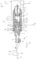
- Fig. 1 shows a longitudinal section through a chisel hammer as an example of a striking hand tool 10.
- the hand tool may additionally be suitable for drilling.
- the hand tool 10 has a tool holder 11 and a motor-driven pneumatic impact mechanism 12.
- the tool holder 11 includes a sleeve 13 for receiving a shaft of a tool.
- a locking mechanism 14 serves to lock the tool in the sleeve 13, wherein the tool 100 remains axially movable along a striking axis 15.
- FIG. 1 An embodiment of a pneumatic percussion mechanism 12 is in two positions in Fig. 1 shown.
- Hand tool 10 is supported by the tool 100 on a base 101, in the left half of Fig. 1 the tool 100 does not touch a substrate 101.
- the striking mechanism 12 has a striking tube 16, in which a excitation element 17 and a striking body 18 along the striking axis 15 are movable.
- the excitation element 17 is coupled via a drive train 19 to a motor 20.
- a pneumatic space 21 between the driven excitation element 17 and the impactor 18 couples the impactor 18 to the movement of the excitation element 17.
- an anvil guide 22 Adjacent to the impact tube 16, an anvil guide 22 is arranged with a machine-side stop 23 and a tool-side stop 25 staggered in the direction of impact 24.
- An anvil 26 is axially movable in the anvil guide 22, limited between an operating position 27 and a rest position 28 out.
- An annular protuberance 29 on a longitudinal side 30 of the anvil 26 abuts in the operating position 27 on the machine-side stop 23 and in the rest position 28 on the tool-side stop 25.
- the mass of the participating body and the periodicity of the movement of the excitation element are designed for a point of impact defined by the anvil 26 adjacent to the machine-side stop 23 is.
- the tool is pressed against the ground or a workpiece.
- the contact force causes the tool and the anvil 26 to be displaced against the direction of impact 24 into the operating position 27, i. until the anvil 26 abuts against the machine-side stop 23.
- a coil spring 32 is applied with its tool-side end 33.
- the helical spring 32 is oriented with its axis parallel to the impact axis 15 of the power tool 10.
- the coil spring 32 may be concentric with the anvil 26.
- a machine-side end 34 of the Coil spring 32 abuts an abutment point 35 of the anvil guide 22.
- the coil spring 32 exerts a force on the anvil 26 in the direction of the tool 100.
- the coil spring 32 is tensioned when the anvil 26 abuts against the machine-side stop 23 of the anvil guide 22.
- the coil spring 32 thus presses the anvil 26 out of its operating position 27.
- the anvil 26 can be advanced to the tool-side stop 25 by the coil spring 32.
- radial ventilation openings 37 are introduced.
- the ventilation openings 37 are covered by the impactor 18 when the anvil 26 abuts against the machine-side stop 23. Otherwise, when the anvil 26 is in the direction of impact 24, e.g. due to the coil spring 32 has advanced, the impactor 18 in the direction of impact 24 can advance beyond the ventilation openings 37 addition.
- the pressure in the pneumatic chamber 21 is equalized by the ventilation openings 37 to the ambient pressure. A power transmission from the excitation element 17 to the impactor 18 is interrupted.
- the spring force of the coil spring 32 is significantly lower than the usual contact pressure of the tool 100 on the substrate 101. As soon as a user applies the power tool 10 with the tool to the ground, the coil spring 32 is compressed so far that the anvil 26 on the machine-side stop 23rd the anvil guide 22 is applied, ie in operating position 27 is.
- the spring force of the coil spring 32 is, for example, less than 10% of the weight of the power tool 10. However, the spring force is sufficiently dimensioned to move the anvil 26 and a voltage applied to the anvil 26 tool 100 against the frictional forces in the direction of impact 24.
- the illustrated pneumatic impact mechanism 12 is only an example.
- the excitation element 17 may also be cup-shaped instead of a piston-like element, the impactor 18 may be formed laterally encompassing. Alternatively, the impactor 18 cup-shaped, the excitation element 17 may be formed laterally encompassing.
- a coil spring 32 and a leaf spring 26 can move the anvil between operating position and rest position.
Landscapes
- Engineering & Computer Science (AREA)
- Mechanical Engineering (AREA)
- Percussive Tools And Related Accessories (AREA)
Applications Claiming Priority (1)
| Application Number | Priority Date | Filing Date | Title |
|---|---|---|---|
| DE102009046479A DE102009046479A1 (de) | 2009-11-06 | 2009-11-06 | Handwerkzeugmaschine |
Publications (1)
| Publication Number | Publication Date |
|---|---|
| EP2319661A1 true EP2319661A1 (fr) | 2011-05-11 |
Family
ID=43499875
Family Applications (1)
| Application Number | Title | Priority Date | Filing Date |
|---|---|---|---|
| EP10188569A Withdrawn EP2319661A1 (fr) | 2009-11-06 | 2010-10-22 | Machine-outil portative |
Country Status (3)
| Country | Link |
|---|---|
| US (1) | US20110108301A1 (fr) |
| EP (1) | EP2319661A1 (fr) |
| DE (1) | DE102009046479A1 (fr) |
Families Citing this family (6)
| Publication number | Priority date | Publication date | Assignee | Title |
|---|---|---|---|---|
| DE102009008191A1 (de) * | 2009-01-30 | 2010-08-05 | Hilti Aktiengesellschaft | Werkzeughalterung |
| DE102012210088A1 (de) * | 2012-06-15 | 2013-12-19 | Hilti Aktiengesellschaft | Werkzeugmaschine |
| US10507568B2 (en) * | 2016-12-15 | 2019-12-17 | Caterpillar Inc. | Hammer work tool having multi-position retention collar |
| US10814468B2 (en) | 2017-10-20 | 2020-10-27 | Milwaukee Electric Tool Corporation | Percussion tool |
| EP4349534A2 (fr) | 2018-01-26 | 2024-04-10 | Milwaukee Electric Tool Corporation | Outil à percussion |
| SE2230406A1 (en) * | 2022-12-09 | 2024-03-12 | Atlas Copco Ind Technique Ab | Hand-held percussive tool |
Citations (3)
| Publication number | Priority date | Publication date | Assignee | Title |
|---|---|---|---|---|
| DE2416182A1 (de) * | 1974-04-03 | 1975-10-23 | Licentia Gmbh | Bohrhammer mit einer vorrichtung zum umschalten von schlagbohrbetrieb auf normalbohrbetrieb und umgekehrt |
| DE10260710A1 (de) * | 2002-12-23 | 2004-07-01 | Robert Bosch Gmbh | Bohr- oder Schlaghammer |
| DE102007062798A1 (de) * | 2007-12-27 | 2009-07-02 | Robert Bosch Gmbh | Handwerkzeugmaschine |
Family Cites Families (17)
| Publication number | Priority date | Publication date | Assignee | Title |
|---|---|---|---|---|
| US660411A (en) * | 1900-04-13 | 1900-10-23 | Robert Blum | Dental plugger. |
| US1800465A (en) * | 1927-03-14 | 1931-04-14 | Mccrosky Tool Corp | Power hammer |
| US1901779A (en) * | 1928-09-19 | 1933-03-14 | Mccrosky Tool Corp | Power hammer |
| US2178246A (en) * | 1937-12-02 | 1939-10-31 | Charles L Towle | Pneumatic percussion tool |
| US2533487A (en) * | 1946-08-15 | 1950-12-12 | Chicago Pneumatic Tool Co | Gas hammer |
| US2638749A (en) * | 1951-01-19 | 1953-05-19 | Henry J Clay | Electropneumatic hammering device |
| US4113035A (en) * | 1977-04-21 | 1978-09-12 | Licentia Patent-Verwaltungs-G.M.B.H. | Hammer drill with drive and percussion elements accommodated in a cylinder |
| US4582144A (en) * | 1984-04-25 | 1986-04-15 | Makita Electric Works, Ltd. | Percussive tools |
| JP3450558B2 (ja) * | 1995-12-25 | 2003-09-29 | 株式会社マキタ | 電動工具 |
| US5954140A (en) * | 1997-06-18 | 1999-09-21 | Milwaukee Electric Tool Corporation | Rotary hammer with improved pneumatic drive system |
| DE19833650A1 (de) * | 1998-07-25 | 2000-01-27 | Hilti Ag | Handbohrgerät |
| DE19933972A1 (de) * | 1999-07-20 | 2001-01-25 | Bosch Gmbh Robert | Bohr- oder Schlaghammer |
| ATE256533T1 (de) * | 2001-03-07 | 2004-01-15 | Black & Decker Inc | Hammer |
| JP4016772B2 (ja) * | 2001-11-16 | 2007-12-05 | 日立工機株式会社 | ハンマドリル |
| JP3976187B2 (ja) * | 2002-11-20 | 2007-09-12 | 株式会社マキタ | ハンマードリル |
| JP4179159B2 (ja) * | 2003-12-18 | 2008-11-12 | 日立工機株式会社 | 打撃工具 |
| US7383895B2 (en) * | 2005-08-19 | 2008-06-10 | Makita Corporation | Impact power tool |
-
2009
- 2009-11-06 DE DE102009046479A patent/DE102009046479A1/de not_active Ceased
-
2010
- 2010-10-22 EP EP10188569A patent/EP2319661A1/fr not_active Withdrawn
- 2010-11-06 US US12/927,055 patent/US20110108301A1/en not_active Abandoned
Patent Citations (3)
| Publication number | Priority date | Publication date | Assignee | Title |
|---|---|---|---|---|
| DE2416182A1 (de) * | 1974-04-03 | 1975-10-23 | Licentia Gmbh | Bohrhammer mit einer vorrichtung zum umschalten von schlagbohrbetrieb auf normalbohrbetrieb und umgekehrt |
| DE10260710A1 (de) * | 2002-12-23 | 2004-07-01 | Robert Bosch Gmbh | Bohr- oder Schlaghammer |
| DE102007062798A1 (de) * | 2007-12-27 | 2009-07-02 | Robert Bosch Gmbh | Handwerkzeugmaschine |
Also Published As
| Publication number | Publication date |
|---|---|
| DE102009046479A1 (de) | 2011-05-19 |
| US20110108301A1 (en) | 2011-05-12 |
Similar Documents
| Publication | Publication Date | Title |
|---|---|---|
| EP2319661A1 (fr) | Machine-outil portative | |
| DE19933972A1 (de) | Bohr- oder Schlaghammer | |
| EP1952950A2 (fr) | Outil électroportatif amortisseur d'oscillations | |
| EP2089192B1 (fr) | Unité à masses oscillantes pour des machines-outils à main pourvues d'un dispositif de frappe | |
| DE2917475A1 (de) | Bohr- oder meisselhammer | |
| EP2017038A1 (fr) | Outil manuel à percussion pneumatique | |
| DE2165066B2 (de) | Drehschlagbohrmaschine | |
| DE60226184T2 (de) | Schlaghammer | |
| DE2207961C2 (de) | Einrichtung an einem tragbaren, motorisch angetrieben Gesteinsaufbruchhammer zur axial beweglichen Führung eines Werkzeugs | |
| DE102004022623A1 (de) | Handwerkzeugmaschine mit einem Schlagwerk | |
| EP0266305B1 (fr) | Marteau de forage avec mécanisme de percussion | |
| EP0663270B1 (fr) | Marteau à percussion rotative et/ou rectiligne | |
| DE102011089921A1 (de) | Handwerkzeugvorrichtung | |
| EP1886767A2 (fr) | Machine-outil manuelle dotée d'une sonnette pneumatique | |
| EP1340596A1 (fr) | Mécanisme de percussion à ressort pneumatique | |
| DE2726214A1 (de) | Bohrhammer mit pneumatisch angetriebenem schlagkolben | |
| EP0218547B1 (fr) | Marteau pour forer ou buriner | |
| EP1618999A1 (fr) | marteau perforateur et/ou marteau-burineur | |
| EP3231560A1 (fr) | Machine-outil portative | |
| EP0375917A1 (fr) | Perceuse | |
| DE584074C (de) | Heft- oder Nagelmaschine | |
| EP3898117B1 (fr) | Machine-outil de burinage portative | |
| EP2921265A1 (fr) | Machine-outil portative | |
| DE2364344A1 (de) | Elektromotorisch betriebener federhammer, insbesondere bohrhammer | |
| DE1602006A1 (de) | Angetriebenes oder kraftbetaetigtes Werkzeug |
Legal Events
| Date | Code | Title | Description |
|---|---|---|---|
| PUAI | Public reference made under article 153(3) epc to a published international application that has entered the european phase |
Free format text: ORIGINAL CODE: 0009012 |
|
| AK | Designated contracting states |
Kind code of ref document: A1 Designated state(s): AL AT BE BG CH CY CZ DE DK EE ES FI FR GB GR HR HU IE IS IT LI LT LU LV MC MK MT NL NO PL PT RO RS SE SI SK SM TR |
|
| AX | Request for extension of the european patent |
Extension state: BA ME |
|
| STAA | Information on the status of an ep patent application or granted ep patent |
Free format text: STATUS: THE APPLICATION IS DEEMED TO BE WITHDRAWN |
|
| 18D | Application deemed to be withdrawn |
Effective date: 20111112 |