EP3180165B1 - Procéde optimisé pour une ancre extensible - Google Patents
Procéde optimisé pour une ancre extensible Download PDFInfo
- Publication number
- EP3180165B1 EP3180165B1 EP15750401.0A EP15750401A EP3180165B1 EP 3180165 B1 EP3180165 B1 EP 3180165B1 EP 15750401 A EP15750401 A EP 15750401A EP 3180165 B1 EP3180165 B1 EP 3180165B1
- Authority
- EP
- European Patent Office
- Prior art keywords
- expansion anchor
- expansion
- machine tool
- anchor
- speed
- Prior art date
- Legal status (The legal status is an assumption and is not a legal conclusion. Google has not performed a legal analysis and makes no representation as to the accuracy of the status listed.)
- Active
Links
- 238000000034 method Methods 0.000 title claims description 24
- 230000007246 mechanism Effects 0.000 claims description 4
- 230000007480 spreading Effects 0.000 description 11
- 230000008569 process Effects 0.000 description 7
- 239000000463 material Substances 0.000 description 5
- 230000035939 shock Effects 0.000 description 5
- 230000000694 effects Effects 0.000 description 4
- 210000000078 claw Anatomy 0.000 description 3
- 230000001419 dependent effect Effects 0.000 description 3
- 238000009527 percussion Methods 0.000 description 2
- 230000036316 preload Effects 0.000 description 2
- 230000004044 response Effects 0.000 description 2
- 230000004913 activation Effects 0.000 description 1
- 230000007423 decrease Effects 0.000 description 1
- 238000001514 detection method Methods 0.000 description 1
- 229910052500 inorganic mineral Inorganic materials 0.000 description 1
- 230000013011 mating Effects 0.000 description 1
- 239000011707 mineral Substances 0.000 description 1
Images
Classifications
-
- B—PERFORMING OPERATIONS; TRANSPORTING
- B25—HAND TOOLS; PORTABLE POWER-DRIVEN TOOLS; MANIPULATORS
- B25B—TOOLS OR BENCH DEVICES NOT OTHERWISE PROVIDED FOR, FOR FASTENING, CONNECTING, DISENGAGING OR HOLDING
- B25B21/00—Portable power-driven screw or nut setting or loosening tools; Attachments for drilling apparatus serving the same purpose
- B25B21/02—Portable power-driven screw or nut setting or loosening tools; Attachments for drilling apparatus serving the same purpose with means for imparting impact to screwdriver blade or nut socket
-
- B—PERFORMING OPERATIONS; TRANSPORTING
- B25—HAND TOOLS; PORTABLE POWER-DRIVEN TOOLS; MANIPULATORS
- B25B—TOOLS OR BENCH DEVICES NOT OTHERWISE PROVIDED FOR, FOR FASTENING, CONNECTING, DISENGAGING OR HOLDING
- B25B23/00—Details of, or accessories for, spanners, wrenches, screwdrivers
- B25B23/14—Arrangement of torque limiters or torque indicators in wrenches or screwdrivers
- B25B23/147—Arrangement of torque limiters or torque indicators in wrenches or screwdrivers specially adapted for electrically operated wrenches or screwdrivers
- B25B23/1475—Arrangement of torque limiters or torque indicators in wrenches or screwdrivers specially adapted for electrically operated wrenches or screwdrivers for impact wrenches or screwdrivers
-
- B—PERFORMING OPERATIONS; TRANSPORTING
- B25—HAND TOOLS; PORTABLE POWER-DRIVEN TOOLS; MANIPULATORS
- B25B—TOOLS OR BENCH DEVICES NOT OTHERWISE PROVIDED FOR, FOR FASTENING, CONNECTING, DISENGAGING OR HOLDING
- B25B31/00—Hand tools for applying fasteners
Definitions
- the present invention relates to a method for setting an expansion anchor by means of a machine tool, in particular a impact wrench. Moreover, the present invention relates to a machine tool, in particular an impact wrench, for carrying out this method, comprising an input device for detecting a type of expansion anchor or a tightening torque for the expansion anchor, a striking mechanism for generating and on the expansion anchor transferable rotary strikes, a device for detecting a rotation angle of an output shaft of the machine tool and a control device.
- Expansion anchors are inserted into a pre-drilled hole and then clamped by default in the hole by means of a torque wrench.
- the use of a torque wrench proves to be necessary because a user can not look at the expansion anchor inserted in the hole, whether it is properly braced, i. is set.
- a torque wrench proves to be necessary because a user can not look at the expansion anchor inserted in the hole, whether it is properly braced, i. is set.
- the manufacturers of the expansion anchor accordingly indicate an associated tightening torque which is to be set on the torque wrench for setting.
- a setting method for an expansion anchor and an impact wrench for setting a spreading anchor according to the prior art, for example, in the German patent application DE 10 2011 005 079 A1 disclosed.
- This prior art document describes a setting method for an expansion anchor by means of an impact wrench in which rotational impacts are repeatedly exerted on the expansion anchor. A repetition rate of the rotary impacts is set as a function of a predetermined torque for spreading an expansion sleeve of the expansion anchor.
- the impact wrench sets the application of rotational shocks when a detected average speed falls below a threshold of a nut of the expansion anchor.
- the loss of preload force is probably caused by the very high speed of the setting process.
- torque is usually applied at a plurality of intervals over a period of about 20 seconds.
- the return movement is carried out with the torque wrench, local stress peaks in the material (for example concrete) can already be reduced.
- the resulting loss of prestressing force is compensated again.
- a machine tool in particular a impact wrench
- a machine tool in particular an impact wrench
- a machine tool in particular an impact wrench, is provided for carrying out this method, comprising an input device for detecting a type of expansion anchor or tightening torque for the expansion anchor, a percussion mechanism for generating rotational shocks which can be transmitted to the expansion anchor, means for detecting a rotation angle per time interval of an output shaft of the machine tool and a control device.
- the machine tool is characterized in that the control device is configured to set a generated in the machine tool first speed, which dependent on the first speed rotational strokes on the expansion anchor for spreading an expansion of the expansion anchor are exercisable to a rotation angle per time interval of the output shaft of the machine tool predetermined threshold falls below and for adjusting a generated in the machine tool compared to the first speed reduced second speed, whereby for a predetermined period of the second speed-dependent rotational shocks on the expansible anchor for spreading the expansion of the expansion anchor can be exercised.
- a re-tensioning can be generated on the expansion anchor, whereby the setting effects can be compensated without the biasing force in the expansion anchor can be further increased.
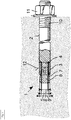
- Fig. 1 shows an exemplary expansion anchor 1 consisting of a pull rod 2 and an expansion sleeve 3.
- the expansion sleeve 3 circumferentially surrounds a cylindrical portion 4 of the tie rod 2.
- An outer diameter 5 of the cylindrical portion 4 is preferably slightly smaller than an inner diameter 6 of the expansion sleeve 3, whereby the pull rod 2 is axially movable relative to the Aufspreizelement 3.
- the cylindrical section 4 merges into a conical section 7, which forms an expansion body 8 for spreading the expansion sleeve 3.
- the largest diameter of the conical section 7 is greater than the inner diameter 6 of the expansion sleeve 3 and preferably less than an outer diameter 9 of the expansion 3.
- a thread 10 is provided, via which a tensile force can be introduced.
- the thread 10 serves at the same time a fastening of loads.
- the expansion anchor 1 with the expansion body 8 is inserted into a borehole with a diameter slightly smaller than the outer diameter of the unexpanded expansion sleeve 3.
- a nut 11 is screwed onto the thread 10 and tightened until the pull rod 2 together with the spreader 8 is pulled into the expansion sleeve 3.
- the expansion sleeve 3 clamps firmly to a wall 12 of the borehole.
- the expansion anchor 1 is properly set when the expansion sleeve 3 is radially expanded by a certain amount. A user can recognize this when the nut 11 no longer rotates at a specified tightening torque.
- expansion anchor for example, a bolt with a mating thread that engages the thread 10 of the tie rod 2.
- the user uses a screwing tool on the bolt and pulls in this way the pull rod 2 with the spreader 8 in the expansion sleeve. 3
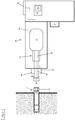
- the exemplary expansion anchors 1 can be set by means of an adapted impact wrench 20.
- the impact wrench 20 is connected in a known manner with the expansion anchor 1 so that the producible in the impact wrench 20 tightening torque is transmitted to the expansion anchor 20 and in particular to the nut 11.
- the impact wrench 20 has a percussion mechanism 21 which periodically generates rotary impacts in the direction of rotation A.
- a hammer (not shown) is supported on a drive shaft 23 by means of a helical link (not shown).
- a spring urges the hammer 22 along the output shaft 23 toward an anvil (not shown).
- the anvil is rigidly connected to an output shaft 27.
- the drive shaft 23 and the output shaft 27 are rotatable relative to each other.
- the hammer and the anvil are lengthwise the drive shaft 23 projecting (not shown) claws, via which the hammer can transmit torque to the anvil.
- An electric motor 29 drives the drive shaft 23 via a gear, not shown.
- One cycle of a rotary stroke has essentially the following phases.
- the claws of the hammer touch the anvil.
- the rotating drive shaft 23 pulls the hammer away from the anvil against the force of the spring spring because of the gate until the jaws are disengaged from the anvil 26.
- the hammer moves in the direction of the anvil and is thereby set by the scenery in a rotary motion.
- the claws finally strike tangentially on the anvil.
- An embodiment of the impact wrench 20 has an input device 30, by means of which a user can enter the special tightening torque of the expansion anchor 1.
- the input device 30 includes, for example, a button (not shown), a keyboard (not shown), a button (not shown), and / or a display element (not shown).
- an input device 30 may be provided, via which the user can set a type as well as the associated tightening torque for an expansion anchor.
- two buttons are provided for selecting a type or type of expansion anchor and a size of the expansion anchor.
- the selected type of expansion anchor and the associated tightening torque can be displayed, for example, in a designed as a display or multiple LEDs display element.
- a controller 35 reads the input tightening torque from the input device 30 and the detection device 33, respectively.
- the recognizer 33 may be realized in the form of a scanner, a scanner, an input panel, or the like.
- the control device 35 determines a first speed for the drive shaft 23 on the basis of the input tightening torque. For example, rotational speeds assigned to different tightening torques are stored in a memory device 36. After a user activates the electric motor 29 by means of a pushbutton (not shown), the control device 35 checks whether a rotational speed has previously been predetermined, for example by specifying the expansion anchor type or the tightening torque. The control device 35 can inhibit activation of the motor 29, for example, if no tightening torque was selected so far, but instead prompt the user for an input. The control device 35 controls the electric motor 29 such that the drive shaft 23 rotates at the predetermined first speed. The selected first rotational speed of the drive shaft 23 specifies the repetition rate of the rotational shocks.
- the impact wrench 20 starts to rotate the nut 11 with a maximum possible speed to him. After a period of time, which is preferably determined by the input type of the expansion anchor 1, the impact wrench lowers the speed to the predetermined speed in dependence on the tightening torque.
- the tightening torque is the tightening torque predetermined for the respective expansion anchor used.
- a device 39 for detecting a rotational angle per time interval of an output shaft 27 is arranged about an axis of rotation R.
- the means 39 for detecting a rotation angle per time interval of an output shaft 27 is realized by a rotation angle sensor.
- the rotation angle sensor 39 serves to detect the rotation angle per time interval of the output shaft 27 about the rotation axis R.
- the rotation angle sensor 39 may be in the form of one or more magnetic field sensors, e.g. Hall sensors, be configured.
- the detected angle of rotation per time interval of the output shaft 27 about an axis of rotation R is transmitted to the control device 35 via a connecting line 40.
- the control device 35 compares the rotation angle detected by the rotation angle sensor 39 per time interval of the output shaft 27 with threshold values for rotation angles per time interval of the output shaft 27 stored in the memory device 36. If the rotation angle detected by the rotation angle sensor 39 falls short of a predetermined threshold value per time interval of the output shaft 27, then This is an indicator that the expansion anchor can not be further rotated with the torque applied to him or with the torque acting on him of the set to the first speed wrench and properly set in the well. According to an embodiment not shown and not further described, a rotation angle sensor is not necessarily provided, since the rotation angle per time interval can be determined indirectly from the motor rotation angle with a corresponding device.
- the control device 35 the electric motor so that a second speed for the drive shaft 23 is applied.
- the second speed is less than the first speed.
- the second or lower speed generates rotational shocks with a correspondingly lower tightening torque, which is exerted on the expansible anchor for a predetermined period of time t. In this way, a re-tensioning can be generated on the expansion anchor, whereby the setting effects can be compensated without the biasing force in the expansion anchor can be further increased.
- the setting process of the expansion anchor 1 is thereby optimized, so that the expansion anchor 1 can be subjected to the highest possible tensile load in the borehole.
Claims (2)
- Procédé pour poser un élément d'ancrage expansible (1) au moyen d'une machine-outil (20), en particulier une visseuse à percussion,
caractérisé par les étapes consistant à :- exercer des percussions rotatives par l'intermédiaire de la machine-outil (20) sur un élément d'ancrage expansible (1) pour écarter une douille d'expansion (3) de l'élément d'ancrage expansible (1) en fonction d'une première vitesse de rotation générée dans la machine-outil (20) jusqu'à ce qu'un angle de rotation par intervalle de temps d'un arbre de sortie (27) de la machine-outil (20) soit inférieur à une valeur de seuil prédéfinie, et- exercer des percussions rotatives par l'intermédiaire de la machine-outil (20) sur l'élément d'ancrage expansible (1) pour écarter la douille d'expansion (3) de l'élément d'ancrage expansible (1) en fonction d'une seconde vitesse de rotation générée dans la machine-outil (20) et réduite par rapport à la première vitesse de rotation, pendant une durée (t) prédéfinie. - Machine-outil (20), en particulier une visseuse à percussion, pour mettre en oeuvre le procédé selon la revendication 1, contenant :- un dispositif d'entrée (30) pour détecter un type d'un élément d'ancrage expansible (1) ou un couple de démarrage pour l'élément d'ancrage expansible (1),- un mécanisme de percussion (21) pour générer des percussions rotatives pouvant être transmises par et sur l'élément d'ancrage expansible (1),- un dispositif (39) pour détecter un angle de rotation par intervalle de temps d'un arbre de sortie (27) de la machine-outil (20), et- un dispositif de commande (35)caractérisé en ce que le dispositif de commande (35) est configuré pour régler une première vitesse de rotation générée dans la machine-outil (20), en sorte que des percussions rotatives dépendant de la première vitesse de rotation peuvent être exercées à l'élément d'ancrage expansible (1) pour écarter une douille d'expansion (3) de l'élément d'ancrage expansible (1) jusqu'à ce qu'un angle de rotation par intervalle de temps de l'arbre de sortie (27) de la machine-outil (20) soit inférieur à une valeur de seuil prédéfinie, et pour régler une seconde vitesse de rotation générée dans la machine-outil (20) et réduite par rapport à la première vitesse de rotation, en sorte que pendant une durée (t) prédéfinie, des percussions rotatives dépendant de la seconde vitesse de rotation peuvent être exercées sur l'élément d'ancrage expansible (1) pour écarter la douille d'expansion (3) de l'élément d'ancrage expansible (1).
Applications Claiming Priority (2)
| Application Number | Priority Date | Filing Date | Title |
|---|---|---|---|
| EP14180630.7A EP2985117A1 (fr) | 2014-08-12 | 2014-08-12 | Procéde optimisé pour une ancre extensible |
| PCT/EP2015/068416 WO2016023883A1 (fr) | 2014-08-12 | 2015-08-11 | Procédé de mise en place amélioré pour élément d'ancrage à expansion |
Publications (2)
| Publication Number | Publication Date |
|---|---|
| EP3180165A1 EP3180165A1 (fr) | 2017-06-21 |
| EP3180165B1 true EP3180165B1 (fr) | 2018-06-20 |
Family
ID=51301169
Family Applications (2)
| Application Number | Title | Priority Date | Filing Date |
|---|---|---|---|
| EP14180630.7A Withdrawn EP2985117A1 (fr) | 2014-08-12 | 2014-08-12 | Procéde optimisé pour une ancre extensible |
| EP15750401.0A Active EP3180165B1 (fr) | 2014-08-12 | 2015-08-11 | Procéde optimisé pour une ancre extensible |
Family Applications Before (1)
| Application Number | Title | Priority Date | Filing Date |
|---|---|---|---|
| EP14180630.7A Withdrawn EP2985117A1 (fr) | 2014-08-12 | 2014-08-12 | Procéde optimisé pour une ancre extensible |
Country Status (5)
| Country | Link |
|---|---|
| US (1) | US20170232589A1 (fr) |
| EP (2) | EP2985117A1 (fr) |
| JP (1) | JP6668328B2 (fr) |
| CN (1) | CN106457534B (fr) |
| WO (1) | WO2016023883A1 (fr) |
Families Citing this family (7)
| Publication number | Priority date | Publication date | Assignee | Title |
|---|---|---|---|---|
| US10646982B2 (en) * | 2015-12-17 | 2020-05-12 | Milwaukee Electric Tool Corporation | System and method for configuring a power tool with an impact mechanism |
| TWI734749B (zh) | 2016-02-25 | 2021-08-01 | 美商米沃奇電子工具公司 | 包括輸出位置感測器之動力工具 |
| SE541543C2 (en) * | 2017-11-17 | 2019-10-29 | Atlas Copco Ind Technique Ab | Method for controlling a tightening tool |
| EP3501740A1 (fr) | 2017-12-20 | 2019-06-26 | HILTI Aktiengesellschaft | Procédé de pose pour raccord à vis au moyen de clé à percussion |
| EP3501743A1 (fr) * | 2017-12-20 | 2019-06-26 | HILTI Aktiengesellschaft | Procédé de pose pour élément d'ancrage à expansion au moyen de la clé à percussion |
| EP3501742A1 (fr) * | 2017-12-20 | 2019-06-26 | HILTI Aktiengesellschaft | Procédé de pose pour élément d'ancrage à expansion au moyen de la clé à percussion |
| EP3501741A1 (fr) * | 2017-12-20 | 2019-06-26 | HILTI Aktiengesellschaft | Procédé de pose pour raccord à vis au moyen de clé à percussion |
Family Cites Families (13)
| Publication number | Priority date | Publication date | Assignee | Title |
|---|---|---|---|---|
| DE10045985A1 (de) * | 2000-09-16 | 2002-03-28 | Hilti Ag | Elektrohandwerkzeuggerät mt Drehmomentkontrolle |
| JP4400303B2 (ja) * | 2004-05-12 | 2010-01-20 | パナソニック電工株式会社 | インパクト回転工具 |
| US7552781B2 (en) * | 2004-10-20 | 2009-06-30 | Black & Decker Inc. | Power tool anti-kickback system with rotational rate sensor |
| JP4339275B2 (ja) * | 2005-05-12 | 2009-10-07 | 株式会社エスティック | インパクト式のネジ締め装置の制御方法および装置 |
| JP2010247289A (ja) * | 2009-04-17 | 2010-11-04 | Dual Denshi Kogyo:Kk | ネジ締め方法 |
| JP5441003B2 (ja) * | 2009-10-01 | 2014-03-12 | 日立工機株式会社 | 回転打撃工具 |
| JP2012045665A (ja) * | 2010-08-26 | 2012-03-08 | Toyota Motor Corp | 打撃式締め付け工具 |
| DE102010062014B3 (de) * | 2010-11-26 | 2012-05-10 | Hilti Aktiengesellschaft | Handwerkzeugmaschine |
| US20120234566A1 (en) * | 2010-11-30 | 2012-09-20 | Hitachi Koki Co., Ltd., | Impact tool |
| DE102011005079A1 (de) * | 2011-03-04 | 2012-09-06 | Hilti Aktiengesellschaft | Setzverfahren für einen Spreizanker und Schlagschrauber zum Setzen eines Spreizankers |
| JP2013188812A (ja) * | 2012-03-13 | 2013-09-26 | Hitachi Koki Co Ltd | インパクト工具 |
| JP2014020120A (ja) * | 2012-07-19 | 2014-02-03 | Maeda Corp | アンカー筋及びこれを用いたスラブ接合構造 |
| EP2985118A1 (fr) * | 2014-08-12 | 2016-02-17 | HILTI Aktiengesellschaft | Procéde optimisé pour une ancre extensible |
-
2014
- 2014-08-12 EP EP14180630.7A patent/EP2985117A1/fr not_active Withdrawn
-
2015
- 2015-08-11 WO PCT/EP2015/068416 patent/WO2016023883A1/fr active Application Filing
- 2015-08-11 US US15/503,264 patent/US20170232589A1/en not_active Abandoned
- 2015-08-11 EP EP15750401.0A patent/EP3180165B1/fr active Active
- 2015-08-11 JP JP2017507388A patent/JP6668328B2/ja active Active
- 2015-08-11 CN CN201580026575.3A patent/CN106457534B/zh active Active
Non-Patent Citations (1)
| Title |
|---|
| None * |
Also Published As
| Publication number | Publication date |
|---|---|
| JP6668328B2 (ja) | 2020-03-18 |
| CN106457534A (zh) | 2017-02-22 |
| CN106457534B (zh) | 2019-03-15 |
| JP2017523056A (ja) | 2017-08-17 |
| WO2016023883A1 (fr) | 2016-02-18 |
| EP2985117A1 (fr) | 2016-02-17 |
| US20170232589A1 (en) | 2017-08-17 |
| EP3180165A1 (fr) | 2017-06-21 |
Similar Documents
| Publication | Publication Date | Title |
|---|---|---|
| EP3180166B1 (fr) | Procéde optimisé pour une ancre extensible | |
| EP3180165B1 (fr) | Procéde optimisé pour une ancre extensible | |
| EP2495076B1 (fr) | Procédé de fixation pour une ancre extensible et vis à percussion pour la fixation d'une ancre extensible | |
| EP2243599B1 (fr) | Visseuse à percussion et procédé de commande pour une visseuse à percussion | |
| DE102014002986B3 (de) | Verfahren und Vorrichtung zum Einbringen von Schraubfundamenten ins Erdreich | |
| DE102010062014B3 (de) | Handwerkzeugmaschine | |
| DE60011746T2 (de) | Befestigungselement, antriebsvorrichtung zur ausführung des befestigungselements und bohrmeisel zum herstellen von bohrlöchern mit hinterschneidung | |
| DE102011017671A1 (de) | Handwerkzeugmaschine | |
| EP3727756B1 (fr) | Procédé de pose pour élément d'ancrage à expansion au moyen de la clé à percussion | |
| DE102014109412B3 (de) | Reiblager zwischen Läufer und Amboss in einem Schlagschrauber | |
| DE102013206388A1 (de) | Anker mit Spreizbereich und Schneidgewinde | |
| EP1785231A2 (fr) | Outil de vissage à régulation de vitesse de rotation et méthode de régulation de vitesse pour un outil de vissage | |
| EP3727757B1 (fr) | Procédé de pose pour élément d'ancrage à expansion au moyen de la clé à percussion | |
| DE102010038210A1 (de) | Drehmomentübertragungsvorrichtung zur Verwendung mit einem Drehschlagschrauber | |
| EP3648928B1 (fr) | Outil de pose, kit pour système d'outil de pose et système d'outil de pose | |
| EP2867544B1 (fr) | Boulon à expansion | |
| DE3913299A1 (de) | Verfahren und vorrichtung zum formen eines gewindes in gestein oder beton | |
| EP3727758B1 (fr) | Procédé de pose pour raccord à vis au moyen de clé à percussion | |
| EP2921263A1 (fr) | Reconnaissance de comportement au choc en fonction de la charge | |
| WO2019121754A1 (fr) | Procédé de mise en place d'un assemblage vissé au moyen d'une visseuse à percussion | |
| DE102021213370A1 (de) | Vibrationsbohrhammer |
Legal Events
| Date | Code | Title | Description |
|---|---|---|---|
| PUAI | Public reference made under article 153(3) epc to a published international application that has entered the european phase |
Free format text: ORIGINAL CODE: 0009012 |
|
| 17P | Request for examination filed |
Effective date: 20170313 |
|
| AK | Designated contracting states |
Kind code of ref document: A1 Designated state(s): AL AT BE BG CH CY CZ DE DK EE ES FI FR GB GR HR HU IE IS IT LI LT LU LV MC MK MT NL NO PL PT RO RS SE SI SK SM TR |
|
| AX | Request for extension of the european patent |
Extension state: BA ME |
|
| DAV | Request for validation of the european patent (deleted) | ||
| DAX | Request for extension of the european patent (deleted) | ||
| REG | Reference to a national code |
Ref country code: DE Ref legal event code: R079 Ref document number: 502015004768 Country of ref document: DE Free format text: PREVIOUS MAIN CLASS: B25B0021020000 Ipc: B25B0023147000 |
|
| GRAP | Despatch of communication of intention to grant a patent |
Free format text: ORIGINAL CODE: EPIDOSNIGR1 |
|
| RIC1 | Information provided on ipc code assigned before grant |
Ipc: B25B 23/147 20060101AFI20180307BHEP Ipc: B25B 31/00 20060101ALI20180307BHEP Ipc: B25B 21/02 20060101ALI20180307BHEP |
|
| INTG | Intention to grant announced |
Effective date: 20180321 |
|
| GRAS | Grant fee paid |
Free format text: ORIGINAL CODE: EPIDOSNIGR3 |
|
| GRAA | (expected) grant |
Free format text: ORIGINAL CODE: 0009210 |
|
| AK | Designated contracting states |
Kind code of ref document: B1 Designated state(s): AL AT BE BG CH CY CZ DE DK EE ES FI FR GB GR HR HU IE IS IT LI LT LU LV MC MK MT NL NO PL PT RO RS SE SI SK SM TR |
|
| REG | Reference to a national code |
Ref country code: GB Ref legal event code: FG4D Free format text: NOT ENGLISH |
|
| REG | Reference to a national code |
Ref country code: IE Ref legal event code: FG4D Free format text: LANGUAGE OF EP DOCUMENT: GERMAN |
|
| REG | Reference to a national code |
Ref country code: AT Ref legal event code: REF Ref document number: 1010243 Country of ref document: AT Kind code of ref document: T Effective date: 20180715 |
|
| REG | Reference to a national code |
Ref country code: DE Ref legal event code: R096 Ref document number: 502015004768 Country of ref document: DE |
|
| REG | Reference to a national code |
Ref country code: FR Ref legal event code: PLFP Year of fee payment: 4 |
|
| REG | Reference to a national code |
Ref country code: NL Ref legal event code: MP Effective date: 20180620 |
|
| PG25 | Lapsed in a contracting state [announced via postgrant information from national office to epo] |
Ref country code: SE Free format text: LAPSE BECAUSE OF FAILURE TO SUBMIT A TRANSLATION OF THE DESCRIPTION OR TO PAY THE FEE WITHIN THE PRESCRIBED TIME-LIMIT Effective date: 20180620 Ref country code: FI Free format text: LAPSE BECAUSE OF FAILURE TO SUBMIT A TRANSLATION OF THE DESCRIPTION OR TO PAY THE FEE WITHIN THE PRESCRIBED TIME-LIMIT Effective date: 20180620 Ref country code: NO Free format text: LAPSE BECAUSE OF FAILURE TO SUBMIT A TRANSLATION OF THE DESCRIPTION OR TO PAY THE FEE WITHIN THE PRESCRIBED TIME-LIMIT Effective date: 20180920 Ref country code: BG Free format text: LAPSE BECAUSE OF FAILURE TO SUBMIT A TRANSLATION OF THE DESCRIPTION OR TO PAY THE FEE WITHIN THE PRESCRIBED TIME-LIMIT Effective date: 20180920 Ref country code: LT Free format text: LAPSE BECAUSE OF FAILURE TO SUBMIT A TRANSLATION OF THE DESCRIPTION OR TO PAY THE FEE WITHIN THE PRESCRIBED TIME-LIMIT Effective date: 20180620 |
|
| REG | Reference to a national code |
Ref country code: LT Ref legal event code: MG4D |
|
| PG25 | Lapsed in a contracting state [announced via postgrant information from national office to epo] |
Ref country code: GR Free format text: LAPSE BECAUSE OF FAILURE TO SUBMIT A TRANSLATION OF THE DESCRIPTION OR TO PAY THE FEE WITHIN THE PRESCRIBED TIME-LIMIT Effective date: 20180921 Ref country code: HR Free format text: LAPSE BECAUSE OF FAILURE TO SUBMIT A TRANSLATION OF THE DESCRIPTION OR TO PAY THE FEE WITHIN THE PRESCRIBED TIME-LIMIT Effective date: 20180620 Ref country code: LV Free format text: LAPSE BECAUSE OF FAILURE TO SUBMIT A TRANSLATION OF THE DESCRIPTION OR TO PAY THE FEE WITHIN THE PRESCRIBED TIME-LIMIT Effective date: 20180620 Ref country code: RS Free format text: LAPSE BECAUSE OF FAILURE TO SUBMIT A TRANSLATION OF THE DESCRIPTION OR TO PAY THE FEE WITHIN THE PRESCRIBED TIME-LIMIT Effective date: 20180620 |
|
| PG25 | Lapsed in a contracting state [announced via postgrant information from national office to epo] |
Ref country code: NL Free format text: LAPSE BECAUSE OF FAILURE TO SUBMIT A TRANSLATION OF THE DESCRIPTION OR TO PAY THE FEE WITHIN THE PRESCRIBED TIME-LIMIT Effective date: 20180620 |
|
| PG25 | Lapsed in a contracting state [announced via postgrant information from national office to epo] |
Ref country code: CZ Free format text: LAPSE BECAUSE OF FAILURE TO SUBMIT A TRANSLATION OF THE DESCRIPTION OR TO PAY THE FEE WITHIN THE PRESCRIBED TIME-LIMIT Effective date: 20180620 Ref country code: RO Free format text: LAPSE BECAUSE OF FAILURE TO SUBMIT A TRANSLATION OF THE DESCRIPTION OR TO PAY THE FEE WITHIN THE PRESCRIBED TIME-LIMIT Effective date: 20180620 Ref country code: IS Free format text: LAPSE BECAUSE OF FAILURE TO SUBMIT A TRANSLATION OF THE DESCRIPTION OR TO PAY THE FEE WITHIN THE PRESCRIBED TIME-LIMIT Effective date: 20181020 Ref country code: PL Free format text: LAPSE BECAUSE OF FAILURE TO SUBMIT A TRANSLATION OF THE DESCRIPTION OR TO PAY THE FEE WITHIN THE PRESCRIBED TIME-LIMIT Effective date: 20180620 Ref country code: EE Free format text: LAPSE BECAUSE OF FAILURE TO SUBMIT A TRANSLATION OF THE DESCRIPTION OR TO PAY THE FEE WITHIN THE PRESCRIBED TIME-LIMIT Effective date: 20180620 Ref country code: SK Free format text: LAPSE BECAUSE OF FAILURE TO SUBMIT A TRANSLATION OF THE DESCRIPTION OR TO PAY THE FEE WITHIN THE PRESCRIBED TIME-LIMIT Effective date: 20180620 |
|
| PG25 | Lapsed in a contracting state [announced via postgrant information from national office to epo] |
Ref country code: SM Free format text: LAPSE BECAUSE OF FAILURE TO SUBMIT A TRANSLATION OF THE DESCRIPTION OR TO PAY THE FEE WITHIN THE PRESCRIBED TIME-LIMIT Effective date: 20180620 Ref country code: IT Free format text: LAPSE BECAUSE OF FAILURE TO SUBMIT A TRANSLATION OF THE DESCRIPTION OR TO PAY THE FEE WITHIN THE PRESCRIBED TIME-LIMIT Effective date: 20180620 Ref country code: ES Free format text: LAPSE BECAUSE OF FAILURE TO SUBMIT A TRANSLATION OF THE DESCRIPTION OR TO PAY THE FEE WITHIN THE PRESCRIBED TIME-LIMIT Effective date: 20180620 |
|
| REG | Reference to a national code |
Ref country code: DE Ref legal event code: R097 Ref document number: 502015004768 Country of ref document: DE |
|
| PG25 | Lapsed in a contracting state [announced via postgrant information from national office to epo] |
Ref country code: MC Free format text: LAPSE BECAUSE OF FAILURE TO SUBMIT A TRANSLATION OF THE DESCRIPTION OR TO PAY THE FEE WITHIN THE PRESCRIBED TIME-LIMIT Effective date: 20180620 |
|
| PLBE | No opposition filed within time limit |
Free format text: ORIGINAL CODE: 0009261 |
|
| STAA | Information on the status of an ep patent application or granted ep patent |
Free format text: STATUS: NO OPPOSITION FILED WITHIN TIME LIMIT |
|
| PG25 | Lapsed in a contracting state [announced via postgrant information from national office to epo] |
Ref country code: LU Free format text: LAPSE BECAUSE OF NON-PAYMENT OF DUE FEES Effective date: 20180811 |
|
| REG | Reference to a national code |
Ref country code: BE Ref legal event code: MM Effective date: 20180831 |
|
| 26N | No opposition filed |
Effective date: 20190321 |
|
| REG | Reference to a national code |
Ref country code: IE Ref legal event code: MM4A |
|
| PG25 | Lapsed in a contracting state [announced via postgrant information from national office to epo] |
Ref country code: DK Free format text: LAPSE BECAUSE OF FAILURE TO SUBMIT A TRANSLATION OF THE DESCRIPTION OR TO PAY THE FEE WITHIN THE PRESCRIBED TIME-LIMIT Effective date: 20180620 |
|
| PG25 | Lapsed in a contracting state [announced via postgrant information from national office to epo] |
Ref country code: IE Free format text: LAPSE BECAUSE OF NON-PAYMENT OF DUE FEES Effective date: 20180811 |
|
| PG25 | Lapsed in a contracting state [announced via postgrant information from national office to epo] |
Ref country code: SI Free format text: LAPSE BECAUSE OF FAILURE TO SUBMIT A TRANSLATION OF THE DESCRIPTION OR TO PAY THE FEE WITHIN THE PRESCRIBED TIME-LIMIT Effective date: 20180620 Ref country code: BE Free format text: LAPSE BECAUSE OF NON-PAYMENT OF DUE FEES Effective date: 20180831 |
|
| PG25 | Lapsed in a contracting state [announced via postgrant information from national office to epo] |
Ref country code: AL Free format text: LAPSE BECAUSE OF FAILURE TO SUBMIT A TRANSLATION OF THE DESCRIPTION OR TO PAY THE FEE WITHIN THE PRESCRIBED TIME-LIMIT Effective date: 20180620 |
|
| PG25 | Lapsed in a contracting state [announced via postgrant information from national office to epo] |
Ref country code: MT Free format text: LAPSE BECAUSE OF FAILURE TO SUBMIT A TRANSLATION OF THE DESCRIPTION OR TO PAY THE FEE WITHIN THE PRESCRIBED TIME-LIMIT Effective date: 20180620 |
|
| PG25 | Lapsed in a contracting state [announced via postgrant information from national office to epo] |
Ref country code: TR Free format text: LAPSE BECAUSE OF FAILURE TO SUBMIT A TRANSLATION OF THE DESCRIPTION OR TO PAY THE FEE WITHIN THE PRESCRIBED TIME-LIMIT Effective date: 20180620 |
|
| PG25 | Lapsed in a contracting state [announced via postgrant information from national office to epo] |
Ref country code: PT Free format text: LAPSE BECAUSE OF FAILURE TO SUBMIT A TRANSLATION OF THE DESCRIPTION OR TO PAY THE FEE WITHIN THE PRESCRIBED TIME-LIMIT Effective date: 20180620 |
|
| PG25 | Lapsed in a contracting state [announced via postgrant information from national office to epo] |
Ref country code: HU Free format text: LAPSE BECAUSE OF FAILURE TO SUBMIT A TRANSLATION OF THE DESCRIPTION OR TO PAY THE FEE WITHIN THE PRESCRIBED TIME-LIMIT; INVALID AB INITIO Effective date: 20150811 Ref country code: CY Free format text: LAPSE BECAUSE OF FAILURE TO SUBMIT A TRANSLATION OF THE DESCRIPTION OR TO PAY THE FEE WITHIN THE PRESCRIBED TIME-LIMIT Effective date: 20180620 Ref country code: MK Free format text: LAPSE BECAUSE OF NON-PAYMENT OF DUE FEES Effective date: 20180620 |
|
| PGFP | Annual fee paid to national office [announced via postgrant information from national office to epo] |
Ref country code: GB Payment date: 20230822 Year of fee payment: 9 Ref country code: CH Payment date: 20230902 Year of fee payment: 9 Ref country code: AT Payment date: 20230822 Year of fee payment: 9 |
|
| PGFP | Annual fee paid to national office [announced via postgrant information from national office to epo] |
Ref country code: FR Payment date: 20230825 Year of fee payment: 9 Ref country code: DE Payment date: 20230821 Year of fee payment: 9 |