EP3552995A2 - Module de travail pour un dispositif d'emballage et procédé de manipulation d'articles et / ou de matériau d'emballage - Google Patents
Module de travail pour un dispositif d'emballage et procédé de manipulation d'articles et / ou de matériau d'emballage Download PDFInfo
- Publication number
- EP3552995A2 EP3552995A2 EP18215275.1A EP18215275A EP3552995A2 EP 3552995 A2 EP3552995 A2 EP 3552995A2 EP 18215275 A EP18215275 A EP 18215275A EP 3552995 A2 EP3552995 A2 EP 3552995A2
- Authority
- EP
- European Patent Office
- Prior art keywords
- holding means
- belt
- running
- articles
- rotation
- Prior art date
- Legal status (The legal status is an assumption and is not a legal conclusion. Google has not performed a legal analysis and makes no representation as to the accuracy of the status listed.)
- Granted
Links
Images


Classifications
-
- B—PERFORMING OPERATIONS; TRANSPORTING
- B65—CONVEYING; PACKING; STORING; HANDLING THIN OR FILAMENTARY MATERIAL
- B65G—TRANSPORT OR STORAGE DEVICES, e.g. CONVEYORS FOR LOADING OR TIPPING, SHOP CONVEYOR SYSTEMS OR PNEUMATIC TUBE CONVEYORS
- B65G19/00—Conveyors comprising an impeller or a series of impellers carried by an endless traction element and arranged to move articles or materials over a supporting surface or underlying material, e.g. endless scraper conveyors
- B65G19/18—Details
- B65G19/22—Impellers, e.g. push-plates, scrapers; Guiding means therefor
- B65G19/24—Attachment of impellers to traction element
- B65G19/245—Attachment of impellers to traction element for article conveyors, e.g. for container conveyors
-
- B—PERFORMING OPERATIONS; TRANSPORTING
- B65—CONVEYING; PACKING; STORING; HANDLING THIN OR FILAMENTARY MATERIAL
- B65B—MACHINES, APPARATUS OR DEVICES FOR, OR METHODS OF, PACKAGING ARTICLES OR MATERIALS; UNPACKING
- B65B21/00—Packaging or unpacking of bottles
- B65B21/02—Packaging or unpacking of bottles in or from preformed containers, e.g. crates
- B65B21/04—Arranging, assembling, feeding, or orientating the bottles prior to introduction into, or after removal from, containers
- B65B21/06—Forming groups of bottles
-
- B—PERFORMING OPERATIONS; TRANSPORTING
- B65—CONVEYING; PACKING; STORING; HANDLING THIN OR FILAMENTARY MATERIAL
- B65B—MACHINES, APPARATUS OR DEVICES FOR, OR METHODS OF, PACKAGING ARTICLES OR MATERIALS; UNPACKING
- B65B21/00—Packaging or unpacking of bottles
- B65B21/24—Enclosing bottles in wrappers
- B65B21/245—Enclosing bottles in wrappers in flexible wrappers, e.g. foils
-
- B—PERFORMING OPERATIONS; TRANSPORTING
- B65—CONVEYING; PACKING; STORING; HANDLING THIN OR FILAMENTARY MATERIAL
- B65B—MACHINES, APPARATUS OR DEVICES FOR, OR METHODS OF, PACKAGING ARTICLES OR MATERIALS; UNPACKING
- B65B35/00—Supplying, feeding, arranging or orientating articles to be packaged
- B65B35/30—Arranging and feeding articles in groups
- B65B35/40—Arranging and feeding articles in groups by reciprocating or oscillatory pushers
- B65B35/405—Arranging and feeding articles in groups by reciprocating or oscillatory pushers linked to endless conveyors
Definitions
- the present invention relates to a working module for a packaging device and a method for handling articles and / or packaging material.
- rows of articles are moved parallel to one another, whereby successive articles may be contiguous.
- a certain number of leading articles may be briefly accelerated compared to subsequent articles.
- one-piece rods may be provided, which come into contact with the specified number of articles on the back and then accelerate the articles of the specified number in relation to the subsequent articles for a short time.
- packaging devices in which by means of such Einteilstäbe subsequent articles are delayed against the leading articles for a short time.
- a relative spacing is formed between the particular number of leading articles and subsequent articles, thereby creating groups of articles to which packaging material may subsequently be applied.
- the dividing bars are arranged on continuously moving conveyor chains.
- the respective relative distance or pitch of arranged at the circumferentially moving conveyor chains Einteilstäben each other is here matched to the respective group of articles to be formed.
- packaging devices In order to provide the respective groups of articles with packaging material, packaging devices often have a multiplicity of revolving or turning impact bars, which apply flat and optionally shrink-wrapped or stretch-formed packaging material to a respective group of articles.
- impact bars are arranged in practice for circulating or rotating movement on conveyor chains.
- Circulating conveyor chains as used in packaging devices, for example, for the movement of impact bars and / or Einteilstäben use own high initial costs and must be serviced or replaced at regular intervals. Since conveyor chains used in packaging devices consist of several individual members formed of metal, a respective operation of such a packaging device is associated with an undesirably high volume.
- a primary object of the invention can therefore be seen in particular to provide a practicable, inexpensive to implement and cost-effective means by which the disadvantages mentioned are at least partially eliminated.
- the invention relates to a trained for handling articles and / or packaging material working module for a packaging device.
- the packaging device may have a plurality of individual modules by means of which groups of articles are formed and / or by means of which packaging material is applied to articles and / or by means of which palletizable layers are transferred to an associated pallet.
- the working module can be designed in conceivable embodiments as such a module which is part of the packaging device.
- the working module comprises at least one circulating drive means. Furthermore, the working module comprises a plurality of format parts which are designed to act on articles and / or for handling packaging material. Also, the working module comprises a plurality of holding means.
- the at least one circumferentially guided drive means comprises at least one circumferentially guided belt, to which at least one circulating guided belt, the plurality of formed for acting on articles and / or handling packaging material format parts are mechanically coupled via the plurality of holding means.
- belts have lower acquisition costs compared to conveyor chains and are distinguished from conveyor chains by low-noise operation.
- the plurality of holding means in each case arranged on at least two attachment regions on at least one circulating guided belt are, wherein the respective at least two mounting portion are positioned offset from each other with respect to the circumferential course of the at least one circumferentially guided belt.
- the at least two attachment regions can be positioned spaced apart from each other on at least one circumferentially guided belt.
- each of the at least two attachment areas is assigned a bar, which respective bar is inserted into a formed by a toothing of at least one circumferentially guided belt groove and which respective bar clamping the respective holding means on at least one circumferential fixed belt.
- at least one screw connection can be provided for each strip, which passes through at least one screw the at least one circumferentially guided belt and in this case fixes the respective strip on a formed as part of the respective holding means wing.
- the plurality of holding means may form their respective at least two attachment regions spaced from one another.
- the plurality of holding means each have at least one axis of rotation about which the respective at least two attachment areas of a respective holding means are pivotable independently of one another have proved successful. By means of a pivoting movement, the plurality of holding means can thus possibly change their distance from one another.
- the at least one belt Due to the circumferential guidance of the at least one belt, it may be that a portion of the at least one circulating belt located in the region of a deflection is temporarily stretched or is temporarily reversibly elastically deformed.
- the possibly space-variable and arranged at the located in the region of the deflection lot arranged at least two mounting portions of a respective holding means can increase their relative distance and in this case the temporary stretching or the temporary reversible elastic deformation of the lot follow.
- the previously stretched portion may contract or deform the previously reversibly elastically deformed portion, wherein the at least two fixing areas of the respective holding means which are still fixed in the area of the portion maintain their relative distance from each other zoom out or approach each other.
- the working module can have at least one deflection roller and / or at least one drive roller.
- the plurality of holding means each have a common axis of rotation for the respective at least two mounting areas about which respective common axis of rotation the respective at least two mounting portion of a respective holding means are independently pivotable.
- the plurality of holding means each have a common axis of rotation for the respective at least two mounting portion about which respective common axis of rotation the respective at least two mounting portion of a respective holding means are independently pivotable, wherein the respective at least two mounting portions in the course of a respective pivoting movement to follow the common axis of rotation of a circular path.
- the at least two attachment regions can be pivoted about the respective common axis of rotation in the region of a respective deflection roller and / or drive roller.
- An axis of rotation of the deflection roller or of the drive roller and the axis of rotation can be oriented parallel or substantially parallel to one another.
- the plurality of holding means for each respective first attachment area may form a respective first pivot axis about which the respective first attachment area can be rotated.
- the plurality of holding means for a respective second attachment region may form a respective second pivot axis about which respective second pivot axis the respective second attachment region may be rotated.
- the first pivot axis and the second pivot axis of a respective holding means can be offset along the circumferential course of the respective at least one circumferentially guided belt and preferably oriented parallel to each other.
- the plurality of holding means each have a common axis of rotation for the respective at least two mounting areas about which respective common axis of rotation the respective at least two mounting portions of a respective holding means are independently pivotable.
- the plurality of retaining means for a respective first attachment portion form a respective first pivot axis about which the respective first attachment portion can be rotated and the plurality of retaining means for a respective second attachment portion form a respective second pivot axis about each respective second pivot axis the respective second attachment area can be turned.
- the first pivot axis, the second pivot axis and the common axis of rotation can be offset along the circumferential course of the respective at least one circumferentially guided belt and oriented parallel to each other.
- the common axis of rotation can in this case be arranged between the first pivot axis and the second pivot axis.
- the plurality of holding means may also provide a respective attachment designed in particular as a receptacle for a respective format part, wherein the attachment formed in particular as a receptacle and the common axis of rotation are oriented in alignment with one another.
- the respective format part itself may form the common axis of rotation or provide the common axis of rotation.
- the working module may comprise at least one preferably designed as a rail support.
- the at least one preferably designed as a rail support is positioned such that the plurality of holding means are in the course of an over the at least one belt caused and substantially linear movement with the at least one preferably designed as a rail support in surface contact.
- the plurality of holding means each have at least one laterally extending from the respective holding means running and / or sliding roller, via which respective at least one laterally projecting from the respective holding means running and / or sliding roller the respective holding means with the at least one preferably as Rail trained support is in surface contact.
- the plurality of holding means each comprise at least one first laterally extending from the respective holding means running and / or sliding roller and at least one second from the respective holding means laterally projecting running and / or sliding roller, wherein the plurality of holding means on their first and second running and / or sliding rollers with the at least one preferably designed as a rail support in surface contact. It can be provided that the first running and / or sliding roller and the second running and / or sliding roller of a respective holding means are independently pivotable about the common axis of rotation of a respective holding means.
- the invention further relates to a method for handling articles and / or packaging material.
- a working module according to an embodiment of the foregoing description is provided.
- the at least one circulating guided belt is moved in rotation, as a result of which the several format parts act on articles and / or as a result the multiple format parts apply packaging material to articles.
- the working module according to the invention may be part of a drive means which, for example, may be designed as a belt.
- the working module can have several holding means.
- Each of these retaining means may each comprise a first wing and a second wing.
- the respective first wing forms a first fastening region, via which the respective first wing is secured to the belt.
- the second wing forms a second fastening region, via which the respective second wing is secured to the belt.
- a first strip may be provided for the respective first fastening region, which is inserted into a toothing formed by the belt and clamps the belt on the respective first wing of the respective retaining means.
- a second strip may be provided for the second fastening region, which is also inserted into a toothing formed by the belt and clamps the belt on the respective second wing of the respective holding means.
- the strips provided for the first fastening region and the second fastening region are preferably in each case flat against an inwardly directed side of the belt and fix the belt by clamping on the respective retaining means.
- the respective strip extends in each case at least approximately completely over an entire width of the belt.
- the first holding means fastened to the belt via the first fastening region and the second fastening region is located in an area in which the belt is deflected. On the other hand, this is fixed over the first fastening area and the second fastening area on the belt second holding means in a region in which the drive means or the belt is moved in the linear direction.
- the first wing can be pivoted with its first attachment region relative to the second wing with its second attachment region.
- the respective first wing and the respective second wing are pivotally connected to a common axis of rotation.
- the respective holding means in the region of a deflection provided for the belt can follow a curved direction of movement of the belt and thereby pass from an orientation of the second holding means into an orientation of the first holding means.
- the first holding means may comprise a first running and / or sliding roller and a second running and / or sliding roller.
- the first running and / or sliding roller and the second running and / or sliding roller each protrude from the first holding means and protrude laterally beyond the belt.
- the first running and / or sliding roller and the second running and / or sliding roller of the first holding means in the course of a caused via the at least one belt linear movement of the first holding means in each case with a preferably formed as part of the working module rail in which it can be a support, be in surface contact.
- both the first running and / or sliding roller and the second running and / or sliding roller can each be in surface contact with a side or surface of the rail facing downwards.
- the rail is thus positioned at least during a surface contact with the first running and / or sliding roller and the second running and / or sliding roller above the respective first running and / or sliding roller and above the respective second running and / or sliding roller.
- the rail provides positive guidance for the drive means or the belt via the first running and / or sliding roller and the second running and / or sliding roller.
- a fixed on the respective holding means on the belt format part can be provided.
- the format part arranged on the holding means can in this case itself provide a common axis of rotation about which the first one Attachment area and the second attachment area are independently pivotable.
- articles or beverage containers can be pushed onto a palletizer by means of several format parts.
- the format parts come into surface contact with a plurality of articles of a respective palletizable layer on the back side and in this case push the respective palletizable layer onto a loading plate provided via the palletizer.
- Another format part can be provided, which is moved during the sliding without or with little distance to leading articles or beverage containers of the respective palletizable layer and thereby prevents respective leading article or beverage container of a respective palettierNen position during the slide tilt unintentionally.
- the format part which is set on holding means on the belt, may also be formed by further format parts, which may differ with regard to the structural design and / or the function of the format parts described here.
- groups may be formed from individual articles via format parts which are fastened to a respective belt via retaining means. It may also be the case, for example, that format thermoplastic parts, which are fastened to a respective belt via holding means, are used to apply planar thermoplastic packaging material to individual groups of articles.
- the aforementioned axis of rotation passes through the format part, which is fixed on the holding means on the belt.
- the first running and / or sliding roller and the second running and / or sliding roller can each protrude laterally beyond the belt. It can also be provided for the first running and / or sliding roller and the second running and / or sliding roller of the second holding means that the first running and / or sliding roller and the second running and / or sliding roller of the second holding means laterally over the Protrude belt.
- the holding means may optionally comprise a first intermediate piece and a second intermediate piece, which together hold the format part.
- the format part is held in each case pivotally via the first intermediate piece and the second intermediate piece, so that the format part itself provides or forms the common axis of rotation.
- the format part of the first intermediate piece and the second intermediate piece is thus held such that the first intermediate piece and the second Intermediate piece are independently pivotable about a running through the format part and possibly formed by the format part itself common axis of rotation.
- first running and / or sliding roller is arranged at the first intermediate piece.
- second running and / or sliding roller is arranged at the second intermediate piece.
- first running and / or sliding roller and the second running and / or sliding roller are pivotable together with the respective intermediate piece about the common axis of rotation.
- a first pivot axis extends through the first runner arranged on the first intermediate and / or sliding roller.
- the wing which forms the first fastening region and the intermediate piece can be rotated or pivoted relative to one another about this first pivot axis.
- a second pivot axis extends through the second running and / or sliding roller.
- the second wing, which forms the second fastening region, and the second intermediate piece are thus preferably rotatable relative to one another about this second pivot axis. Due to the common axis of rotation formed by the first holding means, the first pivot axis 15 and the second pivot axis, the holding means has a high flexibility and can thereby follow the movement and expansion of the belt in the region of a deflection.
- the working module described here comprises a first revolving belt on which a plurality of format parts are arranged via retaining means, which has already been explained in detail above.
- the working module may comprise a second circulating belt, on which further holding means can be arranged more format parts.
- a further first circumferentially moving belt and a further second revolving belt may be provided, which may be arranged on an opposite side of the transport region.
- An optional drive shaft may drive coupled to each other or coupled to each other on opposite sides of the transport belt.
- the format parts fixed via holding means on the first belt contact the rear with articles of a respective palletizable layer and thereby push the respective palletable layer of articles over the transport region.
- the format parts arranged on the second belt are in this case moved over the transport region with no or slight distance from the foremost articles of the respective palletizable layer together with the respective palletizable layer and thereby prevent the tilting respective foremost article of a respective palettierstoryen position during pushing unintentionally.
- the belt can be driven, for example, via a drive roller.
- the belt can also be guided over a pulley.
- a respective holding means has a first running and / or sliding roller as well as a second running and / or sliding roller.
- a first rail formed as a support may be associated with the first belt.
- a second rail, which is also designed as a second support, may be associated with the second belt.
- running and / or sliding rollers which are formed as part of holding means fixed to the first belt, may be in surface contact with the rail associated with the first belt or with the support associated with the first belt and thereby over the first belt associated rail or guided over the first belt associated support.
- Running and / or sliding rollers, which are formed as part of holding means fixed to the second belt are in surface contact with the rail associated with the second belt or with the support associated with the second belt and are in contact with the rail associated with the second belt led to the second belt associated support.
- a guide can be provided in this area, which surface is in surface contact with the respective belt.
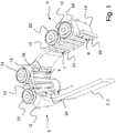
- the Fig. 1 shows a schematic perspective view of an embodiment of a drive 3 designed as a belt drive means 2 and a plurality of holding means 5 and 5 ', as they in various embodiments of a working module 1 according to the invention (cf. FIGS. 4 and 5 ) can be provided.
- the respective first wing 12 or 12 ' in this case forms a respective first fastening region 7, via which the respective first wing 12 or 12' is fixed to the belt 3.
- the respective second wing 14 or 14 ' forms a respective second fastening region 9 or 9', via which the respective second wing 14 or 14 'is secured to the belt 3.
- a respective first strip 24 or 24 ' is provided for the respective first fastening region 7 and 7', which is inserted into a toothing formed by the belt 3 and the belt 3 is clamped on the respective first wing 12 or 12 '. of the respective holding means 5 or 5 'sets.
- a respective second strip 26 or 26 ' is provided for the respective second fastening region 9 and 9', which is likewise inserted into a toothing formed by the belt 3 and the belt 3 is clamped to the respective second wing 14 or 14 'of the respective holding means 5 and 5 'sets.
- the strips 24, 24 ', 26 and 26' provided for the first fastening region 7 or 7 'and the second fastening region 9 and 9' lie flat against an inwardly directed side of the belt 3 in each case and put the belt 3 in a clamping manner respective holding means 5 and 5 'fixed.
- the respective strip 24, 24 ', 26 and 26' in each case extends at least approximately completely over an entire width of the belt 3.
- the first holding means 5 fastened to the belt 3 via the first fastening region 7 and the second fastening region 9 is located in an area in which the belt 5 is deflected.
- the second holding means 5 'fixed on the belt 3 via the first fastening region 7' and the second fastening region 9 ' are located in a region in which the drive means 2 or the belt 3 correspond Fig. 1 is moved in a linear direction.
- a synopsis of the first holding means 5 with the second holding means 5 'according to Fig. 1 illustrates here that the respective first wing 12 or 12 'can be pivoted with its respective first attachment region 7 or 7' relative to the respective second wing 14 or 14 'with its respective second attachment region 9 or 9'.
- the respective first wing 12 or 12 'and the respective second wing 14 or 14' pivotally connected to a common axis of rotation 13 or 13 'in connection.
- the respective holding means 5 or 5 'in the region of a deflection provided for the belt 3 can follow a curved direction of movement of the belt 3 and thereby from one for the second holding means 5' in FIG Fig. 1 shown orientation in the for the first holding means 5 in Fig. 1 shown orientation.
- the first holding means 5 comprises a first running and / or sliding roller 22 and a second running and / or sliding roller 24.
- the first running and / or sliding roller 22 and the second running and / or sliding roller 24 are respectively from the first holding means. 5 from and protrude laterally beyond the belt 3 out.
- the first running and / or sliding roller 22 and the second running and / or sliding roller 24 of the first holding means 5 in the course of a caused via the at least one belt 3 linear movement of the first holding means 5 each with a in the FIGS. 4 and 5 formed as part of the working module 1 rail 30 or 30 ', in which it is a support 31 and 31', are in surface contact.
- Both the first running and / or sliding roller 22 and the second running and / or sliding roller 24 are in surface contact with a side or surface of the rail 30 or 30 'which faces in the downward direction.
- the rail 30 or 30 ' is thus at least during a surface contact with the first running and / or sliding roller 22 or 22' and the second running and / or sliding roller 24 or 24 'above the respective first run and / or Slide roller 22 or 22 'and above the respective second running and / or sliding roller 24 or 24' positioned.
- the rail 30 or 30 'therefore provides, at least for a region in which the belt 3 follows an at least approximately linear direction of movement, via the first running and / or sliding roller 22 or 22' and the second running and / or sliding roller 24 or 24 'a positive guidance for the drive means 2 and the belt 3 ready.
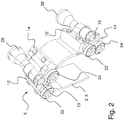
- the Fig. 2 shows a further schematic perspective view of the embodiment of a belt 3 and the holding means 5 and 5 'from Fig. 1 , Shown are also formed as part of the first holding means 5 first wing 12 and second wing 14 and the part of the second holding means 5 'formed first wing 12' and second wing 14 '.
- the leaves Fig. 2 now recognize about the respective holding means 5 and 5 'fixed to the belt 3 format part 28.
- the format part 28 is in Fig. 2 shown only in sections and in practice has an actual longitudinal extent along the axis of rotation 13, which over the in Fig. 2 shown longitudinal extent extends.
- the format part 28 or 28 'arranged on the respective holding means 5 or 5' can itself provide the respective common axis of rotation 13 around which the respective first fastening area 7 or 7 '(cf. Fig. 1 ) and the respective second fastening region 9 or 9 'are pivotable independently of one another.
- Articles or beverage containers can be pushed by means of several format parts 28 on a palletizer.
- the format parts 28 in this case come into surface contact with a plurality of articles of a respective palletizable layer on the back side and in this case push the respective palletizable layer onto a loading plate provided via the palletizer.
- Another format part 28 is provided, which is moved during the sliding without or at a short distance to leading articles or beverage containers of the respective palletizable layer and thereby prevents respective leading articles or beverage containers of a respective palettierstoryen position during the slide tilt unintentionally.
- the format part 28, which is fixed on the belt 3 via holding means 5 or 5 ' may also be formed by further format parts 28 which, with regard to the constructional structure and / or function, are of the kind shown in the figures of the present patent application Format part 28 differ.
- Format part 28 may be that groups of individual articles are formed by means of format parts 28, which are fastened to a respective belt 3 via holding means 5 or 5 '.
- format thermoplastic parts 28, which are fastened to a respective belt 3 via holding means 5 or 5 ' are used to apply planar thermoplastic packaging material to individual groups of articles.
- the Fig. 3 shows a schematic plan view of the embodiment of a belt 3 and the plurality of holding means 5 and 5 'from the FIGS. 1 and 2 ,
- Fig. 3 recognize again the course or the orientation of the axis of rotation 13 around which the first wing 12 and the second wing 14 of the first holding means 5 can be pivoted.
- the axis of rotation 13 extends through the format part 28, which is fixed on the holding means 5 on the belt 3.
- FIGS. 1 and 2 yet to be recognized belt 3 is in Fig. 3 hidden by the holding means 5 and 5 '.
- Fig. 3 illustrates here that the first running and / or sliding roller 22 and the second running and / or sliding roller 24 each laterally beyond the in Fig. 3 by the holding means 5 and 5 'concealed belt 3 protrude.
- the first running and / or sliding roller 22 'and in Fig. 3 not to be recognized second running and / or sliding roller 24 'of the second holding means 5' is provided that the first running and / or sliding roller 22 'and the second running and / or sliding roller 24' of the second holding means 5 'laterally over the in Fig. 3 by the holding means 5 and 5 'concealed belt 3 protrude.
- the holding means 5 comprises a first intermediate piece 11 and a second intermediate piece 11 ', via which first intermediate piece 11 and second intermediate piece 11' the format part 28 is held.
- the format part 8 is held in each case pivotally via the first intermediate piece 11 and the second intermediate piece 11, so that the format part 28 itself provides the common axis of rotation 13 or so that the format part 28 itself forms the common axis of rotation 13.
- the format part 28 is thus held by the first intermediate piece 11 and the second intermediate piece 11 'such that the first intermediate piece 11 and the second intermediate piece 11' are independent of each other about a common axis of rotation extending through the format part 28 and possibly formed by the format part 28 itself 13 are pivotable.
- the first running and / or sliding roller 22 is arranged at the first intermediate piece 11 .
- the second running and / or sliding roller 24 is arranged at the second intermediate piece 11 '.
- a first pivot axis 15 extends through the first idler and / or roller 22 arranged on the first intermediate piece 11.
- the wing 12, which forms the first attachment portion 7 and the intermediate piece 11 are rotatable relative to each other about the first pivot axis 15.
- a second pivot axis 15 ' extends through the second running and / or sliding roller 24.
- the second wing 14, which forms the second mounting portion 9 and the second intermediate piece 11' are rotatable relative to each other about the second pivot axis 15 '.
- the holding means 5 has a high degree of flexibility and can thus follow the movement and expansion of the belt 3 in the region of a deflection.
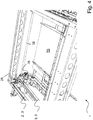
- the Fig. 4 shows a schematic perspective view of an embodiment of a working module according to the invention 1.
- the working module 1 comprises a first circulating belt 3, on which over holding means 5 (see. FIGS. 1 to 3 ) a plurality of format parts 28 are arranged.
- the working module 1 comprises a second revolving belt 3 ', on which further on holding means 5 (see. FIGS. 1 to 3 ) a plurality of format parts 28 are arranged.
- the format parts 28 are not completely shown in the figures of this patent application.
- a further first circumferentially moving belt and a further second revolving belt are provided, which in Fig. 4 are not visible and are arranged on an opposite side of the transport area TB.
- driver shaft 32 Shown is also a driver shaft 32, which drives on opposite sides of the transport region TB belt coupled to each other.
- the over holding means 5 (see. FIGS. 1 to 3 ) on the first belt 3 fixed format parts 28 come into contact with articles of a respective palletizable layer back and thereby pushing the respective palettierShe position of articles on the transport area TB.
- the format parts 28 arranged on the second belt 3 ' are hereby moved with no or slight distance to the foremost articles of the respective palletizable layer together with the respective palletizable layer over the transport region TB and in this case prevent the respective foremost articles of a respective palletizable layer from being pushed tilt unintentionally.
- the Fig. 5 shows a schematic perspective view with individual details of the embodiment of a working module 1 according to Fig. 4 ,
- the first belt shown by reference numeral 3 is driven by the drive pulley 36. Further, a guide roller 37 is provided, which is in contact with the belt 3.
- a format part 28 communicating with the first belt 3 via a holding means 5 and a format part 28 communicating with the second belt 3 'via a holding means can be seen.
- a respective holding means 5 or 5 ' has a first running and / or sliding roller 22 or 22' as well as a second running and / or sliding roller 24 or 24.
- Fig. 5 now shows a first trained as a support 31 rail 30 which is associated with the first belt 3.
- Fig. 5 a second rail 30 'which is also formed as a second support 31' and the second belt 3 ' assigned.
- Running and / or sliding rollers 22, 22 'and 24 and 24' which are formed as part of fixed to the first belt 3 holding means 5 and 5 'are associated with the first belt 3 associated rail 30 and with the The first belt 3 associated support 31 in surface contact and are guided over the first belt 3 associated rail 30 and the first belt 3 associated with the support 31.
- Running and / or sliding rollers 22, 22 'and 24 and 24' which are formed as part of the second belt 3 fixed holding means 5 and 5 ', with the second belt 3 associated rail 30' and with the the second belt associated support 31 'in surface contact and are guided over the said second belt 3' associated rail 30 'and on the second belt 3' associated support 31 '. In this way, an unwanted torsion of the first belt 3 and the second belt 3 'can be counteracted.
- a respective guide 35 or 35 ' is provided in this region, which is in surface contact with the respective belt 3 or 3' ,
Landscapes
- Engineering & Computer Science (AREA)
- Mechanical Engineering (AREA)
- Structure Of Belt Conveyors (AREA)
Applications Claiming Priority (1)
| Application Number | Priority Date | Filing Date | Title |
|---|---|---|---|
| DE102018108395.5A DE102018108395A1 (de) | 2018-04-10 | 2018-04-10 | Arbeitsmodul für eine Verpackungsvorrichtung und Verfahren zum Umgang mit Artikeln und/oder Verpackungsmaterial |
Publications (3)
| Publication Number | Publication Date |
|---|---|
| EP3552995A2 true EP3552995A2 (fr) | 2019-10-16 |
| EP3552995A3 EP3552995A3 (fr) | 2019-11-20 |
| EP3552995B1 EP3552995B1 (fr) | 2022-04-06 |
Family
ID=64901358
Family Applications (1)
| Application Number | Title | Priority Date | Filing Date |
|---|---|---|---|
| EP18215275.1A Active EP3552995B1 (fr) | 2018-04-10 | 2018-12-21 | Module de travail pour un dispositif d'emballage et procédé de manipulation d'articles et / ou de matériau d'emballage |
Country Status (3)
| Country | Link |
|---|---|
| EP (1) | EP3552995B1 (fr) |
| CN (1) | CN209720045U (fr) |
| DE (1) | DE102018108395A1 (fr) |
Cited By (1)
| Publication number | Priority date | Publication date | Assignee | Title |
|---|---|---|---|---|
| EP4686674A1 (fr) * | 2024-07-29 | 2026-02-04 | OCME S.r.l. | Dispositif de cloisonnement |
Family Cites Families (13)
| Publication number | Priority date | Publication date | Assignee | Title |
|---|---|---|---|---|
| DE2548613C3 (de) * | 1975-10-30 | 1982-02-11 | Kronseder, Hermann, 8404 Wörth | Fördervorrichtung für aufrechtstehende Gefäße |
| JPS59120711U (ja) * | 1983-01-31 | 1984-08-14 | 株式会社寺岡精工 | 搬送装置 |
| DE3422026A1 (de) * | 1984-06-14 | 1985-12-19 | Erich Rietzler KG Maschinenbau, 7080 Aalen | Vorrichtung zum ein- bzw. auspacken von flaschen, dosen od. dgl. |
| DE8912219U1 (de) * | 1989-10-13 | 1989-11-23 | Albert Handtmann Maschinenfabrik GmbH & Co KG, 7950 Biberach | Vorrichtung zum Transport von in einer zusammenhängenden Wursthülle eingefüllten Würsten |
| JP3142809B2 (ja) * | 1997-12-26 | 2001-03-07 | 株式会社寺岡精工 | 包装機 |
| IT1299951B1 (it) * | 1998-04-03 | 2000-04-04 | Ima Spa | Trasportatore per la movimentazione e contenitori tra stazioni operative. |
| DE19944780A1 (de) * | 1999-09-17 | 2001-04-19 | Focke & Co | Vorrichtung zum Transport von Gegenständen, insbesondere Zigarettengruppen |
| DE102004032735A1 (de) * | 2004-07-07 | 2006-02-09 | Robert Bosch Gmbh | Transportvorrichtung |
| DE102010063741A1 (de) * | 2010-12-21 | 2012-06-21 | Robert Bosch Gmbh | Transporteinrichtung |
| DE102012012204A1 (de) * | 2012-06-21 | 2013-12-24 | Focke & Co. (Gmbh & Co. Kg) | Taschenförderer zum Fördern von Zigarettengruppen |
| EP2886473B1 (fr) * | 2013-12-23 | 2016-10-19 | Tetra Laval Holdings & Finance S.A. | Unité d'alimentation et procédé d'alimentation de paquets scellés de produits alimentaires pouvant être versés |
| EP3064440B1 (fr) * | 2015-03-02 | 2017-09-13 | Tetra Laval Holdings & Finance S.A. | Unité d'enroulement de produit pour une ligne d'emballage |
| ITUB20159738A1 (it) * | 2015-12-18 | 2017-06-18 | Multipack Srl | Struttura di traslatore a sponde |
-
2018
- 2018-04-10 DE DE102018108395.5A patent/DE102018108395A1/de not_active Withdrawn
- 2018-12-21 EP EP18215275.1A patent/EP3552995B1/fr active Active
-
2019
- 2019-01-23 CN CN201920110756.XU patent/CN209720045U/zh active Active
Non-Patent Citations (1)
| Title |
|---|
| None |
Cited By (1)
| Publication number | Priority date | Publication date | Assignee | Title |
|---|---|---|---|---|
| EP4686674A1 (fr) * | 2024-07-29 | 2026-02-04 | OCME S.r.l. | Dispositif de cloisonnement |
Also Published As
| Publication number | Publication date |
|---|---|
| DE102018108395A1 (de) | 2019-10-10 |
| EP3552995A3 (fr) | 2019-11-20 |
| CN209720045U (zh) | 2019-12-03 |
| EP3552995B1 (fr) | 2022-04-06 |
Similar Documents
| Publication | Publication Date | Title |
|---|---|---|
| EP1170238B1 (fr) | Dispositif de retournement | |
| CH650729A5 (de) | Einrichtung fuer den transport und fuer das zusammenheften einer gruppe von schriftstuecken. | |
| CH624075A5 (fr) | ||
| DE4100477A1 (de) | Vorrichtung zur behandlung von gegenstaenden | |
| DE3144449A1 (de) | Vorrichtung zum gruppieren von gegenstaenden, insbesondere aufrechtstehende flaschen | |
| EP3381842B1 (fr) | Dispositif de transport destiné à réunir des marchandises au détail provenant de plusieurs convoyeurs d'introduction | |
| EP0457286A1 (fr) | Porte coulissante | |
| DE9215186U1 (de) | Transportvorrichtung für Gefäße | |
| DE69307255T2 (de) | Kammförmige Einheit zur Aufnahme von durch ein Förderband angeführten Produkten | |
| EP0110475B1 (fr) | Appareil radiologique muni d'un support à déplacement longitudinal | |
| EP3552995A2 (fr) | Module de travail pour un dispositif d'emballage et procédé de manipulation d'articles et / ou de matériau d'emballage | |
| EP0161412B1 (fr) | Dispositif de transport pour convoyer des montages supports de pièces | |
| DE2109468C2 (de) | Faltmaschine zum Umlegen der Laschen von Faltschachteln | |
| DE3039104A1 (de) | Foerderer, insbesondere fuer buchbindereiwerkstaetten | |
| DE19934361A1 (de) | Werkstück-Transfersystem | |
| DE2112372A1 (de) | Bearbeitungsvorrichtung fuer einzeln aufeinanderfolgende flache Gegenstaende | |
| EP1726552A1 (fr) | Dispositif d'assemblage de produits imprimés | |
| DE2816814C2 (de) | Vorrichtung zum Stapeln von elastischen, plattenförmigen oder flächigen Werkstücken | |
| DE3118512A1 (de) | Transportsystem mit einer foerderbahn fuer werkstuecke bzw. werkstuecktraeger | |
| WO2007048809A1 (fr) | Magasin a chaine | |
| DE4219091C2 (de) | Förderlinie | |
| DE2025667B2 (de) | Endloser Kettenförderer | |
| DE2652618C2 (de) | Vorrichtung zum Umsetzen eines Schuppenstromes aus Papierbogen | |
| EP0293324A2 (fr) | Dispositif d'empilage | |
| DE3404579C2 (de) | Vorrichtung zur Bearbeitung von Schaumstoffteilen, insbesondere von Hartschaumteilen |
Legal Events
| Date | Code | Title | Description |
|---|---|---|---|
| PUAI | Public reference made under article 153(3) epc to a published international application that has entered the european phase |
Free format text: ORIGINAL CODE: 0009012 |
|
| STAA | Information on the status of an ep patent application or granted ep patent |
Free format text: STATUS: THE APPLICATION HAS BEEN PUBLISHED |
|
| AK | Designated contracting states |
Kind code of ref document: A2 Designated state(s): AL AT BE BG CH CY CZ DE DK EE ES FI FR GB GR HR HU IE IS IT LI LT LU LV MC MK MT NL NO PL PT RO RS SE SI SK SM TR |
|
| AX | Request for extension of the european patent |
Extension state: BA ME |
|
| PUAL | Search report despatched |
Free format text: ORIGINAL CODE: 0009013 |
|
| AK | Designated contracting states |
Kind code of ref document: A3 Designated state(s): AL AT BE BG CH CY CZ DE DK EE ES FI FR GB GR HR HU IE IS IT LI LT LU LV MC MK MT NL NO PL PT RO RS SE SI SK SM TR |
|
| AX | Request for extension of the european patent |
Extension state: BA ME |
|
| RIC1 | Information provided on ipc code assigned before grant |
Ipc: B65B 21/06 20060101AFI20191016BHEP Ipc: B65G 19/24 20060101ALI20191016BHEP Ipc: B65B 21/24 20060101ALI20191016BHEP |
|
| STAA | Information on the status of an ep patent application or granted ep patent |
Free format text: STATUS: REQUEST FOR EXAMINATION WAS MADE |
|
| 17P | Request for examination filed |
Effective date: 20200326 |
|
| RBV | Designated contracting states (corrected) |
Designated state(s): AL AT BE BG CH CY CZ DE DK EE ES FI FR GB GR HR HU IE IS IT LI LT LU LV MC MK MT NL NO PL PT RO RS SE SI SK SM TR |
|
| REG | Reference to a national code |
Ref country code: DE Ref legal event code: R079 Ref document number: 502018009321 Country of ref document: DE Free format text: PREVIOUS MAIN CLASS: B65G0047260000 Ipc: B65B0035400000 |
|
| GRAP | Despatch of communication of intention to grant a patent |
Free format text: ORIGINAL CODE: EPIDOSNIGR1 |
|
| RIC1 | Information provided on ipc code assigned before grant |
Ipc: B65B 21/24 20060101ALI20211011BHEP Ipc: B65B 21/06 20060101ALI20211011BHEP Ipc: B65G 19/24 20060101ALI20211011BHEP Ipc: B65B 35/40 20060101AFI20211011BHEP |
|
| STAA | Information on the status of an ep patent application or granted ep patent |
Free format text: STATUS: GRANT OF PATENT IS INTENDED |
|
| INTG | Intention to grant announced |
Effective date: 20211118 |
|
| GRAS | Grant fee paid |
Free format text: ORIGINAL CODE: EPIDOSNIGR3 |
|
| GRAA | (expected) grant |
Free format text: ORIGINAL CODE: 0009210 |
|
| STAA | Information on the status of an ep patent application or granted ep patent |
Free format text: STATUS: THE PATENT HAS BEEN GRANTED |
|
| AK | Designated contracting states |
Kind code of ref document: B1 Designated state(s): AL AT BE BG CH CY CZ DE DK EE ES FI FR GB GR HR HU IE IS IT LI LT LU LV MC MK MT NL NO PL PT RO RS SE SI SK SM TR |
|
| REG | Reference to a national code |
Ref country code: GB Ref legal event code: FG4D Free format text: NOT ENGLISH |
|
| REG | Reference to a national code |
Ref country code: CH Ref legal event code: EP |
|
| REG | Reference to a national code |
Ref country code: AT Ref legal event code: REF Ref document number: 1481140 Country of ref document: AT Kind code of ref document: T Effective date: 20220415 |
|
| REG | Reference to a national code |
Ref country code: DE Ref legal event code: R096 Ref document number: 502018009321 Country of ref document: DE |
|
| REG | Reference to a national code |
Ref country code: IE Ref legal event code: FG4D Free format text: LANGUAGE OF EP DOCUMENT: GERMAN |
|
| REG | Reference to a national code |
Ref country code: LT Ref legal event code: MG9D |
|
| REG | Reference to a national code |
Ref country code: NL Ref legal event code: MP Effective date: 20220406 |
|
| PG25 | Lapsed in a contracting state [announced via postgrant information from national office to epo] |
Ref country code: NL Free format text: LAPSE BECAUSE OF FAILURE TO SUBMIT A TRANSLATION OF THE DESCRIPTION OR TO PAY THE FEE WITHIN THE PRESCRIBED TIME-LIMIT Effective date: 20220406 |
|
| PG25 | Lapsed in a contracting state [announced via postgrant information from national office to epo] |
Ref country code: SE Free format text: LAPSE BECAUSE OF FAILURE TO SUBMIT A TRANSLATION OF THE DESCRIPTION OR TO PAY THE FEE WITHIN THE PRESCRIBED TIME-LIMIT Effective date: 20220406 Ref country code: PT Free format text: LAPSE BECAUSE OF FAILURE TO SUBMIT A TRANSLATION OF THE DESCRIPTION OR TO PAY THE FEE WITHIN THE PRESCRIBED TIME-LIMIT Effective date: 20220808 Ref country code: NO Free format text: LAPSE BECAUSE OF FAILURE TO SUBMIT A TRANSLATION OF THE DESCRIPTION OR TO PAY THE FEE WITHIN THE PRESCRIBED TIME-LIMIT Effective date: 20220706 Ref country code: LT Free format text: LAPSE BECAUSE OF FAILURE TO SUBMIT A TRANSLATION OF THE DESCRIPTION OR TO PAY THE FEE WITHIN THE PRESCRIBED TIME-LIMIT Effective date: 20220406 Ref country code: HR Free format text: LAPSE BECAUSE OF FAILURE TO SUBMIT A TRANSLATION OF THE DESCRIPTION OR TO PAY THE FEE WITHIN THE PRESCRIBED TIME-LIMIT Effective date: 20220406 Ref country code: GR Free format text: LAPSE BECAUSE OF FAILURE TO SUBMIT A TRANSLATION OF THE DESCRIPTION OR TO PAY THE FEE WITHIN THE PRESCRIBED TIME-LIMIT Effective date: 20220707 Ref country code: FI Free format text: LAPSE BECAUSE OF FAILURE TO SUBMIT A TRANSLATION OF THE DESCRIPTION OR TO PAY THE FEE WITHIN THE PRESCRIBED TIME-LIMIT Effective date: 20220406 Ref country code: ES Free format text: LAPSE BECAUSE OF FAILURE TO SUBMIT A TRANSLATION OF THE DESCRIPTION OR TO PAY THE FEE WITHIN THE PRESCRIBED TIME-LIMIT Effective date: 20220406 Ref country code: BG Free format text: LAPSE BECAUSE OF FAILURE TO SUBMIT A TRANSLATION OF THE DESCRIPTION OR TO PAY THE FEE WITHIN THE PRESCRIBED TIME-LIMIT Effective date: 20220706 |
|
| PG25 | Lapsed in a contracting state [announced via postgrant information from national office to epo] |
Ref country code: RS Free format text: LAPSE BECAUSE OF FAILURE TO SUBMIT A TRANSLATION OF THE DESCRIPTION OR TO PAY THE FEE WITHIN THE PRESCRIBED TIME-LIMIT Effective date: 20220406 Ref country code: PL Free format text: LAPSE BECAUSE OF FAILURE TO SUBMIT A TRANSLATION OF THE DESCRIPTION OR TO PAY THE FEE WITHIN THE PRESCRIBED TIME-LIMIT Effective date: 20220406 Ref country code: LV Free format text: LAPSE BECAUSE OF FAILURE TO SUBMIT A TRANSLATION OF THE DESCRIPTION OR TO PAY THE FEE WITHIN THE PRESCRIBED TIME-LIMIT Effective date: 20220406 Ref country code: IS Free format text: LAPSE BECAUSE OF FAILURE TO SUBMIT A TRANSLATION OF THE DESCRIPTION OR TO PAY THE FEE WITHIN THE PRESCRIBED TIME-LIMIT Effective date: 20220806 |
|
| REG | Reference to a national code |
Ref country code: DE Ref legal event code: R097 Ref document number: 502018009321 Country of ref document: DE |
|
| PG25 | Lapsed in a contracting state [announced via postgrant information from national office to epo] |
Ref country code: SM Free format text: LAPSE BECAUSE OF FAILURE TO SUBMIT A TRANSLATION OF THE DESCRIPTION OR TO PAY THE FEE WITHIN THE PRESCRIBED TIME-LIMIT Effective date: 20220406 Ref country code: SK Free format text: LAPSE BECAUSE OF FAILURE TO SUBMIT A TRANSLATION OF THE DESCRIPTION OR TO PAY THE FEE WITHIN THE PRESCRIBED TIME-LIMIT Effective date: 20220406 Ref country code: RO Free format text: LAPSE BECAUSE OF FAILURE TO SUBMIT A TRANSLATION OF THE DESCRIPTION OR TO PAY THE FEE WITHIN THE PRESCRIBED TIME-LIMIT Effective date: 20220406 Ref country code: EE Free format text: LAPSE BECAUSE OF FAILURE TO SUBMIT A TRANSLATION OF THE DESCRIPTION OR TO PAY THE FEE WITHIN THE PRESCRIBED TIME-LIMIT Effective date: 20220406 Ref country code: DK Free format text: LAPSE BECAUSE OF FAILURE TO SUBMIT A TRANSLATION OF THE DESCRIPTION OR TO PAY THE FEE WITHIN THE PRESCRIBED TIME-LIMIT Effective date: 20220406 Ref country code: CZ Free format text: LAPSE BECAUSE OF FAILURE TO SUBMIT A TRANSLATION OF THE DESCRIPTION OR TO PAY THE FEE WITHIN THE PRESCRIBED TIME-LIMIT Effective date: 20220406 |
|
| PLBE | No opposition filed within time limit |
Free format text: ORIGINAL CODE: 0009261 |
|
| STAA | Information on the status of an ep patent application or granted ep patent |
Free format text: STATUS: NO OPPOSITION FILED WITHIN TIME LIMIT |
|
| 26N | No opposition filed |
Effective date: 20230110 |
|
| PG25 | Lapsed in a contracting state [announced via postgrant information from national office to epo] |
Ref country code: AL Free format text: LAPSE BECAUSE OF FAILURE TO SUBMIT A TRANSLATION OF THE DESCRIPTION OR TO PAY THE FEE WITHIN THE PRESCRIBED TIME-LIMIT Effective date: 20220406 |
|
| PG25 | Lapsed in a contracting state [announced via postgrant information from national office to epo] |
Ref country code: SI Free format text: LAPSE BECAUSE OF FAILURE TO SUBMIT A TRANSLATION OF THE DESCRIPTION OR TO PAY THE FEE WITHIN THE PRESCRIBED TIME-LIMIT Effective date: 20220406 |
|
| P01 | Opt-out of the competence of the unified patent court (upc) registered |
Effective date: 20230523 |
|
| REG | Reference to a national code |
Ref country code: CH Ref legal event code: PL |
|
| GBPC | Gb: european patent ceased through non-payment of renewal fee |
Effective date: 20221221 |
|
| REG | Reference to a national code |
Ref country code: BE Ref legal event code: MM Effective date: 20221231 |
|
| PG25 | Lapsed in a contracting state [announced via postgrant information from national office to epo] |
Ref country code: LU Free format text: LAPSE BECAUSE OF NON-PAYMENT OF DUE FEES Effective date: 20221221 |
|
| PG25 | Lapsed in a contracting state [announced via postgrant information from national office to epo] |
Ref country code: LI Free format text: LAPSE BECAUSE OF NON-PAYMENT OF DUE FEES Effective date: 20221231 Ref country code: IE Free format text: LAPSE BECAUSE OF NON-PAYMENT OF DUE FEES Effective date: 20221221 Ref country code: GB Free format text: LAPSE BECAUSE OF NON-PAYMENT OF DUE FEES Effective date: 20221221 Ref country code: CH Free format text: LAPSE BECAUSE OF NON-PAYMENT OF DUE FEES Effective date: 20221231 |
|
| PG25 | Lapsed in a contracting state [announced via postgrant information from national office to epo] |
Ref country code: BE Free format text: LAPSE BECAUSE OF NON-PAYMENT OF DUE FEES Effective date: 20221231 |
|
| PG25 | Lapsed in a contracting state [announced via postgrant information from national office to epo] |
Ref country code: HU Free format text: LAPSE BECAUSE OF FAILURE TO SUBMIT A TRANSLATION OF THE DESCRIPTION OR TO PAY THE FEE WITHIN THE PRESCRIBED TIME-LIMIT; INVALID AB INITIO Effective date: 20181221 |
|
| PG25 | Lapsed in a contracting state [announced via postgrant information from national office to epo] |
Ref country code: CY Free format text: LAPSE BECAUSE OF FAILURE TO SUBMIT A TRANSLATION OF THE DESCRIPTION OR TO PAY THE FEE WITHIN THE PRESCRIBED TIME-LIMIT Effective date: 20220406 |
|
| PG25 | Lapsed in a contracting state [announced via postgrant information from national office to epo] |
Ref country code: MK Free format text: LAPSE BECAUSE OF FAILURE TO SUBMIT A TRANSLATION OF THE DESCRIPTION OR TO PAY THE FEE WITHIN THE PRESCRIBED TIME-LIMIT Effective date: 20220406 |
|
| PG25 | Lapsed in a contracting state [announced via postgrant information from national office to epo] |
Ref country code: MC Free format text: LAPSE BECAUSE OF FAILURE TO SUBMIT A TRANSLATION OF THE DESCRIPTION OR TO PAY THE FEE WITHIN THE PRESCRIBED TIME-LIMIT Effective date: 20220406 |
|
| PG25 | Lapsed in a contracting state [announced via postgrant information from national office to epo] |
Ref country code: MC Free format text: LAPSE BECAUSE OF FAILURE TO SUBMIT A TRANSLATION OF THE DESCRIPTION OR TO PAY THE FEE WITHIN THE PRESCRIBED TIME-LIMIT Effective date: 20220406 |
|
| PG25 | Lapsed in a contracting state [announced via postgrant information from national office to epo] |
Ref country code: MT Free format text: LAPSE BECAUSE OF FAILURE TO SUBMIT A TRANSLATION OF THE DESCRIPTION OR TO PAY THE FEE WITHIN THE PRESCRIBED TIME-LIMIT Effective date: 20220406 |
|
| REG | Reference to a national code |
Ref country code: DE Ref legal event code: R082 Ref document number: 502018009321 Country of ref document: DE Representative=s name: BENNINGER, JOHANNES, DIPL.-ING., DE |
|
| PG25 | Lapsed in a contracting state [announced via postgrant information from national office to epo] |
Ref country code: BG Free format text: LAPSE BECAUSE OF FAILURE TO SUBMIT A TRANSLATION OF THE DESCRIPTION OR TO PAY THE FEE WITHIN THE PRESCRIBED TIME-LIMIT Effective date: 20220406 |
|
| PG25 | Lapsed in a contracting state [announced via postgrant information from national office to epo] |
Ref country code: BG Free format text: LAPSE BECAUSE OF FAILURE TO SUBMIT A TRANSLATION OF THE DESCRIPTION OR TO PAY THE FEE WITHIN THE PRESCRIBED TIME-LIMIT Effective date: 20220406 |
|
| PGFP | Annual fee paid to national office [announced via postgrant information from national office to epo] |
Ref country code: DE Payment date: 20241029 Year of fee payment: 7 |
|
| PGFP | Annual fee paid to national office [announced via postgrant information from national office to epo] |
Ref country code: FR Payment date: 20241111 Year of fee payment: 7 |
|
| PGFP | Annual fee paid to national office [announced via postgrant information from national office to epo] |
Ref country code: IT Payment date: 20241112 Year of fee payment: 7 |
|
| REG | Reference to a national code |
Ref country code: AT Ref legal event code: MM01 Ref document number: 1481140 Country of ref document: AT Kind code of ref document: T Effective date: 20231221 |
|
| PG25 | Lapsed in a contracting state [announced via postgrant information from national office to epo] |
Ref country code: AT Free format text: LAPSE BECAUSE OF NON-PAYMENT OF DUE FEES Effective date: 20231221 |
|
| PG25 | Lapsed in a contracting state [announced via postgrant information from national office to epo] |
Ref country code: TR Free format text: LAPSE BECAUSE OF FAILURE TO SUBMIT A TRANSLATION OF THE DESCRIPTION OR TO PAY THE FEE WITHIN THE PRESCRIBED TIME-LIMIT Effective date: 20220406 |
|
| PGFP | Annual fee paid to national office [announced via postgrant information from national office to epo] |
Ref country code: AT Payment date: 20260410 Year of fee payment: 5 |