EP3552995B1 - Module de travail pour un dispositif d'emballage et procédé de manipulation d'articles et / ou de matériau d'emballage - Google Patents
Module de travail pour un dispositif d'emballage et procédé de manipulation d'articles et / ou de matériau d'emballage Download PDFInfo
- Publication number
- EP3552995B1 EP3552995B1 EP18215275.1A EP18215275A EP3552995B1 EP 3552995 B1 EP3552995 B1 EP 3552995B1 EP 18215275 A EP18215275 A EP 18215275A EP 3552995 B1 EP3552995 B1 EP 3552995B1
- Authority
- EP
- European Patent Office
- Prior art keywords
- holding means
- belt
- running
- articles
- work module
- Prior art date
- Legal status (The legal status is an assumption and is not a legal conclusion. Google has not performed a legal analysis and makes no representation as to the accuracy of the status listed.)
- Active
Links
Images


Classifications
-
- B—PERFORMING OPERATIONS; TRANSPORTING
- B65—CONVEYING; PACKING; STORING; HANDLING THIN OR FILAMENTARY MATERIAL
- B65G—TRANSPORT OR STORAGE DEVICES, e.g. CONVEYORS FOR LOADING OR TIPPING, SHOP CONVEYOR SYSTEMS OR PNEUMATIC TUBE CONVEYORS
- B65G19/00—Conveyors comprising an impeller or a series of impellers carried by an endless traction element and arranged to move articles or materials over a supporting surface or underlying material, e.g. endless scraper conveyors
- B65G19/18—Details
- B65G19/22—Impellers, e.g. push-plates, scrapers; Guiding means therefor
- B65G19/24—Attachment of impellers to traction element
- B65G19/245—Attachment of impellers to traction element for article conveyors, e.g. for container conveyors
-
- B—PERFORMING OPERATIONS; TRANSPORTING
- B65—CONVEYING; PACKING; STORING; HANDLING THIN OR FILAMENTARY MATERIAL
- B65B—MACHINES, APPARATUS OR DEVICES FOR, OR METHODS OF, PACKAGING ARTICLES OR MATERIALS; UNPACKING
- B65B21/00—Packaging or unpacking of bottles
- B65B21/02—Packaging or unpacking of bottles in or from preformed containers, e.g. crates
- B65B21/04—Arranging, assembling, feeding, or orientating the bottles prior to introduction into, or after removal from, containers
- B65B21/06—Forming groups of bottles
-
- B—PERFORMING OPERATIONS; TRANSPORTING
- B65—CONVEYING; PACKING; STORING; HANDLING THIN OR FILAMENTARY MATERIAL
- B65B—MACHINES, APPARATUS OR DEVICES FOR, OR METHODS OF, PACKAGING ARTICLES OR MATERIALS; UNPACKING
- B65B21/00—Packaging or unpacking of bottles
- B65B21/24—Enclosing bottles in wrappers
- B65B21/245—Enclosing bottles in wrappers in flexible wrappers, e.g. foils
-
- B—PERFORMING OPERATIONS; TRANSPORTING
- B65—CONVEYING; PACKING; STORING; HANDLING THIN OR FILAMENTARY MATERIAL
- B65B—MACHINES, APPARATUS OR DEVICES FOR, OR METHODS OF, PACKAGING ARTICLES OR MATERIALS; UNPACKING
- B65B35/00—Supplying, feeding, arranging or orientating articles to be packaged
- B65B35/30—Arranging and feeding articles in groups
- B65B35/40—Arranging and feeding articles in groups by reciprocating or oscillatory pushers
- B65B35/405—Arranging and feeding articles in groups by reciprocating or oscillatory pushers linked to endless conveyors
Definitions
- the present invention relates to a working module for a packaging device and a method for handling articles and/or packaging material.
- packaging devices In order to provide the respective groups of articles with packaging material, packaging devices often have a large number of revolving or rotating wrapping rods, which apply flat packaging material, which may be made of shrink film or stretch film, to a respective group of articles.
- wrapping rods are arranged on conveyor chains for revolving or rotating movement.
- conveyor chains such as those used in packaging devices, for example, to move wrapping rods and/or dividing rods high acquisition costs and must be serviced or replaced at regular intervals. Since conveyor chains used in packaging devices consist of several individual links made of metal, each operation of such a packaging device is associated with an undesirably high volume.
- the EP 3 064 440 A1 discloses an apparatus which wraps products with a film.
- the device comprises support plates arranged on two opposite sides, with each support plate carrying a revolving chain.
- the chain is guided around a drive pulley and sprockets.
- the chain can also be formed by a belt.
- a bar is arranged on the chain by means of appropriate connecting means.
- a primary object of the invention can therefore be seen in particular as providing a practicable, cost-effective option that is easy to implement and by means of which the disadvantages mentioned are at least partially eliminated.
- the invention relates to a working module for a packaging device designed to handle articles and/or packaging material.
- the packaging device can have a number of individual modules, by means of which groups of articles are formed and/or by means of which packaging material is applied to articles and/or by means of which palletizable layers are transferred to an associated pallet.
- the working module can be embodied as such a module, which is a component of the packaging device.
- the working module comprises at least one revolving drive means.
- the work module also includes a number of format parts that are designed to act on articles and/or to handle packaging material.
- the working module also includes a number of holding means.
- the at least one revolving drive means comprises at least one revolving belt, to which at least one revolving belt the multiple format parts designed to act on articles and/or to handle packaging material are mechanically coupled via the multiple holding means.
- belts have lower acquisition costs and, compared to conveyor chains, are characterized by operation with a low noise level.
- the several holding means are each arranged via at least two fastening areas on at least one circumferentially guided belt, wherein the respective at least two fastening areas are positioned offset to one another with regard to the circumferential course of the at least one circumferentially guided belt.
- the at least two fastening areas can be positioned at a distance from one another on the at least one circumferentially guided belt.
- each of the at least two fastening areas is assigned a strip, which respective strip is inserted into a groove formed by a toothing of the at least one circumferentially guided belt and which respective strip clamps the respective holding means on at least one circumferential belt guided belt fixes.
- at least one screw connection can be provided for each strip, which at least one screw connection passes through the at least one circumferentially guided belt and thereby fixes the respective strip to a wing formed as part of the respective holding means.
- the plurality of holding means can also form their respective at least two fastening areas with a variable distance from one another.
- the plurality of holding means each have at least one axis of rotation about which the respective at least two fastening areas of a respective holding means can be pivoted independently of one another. By means of a pivoting movement, the plurality of holding means can thus, if necessary, change their distance from one another.
- the at least one belt Due to the circumferential guidance of the at least one belt, it may be the case that a portion of the at least one circumferentially guided belt located in the area of a deflection is temporarily stretched or is temporarily and reversibly elastically deformed.
- the at least two fastening areas of a respective holding means which may have a variable distance and are arranged on the section in the area of the deflection, can increase their relative distance and thereby follow the temporary elongation or the temporary reversible elastic deformation of the section.
- the section that was still stretched up to that point can contract or the section that has been reversibly elastically deformed up to that point can re-deform, with the at least two fastening areas of the respective holding means still fixed in the area of the section changing their relative distance to one another decrease or approach each other.
- the working module can have at least one deflection roller and/or at least one drive roller.
- the plurality of holding means each have a common axis of rotation for the respective at least two fastening areas, around which respective common axis of rotation the respective at least two fastening areas of a respective holding means can be pivoted independently of one another.
- the plurality of holding means each have a common axis of rotation for the respective at least two fastening areas, around which respective common axis of rotation the respective at least two fastening areas of a respective holding means can be pivoted independently of one another, with the respective at least two fastening areas being pivotable in the course of a respective pivoting movement about the common axis of rotation follow circular path.
- the at least two fastening areas can be pivoted about the respective common axis of rotation in the area of a respective deflection roller and/or drive roller.
- An axis of rotation of the deflection roller or the drive roller and the axis of rotation can be oriented parallel or substantially parallel to one another.
- the plurality of holding means form a respective first pivot axis for a respective first fastening area, about which the respective first fastening area can be rotated.
- the plurality of holding means form a respective second pivot axis for a respective second fastening region, about which respective second pivot axis the respective second fastening region can be rotated.
- the first pivot axis and the second pivot axis of a respective holding means are offset along the circumferential course of the respective at least one circumferentially guided belt and are preferably oriented parallel to one another.
- the several holding means each have a common one Axis of rotation for the respective at least two fastening areas, around which respective common axis of rotation the respective at least two fastening areas of a respective holding means can be pivoted independently of one another.
- the multiple holding means form a respective first pivot axis for a respective first fastening area, around which the respective first fastening area can be rotated
- the multiple holding means form a respective second pivot axis for a respective second fastening area, around which respective second pivot axis the respective second fastening area can be rotated.
- the first pivot axis, the second pivot axis and the common axis of rotation are offset along the circumferential course of the respective at least one circumferentially guided belt and are oriented parallel to one another.
- the common axis of rotation can be arranged between the first pivot axis and the second pivot axis.
- the plurality of holding means can also provide a respective attachment designed in particular as a receptacle for a respective format part, with the attachment designed in particular as a receptacle and the common axis of rotation being aligned with one another.
- the respective format part itself can form the common axis of rotation or provide the common axis of rotation.
- the working module can comprise at least one support, preferably designed as a rail. It can be provided that the at least one support, preferably designed as a rail, is positioned in such a way that the several holding means are in surface contact with the at least one support, preferably designed as a rail, during a substantially linear movement caused by the at least one belt.
- the several holding means each have at least one running and/or sliding roller protruding laterally from the respective holding means, via which at least one running and/or sliding roller protruding laterally from the respective holding means connects the respective holding means with the at least one preferably as Rail trained support is in surface contact.
- the several holding means each comprise at least a first running and/or sliding roller protruding laterally from the respective holding means and at least one second running and/or sliding roller protruding laterally from the respective holding means, with the several holding means having their first and second running and/or sliding rollers are in surface contact with the at least one support, which is preferably designed as a rail. Provision can be made here for the first running and/or sliding roller and the second running and/or sliding roller of a respective holding means to be pivotable independently of one another about the common axis of rotation of a respective holding means.
- the invention also relates to a method for handling articles and/or packaging material.
- a working module according to an embodiment of the preceding description is provided. It is further provided for the method according to the invention that the at least one revolving belt is moved in a rotating manner, as a result of which the multiple format parts act on the article and/or as a result the multiple format parts apply packaging material to the article.
- the working module according to the invention can be part of a drive means, which can be designed as a belt, for example.
- the working module can have several holding means.
- Each of these holding means can comprise a first wing and a second wing, respectively.
- the respective first wing here forms a first fastening area, via which the respective first wing is fixed to the belt.
- the second wing forms a second fastening area, via which the respective second wing is fixed to the belt.
- a first bar can be provided for the respective first fastening area, which is inserted into a toothing formed by the belt and clamps the belt to the respective first wing of the respective holding means.
- a second strip can be provided for the second fastening area, which is also inserted into a toothing formed by the belt and clamps the belt to the respective second wing of the respective holding means.
- the strips provided for the first attachment area and the second attachment area preferably lie flat on an inward-facing side of the belt and clamp the belt to the respective holding means.
- the respective strip extends at least approximately completely over the entire width of the belt.
- the first holding means attached to the belt via the first attachment area and the second attachment area is located in an area in which the belt is deflected.
- the one fixed on the belt via the first attachment area and the second attachment area is located second holding means in an area in which the drive means or the belt is moved in the linear direction.
- the first wing can be pivoted with its first attachment area in relation to the second wing with its second attachment area.
- the respective first wing and the respective second wing are pivotably connected to a common axis of rotation.
- the respective holding means can follow a curved direction of movement of the belt in the area of a deflection provided for the belt and can thereby move from an orientation of the second holding means to an orientation of the first holding means.
- the first holding means can comprise a first running and/or sliding roller and a second running and/or sliding roller.
- the first running and/or sliding roller and the second running and/or sliding roller each protrude from the first holding means and protrude laterally beyond the belt.
- the first running and/or sliding roller and the second running and/or sliding roller of the first holding means can each be connected to a rail, which is preferably designed as part of the working module, in the course of a linear movement of the first holding means caused by the at least one belt, in which it may be a support, are in surface contact.
- both the first running and/or sliding roller and the second running and/or sliding roller can each be in surface contact with a side or surface of the rail that faces downwards.
- the rail is thus positioned above the respective first running and/or sliding roller and above the respective second running and/or sliding roller at least during surface contact with the first running and/or sliding roller and the second running and/or sliding roller.
- Unintentional torsion of the belt can be counteracted by the surface contact between the first running and/or sliding roller and the second running and/or sliding roller and the rail.
- the rail therefore provides forced guidance for the drive means or the belt via the first running and/or sliding roller and the second running and/or sliding roller, at least for a region in which the belt follows an at least approximately linear direction of movement.
- a format part fixed on the belt via the respective holding means can be provided.
- the format part arranged on the holding means can itself provide a common axis of rotation about which the first Attachment area and the second attachment area are pivotable independently.
- articles or beverage containers can be pushed onto a palletizer using a number of format parts.
- the format parts come into surface contact with several articles of a respective layer that can be palletized on the back and push the respective layer that can be palletized onto a loading plate provided by the palletizer.
- Another format part can be provided, which is moved during pushing without or with a small distance to leading articles or beverage containers of the respective palletizable layer and thereby prevents the respective leading articles or beverage containers of a respective palletizable layer from tipping unintentionally during the pushing.
- the format part which is fixed to the belt by holding means, can also be formed by other format parts, which can differ from the format parts described here in terms of structural design and/or function. It can be the case, for example, that groups of individual articles are formed via format parts that are fixed to a respective belt via holding means. It can also be the case, for example, that flat thermoplastic packaging material is applied to individual groups of articles via format parts that are fixed to a respective belt via holding means.
- the axis of rotation mentioned runs through the format part, which is fixed to the belt via the holding means.
- the first running and/or sliding roller and the second running and/or sliding roller can each protrude laterally beyond the belt. It can also be provided for the first running and/or sliding roller and the second running and/or sliding roller of the second holding means that the first running and/or sliding roller and the second running and/or sliding roller of the second holding means are laterally above the straps protrude.
- the holding means can optionally comprise a first intermediate piece and a second intermediate piece which together hold the format part.
- the format part is held pivotably via the first intermediate piece and the second intermediate piece, so that the format part itself provides or forms the common axis of rotation.
- the format part is thus held by the first intermediate piece and the second intermediate piece in such a way that the first intermediate piece and the second Intermediate piece can be pivoted independently of one another about a common axis of rotation which runs through the format part and is possibly formed by the format part itself.
- the first running and/or sliding roller is arranged on the first intermediate piece.
- the second running and/or sliding roller is arranged on the second intermediate piece.
- the first running and/or sliding roller and the second running and/or sliding roller can be pivoted about the common axis of rotation together with the respective intermediate piece.
- the wing which forms the first fastening area, and the intermediate piece can be rotated or pivoted relative to one another about this first pivot axis.
- a second pivot axis also runs through the second running and/or sliding roller.
- the second wing which forms the second fastening area, and the second intermediate piece can thus preferably be rotated relative to one another about this second pivot axis. Due to the common axis of rotation formed by the first holding means, the first pivot axis 15 and the second pivot axis, the holding means has a high degree of flexibility and can thus follow the movement and stretching of the belt in the area of a deflection.
- the working module described here comprises a first revolving belt on which several format parts are arranged via holding means, which has already been explained in detail above.
- the working module can comprise a second revolving belt, on which a number of format parts can also be arranged via holding means.
- a further first circulating belt and a further second circulating belt can be provided, which can be arranged on an opposite side of the transport area.
- An optional drive shaft can drivingly couple belts arranged on opposite sides of the transport area to one another or to one another.
- the format parts fixed by holding means on the first belt come into contact with articles of a respective palletizable layer on the back and thereby push the respective palletizable layer of articles over the transport area.
- the format parts arranged on the second belt are moved over the transport area together with the respective palletizable layer with little or no distance to the foremost articles of the respective palletizable layer and prevent the unintentionally tilt the respective foremost article of a respective palletizable layer during pushing.
- the belt can be driven, for example, via a drive roller.
- the belt can also be guided over a deflection roller.
- a respective holding means has a first running and/or sliding roller and a second running and/or sliding roller.
- a first rail formed as a brace may be associated with the first strap.
- a second rail, also configured as a second support, may be associated with the second strap.
- running and/or sliding rollers which are designed as part of holding means fixed to the first belt, can be in surface contact with the rail or support associated with the first belt and are thereby assigned rail or guided over the support assigned to the first belt.
- Running and/or sliding rollers, which are designed as part of holding means fixed to the second belt, are in surface contact with the rail associated with the second belt or with the support associated with the second belt and are moved via the rail associated with the second belt or via guided the support associated with the second belt.
- a guide can be provided in this area which is in surface contact with the respective belt.
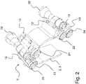
- the 1 shows a schematic perspective view of an embodiment of a belt 3 designed as a drive means 2 and a plurality of holding means 5 and 5 ', as shown in FIG in various embodiments of a work module 1 according to the invention (cf. figures 4 and 5 ) can be provided.
- the second holding means 5' shown each comprise a first wing 12 or 12' and a second wing 14 or 14'.
- the respective first wing 12 or 12 ′ forms a respective first attachment area 7 , via which the respective first wing 12 or 12 ′ is fixed to the belt 3 .
- the respective second wing 14 or 14 ′ forms a respective second fastening area 9 or 9 ′, via which the respective second wing 14 or 14 ′ is fixed to the belt 3 .
- a respective first strip 24 or 24' is provided for the respective first fastening region 7 or 7', which is inserted into a toothing formed by the belt 3 and clamps the belt 3 on the respective first wing 12 or 12'. of the respective holding means 5 or 5'.
- a respective second strip 26 or 26' is provided for the respective second fastening area 9 or 9', which is also inserted into a toothing formed by the belt 3 and clamps the belt 3 on the respective second wing 14 or 14' of the respective holding means 5 or 5'.
- the strips 24, 24', 26 and 26' provided for the first attachment area 7 or 7' and the second attachment area 9 or 9' each lie flat on an inward-facing side of the belt 3 and clamp the belt 3 on respective holding means 5 or 5'.
- the respective strip 24, 24', 26 and 26' extends at least approximately completely over the entire width of the belt 3.
- the first holding means 5 attached to the belt 3 via the first attachment area 7 and the second attachment area 9 is located in an area in which the belt 5 is deflected.
- the second holding means 5' fixed to the belt 3 via the first fastening area 7' and the second fastening area 9' is located in an area in which the drive means 2 and the belt 3 respectively 1 is moved in a linear direction.
- a synopsis of the first holding means 5 with the second holding means 5 'after 1 clarifies here that the respective first wing 12 or 12' with its respective first attachment area 7 or 7' can be pivoted relative to the respective second wing 14 or 14' with its respective second attachment area 9 or 9'.
- the respective first wing 12 or 12' and the respective second wing 14 or 14' are pivotably connected to a common axis of rotation 13 or 13'.
- the respective holding means 5 or 5' can follow a curved direction of movement of the belt 3 in the area of a deflection provided for the belt 3, and as a result from a direction for the second holding means 5' in 1 shown orientation in the for the first holding means 5 in 1 get the orientation shown.
- the first holding means 5 comprises a first running and/or sliding roller 22 and a second running and/or sliding roller 24.
- the first running and/or sliding roller 22 and the second running and/or sliding roller 24 each stand away from the first holding means 5 and protrude laterally beyond the belt 3.
- the first running and/or sliding roller 22 and the second running and/or sliding roller 24 of the first holding means 5 in the course of a linear movement of the first holding means 5 caused by the at least one belt 3 can each have a figures 4 and 5 are in surface contact with a rail 30 or 30', which is designed as part of the working module 1 and is a support 31 or 31'.
- both the first running and/or sliding roller 22 and the second running and/or sliding roller 24 are each in surface contact with a downward-facing side or surface of the rail 30 or 30'.
- the rail 30 or 30' is thus at least during surface contact with the first running and/or sliding roller 22 or 22' and the second running and/or sliding roller 24 or 24' above the respective first running and/or Sliding roller 22 or 22 'and above the respective second running and / or sliding roller 24 or 24' positioned.
- the surface contact between the first running and/or sliding roller 22 or 22' and the second running and/or sliding roller 24 or 24' and the rail 30 or 30' can counteract unwanted torsion of the belt 3.
- the rail 30 or 30' therefore provides, at least for a region in which the belt 3 follows an at least approximately linear direction of movement, via the first running and/or sliding roller 22 or 22' and the second running and/or sliding roller 24 and 24' provide a restricted guidance for the drive means 2 and the belt 3, respectively.
- the 2 Figure 1 shows a further schematic perspective view of the embodiment of a strap 3 and the holding means 5 and 5' 1 . Also shown are the first wing 12 and second wing 14 embodied as part of the first holding means 5 and the first wing 12 ′ and second wing 14 ′ formed as part of the second holding means 5 ′.
- Format part 28 is in 2 shown only in sections and in practice has an actual longitudinal extent along the axis of rotation 13, which extends beyond the 2 shown extends beyond.
- the format part 28 or 28' arranged on the respective holding means 5 or 5' can itself provide the respective common axis of rotation 13 around which the respective first fastening area 7 or 7' (cf. 1 ) and the respective second fastening area 9 or 9' can be pivoted independently of one another.
- off 2 Articles or beverage containers can be pushed onto a palletizer by means of several format parts 28.
- the format parts 28 come into surface contact with several articles of a respective palletizable layer on the back and push the respective palletizable layer onto a loading plate provided via the palletizer.
- Another format part 28 is provided, which is moved during the shifting with or without a small distance to preceding articles or beverage containers of the respective palletizable layer and thereby prevents the respective preceding articles or beverage containers of a respective palletizable layer from tipping unintentionally during the pushing.
- the format part 28, which is fixed to the belt 3 via holding means 5 or 5' can also be formed by further format parts 28, which differ in terms of structural design and/or function from that shown in the figures of the present patent application Distinguish format part 28. It can be the case, for example, that groups of individual articles are formed via format parts 28, which are fixed to a respective belt 3 via holding means 5 or 5'. It can also be the case, for example, that flat thermoplastic packaging material is applied to individual groups of articles via format parts 28, which are fixed to a respective belt 3 via holding means 5 or 5'.
- the 3 1 shows a schematic top view of the embodiment of a belt 3 and the plurality of holding means 5 and 5' from FIGS figures 1 and 2 .
- the 3 1 shows a schematic top view of the embodiment of a belt 3 and the plurality of holding means 5 and 5' from FIGS figures 1 and 2 .
- the axis of rotation 13 runs through the format part 28 which is fixed to the belt 3 via the holding means 5 .
- the in the figures 1 and 2 belt 3 that can still be seen is in 3 covered by the holding means 5 and 5'.
- 3 clarifies here that the first running and/or sliding roller 22 and the second running and/or sliding roller 24 each move laterally over the in 3 straps 3 covered by the holding means 5 and 5' protrude.
- first running and/or sliding roller 22' and the in 3 Unrecognizable second running and / or sliding roller 24 'of the second holding means 5' is provided that the first running and / or sliding roller 22 'and the second running and / or sliding roller 24' of the second holding means 5 'laterally over the in 3 straps 3 covered by the holding means 5 and 5' protrude.
- the holding means 5 comprises a first intermediate piece 11 and a second intermediate piece 11', via which first intermediate piece 11 and second intermediate piece 11' the format part 28 is held.
- the format part 8 is held pivotably via the first intermediate piece 11 and the second intermediate piece 11 so that the format part 28 itself provides the common axis of rotation 13 or so that the format part 28 itself forms the common axis of rotation 13 .
- the format part 28 is held by the first intermediate piece 11 and the second intermediate piece 11' in such a way that the first intermediate piece 11 and the second intermediate piece 11' independently of one another about a common axis of rotation that runs through the format part 28 and is possibly formed by the format part 28 itself 13 are pivotable.
- the first running and/or sliding roller 22 is arranged on the first intermediate piece 11 .
- the second running and/or sliding roller 24 is arranged on the second intermediate piece 11'.
- the first running and/or sliding roller 22 and the second running and/or sliding roller 24 can be pivoted about the common axis of rotation 13 together with the respective intermediate piece 11 or 11′.
- FIG. 12 further shows that a first pivot axis 15 runs through the first running and/or sliding roller 22 arranged on the first intermediate piece 11 .
- the wing 12, which forms the first fastening area 7, and the intermediate piece 11 can be rotated about the first pivot axis 15 relative to one another.
- a second pivot axis 15′ also runs through the second running and/or sliding roller 24.
- the second wing 14, which forms the second fastening area 9, and the second intermediate piece 11′ can be rotated relative to one another about the second pivot axis 15′.
- the holding means 5 Due to the common axis of rotation 13 formed by the first holding means 5, the first pivot axis 15 and the second pivot axis 15, the holding means 5 has a high degree of flexibility and can thus follow the movement and stretching of the belt 3 in the area of a deflection.
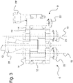
- the 4 shows a schematic perspective view of an embodiment of a work module 1 according to the invention.
- the work module 1 comprises a first revolving belt 3, to which holding means 5 (cf. Figures 1 to 3 ) several format parts 28 are arranged.
- the working module 1 comprises a second revolving belt 3', on which there are also holding means 5 (cf. Figures 1 to 3 ) several format parts 28 are arranged.
- the format parts 28 are not fully shown in the figures of the present patent application.
- a further first circulating belt and a further second circulating belt are provided, which in 4 cannot be seen and are arranged on an opposite side of the transport area TB.
- a driver shaft 32 is also shown, which couples belts arranged on opposite sides of the transport area TB to one another in terms of drive technology.
- the holding means 5 (cf. Figures 1 to 3 ) Format parts 28 fixed on the first belt 3 come into contact with articles from a respective palletizable layer on the back and thereby push the respective palletizable layer of articles over the transport area TB.
- the format parts 28 arranged on the second belt 3' are moved over the transport area TB together with the respective palletizable layer with little or no distance to the foremost articles of the respective palletizable layer and prevent the respective foremost articles of a respective palletizable layer from being pushed during the pushing unintentionally tilt.
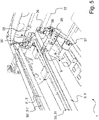
- the figure 5 1 shows a schematic perspective view with individual details of the embodiment of a working module 1 according to FIG 4 .
- the first belt shown for reference at number 3 is driven by the drive pulley 36 .
- a deflection roller 37 which is in contact with the belt 3 is also provided.
- figure 5 also shows a format part 28 connected to the first belt 3 via a holding means 5 and a format part 28 connected to the second belt 3' via a holding means.
- a respective holding means 5 or 5' has a first running and/or sliding roller 22 or 22' and a second running and/or sliding roller 24 or 24'.
- figure 5 FIG. 12 now shows a first rail 30 designed as a support 31, which is associated with the first belt 3.
- FIG. Next shows figure 5 a second rail 30', which is also designed as a second support 31' and the second strap 3' assigned.
- Running and / or sliding rollers 22, 22 'or 24 and 24' which are formed as part of the second belt 3 fixed holding means 5 or 5 'are formed with the second belt 3 associated rail 30' or with the in surface contact with the support 31' associated with the second belt and are guided over the rail 30' associated with the second belt 3' and over the support 31' associated with the second belt 3', respectively. This can counteract an unwanted torsion of the first belt 3 and the second belt 3'.
- a respective guide 35 or 35' is provided in this area, which is in surface contact with the respective belt 3 or 3' .
Landscapes
- Engineering & Computer Science (AREA)
- Mechanical Engineering (AREA)
- Structure Of Belt Conveyors (AREA)
Claims (8)
- Module de travail (1) conçu pour la manipulation d'articles et/ou de matériau d'emballage, pour un dispositif d'emballage, comprenant- au moins un moyen d'entraînement (2, 2') guidé en circulation,- une pluralité de pièces de format (28) qui sont conçues pour agir sur des articles et/ou pour manipuler du matériau d'emballage, ainsi qu'- une pluralité de moyens de maintien (5, 5'), dans lequel il est prévu que- ledit au moins un moyen d'entraînement (2, 2') guidé en circulation comprend au moins une courroie (3, 3') guidée en circulation; sur laquelle au moins une courroie (3, 3') guidée en circulation, la pluralité de pièces de format (28) conçues pour agir sur des articles et/ou pour manipuler du matériau d'emballage sont couplées de manière mécanique par l'intermédiaire de ladite pluralité de moyens de maintien (5, 5'), dans lequel la pluralité de moyens de maintien (5, 5') sont agencés chacun sur ladite au moins une courroie (3, 3') guidée en circulation, par au moins deux zones de fixation (7, 7', 9, 9'), dans lequel lesdites au moins deux zones de fixation (7, 7', 9, 9') respectives sont positionnées en étant décalées l'une par rapport à l'autre en vue du tracé circonférentiel de ladite au moins une courroie (3, 3') guidée en circulation, caractérisé par le fait que- la pluralité de moyens de maintien (5, 5') ont chacun un axe de rotation (13) commun pour lesdites au moins deux zones de fixation (7, 7', 9, 9') respectives; autour duquel axe de rotation (13) commun respectif, lesdites au moins deux zones de fixation (7, 7', 9, 9') respectives d'un moyen de maintien (5, 5') respectif peuvent pivoter indépendamment l'une de l'autre, et- que la pluralité de moyens de maintien (5, 5') forment un premier axe de pivotement (15) respectif pour une première zone de fixation (7, 7') respective, autour duquel la première zone de fixation (7, 7') respective peut être tournée, et dans lequel les plusieurs moyens de maintien (5, 5') forment un deuxième axe de pivotement (15') respectif pour une deuxième zone de fixation (9, 9') respective, c'est autour duquel deuxième axe de pivotement (15') respectif que ladite deuxième zone de fixation (9, 9') respective peut être tournée, dans lequel le premier axe de pivotement (15), le deuxième axe de pivotement (15') et l'axe de rotation (13) commun sont décalés les uns par rapport aux autres et orientés parallèlement les uns aux autres le long du tracé circonférentiel de ladite au moins une courroie (3, 3') respective guidée en circulation.
- Module de travail selon la revendication 1, dans lequel à chacune desdites au moins deux zones de fixation (7, 7', 9, 9') est associée une baguette (24, 24', 26, 26'), laquelle baguette (24, 24', 26, 26') respective est insérée dans une rainure formée par une denture de ladite au moins une courroie (3, 3') guidée en circulation, et laquelle baguette (24, 24', 26, 26') respective immobilise par serrage le moyen de maintien (5, 5') respectif sur ladite au moins une courroie (3, 3') guidée en circulation.
- Module de travail selon la revendication 1 ou la revendication 2, dans lequel la pluralité de moyens de maintien (5, 5') forment leurs au moins deux zones de fixation (7, 7', 9, 9') respectives à distance variable les unes par rapport aux autres.
- Module de travail selon la revendication 1, dans lequel la pluralité de moyens de maintien (5, 5') fournissent une fixation respective conçue en particulier en tant que logement pour une pièce de format (28) respective, dans lequel ladite fixation conçue en particulier en tant que logement et l'axe de rotation (13) commun sont orientés en étant alignés l'un sur l'autre.
- Module de travail selon l'une quelconque des revendications précédentes, comprenant au moins un support (31, 31') conçu de préférence en tant que rail (30, 30'), dans lequel ledit au moins un support (31, 31') conçu de préférence en tant que rail (30, 30') est positionné de telle manière que la pluralité de moyens de maintien (5, 5') sont en contact de surface avec ledit au moins un support (31, 31') conçu de préférence en tant que rail (30, 30'), au cours d'un mouvement pour l'essentiel linéaire provoqué par ladite au moins une courroie (3, 3') guidée en circulation.
- Module de travail selon la revendication 5, dans lequel la pluralité de moyens de maintien (5, 5') comprennent chacun au moins un galet de roulement et/ou de glissement (22, 22', 24, 24') qui fait saillie latéralement du moyen de maintien (5, 5') respectif, c'est par l'intermédiaire duquel au moins un galet de roulement et/ou de glissement (22, 22', 24, 24') faisant saillie latéralement du moyen de maintien (5, 5') respectif que le moyen de maintien (5, 5') respectif est en contact de surface avec ledit au moins un support (31, 31') conçu de préférence en tant que rail (30, 30').
- Module de travail selon l'une quelconque des revendications 1 à 6, dans lequel la pluralité de moyens de maintien (5, 5) comprennent chacun au moins un premier galet de roulement et/ou de glissement (22, 22') faisant saillie latéralement du moyen de maintien (5, 5') respectif ainsi qu'au moins un deuxième galet de roulement et/ou de glissement (24, 24') faisant saillie latéralement du moyen de maintien (5, 5') respectif, dans lequel la pluralité de moyens de maintien (5, 5') sont en contact de surface, via leurs premier et deuxième galets de roulement et/ou de glissement (22, 22', 24, 24'), avec ledit au moins un support (31, 31') conçu de préférence en tant que rail (30, 30'), et dans lequel il est prévu que le premier galet de roulement et/ou de glissement (22, 22') et le deuxième galet de roulement et/ou de glissement (24, 24') d'un moyen de maintien (5, 5') respectif peuvent pivoter indépendamment les uns des autres autour de l'axe de rotation (13) commun d'un moyen de maintien (5, 5') respectif.
- Procédé de manipulation d'articles et/ou de matériau d'emballage, comprenant un module de travail (1) selon l'une quelconque des revendications 1 à 7 et dans lequel procédé il est prévu que ladite au moins une courroie (3, 3') guidée en circulation est déplacée en rotation, d'où résulte que les plusieurs pièces de formats (28) agissent sur des articles et/ou appliquent du matériau d'emballage sur des articles.
Applications Claiming Priority (1)
| Application Number | Priority Date | Filing Date | Title |
|---|---|---|---|
| DE102018108395.5A DE102018108395A1 (de) | 2018-04-10 | 2018-04-10 | Arbeitsmodul für eine Verpackungsvorrichtung und Verfahren zum Umgang mit Artikeln und/oder Verpackungsmaterial |
Publications (3)
| Publication Number | Publication Date |
|---|---|
| EP3552995A2 EP3552995A2 (fr) | 2019-10-16 |
| EP3552995A3 EP3552995A3 (fr) | 2019-11-20 |
| EP3552995B1 true EP3552995B1 (fr) | 2022-04-06 |
Family
ID=64901358
Family Applications (1)
| Application Number | Title | Priority Date | Filing Date |
|---|---|---|---|
| EP18215275.1A Active EP3552995B1 (fr) | 2018-04-10 | 2018-12-21 | Module de travail pour un dispositif d'emballage et procédé de manipulation d'articles et / ou de matériau d'emballage |
Country Status (3)
| Country | Link |
|---|---|
| EP (1) | EP3552995B1 (fr) |
| CN (1) | CN209720045U (fr) |
| DE (1) | DE102018108395A1 (fr) |
Families Citing this family (1)
| Publication number | Priority date | Publication date | Assignee | Title |
|---|---|---|---|---|
| EP4686674A1 (fr) * | 2024-07-29 | 2026-02-04 | OCME S.r.l. | Dispositif de cloisonnement |
Family Cites Families (13)
| Publication number | Priority date | Publication date | Assignee | Title |
|---|---|---|---|---|
| DE2548613C3 (de) * | 1975-10-30 | 1982-02-11 | Kronseder, Hermann, 8404 Wörth | Fördervorrichtung für aufrechtstehende Gefäße |
| JPS59120711U (ja) * | 1983-01-31 | 1984-08-14 | 株式会社寺岡精工 | 搬送装置 |
| DE3422026A1 (de) * | 1984-06-14 | 1985-12-19 | Erich Rietzler KG Maschinenbau, 7080 Aalen | Vorrichtung zum ein- bzw. auspacken von flaschen, dosen od. dgl. |
| DE8912219U1 (de) * | 1989-10-13 | 1989-11-23 | Albert Handtmann Maschinenfabrik GmbH & Co KG, 7950 Biberach | Vorrichtung zum Transport von in einer zusammenhängenden Wursthülle eingefüllten Würsten |
| JP3142809B2 (ja) * | 1997-12-26 | 2001-03-07 | 株式会社寺岡精工 | 包装機 |
| IT1299951B1 (it) * | 1998-04-03 | 2000-04-04 | Ima Spa | Trasportatore per la movimentazione e contenitori tra stazioni operative. |
| DE19944780A1 (de) * | 1999-09-17 | 2001-04-19 | Focke & Co | Vorrichtung zum Transport von Gegenständen, insbesondere Zigarettengruppen |
| DE102004032735A1 (de) * | 2004-07-07 | 2006-02-09 | Robert Bosch Gmbh | Transportvorrichtung |
| DE102010063741A1 (de) * | 2010-12-21 | 2012-06-21 | Robert Bosch Gmbh | Transporteinrichtung |
| DE102012012204A1 (de) * | 2012-06-21 | 2013-12-24 | Focke & Co. (Gmbh & Co. Kg) | Taschenförderer zum Fördern von Zigarettengruppen |
| EP2886473B1 (fr) * | 2013-12-23 | 2016-10-19 | Tetra Laval Holdings & Finance S.A. | Unité d'alimentation et procédé d'alimentation de paquets scellés de produits alimentaires pouvant être versés |
| EP3064440B1 (fr) * | 2015-03-02 | 2017-09-13 | Tetra Laval Holdings & Finance S.A. | Unité d'enroulement de produit pour une ligne d'emballage |
| ITUB20159738A1 (it) * | 2015-12-18 | 2017-06-18 | Multipack Srl | Struttura di traslatore a sponde |
-
2018
- 2018-04-10 DE DE102018108395.5A patent/DE102018108395A1/de not_active Withdrawn
- 2018-12-21 EP EP18215275.1A patent/EP3552995B1/fr active Active
-
2019
- 2019-01-23 CN CN201920110756.XU patent/CN209720045U/zh active Active
Also Published As
| Publication number | Publication date |
|---|---|
| EP3552995A2 (fr) | 2019-10-16 |
| DE102018108395A1 (de) | 2019-10-10 |
| EP3552995A3 (fr) | 2019-11-20 |
| CN209720045U (zh) | 2019-12-03 |
Similar Documents
| Publication | Publication Date | Title |
|---|---|---|
| DE2613744C2 (de) | Vorrichtung zum Aufbringen eines Trägerstreifens aus elastischem Kunststoff auf bereitstehende Behälter | |
| DE69506670T2 (de) | Förderanlage zum Erzeugen von Zwischenräumen | |
| EP2412650B1 (fr) | Dispositif de stockage pour récipients et procédé de stockage de récipients | |
| DE102017011880B4 (de) | Teleskopförderer | |
| DE2740807A1 (de) | Bandfoerderer | |
| EP0105954A1 (fr) | Transporteur à bande, appliqué en particulier aux dispositifs d'emballage | |
| EP0564901B1 (fr) | Dispositif d'avance pour tÔle | |
| DE19849331A1 (de) | Schraubenhaltegurt | |
| DE102014103711A1 (de) | Umlenkvorrichtung für Gegenstände und Verfahren zum Umlenken von Gegenständen | |
| DE9215186U1 (de) | Transportvorrichtung für Gefäße | |
| EP2314529B1 (fr) | Unité de transport dotée de chaînes à petits rouleaux de retenue | |
| DE2537268B2 (de) | Vorrichtung zum Entnehmen von Behältern aus Kästen | |
| EP3552995B1 (fr) | Module de travail pour un dispositif d'emballage et procédé de manipulation d'articles et / ou de matériau d'emballage | |
| EP0161412B1 (fr) | Dispositif de transport pour convoyer des montages supports de pièces | |
| CH670809A5 (fr) | ||
| DE2810518C2 (de) | Vorrichtung zum Fördern von zu bindenden Blattstapeln durch Arbeitsstationen | |
| DE2109468C2 (de) | Faltmaschine zum Umlegen der Laschen von Faltschachteln | |
| DE3113237A1 (de) | Kommissionier-foerderanlage mit in transportrichtung hintereinander angeordneten uebergabestationen | |
| DE102016121253A1 (de) | Vorrichtung zum Transportieren von Objekten und insbesondere von Verpackungen, Getränkekästen und dergleichen | |
| DE69411908T2 (de) | Vorrichtung zum verpacken in faltschachteln | |
| DE2832385C2 (de) | Vorrichtung zum Überführen einer Bahn aus thermoplastischem Kunststoff von einer die Bahn kontinuierlich abgebenden Zuführeinrichtung zu einer die Bahn schrittweise aufnehmenden Thermoformvorrichtung | |
| DE102013216180A1 (de) | Umlenkvorrichtung für eine Kette aus Spannkluppen mit Laufrollen zum Transport einer bewegten Materialbahn | |
| DE2112372A1 (de) | Bearbeitungsvorrichtung fuer einzeln aufeinanderfolgende flache Gegenstaende | |
| DE2018199B2 (de) | Vorrichtung zur kontinuierlichen herstellung von mit flexiblen folien kaschierten hartschaumplatten insbesondere auf polyurethanbasis | |
| EP0594090A1 (fr) | Dispositif de positionnement d'objets |
Legal Events
| Date | Code | Title | Description |
|---|---|---|---|
| PUAI | Public reference made under article 153(3) epc to a published international application that has entered the european phase |
Free format text: ORIGINAL CODE: 0009012 |
|
| STAA | Information on the status of an ep patent application or granted ep patent |
Free format text: STATUS: THE APPLICATION HAS BEEN PUBLISHED |
|
| AK | Designated contracting states |
Kind code of ref document: A2 Designated state(s): AL AT BE BG CH CY CZ DE DK EE ES FI FR GB GR HR HU IE IS IT LI LT LU LV MC MK MT NL NO PL PT RO RS SE SI SK SM TR |
|
| AX | Request for extension of the european patent |
Extension state: BA ME |
|
| PUAL | Search report despatched |
Free format text: ORIGINAL CODE: 0009013 |
|
| AK | Designated contracting states |
Kind code of ref document: A3 Designated state(s): AL AT BE BG CH CY CZ DE DK EE ES FI FR GB GR HR HU IE IS IT LI LT LU LV MC MK MT NL NO PL PT RO RS SE SI SK SM TR |
|
| AX | Request for extension of the european patent |
Extension state: BA ME |
|
| RIC1 | Information provided on ipc code assigned before grant |
Ipc: B65B 21/06 20060101AFI20191016BHEP Ipc: B65G 19/24 20060101ALI20191016BHEP Ipc: B65B 21/24 20060101ALI20191016BHEP |
|
| STAA | Information on the status of an ep patent application or granted ep patent |
Free format text: STATUS: REQUEST FOR EXAMINATION WAS MADE |
|
| 17P | Request for examination filed |
Effective date: 20200326 |
|
| RBV | Designated contracting states (corrected) |
Designated state(s): AL AT BE BG CH CY CZ DE DK EE ES FI FR GB GR HR HU IE IS IT LI LT LU LV MC MK MT NL NO PL PT RO RS SE SI SK SM TR |
|
| REG | Reference to a national code |
Ref country code: DE Ref legal event code: R079 Ref document number: 502018009321 Country of ref document: DE Free format text: PREVIOUS MAIN CLASS: B65G0047260000 Ipc: B65B0035400000 |
|
| GRAP | Despatch of communication of intention to grant a patent |
Free format text: ORIGINAL CODE: EPIDOSNIGR1 |
|
| RIC1 | Information provided on ipc code assigned before grant |
Ipc: B65B 21/24 20060101ALI20211011BHEP Ipc: B65B 21/06 20060101ALI20211011BHEP Ipc: B65G 19/24 20060101ALI20211011BHEP Ipc: B65B 35/40 20060101AFI20211011BHEP |
|
| STAA | Information on the status of an ep patent application or granted ep patent |
Free format text: STATUS: GRANT OF PATENT IS INTENDED |
|
| INTG | Intention to grant announced |
Effective date: 20211118 |
|
| GRAS | Grant fee paid |
Free format text: ORIGINAL CODE: EPIDOSNIGR3 |
|
| GRAA | (expected) grant |
Free format text: ORIGINAL CODE: 0009210 |
|
| STAA | Information on the status of an ep patent application or granted ep patent |
Free format text: STATUS: THE PATENT HAS BEEN GRANTED |
|
| AK | Designated contracting states |
Kind code of ref document: B1 Designated state(s): AL AT BE BG CH CY CZ DE DK EE ES FI FR GB GR HR HU IE IS IT LI LT LU LV MC MK MT NL NO PL PT RO RS SE SI SK SM TR |
|
| REG | Reference to a national code |
Ref country code: GB Ref legal event code: FG4D Free format text: NOT ENGLISH |
|
| REG | Reference to a national code |
Ref country code: CH Ref legal event code: EP |
|
| REG | Reference to a national code |
Ref country code: AT Ref legal event code: REF Ref document number: 1481140 Country of ref document: AT Kind code of ref document: T Effective date: 20220415 |
|
| REG | Reference to a national code |
Ref country code: DE Ref legal event code: R096 Ref document number: 502018009321 Country of ref document: DE |
|
| REG | Reference to a national code |
Ref country code: IE Ref legal event code: FG4D Free format text: LANGUAGE OF EP DOCUMENT: GERMAN |
|
| REG | Reference to a national code |
Ref country code: LT Ref legal event code: MG9D |
|
| REG | Reference to a national code |
Ref country code: NL Ref legal event code: MP Effective date: 20220406 |
|
| PG25 | Lapsed in a contracting state [announced via postgrant information from national office to epo] |
Ref country code: NL Free format text: LAPSE BECAUSE OF FAILURE TO SUBMIT A TRANSLATION OF THE DESCRIPTION OR TO PAY THE FEE WITHIN THE PRESCRIBED TIME-LIMIT Effective date: 20220406 |
|
| PG25 | Lapsed in a contracting state [announced via postgrant information from national office to epo] |
Ref country code: SE Free format text: LAPSE BECAUSE OF FAILURE TO SUBMIT A TRANSLATION OF THE DESCRIPTION OR TO PAY THE FEE WITHIN THE PRESCRIBED TIME-LIMIT Effective date: 20220406 Ref country code: PT Free format text: LAPSE BECAUSE OF FAILURE TO SUBMIT A TRANSLATION OF THE DESCRIPTION OR TO PAY THE FEE WITHIN THE PRESCRIBED TIME-LIMIT Effective date: 20220808 Ref country code: NO Free format text: LAPSE BECAUSE OF FAILURE TO SUBMIT A TRANSLATION OF THE DESCRIPTION OR TO PAY THE FEE WITHIN THE PRESCRIBED TIME-LIMIT Effective date: 20220706 Ref country code: LT Free format text: LAPSE BECAUSE OF FAILURE TO SUBMIT A TRANSLATION OF THE DESCRIPTION OR TO PAY THE FEE WITHIN THE PRESCRIBED TIME-LIMIT Effective date: 20220406 Ref country code: HR Free format text: LAPSE BECAUSE OF FAILURE TO SUBMIT A TRANSLATION OF THE DESCRIPTION OR TO PAY THE FEE WITHIN THE PRESCRIBED TIME-LIMIT Effective date: 20220406 Ref country code: GR Free format text: LAPSE BECAUSE OF FAILURE TO SUBMIT A TRANSLATION OF THE DESCRIPTION OR TO PAY THE FEE WITHIN THE PRESCRIBED TIME-LIMIT Effective date: 20220707 Ref country code: FI Free format text: LAPSE BECAUSE OF FAILURE TO SUBMIT A TRANSLATION OF THE DESCRIPTION OR TO PAY THE FEE WITHIN THE PRESCRIBED TIME-LIMIT Effective date: 20220406 Ref country code: ES Free format text: LAPSE BECAUSE OF FAILURE TO SUBMIT A TRANSLATION OF THE DESCRIPTION OR TO PAY THE FEE WITHIN THE PRESCRIBED TIME-LIMIT Effective date: 20220406 Ref country code: BG Free format text: LAPSE BECAUSE OF FAILURE TO SUBMIT A TRANSLATION OF THE DESCRIPTION OR TO PAY THE FEE WITHIN THE PRESCRIBED TIME-LIMIT Effective date: 20220706 |
|
| PG25 | Lapsed in a contracting state [announced via postgrant information from national office to epo] |
Ref country code: RS Free format text: LAPSE BECAUSE OF FAILURE TO SUBMIT A TRANSLATION OF THE DESCRIPTION OR TO PAY THE FEE WITHIN THE PRESCRIBED TIME-LIMIT Effective date: 20220406 Ref country code: PL Free format text: LAPSE BECAUSE OF FAILURE TO SUBMIT A TRANSLATION OF THE DESCRIPTION OR TO PAY THE FEE WITHIN THE PRESCRIBED TIME-LIMIT Effective date: 20220406 Ref country code: LV Free format text: LAPSE BECAUSE OF FAILURE TO SUBMIT A TRANSLATION OF THE DESCRIPTION OR TO PAY THE FEE WITHIN THE PRESCRIBED TIME-LIMIT Effective date: 20220406 Ref country code: IS Free format text: LAPSE BECAUSE OF FAILURE TO SUBMIT A TRANSLATION OF THE DESCRIPTION OR TO PAY THE FEE WITHIN THE PRESCRIBED TIME-LIMIT Effective date: 20220806 |
|
| REG | Reference to a national code |
Ref country code: DE Ref legal event code: R097 Ref document number: 502018009321 Country of ref document: DE |
|
| PG25 | Lapsed in a contracting state [announced via postgrant information from national office to epo] |
Ref country code: SM Free format text: LAPSE BECAUSE OF FAILURE TO SUBMIT A TRANSLATION OF THE DESCRIPTION OR TO PAY THE FEE WITHIN THE PRESCRIBED TIME-LIMIT Effective date: 20220406 Ref country code: SK Free format text: LAPSE BECAUSE OF FAILURE TO SUBMIT A TRANSLATION OF THE DESCRIPTION OR TO PAY THE FEE WITHIN THE PRESCRIBED TIME-LIMIT Effective date: 20220406 Ref country code: RO Free format text: LAPSE BECAUSE OF FAILURE TO SUBMIT A TRANSLATION OF THE DESCRIPTION OR TO PAY THE FEE WITHIN THE PRESCRIBED TIME-LIMIT Effective date: 20220406 Ref country code: EE Free format text: LAPSE BECAUSE OF FAILURE TO SUBMIT A TRANSLATION OF THE DESCRIPTION OR TO PAY THE FEE WITHIN THE PRESCRIBED TIME-LIMIT Effective date: 20220406 Ref country code: DK Free format text: LAPSE BECAUSE OF FAILURE TO SUBMIT A TRANSLATION OF THE DESCRIPTION OR TO PAY THE FEE WITHIN THE PRESCRIBED TIME-LIMIT Effective date: 20220406 Ref country code: CZ Free format text: LAPSE BECAUSE OF FAILURE TO SUBMIT A TRANSLATION OF THE DESCRIPTION OR TO PAY THE FEE WITHIN THE PRESCRIBED TIME-LIMIT Effective date: 20220406 |
|
| PLBE | No opposition filed within time limit |
Free format text: ORIGINAL CODE: 0009261 |
|
| STAA | Information on the status of an ep patent application or granted ep patent |
Free format text: STATUS: NO OPPOSITION FILED WITHIN TIME LIMIT |
|
| 26N | No opposition filed |
Effective date: 20230110 |
|
| PG25 | Lapsed in a contracting state [announced via postgrant information from national office to epo] |
Ref country code: AL Free format text: LAPSE BECAUSE OF FAILURE TO SUBMIT A TRANSLATION OF THE DESCRIPTION OR TO PAY THE FEE WITHIN THE PRESCRIBED TIME-LIMIT Effective date: 20220406 |
|
| PG25 | Lapsed in a contracting state [announced via postgrant information from national office to epo] |
Ref country code: SI Free format text: LAPSE BECAUSE OF FAILURE TO SUBMIT A TRANSLATION OF THE DESCRIPTION OR TO PAY THE FEE WITHIN THE PRESCRIBED TIME-LIMIT Effective date: 20220406 |
|
| P01 | Opt-out of the competence of the unified patent court (upc) registered |
Effective date: 20230523 |
|
| REG | Reference to a national code |
Ref country code: CH Ref legal event code: PL |
|
| GBPC | Gb: european patent ceased through non-payment of renewal fee |
Effective date: 20221221 |
|
| REG | Reference to a national code |
Ref country code: BE Ref legal event code: MM Effective date: 20221231 |
|
| PG25 | Lapsed in a contracting state [announced via postgrant information from national office to epo] |
Ref country code: LU Free format text: LAPSE BECAUSE OF NON-PAYMENT OF DUE FEES Effective date: 20221221 |
|
| PG25 | Lapsed in a contracting state [announced via postgrant information from national office to epo] |
Ref country code: LI Free format text: LAPSE BECAUSE OF NON-PAYMENT OF DUE FEES Effective date: 20221231 Ref country code: IE Free format text: LAPSE BECAUSE OF NON-PAYMENT OF DUE FEES Effective date: 20221221 Ref country code: GB Free format text: LAPSE BECAUSE OF NON-PAYMENT OF DUE FEES Effective date: 20221221 Ref country code: CH Free format text: LAPSE BECAUSE OF NON-PAYMENT OF DUE FEES Effective date: 20221231 |
|
| PG25 | Lapsed in a contracting state [announced via postgrant information from national office to epo] |
Ref country code: BE Free format text: LAPSE BECAUSE OF NON-PAYMENT OF DUE FEES Effective date: 20221231 |
|
| PG25 | Lapsed in a contracting state [announced via postgrant information from national office to epo] |
Ref country code: HU Free format text: LAPSE BECAUSE OF FAILURE TO SUBMIT A TRANSLATION OF THE DESCRIPTION OR TO PAY THE FEE WITHIN THE PRESCRIBED TIME-LIMIT; INVALID AB INITIO Effective date: 20181221 |
|
| PG25 | Lapsed in a contracting state [announced via postgrant information from national office to epo] |
Ref country code: CY Free format text: LAPSE BECAUSE OF FAILURE TO SUBMIT A TRANSLATION OF THE DESCRIPTION OR TO PAY THE FEE WITHIN THE PRESCRIBED TIME-LIMIT Effective date: 20220406 |
|
| PG25 | Lapsed in a contracting state [announced via postgrant information from national office to epo] |
Ref country code: MK Free format text: LAPSE BECAUSE OF FAILURE TO SUBMIT A TRANSLATION OF THE DESCRIPTION OR TO PAY THE FEE WITHIN THE PRESCRIBED TIME-LIMIT Effective date: 20220406 |
|
| PG25 | Lapsed in a contracting state [announced via postgrant information from national office to epo] |
Ref country code: MC Free format text: LAPSE BECAUSE OF FAILURE TO SUBMIT A TRANSLATION OF THE DESCRIPTION OR TO PAY THE FEE WITHIN THE PRESCRIBED TIME-LIMIT Effective date: 20220406 |
|
| PG25 | Lapsed in a contracting state [announced via postgrant information from national office to epo] |
Ref country code: MC Free format text: LAPSE BECAUSE OF FAILURE TO SUBMIT A TRANSLATION OF THE DESCRIPTION OR TO PAY THE FEE WITHIN THE PRESCRIBED TIME-LIMIT Effective date: 20220406 |
|
| PG25 | Lapsed in a contracting state [announced via postgrant information from national office to epo] |
Ref country code: MT Free format text: LAPSE BECAUSE OF FAILURE TO SUBMIT A TRANSLATION OF THE DESCRIPTION OR TO PAY THE FEE WITHIN THE PRESCRIBED TIME-LIMIT Effective date: 20220406 |
|
| REG | Reference to a national code |
Ref country code: DE Ref legal event code: R082 Ref document number: 502018009321 Country of ref document: DE Representative=s name: BENNINGER, JOHANNES, DIPL.-ING., DE |
|
| PG25 | Lapsed in a contracting state [announced via postgrant information from national office to epo] |
Ref country code: BG Free format text: LAPSE BECAUSE OF FAILURE TO SUBMIT A TRANSLATION OF THE DESCRIPTION OR TO PAY THE FEE WITHIN THE PRESCRIBED TIME-LIMIT Effective date: 20220406 |
|
| PG25 | Lapsed in a contracting state [announced via postgrant information from national office to epo] |
Ref country code: BG Free format text: LAPSE BECAUSE OF FAILURE TO SUBMIT A TRANSLATION OF THE DESCRIPTION OR TO PAY THE FEE WITHIN THE PRESCRIBED TIME-LIMIT Effective date: 20220406 |
|
| PGFP | Annual fee paid to national office [announced via postgrant information from national office to epo] |
Ref country code: DE Payment date: 20241029 Year of fee payment: 7 |
|
| PGFP | Annual fee paid to national office [announced via postgrant information from national office to epo] |
Ref country code: FR Payment date: 20241111 Year of fee payment: 7 |
|
| PGFP | Annual fee paid to national office [announced via postgrant information from national office to epo] |
Ref country code: IT Payment date: 20241112 Year of fee payment: 7 |
|
| REG | Reference to a national code |
Ref country code: AT Ref legal event code: MM01 Ref document number: 1481140 Country of ref document: AT Kind code of ref document: T Effective date: 20231221 |
|
| PG25 | Lapsed in a contracting state [announced via postgrant information from national office to epo] |
Ref country code: AT Free format text: LAPSE BECAUSE OF NON-PAYMENT OF DUE FEES Effective date: 20231221 |
|
| PG25 | Lapsed in a contracting state [announced via postgrant information from national office to epo] |
Ref country code: TR Free format text: LAPSE BECAUSE OF FAILURE TO SUBMIT A TRANSLATION OF THE DESCRIPTION OR TO PAY THE FEE WITHIN THE PRESCRIBED TIME-LIMIT Effective date: 20220406 |
|
| PGFP | Annual fee paid to national office [announced via postgrant information from national office to epo] |
Ref country code: AT Payment date: 20260410 Year of fee payment: 5 |