EP3552995A2 - Work module for a packaging device and method for handling items and/or packaging material - Google Patents
Work module for a packaging device and method for handling items and/or packaging material Download PDFInfo
- Publication number
- EP3552995A2 EP3552995A2 EP18215275.1A EP18215275A EP3552995A2 EP 3552995 A2 EP3552995 A2 EP 3552995A2 EP 18215275 A EP18215275 A EP 18215275A EP 3552995 A2 EP3552995 A2 EP 3552995A2
- Authority
- EP
- European Patent Office
- Prior art keywords
- holding means
- belt
- running
- articles
- rotation
- Prior art date
- Legal status (The legal status is an assumption and is not a legal conclusion. Google has not performed a legal analysis and makes no representation as to the accuracy of the status listed.)
- Granted
Links
Images


Classifications
-
- B—PERFORMING OPERATIONS; TRANSPORTING
- B65—CONVEYING; PACKING; STORING; HANDLING THIN OR FILAMENTARY MATERIAL
- B65G—TRANSPORT OR STORAGE DEVICES, e.g. CONVEYORS FOR LOADING OR TIPPING, SHOP CONVEYOR SYSTEMS OR PNEUMATIC TUBE CONVEYORS
- B65G19/00—Conveyors comprising an impeller or a series of impellers carried by an endless traction element and arranged to move articles or materials over a supporting surface or underlying material, e.g. endless scraper conveyors
- B65G19/18—Details
- B65G19/22—Impellers, e.g. push-plates, scrapers; Guiding means therefor
- B65G19/24—Attachment of impellers to traction element
- B65G19/245—Attachment of impellers to traction element for article conveyors, e.g. for container conveyors
-
- B—PERFORMING OPERATIONS; TRANSPORTING
- B65—CONVEYING; PACKING; STORING; HANDLING THIN OR FILAMENTARY MATERIAL
- B65B—MACHINES, APPARATUS OR DEVICES FOR, OR METHODS OF, PACKAGING ARTICLES OR MATERIALS; UNPACKING
- B65B21/00—Packaging or unpacking of bottles
- B65B21/02—Packaging or unpacking of bottles in or from preformed containers, e.g. crates
- B65B21/04—Arranging, assembling, feeding, or orientating the bottles prior to introduction into, or after removal from, containers
- B65B21/06—Forming groups of bottles
-
- B—PERFORMING OPERATIONS; TRANSPORTING
- B65—CONVEYING; PACKING; STORING; HANDLING THIN OR FILAMENTARY MATERIAL
- B65B—MACHINES, APPARATUS OR DEVICES FOR, OR METHODS OF, PACKAGING ARTICLES OR MATERIALS; UNPACKING
- B65B21/00—Packaging or unpacking of bottles
- B65B21/24—Enclosing bottles in wrappers
- B65B21/245—Enclosing bottles in wrappers in flexible wrappers, e.g. foils
-
- B—PERFORMING OPERATIONS; TRANSPORTING
- B65—CONVEYING; PACKING; STORING; HANDLING THIN OR FILAMENTARY MATERIAL
- B65B—MACHINES, APPARATUS OR DEVICES FOR, OR METHODS OF, PACKAGING ARTICLES OR MATERIALS; UNPACKING
- B65B35/00—Supplying, feeding, arranging or orientating articles to be packaged
- B65B35/30—Arranging and feeding articles in groups
- B65B35/40—Arranging and feeding articles in groups by reciprocating or oscillatory pushers
- B65B35/405—Arranging and feeding articles in groups by reciprocating or oscillatory pushers linked to endless conveyors
Definitions
- the present invention relates to a working module for a packaging device and a method for handling articles and / or packaging material.
- rows of articles are moved parallel to one another, whereby successive articles may be contiguous.
- a certain number of leading articles may be briefly accelerated compared to subsequent articles.
- one-piece rods may be provided, which come into contact with the specified number of articles on the back and then accelerate the articles of the specified number in relation to the subsequent articles for a short time.
- packaging devices in which by means of such Einteilstäbe subsequent articles are delayed against the leading articles for a short time.
- a relative spacing is formed between the particular number of leading articles and subsequent articles, thereby creating groups of articles to which packaging material may subsequently be applied.
- the dividing bars are arranged on continuously moving conveyor chains.
- the respective relative distance or pitch of arranged at the circumferentially moving conveyor chains Einteilstäben each other is here matched to the respective group of articles to be formed.
- packaging devices In order to provide the respective groups of articles with packaging material, packaging devices often have a multiplicity of revolving or turning impact bars, which apply flat and optionally shrink-wrapped or stretch-formed packaging material to a respective group of articles.
- impact bars are arranged in practice for circulating or rotating movement on conveyor chains.
- Circulating conveyor chains as used in packaging devices, for example, for the movement of impact bars and / or Einteilstäben use own high initial costs and must be serviced or replaced at regular intervals. Since conveyor chains used in packaging devices consist of several individual members formed of metal, a respective operation of such a packaging device is associated with an undesirably high volume.
- a primary object of the invention can therefore be seen in particular to provide a practicable, inexpensive to implement and cost-effective means by which the disadvantages mentioned are at least partially eliminated.
- the invention relates to a trained for handling articles and / or packaging material working module for a packaging device.
- the packaging device may have a plurality of individual modules by means of which groups of articles are formed and / or by means of which packaging material is applied to articles and / or by means of which palletizable layers are transferred to an associated pallet.
- the working module can be designed in conceivable embodiments as such a module which is part of the packaging device.
- the working module comprises at least one circulating drive means. Furthermore, the working module comprises a plurality of format parts which are designed to act on articles and / or for handling packaging material. Also, the working module comprises a plurality of holding means.
- the at least one circumferentially guided drive means comprises at least one circumferentially guided belt, to which at least one circulating guided belt, the plurality of formed for acting on articles and / or handling packaging material format parts are mechanically coupled via the plurality of holding means.
- belts have lower acquisition costs compared to conveyor chains and are distinguished from conveyor chains by low-noise operation.
- the plurality of holding means in each case arranged on at least two attachment regions on at least one circulating guided belt are, wherein the respective at least two mounting portion are positioned offset from each other with respect to the circumferential course of the at least one circumferentially guided belt.
- the at least two attachment regions can be positioned spaced apart from each other on at least one circumferentially guided belt.
- each of the at least two attachment areas is assigned a bar, which respective bar is inserted into a formed by a toothing of at least one circumferentially guided belt groove and which respective bar clamping the respective holding means on at least one circumferential fixed belt.
- at least one screw connection can be provided for each strip, which passes through at least one screw the at least one circumferentially guided belt and in this case fixes the respective strip on a formed as part of the respective holding means wing.
- the plurality of holding means may form their respective at least two attachment regions spaced from one another.
- the plurality of holding means each have at least one axis of rotation about which the respective at least two attachment areas of a respective holding means are pivotable independently of one another have proved successful. By means of a pivoting movement, the plurality of holding means can thus possibly change their distance from one another.
- the at least one belt Due to the circumferential guidance of the at least one belt, it may be that a portion of the at least one circulating belt located in the region of a deflection is temporarily stretched or is temporarily reversibly elastically deformed.
- the possibly space-variable and arranged at the located in the region of the deflection lot arranged at least two mounting portions of a respective holding means can increase their relative distance and in this case the temporary stretching or the temporary reversible elastic deformation of the lot follow.
- the previously stretched portion may contract or deform the previously reversibly elastically deformed portion, wherein the at least two fixing areas of the respective holding means which are still fixed in the area of the portion maintain their relative distance from each other zoom out or approach each other.
- the working module can have at least one deflection roller and / or at least one drive roller.
- the plurality of holding means each have a common axis of rotation for the respective at least two mounting areas about which respective common axis of rotation the respective at least two mounting portion of a respective holding means are independently pivotable.
- the plurality of holding means each have a common axis of rotation for the respective at least two mounting portion about which respective common axis of rotation the respective at least two mounting portion of a respective holding means are independently pivotable, wherein the respective at least two mounting portions in the course of a respective pivoting movement to follow the common axis of rotation of a circular path.
- the at least two attachment regions can be pivoted about the respective common axis of rotation in the region of a respective deflection roller and / or drive roller.
- An axis of rotation of the deflection roller or of the drive roller and the axis of rotation can be oriented parallel or substantially parallel to one another.
- the plurality of holding means for each respective first attachment area may form a respective first pivot axis about which the respective first attachment area can be rotated.
- the plurality of holding means for a respective second attachment region may form a respective second pivot axis about which respective second pivot axis the respective second attachment region may be rotated.
- the first pivot axis and the second pivot axis of a respective holding means can be offset along the circumferential course of the respective at least one circumferentially guided belt and preferably oriented parallel to each other.
- the plurality of holding means each have a common axis of rotation for the respective at least two mounting areas about which respective common axis of rotation the respective at least two mounting portions of a respective holding means are independently pivotable.
- the plurality of retaining means for a respective first attachment portion form a respective first pivot axis about which the respective first attachment portion can be rotated and the plurality of retaining means for a respective second attachment portion form a respective second pivot axis about each respective second pivot axis the respective second attachment area can be turned.
- the first pivot axis, the second pivot axis and the common axis of rotation can be offset along the circumferential course of the respective at least one circumferentially guided belt and oriented parallel to each other.
- the common axis of rotation can in this case be arranged between the first pivot axis and the second pivot axis.
- the plurality of holding means may also provide a respective attachment designed in particular as a receptacle for a respective format part, wherein the attachment formed in particular as a receptacle and the common axis of rotation are oriented in alignment with one another.
- the respective format part itself may form the common axis of rotation or provide the common axis of rotation.
- the working module may comprise at least one preferably designed as a rail support.
- the at least one preferably designed as a rail support is positioned such that the plurality of holding means are in the course of an over the at least one belt caused and substantially linear movement with the at least one preferably designed as a rail support in surface contact.
- the plurality of holding means each have at least one laterally extending from the respective holding means running and / or sliding roller, via which respective at least one laterally projecting from the respective holding means running and / or sliding roller the respective holding means with the at least one preferably as Rail trained support is in surface contact.
- the plurality of holding means each comprise at least one first laterally extending from the respective holding means running and / or sliding roller and at least one second from the respective holding means laterally projecting running and / or sliding roller, wherein the plurality of holding means on their first and second running and / or sliding rollers with the at least one preferably designed as a rail support in surface contact. It can be provided that the first running and / or sliding roller and the second running and / or sliding roller of a respective holding means are independently pivotable about the common axis of rotation of a respective holding means.
- the invention further relates to a method for handling articles and / or packaging material.
- a working module according to an embodiment of the foregoing description is provided.
- the at least one circulating guided belt is moved in rotation, as a result of which the several format parts act on articles and / or as a result the multiple format parts apply packaging material to articles.
- the working module according to the invention may be part of a drive means which, for example, may be designed as a belt.
- the working module can have several holding means.
- Each of these retaining means may each comprise a first wing and a second wing.
- the respective first wing forms a first fastening region, via which the respective first wing is secured to the belt.
- the second wing forms a second fastening region, via which the respective second wing is secured to the belt.
- a first strip may be provided for the respective first fastening region, which is inserted into a toothing formed by the belt and clamps the belt on the respective first wing of the respective retaining means.
- a second strip may be provided for the second fastening region, which is also inserted into a toothing formed by the belt and clamps the belt on the respective second wing of the respective holding means.
- the strips provided for the first fastening region and the second fastening region are preferably in each case flat against an inwardly directed side of the belt and fix the belt by clamping on the respective retaining means.
- the respective strip extends in each case at least approximately completely over an entire width of the belt.
- the first holding means fastened to the belt via the first fastening region and the second fastening region is located in an area in which the belt is deflected. On the other hand, this is fixed over the first fastening area and the second fastening area on the belt second holding means in a region in which the drive means or the belt is moved in the linear direction.
- the first wing can be pivoted with its first attachment region relative to the second wing with its second attachment region.
- the respective first wing and the respective second wing are pivotally connected to a common axis of rotation.
- the respective holding means in the region of a deflection provided for the belt can follow a curved direction of movement of the belt and thereby pass from an orientation of the second holding means into an orientation of the first holding means.
- the first holding means may comprise a first running and / or sliding roller and a second running and / or sliding roller.
- the first running and / or sliding roller and the second running and / or sliding roller each protrude from the first holding means and protrude laterally beyond the belt.
- the first running and / or sliding roller and the second running and / or sliding roller of the first holding means in the course of a caused via the at least one belt linear movement of the first holding means in each case with a preferably formed as part of the working module rail in which it can be a support, be in surface contact.
- both the first running and / or sliding roller and the second running and / or sliding roller can each be in surface contact with a side or surface of the rail facing downwards.
- the rail is thus positioned at least during a surface contact with the first running and / or sliding roller and the second running and / or sliding roller above the respective first running and / or sliding roller and above the respective second running and / or sliding roller.
- the rail provides positive guidance for the drive means or the belt via the first running and / or sliding roller and the second running and / or sliding roller.
- a fixed on the respective holding means on the belt format part can be provided.
- the format part arranged on the holding means can in this case itself provide a common axis of rotation about which the first one Attachment area and the second attachment area are independently pivotable.
- articles or beverage containers can be pushed onto a palletizer by means of several format parts.
- the format parts come into surface contact with a plurality of articles of a respective palletizable layer on the back side and in this case push the respective palletizable layer onto a loading plate provided via the palletizer.
- Another format part can be provided, which is moved during the sliding without or with little distance to leading articles or beverage containers of the respective palletizable layer and thereby prevents respective leading article or beverage container of a respective palettierNen position during the slide tilt unintentionally.
- the format part which is set on holding means on the belt, may also be formed by further format parts, which may differ with regard to the structural design and / or the function of the format parts described here.
- groups may be formed from individual articles via format parts which are fastened to a respective belt via retaining means. It may also be the case, for example, that format thermoplastic parts, which are fastened to a respective belt via holding means, are used to apply planar thermoplastic packaging material to individual groups of articles.
- the aforementioned axis of rotation passes through the format part, which is fixed on the holding means on the belt.
- the first running and / or sliding roller and the second running and / or sliding roller can each protrude laterally beyond the belt. It can also be provided for the first running and / or sliding roller and the second running and / or sliding roller of the second holding means that the first running and / or sliding roller and the second running and / or sliding roller of the second holding means laterally over the Protrude belt.
- the holding means may optionally comprise a first intermediate piece and a second intermediate piece, which together hold the format part.
- the format part is held in each case pivotally via the first intermediate piece and the second intermediate piece, so that the format part itself provides or forms the common axis of rotation.
- the format part of the first intermediate piece and the second intermediate piece is thus held such that the first intermediate piece and the second Intermediate piece are independently pivotable about a running through the format part and possibly formed by the format part itself common axis of rotation.
- first running and / or sliding roller is arranged at the first intermediate piece.
- second running and / or sliding roller is arranged at the second intermediate piece.
- first running and / or sliding roller and the second running and / or sliding roller are pivotable together with the respective intermediate piece about the common axis of rotation.
- a first pivot axis extends through the first runner arranged on the first intermediate and / or sliding roller.
- the wing which forms the first fastening region and the intermediate piece can be rotated or pivoted relative to one another about this first pivot axis.
- a second pivot axis extends through the second running and / or sliding roller.
- the second wing, which forms the second fastening region, and the second intermediate piece are thus preferably rotatable relative to one another about this second pivot axis. Due to the common axis of rotation formed by the first holding means, the first pivot axis 15 and the second pivot axis, the holding means has a high flexibility and can thereby follow the movement and expansion of the belt in the region of a deflection.
- the working module described here comprises a first revolving belt on which a plurality of format parts are arranged via retaining means, which has already been explained in detail above.
- the working module may comprise a second circulating belt, on which further holding means can be arranged more format parts.
- a further first circumferentially moving belt and a further second revolving belt may be provided, which may be arranged on an opposite side of the transport region.
- An optional drive shaft may drive coupled to each other or coupled to each other on opposite sides of the transport belt.
- the format parts fixed via holding means on the first belt contact the rear with articles of a respective palletizable layer and thereby push the respective palletable layer of articles over the transport region.
- the format parts arranged on the second belt are in this case moved over the transport region with no or slight distance from the foremost articles of the respective palletizable layer together with the respective palletizable layer and thereby prevent the tilting respective foremost article of a respective palettierstoryen position during pushing unintentionally.
- the belt can be driven, for example, via a drive roller.
- the belt can also be guided over a pulley.
- a respective holding means has a first running and / or sliding roller as well as a second running and / or sliding roller.
- a first rail formed as a support may be associated with the first belt.
- a second rail, which is also designed as a second support, may be associated with the second belt.
- running and / or sliding rollers which are formed as part of holding means fixed to the first belt, may be in surface contact with the rail associated with the first belt or with the support associated with the first belt and thereby over the first belt associated rail or guided over the first belt associated support.
- Running and / or sliding rollers, which are formed as part of holding means fixed to the second belt are in surface contact with the rail associated with the second belt or with the support associated with the second belt and are in contact with the rail associated with the second belt led to the second belt associated support.
- a guide can be provided in this area, which surface is in surface contact with the respective belt.
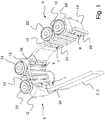
- the Fig. 1 shows a schematic perspective view of an embodiment of a drive 3 designed as a belt drive means 2 and a plurality of holding means 5 and 5 ', as they in various embodiments of a working module 1 according to the invention (cf. FIGS. 4 and 5 ) can be provided.
- the respective first wing 12 or 12 ' in this case forms a respective first fastening region 7, via which the respective first wing 12 or 12' is fixed to the belt 3.
- the respective second wing 14 or 14 ' forms a respective second fastening region 9 or 9', via which the respective second wing 14 or 14 'is secured to the belt 3.
- a respective first strip 24 or 24 ' is provided for the respective first fastening region 7 and 7', which is inserted into a toothing formed by the belt 3 and the belt 3 is clamped on the respective first wing 12 or 12 '. of the respective holding means 5 or 5 'sets.
- a respective second strip 26 or 26 ' is provided for the respective second fastening region 9 and 9', which is likewise inserted into a toothing formed by the belt 3 and the belt 3 is clamped to the respective second wing 14 or 14 'of the respective holding means 5 and 5 'sets.
- the strips 24, 24 ', 26 and 26' provided for the first fastening region 7 or 7 'and the second fastening region 9 and 9' lie flat against an inwardly directed side of the belt 3 in each case and put the belt 3 in a clamping manner respective holding means 5 and 5 'fixed.
- the respective strip 24, 24 ', 26 and 26' in each case extends at least approximately completely over an entire width of the belt 3.
- the first holding means 5 fastened to the belt 3 via the first fastening region 7 and the second fastening region 9 is located in an area in which the belt 5 is deflected.
- the second holding means 5 'fixed on the belt 3 via the first fastening region 7' and the second fastening region 9 ' are located in a region in which the drive means 2 or the belt 3 correspond Fig. 1 is moved in a linear direction.
- a synopsis of the first holding means 5 with the second holding means 5 'according to Fig. 1 illustrates here that the respective first wing 12 or 12 'can be pivoted with its respective first attachment region 7 or 7' relative to the respective second wing 14 or 14 'with its respective second attachment region 9 or 9'.
- the respective first wing 12 or 12 'and the respective second wing 14 or 14' pivotally connected to a common axis of rotation 13 or 13 'in connection.
- the respective holding means 5 or 5 'in the region of a deflection provided for the belt 3 can follow a curved direction of movement of the belt 3 and thereby from one for the second holding means 5' in FIG Fig. 1 shown orientation in the for the first holding means 5 in Fig. 1 shown orientation.
- the first holding means 5 comprises a first running and / or sliding roller 22 and a second running and / or sliding roller 24.
- the first running and / or sliding roller 22 and the second running and / or sliding roller 24 are respectively from the first holding means. 5 from and protrude laterally beyond the belt 3 out.
- the first running and / or sliding roller 22 and the second running and / or sliding roller 24 of the first holding means 5 in the course of a caused via the at least one belt 3 linear movement of the first holding means 5 each with a in the FIGS. 4 and 5 formed as part of the working module 1 rail 30 or 30 ', in which it is a support 31 and 31', are in surface contact.
- Both the first running and / or sliding roller 22 and the second running and / or sliding roller 24 are in surface contact with a side or surface of the rail 30 or 30 'which faces in the downward direction.
- the rail 30 or 30 ' is thus at least during a surface contact with the first running and / or sliding roller 22 or 22' and the second running and / or sliding roller 24 or 24 'above the respective first run and / or Slide roller 22 or 22 'and above the respective second running and / or sliding roller 24 or 24' positioned.
- the rail 30 or 30 'therefore provides, at least for a region in which the belt 3 follows an at least approximately linear direction of movement, via the first running and / or sliding roller 22 or 22' and the second running and / or sliding roller 24 or 24 'a positive guidance for the drive means 2 and the belt 3 ready.
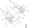
- the Fig. 2 shows a further schematic perspective view of the embodiment of a belt 3 and the holding means 5 and 5 'from Fig. 1 , Shown are also formed as part of the first holding means 5 first wing 12 and second wing 14 and the part of the second holding means 5 'formed first wing 12' and second wing 14 '.
- the leaves Fig. 2 now recognize about the respective holding means 5 and 5 'fixed to the belt 3 format part 28.
- the format part 28 is in Fig. 2 shown only in sections and in practice has an actual longitudinal extent along the axis of rotation 13, which over the in Fig. 2 shown longitudinal extent extends.
- the format part 28 or 28 'arranged on the respective holding means 5 or 5' can itself provide the respective common axis of rotation 13 around which the respective first fastening area 7 or 7 '(cf. Fig. 1 ) and the respective second fastening region 9 or 9 'are pivotable independently of one another.
- Articles or beverage containers can be pushed by means of several format parts 28 on a palletizer.
- the format parts 28 in this case come into surface contact with a plurality of articles of a respective palletizable layer on the back side and in this case push the respective palletizable layer onto a loading plate provided via the palletizer.
- Another format part 28 is provided, which is moved during the sliding without or at a short distance to leading articles or beverage containers of the respective palletizable layer and thereby prevents respective leading articles or beverage containers of a respective palettierstoryen position during the slide tilt unintentionally.
- the format part 28, which is fixed on the belt 3 via holding means 5 or 5 ' may also be formed by further format parts 28 which, with regard to the constructional structure and / or function, are of the kind shown in the figures of the present patent application Format part 28 differ.
- Format part 28 may be that groups of individual articles are formed by means of format parts 28, which are fastened to a respective belt 3 via holding means 5 or 5 '.
- format thermoplastic parts 28, which are fastened to a respective belt 3 via holding means 5 or 5 ' are used to apply planar thermoplastic packaging material to individual groups of articles.
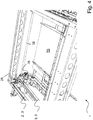
- the Fig. 3 shows a schematic plan view of the embodiment of a belt 3 and the plurality of holding means 5 and 5 'from the FIGS. 1 and 2 ,
- Fig. 3 recognize again the course or the orientation of the axis of rotation 13 around which the first wing 12 and the second wing 14 of the first holding means 5 can be pivoted.
- the axis of rotation 13 extends through the format part 28, which is fixed on the holding means 5 on the belt 3.
- FIGS. 1 and 2 yet to be recognized belt 3 is in Fig. 3 hidden by the holding means 5 and 5 '.
- Fig. 3 illustrates here that the first running and / or sliding roller 22 and the second running and / or sliding roller 24 each laterally beyond the in Fig. 3 by the holding means 5 and 5 'concealed belt 3 protrude.
- the first running and / or sliding roller 22 'and in Fig. 3 not to be recognized second running and / or sliding roller 24 'of the second holding means 5' is provided that the first running and / or sliding roller 22 'and the second running and / or sliding roller 24' of the second holding means 5 'laterally over the in Fig. 3 by the holding means 5 and 5 'concealed belt 3 protrude.
- the holding means 5 comprises a first intermediate piece 11 and a second intermediate piece 11 ', via which first intermediate piece 11 and second intermediate piece 11' the format part 28 is held.
- the format part 8 is held in each case pivotally via the first intermediate piece 11 and the second intermediate piece 11, so that the format part 28 itself provides the common axis of rotation 13 or so that the format part 28 itself forms the common axis of rotation 13.
- the format part 28 is thus held by the first intermediate piece 11 and the second intermediate piece 11 'such that the first intermediate piece 11 and the second intermediate piece 11' are independent of each other about a common axis of rotation extending through the format part 28 and possibly formed by the format part 28 itself 13 are pivotable.
- the first running and / or sliding roller 22 is arranged at the first intermediate piece 11 .
- the second running and / or sliding roller 24 is arranged at the second intermediate piece 11 '.
- a first pivot axis 15 extends through the first idler and / or roller 22 arranged on the first intermediate piece 11.
- the wing 12, which forms the first attachment portion 7 and the intermediate piece 11 are rotatable relative to each other about the first pivot axis 15.
- a second pivot axis 15 ' extends through the second running and / or sliding roller 24.
- the second wing 14, which forms the second mounting portion 9 and the second intermediate piece 11' are rotatable relative to each other about the second pivot axis 15 '.
- the holding means 5 has a high degree of flexibility and can thus follow the movement and expansion of the belt 3 in the region of a deflection.
- the Fig. 4 shows a schematic perspective view of an embodiment of a working module according to the invention 1.
- the working module 1 comprises a first circulating belt 3, on which over holding means 5 (see. FIGS. 1 to 3 ) a plurality of format parts 28 are arranged.
- the working module 1 comprises a second revolving belt 3 ', on which further on holding means 5 (see. FIGS. 1 to 3 ) a plurality of format parts 28 are arranged.
- the format parts 28 are not completely shown in the figures of this patent application.
- a further first circumferentially moving belt and a further second revolving belt are provided, which in Fig. 4 are not visible and are arranged on an opposite side of the transport area TB.
- driver shaft 32 Shown is also a driver shaft 32, which drives on opposite sides of the transport region TB belt coupled to each other.
- the over holding means 5 (see. FIGS. 1 to 3 ) on the first belt 3 fixed format parts 28 come into contact with articles of a respective palletizable layer back and thereby pushing the respective palettierShe position of articles on the transport area TB.
- the format parts 28 arranged on the second belt 3 ' are hereby moved with no or slight distance to the foremost articles of the respective palletizable layer together with the respective palletizable layer over the transport region TB and in this case prevent the respective foremost articles of a respective palletizable layer from being pushed tilt unintentionally.
- the Fig. 5 shows a schematic perspective view with individual details of the embodiment of a working module 1 according to Fig. 4 ,
- the first belt shown by reference numeral 3 is driven by the drive pulley 36. Further, a guide roller 37 is provided, which is in contact with the belt 3.
- a format part 28 communicating with the first belt 3 via a holding means 5 and a format part 28 communicating with the second belt 3 'via a holding means can be seen.
- a respective holding means 5 or 5 ' has a first running and / or sliding roller 22 or 22' as well as a second running and / or sliding roller 24 or 24.
- Fig. 5 now shows a first trained as a support 31 rail 30 which is associated with the first belt 3.
- Fig. 5 a second rail 30 'which is also formed as a second support 31' and the second belt 3 ' assigned.
- Running and / or sliding rollers 22, 22 'and 24 and 24' which are formed as part of fixed to the first belt 3 holding means 5 and 5 'are associated with the first belt 3 associated rail 30 and with the The first belt 3 associated support 31 in surface contact and are guided over the first belt 3 associated rail 30 and the first belt 3 associated with the support 31.
- Running and / or sliding rollers 22, 22 'and 24 and 24' which are formed as part of the second belt 3 fixed holding means 5 and 5 ', with the second belt 3 associated rail 30' and with the the second belt associated support 31 'in surface contact and are guided over the said second belt 3' associated rail 30 'and on the second belt 3' associated support 31 '. In this way, an unwanted torsion of the first belt 3 and the second belt 3 'can be counteracted.
- a respective guide 35 or 35 ' is provided in this region, which is in surface contact with the respective belt 3 or 3' ,
Landscapes
- Engineering & Computer Science (AREA)
- Mechanical Engineering (AREA)
- Structure Of Belt Conveyors (AREA)
Abstract
Es ist ein zum Umgang mit Artikeln und/oder Verpackungsmaterial ausgebildetes Arbeitsmodul für eine Verpackungsvorrichtung offenbart. Das Arbeitsmodul umfasst mindestens ein umlaufend geführtes Antriebsmittel (2) sowie mehrere Formatteile, die zum Einwirken auf Artikel und/oder zum Umgang mit Verpackungsmaterial ausgebildet sind. Weiter umfasst das Arbeitsmodul mehrere Haltemittel (5, 5').Es ist vorgesehen, dass das mindestens eine umlaufend geführte Antriebsmittel (2) wenigstens einen umlaufend geführten Riemen (3) umfasst, an welchen wenigstens einen umlaufend geführten Riemen (3) die mehreren zum Einwirken auf Artikel und/oder zum Umgang mit Verpackungsmaterial ausgebildeten Formatteile über die mehreren Haltemittel (5, 5') mechanisch gekoppelt sind.It is disclosed a trained for handling articles and / or packaging material working module for a packaging device. The working module comprises at least one circumferentially guided drive means (2) and a plurality of format parts which are designed to act on articles and / or for handling packaging material. It is provided that the at least one circulating drive means (2) comprises at least one circulating guided belt (3) on which at least one circulating guided belt (3), the plurality of Acting on articles and / or for handling packaging material formed format parts on the plurality of holding means (5, 5 ') are mechanically coupled.
Description
Die vorliegende Erfindung betrifft ein Arbeitsmodul für eine Verpackungsvorrichtung und ein Verfahren zum Umgang mit Artikeln und/oder Verpackungsmaterial.The present invention relates to a working module for a packaging device and a method for handling articles and / or packaging material.
Für eine Zusammenstellung von einzelnen Gruppen von Artikeln und ihre nachfolgende Verpackung werden in der Praxis Reihen an Artikeln parallel zueinander bewegt, wobei aufeinanderfolgende Artikel aneinander anstehen können. Um einzelne Gruppen von Artikeln aus diesen in mehreren Reihen parallel zueinander bewegten Artikeln zu bilden, kann es sein, dass eine bestimmte Anzahl an vorauseilenden Artikeln gegenüber nachfolgenden Artikeln kurzzeitig beschleunigt wird. Hierzu können Einteilstäbe vorgesehen sein, welche rückseitig mit der bestimmten Anzahl an Artikeln in Anlage treten und die Artikel der bestimmten Anzahl sodann gegenüber den nachfolgenden Artikeln kurzzeitig beschleunigen. Auch gibt es Verpackungsvorrichtungen, bei welchen mittels solcher Einteilstäbe nachfolgende Artikel gegenüber den vorauseilenden Artikeln kurzzeitig verzögert werden. Bei beiden Ausführungsformen wird zwischen der bestimmten Anzahl an vorauseilenden Artikeln und nachfolgenden Artikeln eine relative Beabstandung gebildet, wodurch Gruppen an Artikeln entstehen, auf welche nachfolgend Verpackungsmaterial aufgebracht werden kann. Die Einteilstäbe sind an umlaufend bewegten Förderketten angeordnet. Der jeweilige relative Abstand bzw. Teilungsabstand von an den umlaufend bewegten Förderketten angeordneten Einteilstäben zueinander ist hierbei auf die jeweilige aus Artikeln zu bildende Gruppe abgestimmt.For a collection of individual groups of articles and their subsequent packaging, in practice, rows of articles are moved parallel to one another, whereby successive articles may be contiguous. In order to form individual groups of articles from these articles, which move in several rows parallel to one another, a certain number of leading articles may be briefly accelerated compared to subsequent articles. For this purpose, one-piece rods may be provided, which come into contact with the specified number of articles on the back and then accelerate the articles of the specified number in relation to the subsequent articles for a short time. There are also packaging devices in which by means of such Einteilstäbe subsequent articles are delayed against the leading articles for a short time. In both embodiments, a relative spacing is formed between the particular number of leading articles and subsequent articles, thereby creating groups of articles to which packaging material may subsequently be applied. The dividing bars are arranged on continuously moving conveyor chains. The respective relative distance or pitch of arranged at the circumferentially moving conveyor chains Einteilstäben each other is here matched to the respective group of articles to be formed.
Um die jeweiligen Gruppen an Artikeln mit Verpackungsmaterial zu versehen, besitzen Verpackungsvorrichtungen häufig eine Vielzahl an umlaufend bzw. rotierend bewegten Einschlagstäben, welche flächiges und ggf. durch Schrumpffolie oder Stretchfolie ausgebildetes Verpackungsmaterial auf eine jeweilige Gruppe an Artikeln aufbringen. Solche Einschlagstäbe sind in der Praxis zur umlaufenden bzw. rotierenden Bewegung an Förderketten angeordnet.In order to provide the respective groups of articles with packaging material, packaging devices often have a multiplicity of revolving or turning impact bars, which apply flat and optionally shrink-wrapped or stretch-formed packaging material to a respective group of articles. Such impact bars are arranged in practice for circulating or rotating movement on conveyor chains.
Umlaufende Förderketten, wie sie bei Verpackungsvorrichtungen beispielsweis zur Bewegung von Einschlagstäben und/oder Einteilstäben Verwendung finden, besitzen hohe Anschaffungskosten und müssen in regelmäßigen Abständen gewartet oder ersetzt werden. Da bei Verpackungsvorrichtungen verwendete Förderketten aus mehreren einzelnen Gliedern bestehen, die aus Metall gebildet sind, ist ein jeweiliger Betrieb einer solchen Verpackungsvorrichtung mit einer unerwünscht hohen Lautstärke verbunden.Circulating conveyor chains, as used in packaging devices, for example, for the movement of impact bars and / or Einteilstäben use own high initial costs and must be serviced or replaced at regular intervals. Since conveyor chains used in packaging devices consist of several individual members formed of metal, a respective operation of such a packaging device is associated with an undesirably high volume.
Eine vorrangige Aufgabe der Erfindung kann daher insbesondere darin gesehen werden, eine praktikable, unaufwendig zu realisierende und kostengünstige Möglichkeit bereitzustellen, mittels welcher die genannten Nachteile zumindest teilweise beseitigt werden.A primary object of the invention can therefore be seen in particular to provide a practicable, inexpensive to implement and cost-effective means by which the disadvantages mentioned are at least partially eliminated.
Die Aufgabe der Erfindung wird durch ein Arbeitsmodul und ein Verfahren gelöst, welche die Merkmale in den unabhängigen Ansprüchen umfassen. Weitere vorteilhafte Ausgestaltungen werden durch die Unteransprüche beschrieben.The object of the invention is achieved by a working module and a method comprising the features in the independent claims. Further advantageous embodiments are described by the subclaims.
Die Erfindung betrifft ein zum Umgang mit Artikeln und/oder Verpackungsmaterial ausgebildetes Arbeitsmodul für eine Verpackungsvorrichtung. Die Verpackungsvorrichtung kann mehrere einzelne Module besitzen, mittels welchen Gruppen aus Artikeln gebildet werden und/oder mittels welchen Verpackungsmaterial auf Artikel aufgebracht wird und/oder mittels welchen palettierfähige Lagen auf eine zugeordnete Palette überführt werden. Das Arbeitsmodul kann in denkbaren Ausführungsformen als ein solches Modul ausgebildet sein, welches Bestandteil der Verpackungsvorrichtung ist.The invention relates to a trained for handling articles and / or packaging material working module for a packaging device. The packaging device may have a plurality of individual modules by means of which groups of articles are formed and / or by means of which packaging material is applied to articles and / or by means of which palletizable layers are transferred to an associated pallet. The working module can be designed in conceivable embodiments as such a module which is part of the packaging device.
Das Arbeitsmodul umfasst mindestens ein umlaufend geführtes Antriebsmittel. Weiter umfasst das Arbeitsmodul mehrere Formatteile, die zum Einwirken auf Artikel und/oder zum Umgang mit Verpackungsmaterial ausgebildet sind. Auch umfasst das Arbeitsmodul mehrere Haltemittel.The working module comprises at least one circulating drive means. Furthermore, the working module comprises a plurality of format parts which are designed to act on articles and / or for handling packaging material. Also, the working module comprises a plurality of holding means.
Es ist vorgesehen, dass das mindestens eine umlaufend geführte Antriebsmittel wenigstens einen umlaufend geführten Riemen umfasst, an welchen wenigstens einen umlaufend geführten Riemen die mehreren zum Einwirken auf Artikel und/oder zum Umgang mit Verpackungsmaterial ausgebildeten Formatteile über die mehreren Haltemittel mechanisch gekoppelt sind. Vorteilhafterweise besitzen Riemen gegenüber Förderketten geringere Anschaffungskosten und zeichnen sich gegenüber Förderketten durch einen Betrieb mit geringem Geräuschpegel aus.It is provided that the at least one circumferentially guided drive means comprises at least one circumferentially guided belt, to which at least one circulating guided belt, the plurality of formed for acting on articles and / or handling packaging material format parts are mechanically coupled via the plurality of holding means. Advantageously, belts have lower acquisition costs compared to conveyor chains and are distinguished from conveyor chains by low-noise operation.
Es kann sein, dass die mehreren Haltemittel jeweils über wenigstens zwei Befestigungsbereiche am wenigstens einen umlaufend geführten Riemen angeordnet sind, wobei die jeweiligen wenigstens zwei Befestigungsbereich im Hinblick auf den Umfangsverlauf des wenigstens einen umlaufend geführten Riemens versetzt zueinander positioniert sind. Somit können die wenigstens zwei Befestigungsbereiche beabstandet zueinander am wenigstens einen umlaufend geführten Riemen positioniert sein.It may be that the plurality of holding means in each case arranged on at least two attachment regions on at least one circulating guided belt are, wherein the respective at least two mounting portion are positioned offset from each other with respect to the circumferential course of the at least one circumferentially guided belt. Thus, the at least two attachment regions can be positioned spaced apart from each other on at least one circumferentially guided belt.
Bewährt haben sich in der Praxis Ausführungsformen, bei welchen jedem der wenigstens zwei Befestigungsbereiche eine Leiste zugeordnet ist, welche jeweilige Leiste in eine durch eine Verzahnung des wenigstens einen umlaufend geführten Riemens ausgebildete Nut eingesetzt ist und welche jeweilige Leiste das jeweilige Haltemittel klemmend am wenigstens einen umlaufend geführten Riemen festsetzt. Beispielsweise kann für jede Leiste wenigstens eine Schraubverbindung vorgesehen sein, welche wenigstens eine Schraubverbindung den wenigstens einen umlaufend geführten Riemen durchsetzt und hierbei die jeweilige Leiste an einem als Bestandteils des jeweiligen Haltemittels ausgebildeten Flügel festsetzt.Have proven useful in practice embodiments in which each of the at least two attachment areas is assigned a bar, which respective bar is inserted into a formed by a toothing of at least one circumferentially guided belt groove and which respective bar clamping the respective holding means on at least one circumferential fixed belt. For example, at least one screw connection can be provided for each strip, which passes through at least one screw the at least one circumferentially guided belt and in this case fixes the respective strip on a formed as part of the respective holding means wing.
Auch können die mehreren Haltemittel ihre jeweiligen wenigstens zwei Befestigungsbereiche zueinander abstandsveränderlich ausbilden. Bewährt haben sich hierzu Ausführungsformen, bei welchen die mehreren Haltemittel jeweils mindestens eine Drehachse besitzen, um welche die jeweiligen wenigstens zwei Befestigungsbereiche eines jeweiligen Haltemittels unabhängig voneinander schwenkbar sind. Mittels einer Schwenkbewegung können die mehreren Haltemittel somit ggf. ihren Abstand zueinander verändern.Also, the plurality of holding means may form their respective at least two attachment regions spaced from one another. For this purpose, embodiments in which the plurality of holding means each have at least one axis of rotation about which the respective at least two attachment areas of a respective holding means are pivotable independently of one another have proved successful. By means of a pivoting movement, the plurality of holding means can thus possibly change their distance from one another.
Durch die umlaufende Führung des wenigstens einen Riemens kann es sein, dass eine im Bereich einer Umlenkung befindliche Partie des wenigstens einen umlaufend geführten Riemens temporär gedehnt wird bzw. temporär reversibel elastisch verformt wird. Bei einer solchen Dehnung können die ggf. abstandsveränderlich ausgebildeten und an der im Bereich der Umlenkung befindlichen Partie angeordneten wenigstens zwei Befestigungsbereiche eines jeweiligen Haltemittels ihren relativen Abstand vergrößern und hierbei der temporären Dehnung bzw. der temporären reversiblen elastischen Verformung der Partie folgen. Verlässt die jeweilige Partie hierauf den Bereich der Umlenkung, so kann sich die bis dahin noch gedehnte Partie zusammenziehen bzw. die bis dahin noch reversibel elastisch verformte Partie rückverformen, wobei die wenigstens zwei weiterhin im Bereich der Partie festgesetzten Befestigungsbereiche des jeweiligen Haltemittels ihren relativen Abstand zueinander verkleinern bzw. sich einander annähern.Due to the circumferential guidance of the at least one belt, it may be that a portion of the at least one circulating belt located in the region of a deflection is temporarily stretched or is temporarily reversibly elastically deformed. With such an elongation, the possibly space-variable and arranged at the located in the region of the deflection lot arranged at least two mounting portions of a respective holding means can increase their relative distance and in this case the temporary stretching or the temporary reversible elastic deformation of the lot follow. If the respective batch leaves the area of the deflection, the previously stretched portion may contract or deform the previously reversibly elastically deformed portion, wherein the at least two fixing areas of the respective holding means which are still fixed in the area of the portion maintain their relative distance from each other zoom out or approach each other.
Um den wenigstens einen Riemen umlaufend zu führen, kann das Arbeitsmodul über mindestens eine Umlenkrolle und/oder über mindestens eine Antriebsrolle verfügen. Insbesondere bei solchen Ausführungsformen hat es sich bewährt, wenn die mehreren Haltemittel jeweils eine gemeinsame Drehachse für die jeweiligen wenigstens zwei Befestigungsbereiche besitzen, um welche jeweilige gemeinsame Drehachse die jeweiligen wenigstens zwei Befestigungsbereich eines jeweiligen Haltemittels unabhängig voneinander schwenkbar sind. Insbesondere kann es sein, dass die mehreren Haltemittel jeweils eine gemeinsame Drehachse für die jeweiligen wenigstens zwei Befestigungsbereich besitzen, um welche jeweilige gemeinsame Drehachse die jeweiligen wenigstens zwei Befestigungsbereich eines jeweiligen Haltemittels unabhängig voneinander schwenkbar sind, wobei die jeweiligen wenigstens zwei Befestigungsbereiche im Verlauf einer jeweiligen Schwenkbewegung um die gemeinsame Drehachse einer Kreisbahn folgen. Bei solchen Ausführungsformen können die wenigstens zwei Befestigungsbereiche im Bereich einer jeweiligen Umlenkrolle und/oder Antriebsrolle um die jeweilige gemeinsame Drehachse geschwenkt werden. Eine Rotationsachse der Umlenkrolle bzw. der Antriebsrolle und die Drehachse können parallel oder im Wesentlichen parallel zueinander orientiert sein.In order to guide the at least one belt circumferentially, the working module can have at least one deflection roller and / or at least one drive roller. In particular, in such embodiments, it has proven useful if the plurality of holding means each have a common axis of rotation for the respective at least two mounting areas about which respective common axis of rotation the respective at least two mounting portion of a respective holding means are independently pivotable. In particular, it may be that the plurality of holding means each have a common axis of rotation for the respective at least two mounting portion about which respective common axis of rotation the respective at least two mounting portion of a respective holding means are independently pivotable, wherein the respective at least two mounting portions in the course of a respective pivoting movement to follow the common axis of rotation of a circular path. In such embodiments, the at least two attachment regions can be pivoted about the respective common axis of rotation in the region of a respective deflection roller and / or drive roller. An axis of rotation of the deflection roller or of the drive roller and the axis of rotation can be oriented parallel or substantially parallel to one another.
Weiter können die mehreren Haltemittel für einen jeweiligen ersten Befestigungsbereich eine jeweilige erste Schwenkachse ausbilden, um welche der jeweilige erste Befestigungsbereich gedreht werden kann. Zudem können die mehreren Haltemittel für einen jeweiligen zweiten Befestigungsbereich eine jeweilige zweite Schwenkachse ausbilden, um welche jeweilige zweite Schwenkachse der jeweilige zweite Befestigungsbereich gedreht werden kann. Die erste Schwenkachse und die zweite Schwenkachse eines jeweiligen Haltemittels können entlang des Umfangsverlaufs des jeweiligen wenigstens einen umlaufend geführten Riemens versetzt und vorzugsweise parallel zueinander orientiert sein.Further, the plurality of holding means for each respective first attachment area may form a respective first pivot axis about which the respective first attachment area can be rotated. In addition, the plurality of holding means for a respective second attachment region may form a respective second pivot axis about which respective second pivot axis the respective second attachment region may be rotated. The first pivot axis and the second pivot axis of a respective holding means can be offset along the circumferential course of the respective at least one circumferentially guided belt and preferably oriented parallel to each other.
Denkbar ist zudem, dass die mehreren Haltemittel jeweils eine gemeinsame Drehachse für die jeweiligen wenigstens zwei Befestigungsbereiche besitzen, um welche jeweilige gemeinsame Drehachse die jeweiligen wenigstens zwei Befestigungsbereiche eines jeweiligen Haltemittels unabhängig voneinander schwenkbar sind. Zusätzlich kann es sein, dass die mehreren Haltemittel für einen jeweiligen ersten Befestigungsbereich eine jeweilige erste Schwenkachse ausbilden, um welche der jeweilige erste Befestigungsbereich gedreht werden kann und dass die mehreren Haltemittel für einen jeweiligen zweiten Befestigungsbereich eine jeweilige zweite Schwenkachse ausbilden, um welche jeweilige zweite Schwenkachse der jeweilige zweite Befestigungsbereich gedreht werden kann. Die erste Schwenkachse, die zweite Schwenkachse und die gemeinsame Drehachse können entlang des Umfangsverlaufs des jeweiligen wenigstens einen umlaufend geführten Riemens versetzt und parallel zueinander orientiert sein. Insbesondere kann die gemeinsame Drehachse hierbei zwischen der ersten Schwenkachse und der zweiten Schwenkachse angeordnet sein.It is also conceivable that the plurality of holding means each have a common axis of rotation for the respective at least two mounting areas about which respective common axis of rotation the respective at least two mounting portions of a respective holding means are independently pivotable. Additionally, it may be that the plurality of retaining means for a respective first attachment portion form a respective first pivot axis about which the respective first attachment portion can be rotated and the plurality of retaining means for a respective second attachment portion form a respective second pivot axis about each respective second pivot axis the respective second attachment area can be turned. The first pivot axis, the second pivot axis and the common axis of rotation can be offset along the circumferential course of the respective at least one circumferentially guided belt and oriented parallel to each other. In particular, the common axis of rotation can in this case be arranged between the first pivot axis and the second pivot axis.
Auch können die mehreren Haltemittel eine jeweilige insbesondere als Aufnahme ausgebildete Befestigung für ein jeweiliges Formatteil bereitstellen, wobei die insbesondere als Aufnahme ausgebildete Befestigung und die gemeinsame Drehachse fluchtend zueinander orientiert sind. In denkbaren Ausführungsformen kann das jeweilige Formatteil selbst die gemeinsame Drehachse ausbilden bzw. die gemeinsame Drehachse bereitstellen.The plurality of holding means may also provide a respective attachment designed in particular as a receptacle for a respective format part, wherein the attachment formed in particular as a receptacle and the common axis of rotation are oriented in alignment with one another. In conceivable embodiments, the respective format part itself may form the common axis of rotation or provide the common axis of rotation.
Weiter kann das Arbeitsmodul mindestens eine vorzugsweise als Schiene ausgebildete Stütze umfassen. Hierbei kann vorgesehen sein, dass die mindestens eine vorzugsweise als Schiene ausgebildete Stütze derart positioniert ist, dass die mehreren Haltemittel im Verlauf einer über den wenigstens einen Riemen bewirkten und im Wesentlichen linearen Bewegung mit der mindestens einen vorzugsweise als Schiene ausgebildeten Stütze in Oberflächenkontakt stehen.Further, the working module may comprise at least one preferably designed as a rail support. In this case, it can be provided that the at least one preferably designed as a rail support is positioned such that the plurality of holding means are in the course of an over the at least one belt caused and substantially linear movement with the at least one preferably designed as a rail support in surface contact.
Auch kann es sein, dass die mehreren Haltemittel jeweils mindestens eine seitlich vom jeweiligen Haltemittel abstehende Lauf- und/oder Gleitrolle besitzen, über welche jeweilige mindestens eine seitlich vom jeweiligen Haltemittel abstehende Lauf- und/oder Gleitrolle das jeweilige Haltemittel mit der mindestens einen vorzugsweise als Schiene ausgebildeten Stütze in Oberflächenkontakt steht.It may also be that the plurality of holding means each have at least one laterally extending from the respective holding means running and / or sliding roller, via which respective at least one laterally projecting from the respective holding means running and / or sliding roller the respective holding means with the at least one preferably as Rail trained support is in surface contact.
Weiter haben sich Ausführungsformen bewährt, bei welchen die mehreren Haltemittel jeweils mindestens eine erste seitlich vom jeweiligen Haltemittel abstehende Lauf- und/oder Gleitrolle sowie jeweils mindestens eine zweite vom jeweiligen Haltemittel seitlich abstehende Lauf- und/oder Gleitrolle umfassen, wobei die mehreren Haltemittel über ihre ersten und zweiten Lauf- und/oder Gleitrollen mit der mindestens einen vorzugsweise als Schiene ausgebildeten Stütze in Oberflächenkontakt stehen. Hierbei kann vorgesehen sein, dass die erste Lauf- und/oder Gleitrolle und die zweiten Lauf- und/oder Gleitrolle eines jeweiligen Haltemittels unabhängig voneinander um die gemeinsame Drehachse eines jeweiligen Haltemittels schwenkbar sind.Further, embodiments have proven, in which the plurality of holding means each comprise at least one first laterally extending from the respective holding means running and / or sliding roller and at least one second from the respective holding means laterally projecting running and / or sliding roller, wherein the plurality of holding means on their first and second running and / or sliding rollers with the at least one preferably designed as a rail support in surface contact. It can be provided that the first running and / or sliding roller and the second running and / or sliding roller of a respective holding means are independently pivotable about the common axis of rotation of a respective holding means.
Die Erfindung betrifft darüber hinaus ein Verfahren zum Umgang mit Artikeln und/oder Verpackungsmaterial. Für das Verfahren bzw. zur Umsetzung des Verfahrens ist ein Arbeitsmodul gemäß einer Ausführungsform der vorhergehenden Beschreibung vorgesehen. Weiter ist für das erfindungsgemäße Verfahren vorgesehen, dass der wenigstens eine umlaufend geführte Riemen rotierend bewegt wird, woraus resultierend die mehreren Formatteile auf Artikel einwirken und/oder woraus resultierend die mehreren Formatteile Verpackungsmaterial auf Artikel aufbringen.The invention further relates to a method for handling articles and / or packaging material. For the method or implementation of the method is a working module according to an embodiment of the foregoing description is provided. Furthermore, it is provided for the method according to the invention that the at least one circulating guided belt is moved in rotation, as a result of which the several format parts act on articles and / or as a result the multiple format parts apply packaging material to articles.
Die nachfolgenden Ausführungen fassen nochmal einige Aspekte der zuvor bereits in verschiedenen Ausführungsvarianten erläuterten Erfindung zusammen, konkretisieren einige Aspekte, sollen jedoch nicht im Widerspruch zu den bereits gemachten Ausführungen gesehen werden, sondern in Zusammenschau, bei Zweifeln ggf. als speziellere Ausführungsvarianten und/oder Abwandlungen. So kann, wie bereits oben mehrfach erwähnt, das erfindungsgemäße Arbeitsmodul Teil eines Antriebsmittels sein, das bspw. als Riemen ausgebildet sein kann. Das Arbeitsmodul kann über mehrere Haltemittel verfügen. Jedes dieser Haltemittel kann jeweils einen ersten Flügel und einen zweiten Flügel umfassen. Der jeweilige erste Flügel bildet hierbei einen ersten Befestigungsbereich aus, über welchen der jeweilige erste Flügel am Riemen festgesetzt ist.The following statements again summarize some aspects of the invention previously explained in various embodiments, concretizing some aspects, but should not be contradicted by the statements already made, but in synopsis, if necessary, as more specific embodiments and / or modifications. Thus, as already mentioned several times above, the working module according to the invention may be part of a drive means which, for example, may be designed as a belt. The working module can have several holding means. Each of these retaining means may each comprise a first wing and a second wing. In this case, the respective first wing forms a first fastening region, via which the respective first wing is secured to the belt.
Weiter bildet der zweite Flügel einen zweiten Befestigungsbereich aus, über welchen der jeweilige zweite Flügel am Riemen festgesetzt ist. Wahlweise kann für den jeweiligen ersten Befestigungsbereich eine erste Leiste vorgesehen sein, die in eine durch den Riemen ausgebildete Verzahnung eingesetzt ist und den Riemen klemmend am jeweiligen ersten Flügel des jeweiligen Haltemittels festsetzt. Zudem kann für den zweiten Befestigungsbereich eine zweite Leiste vorgesehen sein, die ebenso in eine durch den Riemen ausgebildete Verzahnung eingesetzt ist und den Riemen klemmend am jeweiligen zweiten Flügel des jeweiligen Haltemittels festsetzt.Furthermore, the second wing forms a second fastening region, via which the respective second wing is secured to the belt. Optionally, a first strip may be provided for the respective first fastening region, which is inserted into a toothing formed by the belt and clamps the belt on the respective first wing of the respective retaining means. In addition, a second strip may be provided for the second fastening region, which is also inserted into a toothing formed by the belt and clamps the belt on the respective second wing of the respective holding means.
Die für den ersten Befestigungsbereich und den zweiten Befestigungsbereich vorgesehenen Leisten liegen vorzugsweise jeweils an einer nach innen gewandten Seite des Riemens flächig an und setzen den Riemen klemmend am jeweiligen Haltemittel fest. Die jeweilige Leiste erstreckt sich hierbei jeweils zumindest näherungsweise vollständig über eine gesamte Breite des Riemens.The strips provided for the first fastening region and the second fastening region are preferably in each case flat against an inwardly directed side of the belt and fix the belt by clamping on the respective retaining means. The respective strip extends in each case at least approximately completely over an entire width of the belt.
Das erste über den ersten Befestigungsbereich und den zweiten Befestigungsbereich am Riemen befestigte Haltemittel befindet sich in einem Bereich, in welchem der Riemen umgelenkt wird. Hingegen befindet sich das über den ersten Befestigungsbereich und den zweiten Befestigungsbereich am Riemen festgesetzte zweite Haltemittel in einem Bereich, in welchem das Antriebsmittel bzw. der Riemen in linearer Richtung bewegt wird. Der erste Flügel kann mit seinem ersten Befestigungsbereich gegenüber dem zweiten Flügel mit seinem zweiten Befestigungsbereich geschwenkt werden. Hierzu stehen der jeweilige erste Flügel und der jeweilige zweite Flügel schwenkbar mit einer gemeinsamen Drehachse in Verbindung. Vorteilhafterweise kann das jeweilige Haltemittel im Bereich einer für den Riemen vorgesehenen Umlenkung einer kurvenförmigen Bewegungsrichtung des Riemens folgen und hierdurch aus einer Orientierung des zweiten Haltemittels in eine Orientierung des ersten Haltemittels gelangen.The first holding means fastened to the belt via the first fastening region and the second fastening region is located in an area in which the belt is deflected. On the other hand, this is fixed over the first fastening area and the second fastening area on the belt second holding means in a region in which the drive means or the belt is moved in the linear direction. The first wing can be pivoted with its first attachment region relative to the second wing with its second attachment region. For this purpose, the respective first wing and the respective second wing are pivotally connected to a common axis of rotation. Advantageously, the respective holding means in the region of a deflection provided for the belt can follow a curved direction of movement of the belt and thereby pass from an orientation of the second holding means into an orientation of the first holding means.
Das erste Haltemittel kann eine erste Lauf- und/oder Gleitrolle sowie eine zweite Lauf- und/oder Gleitrolle umfassen. Die erste Lauf- und/oder Gleitrolle und die zweite Lauf- und/oder Gleitrolle stehen jeweils vom ersten Haltemittel ab und ragen hierbei seitlich über den Riemen hinaus. Hierdurch können die die erste Lauf- und/oder Gleitrolle sowie die zweite Lauf- und/oder Gleitrolle des ersten Haltemittel im Verlauf einer über den wenigstens einen Riemen bewirkten linearen Bewegung des ersten Haltemittels jeweils mit einer vorzugsweise als Bestandteil des Arbeitsmoduls ausgebildeten Schiene, bei welcher es sich um eine Stütze handeln kann, in Oberflächenkontakt stehen.The first holding means may comprise a first running and / or sliding roller and a second running and / or sliding roller. The first running and / or sliding roller and the second running and / or sliding roller each protrude from the first holding means and protrude laterally beyond the belt. In this way, the first running and / or sliding roller and the second running and / or sliding roller of the first holding means in the course of a caused via the at least one belt linear movement of the first holding means in each case with a preferably formed as part of the working module rail in which it can be a support, be in surface contact.
Hierdurch können sowohl die erste Lauf- und/oder Gleitrolle als auch die zweite Lauf- und/oder Gleitrolle jeweils mit einer in Richtung nach unten gewandten Seite bzw. Fläche der Schiene in Oberflächenkontakt stehen. Die Schiene ist somit zumindest während eines Oberflächenkontaktes zu der ersten Lauf- und/oder Gleitrolle und der zweiten Lauf- und/oder Gleitrolle oberhalb der jeweiligen ersten Lauf- und/oder Gleitrolle sowie oberhalb der jeweiligen zweiten Lauf- und/oder Gleitrolle positioniert.As a result, both the first running and / or sliding roller and the second running and / or sliding roller can each be in surface contact with a side or surface of the rail facing downwards. The rail is thus positioned at least during a surface contact with the first running and / or sliding roller and the second running and / or sliding roller above the respective first running and / or sliding roller and above the respective second running and / or sliding roller.
Durch den Oberflächenkontakt zwischen der ersten Lauf- und/oder Gleitrolle und der zweiten Lauf- und/oder Gleitrolle und der Schiene kann einer ungewollten Torsion des Riemens entgegengewirkt werden. Die Schiene stellt daher zumindest für einen Bereich, in welchem der Riemen einer zumindest näherungsweise linearen Bewegungsrichtung folgt, über die erste Lauf- und/oder Gleitrolle und die zweite Lauf- und/oder Gleitrolle eine Zwangsführung für das Antriebsmittel bzw. den Riemen bereit.By the surface contact between the first running and / or sliding roller and the second running and / or sliding roller and the rail, an unwanted torsion of the belt can be counteracted. Therefore, at least for a region in which the belt follows an at least approximately linear direction of movement, the rail provides positive guidance for the drive means or the belt via the first running and / or sliding roller and the second running and / or sliding roller.
Weiterhin kann ein über das jeweilige Haltemittel am Riemen festgesetzte Formatteil vorgesehen sein. Das am Haltemittel angeordnete Formatteil kann hierbei selbst eine gemeinsame Drehachse bereitstellen, um welche der erste Befestigungsbereich und der zweite Befestigungsbereich unabhängig voneinander schwenkbar sind.Furthermore, a fixed on the respective holding means on the belt format part can be provided. The format part arranged on the holding means can in this case itself provide a common axis of rotation about which the first one Attachment area and the second attachment area are independently pivotable.
Mittels der hier beschriebenen Vorrichtung können bspw. Artikel bzw. Getränkebehälter mittels mehrerer Formatteile auf einen Palettierer geschoben werden. Die Formatteile treten hierbei mit mehreren Artikeln einer jeweiligen palettierfähigen Lage rückseitig in Oberflächenkontakt und schieben hierbei die jeweilige palettierfähige Lage auf eine über den Palettierer bereitgestellte Beladeplatte.By means of the device described here, for example, articles or beverage containers can be pushed onto a palletizer by means of several format parts. In this case, the format parts come into surface contact with a plurality of articles of a respective palletizable layer on the back side and in this case push the respective palletizable layer onto a loading plate provided via the palletizer.
Ein weiteres Formatteil kann vorgesehen sein, welches während des Schiebens ohne oder mit geringem Abstand zu vorauseilenden Artikeln bzw. Getränkebehältern der jeweiligen palettierfähigen Lage bewegt wird und hierbei verhindert, dass jeweilige vorauseilende Artikel bzw. Getränkebehälter einer jeweiligen palettierfähigen Lage während des Schiebens ungewollt kippen.Another format part can be provided, which is moved during the sliding without or with little distance to leading articles or beverage containers of the respective palletizable layer and thereby prevents respective leading article or beverage container of a respective palettierfähigen position during the slide tilt unintentionally.
In der Praxis kann das Formatteil, welches über Haltemittel am Riemen festgesetzt ist, auch durch weitere Formatteile ausgebildet sein, die sich hinsichtlich des konstruktiven Aufbaus und/oder der Funktion von den hier beschriebenen Formatteilen unterscheiden können. So kann es beispielsweise sein, dass über Formatteile, die über Haltemittel an einem jeweiligen Riemen festgesetzt sind, Gruppen aus einzelnen Artikeln gebildet werden. Auch kann es beispielsweise sein, dass über Formatteile, die über Haltemittel an einem jeweiligen Riemen festgesetzt sind, flächiges thermoplastisches Verpackungsmaterial auf einzelne Gruppen an Artikeln aufgebracht wird.In practice, the format part, which is set on holding means on the belt, may also be formed by further format parts, which may differ with regard to the structural design and / or the function of the format parts described here. Thus, for example, groups may be formed from individual articles via format parts which are fastened to a respective belt via retaining means. It may also be the case, for example, that format thermoplastic parts, which are fastened to a respective belt via holding means, are used to apply planar thermoplastic packaging material to individual groups of articles.
Die erwähnte Drehachse verläuft durch das Formatteil, welches über das Haltemittel am Riemen festgesetzt ist. Die erste Lauf- und/oder Gleitrolle und die zweite Lauf- und/oder Gleitrolle können jeweils seitlich über den Riemen hinausragen. Auch für die erste Lauf- und/oder Gleitrolle und die zweite Lauf- und/oder Gleitrolle des zweiten Haltemittels kann vorgesehen sein, dass die erste Lauf- und/oder Gleitrolle und die zweite Lauf- und/oder Gleitrolle des zweiten Haltemittels seitlich über den Riemen hinausragen.The aforementioned axis of rotation passes through the format part, which is fixed on the holding means on the belt. The first running and / or sliding roller and the second running and / or sliding roller can each protrude laterally beyond the belt. It can also be provided for the first running and / or sliding roller and the second running and / or sliding roller of the second holding means that the first running and / or sliding roller and the second running and / or sliding roller of the second holding means laterally over the Protrude belt.
Das Haltemittel kann wahlweise ein erstes Zwischenstück und ein zweites Zwischenstück umfassen, die gemeinsam das Formatteil halten. Das Formatteil wird über das erste Zwischenstück und das zweite Zwischenstück jeweils schwenkbeweglich gehalten, so dass das Formatteil selbst die gemeinsame Drehachse bereitstellt oder ausbildet. Insbesondere wird das Formatteil vom ersten Zwischenstück und vom zweiten Zwischenstück somit derart gehalten, dass das erste Zwischenstück und das zweite Zwischenstück unabhängig voneinander um eine durch das Formatteil verlaufende und ggf. durch das Formatteil selbst ausgebildete gemeinsame Drehachse schwenkbar sind.The holding means may optionally comprise a first intermediate piece and a second intermediate piece, which together hold the format part. The format part is held in each case pivotally via the first intermediate piece and the second intermediate piece, so that the format part itself provides or forms the common axis of rotation. In particular, the format part of the first intermediate piece and the second intermediate piece is thus held such that the first intermediate piece and the second Intermediate piece are independently pivotable about a running through the format part and possibly formed by the format part itself common axis of rotation.
Am ersten Zwischenstück ist die erste Lauf- und/oder Gleitrolle angeordnet. Am zweiten Zwischenstück ist die zweite Lauf- und/oder Gleitrolle angeordnet. Somit sind die erste Lauf- und/oder Gleitrolle und die zweite Lauf- und/oder Gleitrolle zusammen mit dem jeweiligen Zwischenstück um die gemeinsame Drehachse schwenkbar.At the first intermediate piece, the first running and / or sliding roller is arranged. At the second intermediate piece, the second running and / or sliding roller is arranged. Thus, the first running and / or sliding roller and the second running and / or sliding roller are pivotable together with the respective intermediate piece about the common axis of rotation.
Weiterhin kann vorgesehen sein, dass eine erste Schwenkachse durch die am ersten Zwischenstück angeordnete erste Lauf- und/oder Gleitrolle verläuft. Der Flügel, welcher den ersten Befestigungsbereich ausbildet und das Zwischenstück können um diese erste Schwenkachse relativ zueinander verdreht oder verschwenkt werden. Ebenso verläuft eine zweite Schwenkachse durch die zweite Lauf- und/oder Gleitrolle. Der zweite Flügel, welcher den zweiten Befestigungsbereich ausbildet, und das zweite Zwischenstück sind somit vorzugsweise um diese zweite Schwenkachse relativ zueinander drehbar. Durch die durch das erste Haltemittel ausgebildete gemeinsame Drehachse, die erste Schwenkachse 15 und die zweite Schwenkachse besitzt das Haltemittel eine hohe Flexibilität und kann hierdurch der Bewegung und Dehnung des Riemens im Bereich einer Umlenkung folgen.Furthermore, it may be provided that a first pivot axis extends through the first runner arranged on the first intermediate and / or sliding roller. The wing which forms the first fastening region and the intermediate piece can be rotated or pivoted relative to one another about this first pivot axis. Likewise, a second pivot axis extends through the second running and / or sliding roller. The second wing, which forms the second fastening region, and the second intermediate piece are thus preferably rotatable relative to one another about this second pivot axis. Due to the common axis of rotation formed by the first holding means, the
Das hier beschriebene Arbeitsmodul umfasst einen ersten umlaufend bewegten Riemen, an welchem über Haltemittel mehrere Formatteile angeordnet sind, was zuvor schon im Detail erläutert wurde. Zudem kann das Arbeitsmodul einen zweiten umlaufend bewegten Riemen umfassen, an welchem weiterhin über Haltemittel mehrere Formatteile angeordnet sein können. Zudem kann ein weiterer erster umlaufend bewegter Riemen und ein weiterer zweiter umlaufend bewegter Riemen vorgesehen sein, welche auf einer gegenüberliegenden Seite des Transportbereichs angeordnet sein können. Eine optionale Mitnehmerwelle kann auf gegenüberliegenden Seiten des Transportbereichs angeordnete Riemen antriebstechnisch aneinander oder miteinander koppeln.The working module described here comprises a first revolving belt on which a plurality of format parts are arranged via retaining means, which has already been explained in detail above. In addition, the working module may comprise a second circulating belt, on which further holding means can be arranged more format parts. In addition, a further first circumferentially moving belt and a further second revolving belt may be provided, which may be arranged on an opposite side of the transport region. An optional drive shaft may drive coupled to each other or coupled to each other on opposite sides of the transport belt.
Die über Haltemittel am ersten Riemen festgesetzten Formatteile treten mit Artikeln einer jeweiligen palettierfähigen Lage rückseitig in Anlage und Schieben hierdurch die jeweilige palettierfähige Lage an Artikeln über den Transportbereich. Die am zweiten Riemen angeordneten Formatteile werden hierbei mit keinem oder geringem Abstand zu vordersten Artikeln der jeweiligen palettierfähigen Lage gemeinsam mit der jeweiligen palettierfähigen Lage über den Transportbereich bewegt und verhindern hierbei, dass die jeweiligen vordersten Artikel einer jeweiligen palettierfähigen Lage während des Schiebens ungewollt kippen.The format parts fixed via holding means on the first belt contact the rear with articles of a respective palletizable layer and thereby push the respective palletable layer of articles over the transport region. The format parts arranged on the second belt are in this case moved over the transport region with no or slight distance from the foremost articles of the respective palletizable layer together with the respective palletizable layer and thereby prevent the tilting respective foremost article of a respective palettierfähigen position during pushing unintentionally.
Der Riemen kann bspw. über eine Antriebsrolle angetrieben werden. Der Riemen kann zudem über eine Umlenkrolle geführt sein.The belt can be driven, for example, via a drive roller. The belt can also be guided over a pulley.
Wie zuvor bereits beschrieben, verfügt ein jeweiliges Haltemittel über eine erste Lauf- und/oder Gleitrolle sowie über eine zweite Lauf- und/oder Gleitrolle. Eine erste als Stütze ausgebildete Schiene kann dem ersten Riemen zugeordnet sein. Eine zweite Schiene, die ebenso als zweite Stütze ausgebildet ist, kann dem zweiten Riemen zugeordnet sein.As already described above, a respective holding means has a first running and / or sliding roller as well as a second running and / or sliding roller. A first rail formed as a support may be associated with the first belt. A second rail, which is also designed as a second support, may be associated with the second belt.
Die oben erwähnten Lauf- und/oder Gleitrollen, welche als Bestandteil von am ersten Riemen festgesetzten Haltemitteln ausgebildet sind, können mit der dem ersten Riemen zugeordneten Schiene bzw. mit der dem ersten Riemen zugeordneten Stütze in Oberflächenkontakt stehen und werden hierdurch über die dem ersten Riemen zugeordnete Schiene bzw. über die dem ersten Riemen zugeordnete Stütze geführt. Lauf- und/oder Gleitrollen, welche als Bestandteil von am zweiten Riemen festgesetzten Haltemitteln ausgebildet sind, stehen mit der dem zweiten Riemen zugeordneten Schiene bzw. mit der dem zweiten Riemen zugeordneten Stütze in Oberflächenkontakt und werden über die dem zweiten Riemen zugeordnete Schiene bzw. über die dem zweiten Riemen zugeordnete Stütze geführt.The above-mentioned running and / or sliding rollers, which are formed as part of holding means fixed to the first belt, may be in surface contact with the rail associated with the first belt or with the support associated with the first belt and thereby over the first belt associated rail or guided over the first belt associated support. Running and / or sliding rollers, which are formed as part of holding means fixed to the second belt, are in surface contact with the rail associated with the second belt or with the support associated with the second belt and are in contact with the rail associated with the second belt led to the second belt associated support.
Hierdurch kann einer ungewollten Torsion des ersten Riemens und des zweiten Riemens entgegengewirkt werden. Um einer solchen Torsion auch in einem Bereich entgegenzuwirken, welcher sich zwischen der Umlenkrolle und der Antriebswelle oder Antriebsrolle befindet, kann in diesem Bereich eine Führung vorgesehen sein, welche flächig mit dem jeweiligen Riemen in Oberflächenkontakt steht.In this way, an unwanted torsion of the first belt and the second belt can be counteracted. In order to counteract such a torsion in a region which is located between the deflection roller and the drive shaft or drive roller, a guide can be provided in this area, which surface is in surface contact with the respective belt.
Im Folgenden sollen Ausführungsbeispiele die Erfindung und ihre Vorteile anhand der beigefügten Figuren näher erläutern. Die Größenverhältnisse der einzelnen Elemente zueinander in den Figuren entsprechen nicht immer den realen Größenverhältnissen, da einige Formen vereinfacht und andere Formen zur besseren Veranschaulichung vergrößert im Verhältnis zu anderen Elementen dargestellt sind. Die Ausführungsformen, Beispiele und Varianten der vorhergehenden Absätze, die Ansprüche oder die folgende Beschreibung und die Figuren, einschließlich ihrer verschiedenen Ansichten oder jeweiligen individuellen Merkmale, können unabhängig voneinander oder in beliebiger Kombination verwendet werden. Wenn auch im Zusammenhang der Figuren generell von "schematischen" Darstellungen und Ansichten die Rede ist, so ist damit keineswegs gemeint, dass die Figurendarstellungen und deren Beschreibung hinsichtlich der Offenbarung der Erfindung von untergeordneter Bedeutung sein sollen. Der Fachmann ist durchaus in der Lage, aus den schematisch und abstrakt gezeichneten Darstellungen genug an Informationen zu entnehmen, die ihm das Verständnis der Erfindung erleichtern, ohne dass er etwa aus den gezeichneten und möglicherweise nicht exakt maßstabsgerechten Größenverhältnissen der Stückgüter und/oder Teilen der Vorrichtung oder anderer gezeichneter Elemente in irgendeiner Weise in seinem Verständnis beeinträchtigt wäre. Die Figuren ermöglichen es dem Fachmann als Leser somit, anhand der konkreter erläuterten Umsetzungen des erfindungsgemäßen Verfahrens und der konkreter erläuterten Funktionsweise des erfindungsgemäßen Arbeitsmoduls ein besseres Verständnis für den in den Ansprüchen sowie im allgemeinen Teil der Beschreibung allgemeiner und/oder abstrakter formulierten Erfindungsgedanken abzuleiten.
-
Fig. 1 zeigt eine schematische Perspektivansicht einer Ausführungsform eines Riemens sowie mehrere Haltemittel, wie sie bei diversen Ausführungsformen eines erfindungsgemäßen Arbeitsmoduls vorgesehen sein können. -
Fig. 2 zeigt eine weitere schematische Perspektivansicht der Ausführungsform eines Riemens und der Haltemittel ausFig. 1 . -
Fig. 3 zeigt eine schematische Draufsicht auf die Ausführungsform eines Riemens und der mehreren Haltemittel aus denFiguren 1 und 2 . -
Fig. 4 zeigt eine schematische Perspektivansicht einer Ausführungsform eines erfindungsgemäßen Arbeitsmoduls. -
Fig. 5 zeigt eine schematische Perspektivansicht mit einzelnen Details der Ausführungsform eines Arbeitsmoduls gemäßFig. 4 .
-
Fig. 1 shows a schematic perspective view of an embodiment of a belt and a plurality of holding means, as may be provided in various embodiments of a working module according to the invention. -
Fig. 2 shows a further schematic perspective view of the embodiment of a belt and the holding meansFig. 1 , -
Fig. 3 shows a schematic plan view of the embodiment of a belt and the plurality of holding means of theFIGS. 1 and2 , -
Fig. 4 shows a schematic perspective view of an embodiment of a working module according to the invention. -
Fig. 5 shows a schematic perspective view with individual details of the embodiment of a working module according toFig. 4 ,
Für gleiche oder gleich wirkende Elemente der Erfindung werden identische Bezugszeichen verwendet. Ferner werden der Übersicht halber nur Bezugszeichen in den einzelnen Figuren dargestellt, die für die Beschreibung der jeweiligen Figur erforderlich sind. Die dargestellten Ausführungsformen stellen lediglich Beispiele dar, wie die Erfindung ausgestaltet sein kann und stellen keine abschließende Begrenzung dar.For identical or equivalent elements of the invention, identical reference numerals are used. Furthermore, for the sake of clarity, only reference symbols are shown in the individual figures, which are required for the description of the respective figure. The illustrated embodiments are merely examples of how the invention may be configured and are not an exhaustive limitation.
Die
Wie es die
Die für den ersten Befestigungsbereich 7 bzw. 7' und den zweiten Befestigungsbereich 9 bzw. 9' vorgesehenen Leisten 24, 24', 26 und 26' liegen jeweils an einer nach innen gewandten Seite des Riemens 3 flächig an und setzen den Riemen 3 klemmend am jeweiligen Haltemittel 5 bzw. 5' fest. Die jeweilige Leiste 24, 24', 26 und 26' erstreckt sich hierbei jeweils zumindest näherungsweise vollständig über eine gesamte Breite des Riemens 3.The
Das erste über den ersten Befestigungsbereich 7 und den zweiten Befestigungsbereich 9 am Riemen 3 befestigte Haltemittel 5 befindet sich in einem Bereich, in welchem der Riemen 5 umgelenkt wird. Hingegen befindet sich das über den ersten Befestigungsbereich 7' und den zweiten Befestigungsbereich 9' am Riemen 3 festgesetzte zweite Haltemittel 5' in einem Bereich, in welchem das Antriebsmittel 2 bzw. der Riemen 3 entsprechend
Das erste Haltemittel 5 umfasst eine erste Lauf- und/oder Gleitrolle 22 sowie eine zweite Lauf- und/oder Gleitrolle 24. Die erste Lauf- und/oder Gleitrolle 22 und die zweite Lauf- und/oder Gleitrolle 24 stehen jeweils vom ersten Haltemittel 5 ab und ragen hierbei seitlich über den Riemen 3 hinaus. Hierdurch können die die erste Lauf- und/oder Gleitrolle 22 sowie die zweite Lauf- und/oder Gleitrolle 24 des ersten Haltemittel 5 im Verlauf einer über den wenigstens einen Riemen 3 bewirkten linearen Bewegung des ersten Haltemittels 5 jeweils mit einer in den
Wie nachfolgend in
Die
Insbesondere lässt die
Bei der Ausführungsform aus
In der Praxis kann das Formatteil 28, welches über Haltemittel 5 bzw. 5' am Riemen 3 festgesetzt ist, auch durch weitere Formatteile 28 ausgebildet sein, die sich hinsichtlich des konstruktiven Aufbaus und/oder der Funktion von dem in den Figuren der vorliegenden Patentanmeldung gezeigtem Formatteil 28 unterscheiden. So kann es beispielsweise sein, dass über Formatteile 28, die über Haltemittel 5 bzw. 5' an einem jeweiligen Riemen 3 festgesetzt sind, Gruppen aus einzelnen Artikeln gebildet werden. Auch kann es beispielsweise sein, dass über Formatteile 28, die über Haltemittel 5 bzw. 5' an einem jeweiligen Riemen 3 festgesetzt sind, flächiges thermoplastisches Verpackungsmaterial auf einzelne Gruppen an Artikeln aufgebracht wird.In practice, the
Die
Der in den
Im Hinblick auf
Die
Die
Dargestellt ist zudem eine Mitnehmerwelle 32, welche auf gegenüberliegenden Seiten des Transportbereichs TB angeordnete Riemen antriebstechnisch aneinander koppelt.Shown is also a
Die über Haltemittel 5 (vgl.
Die
Wie zu den
Um eine solchen Torsion auch in einem Bereich entgegenzuwirken, welcher sich zwischen der Umlenkrolle 37 und der Antriebswelle 36 befindet, ist in diesem Bereich eine jeweilige Führung 35 bzw. 35' vorgesehen, welche flächig mit dem jeweiligen Riemen 3 bzw. 3' in Oberflächenkontakt steht.In order to counteract such a torsion in a region which is located between the
Die Erfindung wurde unter Bezugnahme auf eine bevorzugte Ausführungsform beschrieben. Es ist jedoch für einen Fachmann vorstellbar, dass Abwandlungen oder Änderungen der Erfindung gemacht werden können, ohne dabei den Schutzbereich der nachstehenden Ansprüche zu verlassen.The invention has been described with reference to a preferred embodiment. However, it will be apparent to those skilled in the art that modifications or changes may be made to the invention without departing from the scope of the following claims.
- 1 Arbeitsmodul1 working module
- 2 Antriebsmittel2 drive means
- 3 erster Riemen3 first belt
- 3' zweiter Riemen3 'second belt
- 5 erstes Haltemittel5 first holding means
- 5' zweites Haltemittel5 'second holding means
- 7 erster Befestigungsbereich (erster Flügel)7 first attachment area (first wing)
- 7' erster Befestigungsbereich (zweiter Flügel)7 'first attachment area (second wing)
- 9 zweiter Befestigungsbereich (erster Flügel)9 second mounting area (first wing)
- 9' zweiter Befestigungsbereich (zweiter Flügel)9 'second mounting area (second wing)
- 11 erstes Zwischenstück11 first intermediate piece
- 11' zweites Zwischenstück11 'second intermediate piece
- 12 erster Flügel (erstes Haltemittel)12 first wing (first retaining means)
- 12' erster Flügel (zweites Haltemittel)12 'first wing (second retaining means)
- 13 Drehachse13 axis of rotation
- 14 zweiter Flügel (erstes Haltemittel)14 second wing (first retaining means)
- 14' zweiter Flügel (zweites Haltemittel)14 'second wing (second retaining means)
- 15 erste Schwenkachse15 first pivot axis
- 15' zweite Schwenkachse15 'second pivot axis
- 22 erste Lauf- und/oder Gleitrolle (erstes Haltemittel)22 first running and / or sliding roller (first holding means)
- 22' erste Lauf- und/oder Gleitrolle (zweites Haltemittel)22 'first running and / or sliding roller (second holding means)
- 24 erste Leiste (erster Befestigungsbereich, erstes Haltemittel)24 first bar (first mounting area, first holding means)
- 24' erste Leiste (erster Befestigungsbereich, zweites Haltemittel)24 'first bar (first mounting area, second holding means)
- 26 zweite Leiste (zweiter Befestigungsbereich, erstes Haltemittel)26 second bar (second mounting area, first holding means)
- 26' zweite Leiste (zweiter Befestigungsbereich, zweites Haltemittel)26 'second bar (second mounting area, second holding means)
- 30 Schiene30 rail
- 31 Stütze31 post
- 32 Mitnehmerwelle32 driving shaft
- 35 Führung (erster Riemen)35 guide (first strap)
- 35' Führung (zweiter Riemen)35 'guide (second belt)
- 36 Antriebsrolle36 drive roller
- 37 Umlenkrolle37 pulley
- TB TransportbereichTB transport area
Claims (13)
Applications Claiming Priority (1)
| Application Number | Priority Date | Filing Date | Title |
|---|---|---|---|
| DE102018108395.5A DE102018108395A1 (en) | 2018-04-10 | 2018-04-10 | Working module for a packaging device and method for handling articles and / or packaging material |
Publications (3)
| Publication Number | Publication Date |
|---|---|
| EP3552995A2 true EP3552995A2 (en) | 2019-10-16 |
| EP3552995A3 EP3552995A3 (en) | 2019-11-20 |
| EP3552995B1 EP3552995B1 (en) | 2022-04-06 |
Family
ID=64901358
Family Applications (1)
| Application Number | Title | Priority Date | Filing Date |
|---|---|---|---|
| EP18215275.1A Active EP3552995B1 (en) | 2018-04-10 | 2018-12-21 | Work module for a packaging device and method for handling items and/or packaging material |
Country Status (3)
| Country | Link |
|---|---|
| EP (1) | EP3552995B1 (en) |
| CN (1) | CN209720045U (en) |
| DE (1) | DE102018108395A1 (en) |
Cited By (1)
| Publication number | Priority date | Publication date | Assignee | Title |
|---|---|---|---|---|
| EP4686674A1 (en) * | 2024-07-29 | 2026-02-04 | OCME S.r.l. | Partitioning device |
Family Cites Families (13)
| Publication number | Priority date | Publication date | Assignee | Title |
|---|---|---|---|---|
| DE2548613C3 (en) * | 1975-10-30 | 1982-02-11 | Kronseder, Hermann, 8404 Wörth | Conveyor device for upright vessels |
| JPS59120711U (en) * | 1983-01-31 | 1984-08-14 | 株式会社寺岡精工 | Conveyance device |
| DE3422026A1 (en) * | 1984-06-14 | 1985-12-19 | Erich Rietzler KG Maschinenbau, 7080 Aalen | Apparatus for packing and unpacking bottles, cans or the like |
| DE8912219U1 (en) * | 1989-10-13 | 1989-11-23 | Albert Handtmann Maschinenfabrik GmbH & Co KG, 7950 Biberach | Device for transporting sausages filled into a continuous sausage casing |
| JP3142809B2 (en) * | 1997-12-26 | 2001-03-07 | 株式会社寺岡精工 | Packaging machine |
| IT1299951B1 (en) * | 1998-04-03 | 2000-04-04 | Ima Spa | CONVEYOR FOR HANDLING AND CONTAINERS BETWEEN OPERATING STATIONS. |
| DE19944780A1 (en) * | 1999-09-17 | 2001-04-19 | Focke & Co | Device for transporting objects, in particular cigarette groups |
| DE102004032735A1 (en) * | 2004-07-07 | 2006-02-09 | Robert Bosch Gmbh | Transport device comprises coupling elements fixed to a toothed belt on the side lying opposite the drive side of the belt |
| DE102010063741A1 (en) * | 2010-12-21 | 2012-06-21 | Robert Bosch Gmbh | transport means |
| DE102012012204A1 (en) * | 2012-06-21 | 2013-12-24 | Focke & Co. (Gmbh & Co. Kg) | Pocket conveyor for conveying cigarette groups |
| EP2886473B1 (en) * | 2013-12-23 | 2016-10-19 | Tetra Laval Holdings & Finance S.A. | Feeding unit for feeding sealed packs of pourable food products |
| EP3064440B1 (en) * | 2015-03-02 | 2017-09-13 | Tetra Laval Holdings & Finance S.A. | Product wrapping unit for a packaging line |
| ITUB20159738A1 (en) * | 2015-12-18 | 2017-06-18 | Multipack Srl | TRAVEL STRUCTURE ON SHALLOWS |
-
2018
- 2018-04-10 DE DE102018108395.5A patent/DE102018108395A1/en not_active Withdrawn
- 2018-12-21 EP EP18215275.1A patent/EP3552995B1/en active Active
-
2019
- 2019-01-23 CN CN201920110756.XU patent/CN209720045U/en active Active
Non-Patent Citations (1)
| Title |
|---|
| None |
Cited By (1)
| Publication number | Priority date | Publication date | Assignee | Title |
|---|---|---|---|---|
| EP4686674A1 (en) * | 2024-07-29 | 2026-02-04 | OCME S.r.l. | Partitioning device |
Also Published As
| Publication number | Publication date |
|---|---|
| DE102018108395A1 (en) | 2019-10-10 |
| EP3552995A3 (en) | 2019-11-20 |
| EP3552995B1 (en) | 2022-04-06 |
| CN209720045U (en) | 2019-12-03 |
Similar Documents
| Publication | Publication Date | Title |
|---|---|---|
| EP1170238B1 (en) | Turning device | |
| CH650729A5 (en) | FACILITIES FOR TRANSPORT AND FOR TAPING A GROUP OF DOCUMENTS. | |
| CH624075A5 (en) | ||
| DE4100477A1 (en) | DEVICE FOR TREATING OBJECTS | |
| EP0105954A1 (en) | Conveyor belt, in particular for use in packaging arrangements | |
| DE102017011880B4 (en) | Telescopic conveyor | |
| EP3381842B1 (en) | Conveyor device for combining piece goods from multiple feed belts | |
| EP0457286A1 (en) | Sliding door | |
| DE9215186U1 (en) | Transport device for vessels | |
| DE69307255T2 (en) | Comb-shaped unit for receiving products led by a conveyor belt | |
| EP0110475B1 (en) | X-ray apparatus provided with a longitudinally shiftable platform | |
| EP3552995A2 (en) | Work module for a packaging device and method for handling items and/or packaging material | |
| DE69102855T2 (en) | Device for supporting and transporting metal sheets during processing in a punching and / or cutting machine. | |
| DE2109468C2 (en) | Folding machine for folding the flaps of folding boxes | |
| DE3039104A1 (en) | CONVEYORS, ESPECIALLY FOR BOOKBINDING WORKSHOPS | |
| CH703679B1 (en) | Deflection device for goods conveyor belt, has several juxtaposed deflection rollers that are mounted in respective carrier rollers and are distributed along bending edge of conveyor belt | |
| DE19934361A1 (en) | Workpiece transfer system for assembling brake or hydraulic systems has transfer strips, each of which is made up of one or two guide rails on which are mounted endless belts, transfer strips being at angle to each other | |
| DE2112372A1 (en) | Processing device for individually successive flat objects | |
| EP1726552A1 (en) | Device for collecting printed products | |
| DE2816814C2 (en) | Device for stacking elastic, plate-shaped or flat workpieces | |
| DE3118512A1 (en) | TRANSPORT SYSTEM WITH A CONVEYOR FOR WORKPIECES OR. WORKPIECE CARRIER | |
| WO2007048809A1 (en) | Chain magazine | |
| DE4219091C2 (en) | Funding line | |
| DE2025667B2 (en) | Endless chain conveyor | |
| DE2652618C2 (en) | Device for converting a shingled stream of paper sheets |
Legal Events
| Date | Code | Title | Description |
|---|---|---|---|
| PUAI | Public reference made under article 153(3) epc to a published international application that has entered the european phase |
Free format text: ORIGINAL CODE: 0009012 |
|
| STAA | Information on the status of an ep patent application or granted ep patent |
Free format text: STATUS: THE APPLICATION HAS BEEN PUBLISHED |
|
| AK | Designated contracting states |
Kind code of ref document: A2 Designated state(s): AL AT BE BG CH CY CZ DE DK EE ES FI FR GB GR HR HU IE IS IT LI LT LU LV MC MK MT NL NO PL PT RO RS SE SI SK SM TR |
|
| AX | Request for extension of the european patent |
Extension state: BA ME |
|
| PUAL | Search report despatched |
Free format text: ORIGINAL CODE: 0009013 |
|
| AK | Designated contracting states |
Kind code of ref document: A3 Designated state(s): AL AT BE BG CH CY CZ DE DK EE ES FI FR GB GR HR HU IE IS IT LI LT LU LV MC MK MT NL NO PL PT RO RS SE SI SK SM TR |
|
| AX | Request for extension of the european patent |
Extension state: BA ME |
|
| RIC1 | Information provided on ipc code assigned before grant |
Ipc: B65B 21/06 20060101AFI20191016BHEP Ipc: B65G 19/24 20060101ALI20191016BHEP Ipc: B65B 21/24 20060101ALI20191016BHEP |
|
| STAA | Information on the status of an ep patent application or granted ep patent |
Free format text: STATUS: REQUEST FOR EXAMINATION WAS MADE |
|
| 17P | Request for examination filed |
Effective date: 20200326 |
|
| RBV | Designated contracting states (corrected) |
Designated state(s): AL AT BE BG CH CY CZ DE DK EE ES FI FR GB GR HR HU IE IS IT LI LT LU LV MC MK MT NL NO PL PT RO RS SE SI SK SM TR |
|
| REG | Reference to a national code |
Ref country code: DE Ref legal event code: R079 Ref document number: 502018009321 Country of ref document: DE Free format text: PREVIOUS MAIN CLASS: B65G0047260000 Ipc: B65B0035400000 |
|
| GRAP | Despatch of communication of intention to grant a patent |
Free format text: ORIGINAL CODE: EPIDOSNIGR1 |
|
| RIC1 | Information provided on ipc code assigned before grant |
Ipc: B65B 21/24 20060101ALI20211011BHEP Ipc: B65B 21/06 20060101ALI20211011BHEP Ipc: B65G 19/24 20060101ALI20211011BHEP Ipc: B65B 35/40 20060101AFI20211011BHEP |
|
| STAA | Information on the status of an ep patent application or granted ep patent |
Free format text: STATUS: GRANT OF PATENT IS INTENDED |
|
| INTG | Intention to grant announced |
Effective date: 20211118 |
|
| GRAS | Grant fee paid |
Free format text: ORIGINAL CODE: EPIDOSNIGR3 |
|
| GRAA | (expected) grant |
Free format text: ORIGINAL CODE: 0009210 |
|
| STAA | Information on the status of an ep patent application or granted ep patent |
Free format text: STATUS: THE PATENT HAS BEEN GRANTED |
|
| AK | Designated contracting states |
Kind code of ref document: B1 Designated state(s): AL AT BE BG CH CY CZ DE DK EE ES FI FR GB GR HR HU IE IS IT LI LT LU LV MC MK MT NL NO PL PT RO RS SE SI SK SM TR |
|
| REG | Reference to a national code |
Ref country code: GB Ref legal event code: FG4D Free format text: NOT ENGLISH |
|
| REG | Reference to a national code |
Ref country code: CH Ref legal event code: EP |
|
| REG | Reference to a national code |
Ref country code: AT Ref legal event code: REF Ref document number: 1481140 Country of ref document: AT Kind code of ref document: T Effective date: 20220415 |
|
| REG | Reference to a national code |
Ref country code: DE Ref legal event code: R096 Ref document number: 502018009321 Country of ref document: DE |
|
| REG | Reference to a national code |
Ref country code: IE Ref legal event code: FG4D Free format text: LANGUAGE OF EP DOCUMENT: GERMAN |
|
| REG | Reference to a national code |
Ref country code: LT Ref legal event code: MG9D |
|
| REG | Reference to a national code |
Ref country code: NL Ref legal event code: MP Effective date: 20220406 |
|
| PG25 | Lapsed in a contracting state [announced via postgrant information from national office to epo] |
Ref country code: NL Free format text: LAPSE BECAUSE OF FAILURE TO SUBMIT A TRANSLATION OF THE DESCRIPTION OR TO PAY THE FEE WITHIN THE PRESCRIBED TIME-LIMIT Effective date: 20220406 |
|
| PG25 | Lapsed in a contracting state [announced via postgrant information from national office to epo] |
Ref country code: SE Free format text: LAPSE BECAUSE OF FAILURE TO SUBMIT A TRANSLATION OF THE DESCRIPTION OR TO PAY THE FEE WITHIN THE PRESCRIBED TIME-LIMIT Effective date: 20220406 Ref country code: PT Free format text: LAPSE BECAUSE OF FAILURE TO SUBMIT A TRANSLATION OF THE DESCRIPTION OR TO PAY THE FEE WITHIN THE PRESCRIBED TIME-LIMIT Effective date: 20220808 Ref country code: NO Free format text: LAPSE BECAUSE OF FAILURE TO SUBMIT A TRANSLATION OF THE DESCRIPTION OR TO PAY THE FEE WITHIN THE PRESCRIBED TIME-LIMIT Effective date: 20220706 Ref country code: LT Free format text: LAPSE BECAUSE OF FAILURE TO SUBMIT A TRANSLATION OF THE DESCRIPTION OR TO PAY THE FEE WITHIN THE PRESCRIBED TIME-LIMIT Effective date: 20220406 Ref country code: HR Free format text: LAPSE BECAUSE OF FAILURE TO SUBMIT A TRANSLATION OF THE DESCRIPTION OR TO PAY THE FEE WITHIN THE PRESCRIBED TIME-LIMIT Effective date: 20220406 Ref country code: GR Free format text: LAPSE BECAUSE OF FAILURE TO SUBMIT A TRANSLATION OF THE DESCRIPTION OR TO PAY THE FEE WITHIN THE PRESCRIBED TIME-LIMIT Effective date: 20220707 Ref country code: FI Free format text: LAPSE BECAUSE OF FAILURE TO SUBMIT A TRANSLATION OF THE DESCRIPTION OR TO PAY THE FEE WITHIN THE PRESCRIBED TIME-LIMIT Effective date: 20220406 Ref country code: ES Free format text: LAPSE BECAUSE OF FAILURE TO SUBMIT A TRANSLATION OF THE DESCRIPTION OR TO PAY THE FEE WITHIN THE PRESCRIBED TIME-LIMIT Effective date: 20220406 Ref country code: BG Free format text: LAPSE BECAUSE OF FAILURE TO SUBMIT A TRANSLATION OF THE DESCRIPTION OR TO PAY THE FEE WITHIN THE PRESCRIBED TIME-LIMIT Effective date: 20220706 |
|
| PG25 | Lapsed in a contracting state [announced via postgrant information from national office to epo] |
Ref country code: RS Free format text: LAPSE BECAUSE OF FAILURE TO SUBMIT A TRANSLATION OF THE DESCRIPTION OR TO PAY THE FEE WITHIN THE PRESCRIBED TIME-LIMIT Effective date: 20220406 Ref country code: PL Free format text: LAPSE BECAUSE OF FAILURE TO SUBMIT A TRANSLATION OF THE DESCRIPTION OR TO PAY THE FEE WITHIN THE PRESCRIBED TIME-LIMIT Effective date: 20220406 Ref country code: LV Free format text: LAPSE BECAUSE OF FAILURE TO SUBMIT A TRANSLATION OF THE DESCRIPTION OR TO PAY THE FEE WITHIN THE PRESCRIBED TIME-LIMIT Effective date: 20220406 Ref country code: IS Free format text: LAPSE BECAUSE OF FAILURE TO SUBMIT A TRANSLATION OF THE DESCRIPTION OR TO PAY THE FEE WITHIN THE PRESCRIBED TIME-LIMIT Effective date: 20220806 |
|
| REG | Reference to a national code |
Ref country code: DE Ref legal event code: R097 Ref document number: 502018009321 Country of ref document: DE |
|
| PG25 | Lapsed in a contracting state [announced via postgrant information from national office to epo] |
Ref country code: SM Free format text: LAPSE BECAUSE OF FAILURE TO SUBMIT A TRANSLATION OF THE DESCRIPTION OR TO PAY THE FEE WITHIN THE PRESCRIBED TIME-LIMIT Effective date: 20220406 Ref country code: SK Free format text: LAPSE BECAUSE OF FAILURE TO SUBMIT A TRANSLATION OF THE DESCRIPTION OR TO PAY THE FEE WITHIN THE PRESCRIBED TIME-LIMIT Effective date: 20220406 Ref country code: RO Free format text: LAPSE BECAUSE OF FAILURE TO SUBMIT A TRANSLATION OF THE DESCRIPTION OR TO PAY THE FEE WITHIN THE PRESCRIBED TIME-LIMIT Effective date: 20220406 Ref country code: EE Free format text: LAPSE BECAUSE OF FAILURE TO SUBMIT A TRANSLATION OF THE DESCRIPTION OR TO PAY THE FEE WITHIN THE PRESCRIBED TIME-LIMIT Effective date: 20220406 Ref country code: DK Free format text: LAPSE BECAUSE OF FAILURE TO SUBMIT A TRANSLATION OF THE DESCRIPTION OR TO PAY THE FEE WITHIN THE PRESCRIBED TIME-LIMIT Effective date: 20220406 Ref country code: CZ Free format text: LAPSE BECAUSE OF FAILURE TO SUBMIT A TRANSLATION OF THE DESCRIPTION OR TO PAY THE FEE WITHIN THE PRESCRIBED TIME-LIMIT Effective date: 20220406 |
|
| PLBE | No opposition filed within time limit |
Free format text: ORIGINAL CODE: 0009261 |
|
| STAA | Information on the status of an ep patent application or granted ep patent |
Free format text: STATUS: NO OPPOSITION FILED WITHIN TIME LIMIT |
|
| 26N | No opposition filed |
Effective date: 20230110 |
|
| PG25 | Lapsed in a contracting state [announced via postgrant information from national office to epo] |
Ref country code: AL Free format text: LAPSE BECAUSE OF FAILURE TO SUBMIT A TRANSLATION OF THE DESCRIPTION OR TO PAY THE FEE WITHIN THE PRESCRIBED TIME-LIMIT Effective date: 20220406 |
|
| PG25 | Lapsed in a contracting state [announced via postgrant information from national office to epo] |
Ref country code: SI Free format text: LAPSE BECAUSE OF FAILURE TO SUBMIT A TRANSLATION OF THE DESCRIPTION OR TO PAY THE FEE WITHIN THE PRESCRIBED TIME-LIMIT Effective date: 20220406 |
|
| P01 | Opt-out of the competence of the unified patent court (upc) registered |
Effective date: 20230523 |
|
| REG | Reference to a national code |
Ref country code: CH Ref legal event code: PL |
|
| GBPC | Gb: european patent ceased through non-payment of renewal fee |
Effective date: 20221221 |
|
| REG | Reference to a national code |
Ref country code: BE Ref legal event code: MM Effective date: 20221231 |
|
| PG25 | Lapsed in a contracting state [announced via postgrant information from national office to epo] |
Ref country code: LU Free format text: LAPSE BECAUSE OF NON-PAYMENT OF DUE FEES Effective date: 20221221 |
|
| PG25 | Lapsed in a contracting state [announced via postgrant information from national office to epo] |
Ref country code: LI Free format text: LAPSE BECAUSE OF NON-PAYMENT OF DUE FEES Effective date: 20221231 Ref country code: IE Free format text: LAPSE BECAUSE OF NON-PAYMENT OF DUE FEES Effective date: 20221221 Ref country code: GB Free format text: LAPSE BECAUSE OF NON-PAYMENT OF DUE FEES Effective date: 20221221 Ref country code: CH Free format text: LAPSE BECAUSE OF NON-PAYMENT OF DUE FEES Effective date: 20221231 |
|
| PG25 | Lapsed in a contracting state [announced via postgrant information from national office to epo] |
Ref country code: BE Free format text: LAPSE BECAUSE OF NON-PAYMENT OF DUE FEES Effective date: 20221231 |
|
| PG25 | Lapsed in a contracting state [announced via postgrant information from national office to epo] |
Ref country code: HU Free format text: LAPSE BECAUSE OF FAILURE TO SUBMIT A TRANSLATION OF THE DESCRIPTION OR TO PAY THE FEE WITHIN THE PRESCRIBED TIME-LIMIT; INVALID AB INITIO Effective date: 20181221 |
|
| PG25 | Lapsed in a contracting state [announced via postgrant information from national office to epo] |
Ref country code: CY Free format text: LAPSE BECAUSE OF FAILURE TO SUBMIT A TRANSLATION OF THE DESCRIPTION OR TO PAY THE FEE WITHIN THE PRESCRIBED TIME-LIMIT Effective date: 20220406 |
|
| PG25 | Lapsed in a contracting state [announced via postgrant information from national office to epo] |
Ref country code: MK Free format text: LAPSE BECAUSE OF FAILURE TO SUBMIT A TRANSLATION OF THE DESCRIPTION OR TO PAY THE FEE WITHIN THE PRESCRIBED TIME-LIMIT Effective date: 20220406 |
|
| PG25 | Lapsed in a contracting state [announced via postgrant information from national office to epo] |
Ref country code: MC Free format text: LAPSE BECAUSE OF FAILURE TO SUBMIT A TRANSLATION OF THE DESCRIPTION OR TO PAY THE FEE WITHIN THE PRESCRIBED TIME-LIMIT Effective date: 20220406 |
|
| PG25 | Lapsed in a contracting state [announced via postgrant information from national office to epo] |
Ref country code: MC Free format text: LAPSE BECAUSE OF FAILURE TO SUBMIT A TRANSLATION OF THE DESCRIPTION OR TO PAY THE FEE WITHIN THE PRESCRIBED TIME-LIMIT Effective date: 20220406 |
|
| PG25 | Lapsed in a contracting state [announced via postgrant information from national office to epo] |
Ref country code: MT Free format text: LAPSE BECAUSE OF FAILURE TO SUBMIT A TRANSLATION OF THE DESCRIPTION OR TO PAY THE FEE WITHIN THE PRESCRIBED TIME-LIMIT Effective date: 20220406 |
|
| REG | Reference to a national code |
Ref country code: DE Ref legal event code: R082 Ref document number: 502018009321 Country of ref document: DE Representative=s name: BENNINGER, JOHANNES, DIPL.-ING., DE |
|
| PG25 | Lapsed in a contracting state [announced via postgrant information from national office to epo] |
Ref country code: BG Free format text: LAPSE BECAUSE OF FAILURE TO SUBMIT A TRANSLATION OF THE DESCRIPTION OR TO PAY THE FEE WITHIN THE PRESCRIBED TIME-LIMIT Effective date: 20220406 |
|
| PG25 | Lapsed in a contracting state [announced via postgrant information from national office to epo] |
Ref country code: BG Free format text: LAPSE BECAUSE OF FAILURE TO SUBMIT A TRANSLATION OF THE DESCRIPTION OR TO PAY THE FEE WITHIN THE PRESCRIBED TIME-LIMIT Effective date: 20220406 |
|
| PGFP | Annual fee paid to national office [announced via postgrant information from national office to epo] |
Ref country code: DE Payment date: 20241029 Year of fee payment: 7 |
|
| PGFP | Annual fee paid to national office [announced via postgrant information from national office to epo] |
Ref country code: FR Payment date: 20241111 Year of fee payment: 7 |
|
| PGFP | Annual fee paid to national office [announced via postgrant information from national office to epo] |
Ref country code: IT Payment date: 20241112 Year of fee payment: 7 |
|
| REG | Reference to a national code |
Ref country code: AT Ref legal event code: MM01 Ref document number: 1481140 Country of ref document: AT Kind code of ref document: T Effective date: 20231221 |
|
| PG25 | Lapsed in a contracting state [announced via postgrant information from national office to epo] |
Ref country code: AT Free format text: LAPSE BECAUSE OF NON-PAYMENT OF DUE FEES Effective date: 20231221 |
|
| PG25 | Lapsed in a contracting state [announced via postgrant information from national office to epo] |
Ref country code: TR Free format text: LAPSE BECAUSE OF FAILURE TO SUBMIT A TRANSLATION OF THE DESCRIPTION OR TO PAY THE FEE WITHIN THE PRESCRIBED TIME-LIMIT Effective date: 20220406 |