EP3552993B1 - Vereinzelungsmaschine - Google Patents
Vereinzelungsmaschine Download PDFInfo
- Publication number
- EP3552993B1 EP3552993B1 EP19167117.1A EP19167117A EP3552993B1 EP 3552993 B1 EP3552993 B1 EP 3552993B1 EP 19167117 A EP19167117 A EP 19167117A EP 3552993 B1 EP3552993 B1 EP 3552993B1
- Authority
- EP
- European Patent Office
- Prior art keywords
- drum
- driver
- opening
- bar
- closure element
- Prior art date
- Legal status (The legal status is an assumption and is not a legal conclusion. Google has not performed a legal analysis and makes no representation as to the accuracy of the status listed.)
- Not-in-force
Links
Images


Classifications
-
- B—PERFORMING OPERATIONS; TRANSPORTING
- B65—CONVEYING; PACKING; STORING; HANDLING THIN OR FILAMENTARY MATERIAL
- B65G—TRANSPORT OR STORAGE DEVICES, e.g. CONVEYORS FOR LOADING OR TIPPING, SHOP CONVEYOR SYSTEMS OR PNEUMATIC TUBE CONVEYORS
- B65G47/00—Article or material-handling devices associated with conveyors; Methods employing such devices
- B65G47/02—Devices for feeding articles or materials to conveyors
- B65G47/04—Devices for feeding articles or materials to conveyors for feeding articles
- B65G47/12—Devices for feeding articles or materials to conveyors for feeding articles from disorderly-arranged article piles or from loose assemblages of articles
- B65G47/14—Devices for feeding articles or materials to conveyors for feeding articles from disorderly-arranged article piles or from loose assemblages of articles arranging or orientating the articles by mechanical or pneumatic means during feeding
- B65G47/1407—Devices for feeding articles or materials to conveyors for feeding articles from disorderly-arranged article piles or from loose assemblages of articles arranging or orientating the articles by mechanical or pneumatic means during feeding the articles being fed from a container, e.g. a bowl
- B65G47/1414—Devices for feeding articles or materials to conveyors for feeding articles from disorderly-arranged article piles or from loose assemblages of articles arranging or orientating the articles by mechanical or pneumatic means during feeding the articles being fed from a container, e.g. a bowl by means of movement of at least the whole wall of the container
- B65G47/1428—Devices for feeding articles or materials to conveyors for feeding articles from disorderly-arranged article piles or from loose assemblages of articles arranging or orientating the articles by mechanical or pneumatic means during feeding the articles being fed from a container, e.g. a bowl by means of movement of at least the whole wall of the container rotating movement
Definitions
- the drum of the device according to the invention has a drum shell which can be cylindrical or polygonal.
- Out DE 20 29 304 C2 is a device for aligning, separating and individually dispensing of elongated small parts, with a scoop drum rotatable about a horizontal axis for receiving a heap of small parts.
- the device has such a rotational speed that a small part carried along by the drum given a centrifugal force that is greater than its gravitational force.
- the interior of the drum has a profile over at least part of the circumference, by means of which the small parts are aligned with their main longitudinal direction to the longitudinal alignment of the drum.
- a depression serving as a scoop element for one small part each, which can pick up a small part from the heap while it passes under the small part heap.
- the recess opens into a channel which opens out through the drum shell approximately tangentially in the direction of rotation of the drum.
- the device has a closure for the canal.
- the disadvantage of the known device is that it is only intended for workpieces such as bolts or screws and is not suitable for longer workpieces such as profile rods due to the unfavorable geometry of the channel mouth.
- Such drums are intended for the selection of small parts and are unsuitable for the selection of long profiles.
- the profiles are stored in a magazine or on a storage rack and from there individually transferred to a downstream processing machine via a feed chute.
- a so-called crawl's table or a comb separation can also be provided for the selection of rod or wave-shaped components.
- the thinner the profiles the more likely they are to get stuck together and lead to disruptions in the manufacturing process.
- the profile diameter is smaller than 10 mm, there may be disruptions in the process that require manual intervention.
- U.S. 3,815,730 A discloses an apparatus according to the preamble of claim 1.
- the object is therefore to design a new type of device with which the separation of elongated profile elements, such as profile bars or rods, is made possible in a simple manner.
- the profiles can be full round bars or rods or polygonal profiles act.
- the profiles can also be thin workpieces such as capillary tubes or hollow needles (cannula) for disposable syringes.
- the long profiles to be separated are also referred to below as "rods”.
- the separating device comprises a rotatably mounted drum with an interior space and a cylindrical drum shell on which at least one opening is provided. Furthermore, at least one closure element is provided which can be moved from a closed position into an open position and closes and releases the opening.
- at least one driver coupled to the drum shell is provided for the selection of an individual rod.
- a support frame arranged outside the drum carries an inclined roll-off track located in the drum. The roller conveyor thus does not rotate with the rotation of the drum, but rather maintains its position in the interior of the drum.
- the drum can be rotated into an ejection position in which a rod selected by the driver can be fed to the roll-off track, the closure element being in the open position and, together with the roll-off track, forming a guide device for ejecting the bar through the opening of the drum.
- the stationarily arranged roll-off track can be convex, concave, preferably flat - in a longitudinal axial side view of the drum.
- a roll-off track is to be understood as an area over which a rod can roll and / or slide downhill.
- the bars separated by the device are preferably fed to a further processing machine arranged downstream, for example a lathe.
- a further processing machine arranged downstream, for example a lathe.
- the rods located in the interior of the drum which are arranged at the lowest point of the interior of the drum when the drum rotates due to gravity, align themselves in the longitudinal direction due to the rotation of the drum.
- feed chutes known in the prior art, a bundle of rods located on the feed chute hardly moves and individual rods of the bundle can thus get caught in one another, the rotation of the drum sets the rods in motion on the drum base, which causes rods that may stick to one another to loosen from one another and become in Align lengthways.
- the size of the device in particular the drum length or drum diameter, can vary within a very wide range.
- the drums can have a useful length between 0.05 meters and 10 meters, depending on the length of the bar material.
- different types of drum sizes can be used depending on the Dimensions of the rod bundle be provided. Smaller drums are used to separate very thin rods or capillary tubes, while larger drums are generally used to select rods with larger diameters.
- the devices according to the invention are particularly well suited for the selection of very thin rods with a diameter of less than 10 mm and at the same time very long, for example 6 meters long.
- a preferred area of application of the device is therefore located where metalworking companies manufacture thin-walled cannulas from 6-meter bar material supplied by a steelworks. It goes without saying that the device according to the invention can be used not only in the metalworking industry, but also in other branches of industry, for example for separating plastic rods.
- the rods can be conveyed into the interior of the drum in various ways, either through an opening located in a side wall of the drum or through an opening located in the drum shell.
- the drum can be rotated into a special filling position in which one or more rods can be fed into the interior space through the opening in the drum shell when the closure element is open.
- the filling position of the drum can be in the upper half, preferably - seen in the direction of rotation of the drum - just before the zenith area of a circle defined by the drum circumference.
- the same opening in the drum shell thus serves to eject individual bars when the drum is in the ejection position and to fill the drum when the drum is in the filling position.
- the filling and ejection positions of the drum are preferably offset from one another by approximately 100 ° to 180 °. This means that the rods enter the drum from one side and exit the drum from an essentially opposite side.
- the bar supply store is then arranged, for example, behind the drum and a device for receiving the separated bars in front of the drum. This results in a space-saving construction of the overall machine.
- the guide device via which the rods are conveyed out of the interior of the drum, can be followed by a rocker or slide.
- the rocker can, based on a longitudinal axial side view of the drum, be trough-shaped or V-shaped, with its pivot axis being at the lowest point of the rocker. In such a seesaw the individual rod can fall and be transported further by pivoting the rocker.
- the pivoting movement of the rocker is preferably synchronized with the rotary movement of the drum.
- the closure element for closing the drum is preferably designed as a pivotable opening flap, the pivot axis of which runs along the drum shell like a surface line.
- the opening flap can be flat. However, it is preferably adapted to the contour of the drum and represents a segment of the cylindrical drum shell.
- the closure element, or the opening flap is preferably only pivotable into the interior of the drum.
- the outward pivoting movement can be blocked by appropriate design of the mutually abutting longitudinal edges of the opening flap and the opening of the drum shell.
- the pivoting movement is preferably solely due to gravity. This has the advantage that no additional drives are required for actuation. However, a drive for the drum can be provided to increase the opening speed, for example.
- a loading station for receiving and passing on individual bars or a bundle of bars can be arranged via the opening into the interior of the drum.
- the loading station preferably comprises a funnel running along the drum, a filling chute or at least one laterally limited bar running along the drum so that the bars can fall into the drum solely by gravity. Two bars spaced apart from one another can form a store for the bars.
- the loading station can comprise at least one displaceable or pivotable base element, the release of which enables the drum to be filled, for example with a batch of bars.
- the driver for selecting an individual rod can be a profile rod fastened to an inner wall of the drum, for example a triangular or square rod, preferably a round rod.
- the driver for selecting an individual rod is preferably exchangeable or adjustable, so that when the drum rotates in the ejection position only a single rod is held by the driver and other rods initially taken by the driver detach from the driver before reaching the ejection position.
- the profile bar can also have a combined, for example a partly concave and partly round profile cross-section.
- the individual rod can be held by the concave part of the profile bar.
- the adjustability of the profile bar can be realized by its rotation or rotation adjustment, if the profile bar is held on corresponding yoke-like holders arranged on the inner wall of the drum.
- a holding device for the profile bar can also be provided, by means of which the height and / or the alignment of the profile bar can be adjusted.
- the driver for selecting the rods can also be made in one piece of material together with the drum. This applies in particular to drums which, in principle, are only intended to select a certain type of profile and which therefore do not require conversion to other profiles.
- the free longitudinal edge of the opening flap and / or at least the downward sloping edge of the roll-off track can be designed in such a way that they interlock with one another or interlock so that in the position of the drum provided as the ejection position they have a common surface, or roll-off track and thus form a guide device for a rod rolling out of the drum.
- the opening flap for closing the drum shell and the roll-off track in the interior of the drum can be at least partially designed like a comb.
- the intermeshing comb-like structures prevent a gap between the roll-off track and the opening flap in the ejection position, through which thin profiles fall through or in which they could get caught when rolling out.
- the drum can be at least partially designed or perforated in the manner of a sieve or grid, so that the dirt particles and / or other undesirable small parts get out through the existing mesh and cleaning work in the drum can save.
- the drum can thus also be used as a washing drum at the same time.
- the drum can comprise at least one further opening, a further locking element and a further driver, which are arranged so that during one rotation of the drum after selection of a first rod at least one further rod can be selected.
- the device can thus comprise one or more, for example two or three evenly distributed openings on the drum shell for filling and ejecting profiles, which are each to be opened and closed with a closure element. For example, two profiles can be ejected one after the other with each rotation by 1800 or three profiles with each rotation by 1200.
- the support frame 16 comprises two lateral covers 31, 31 ′, which are each connected to a frame 32.
- the two frames 32 rest on a pedestal 33.
- the side covers 31, 31 ' comprise additional cover parts.
- the additional cover parts 31'a and 31'b of the cover 31 ' are visible.
- the cover 31 also has corresponding cover parts, which are shown in FIG Figure 1 are covered.
- the drum 11 consists of a plurality of spaced apart flat rings 34 lined up on fastening strips 35 (cf. Fig. 6 ), which form a tube-like hollow body, on the inner wall 25 of which a round rod-shaped driver 15 extending over the entire length of the drum is attached. This gives the drum a sieve-like structure.
- the drum length can easily be varied by the number or the spacing of the flat rings 34 in a row.
- the closure element 13 is designed as a partial area of the drum shell 12 and closes the interior 40 in the closed position SP. In the open position OP, the closure element 13 exposes the opening 14.
- the change of the closure element 13 from the open position OP to the closed position SP and vice versa takes place in the illustrated Embodiment with rotation of the drum 11 due to gravity and without additional drive (cf. Figures 4 , 6 and 7 ).
- a separate drive can also be provided, for example to enable opening and closing in other rotational positions of the drum or at greater speed.
- the closure element 13 is designed in the form of an opening flap 21 which is rotatable about a pivot axis 19 and also extends over the entire length of the drum.
- the opening and closing of the opening flap 21 takes place in the illustrated embodiment on the basis of gravity, that is: no additional drive is required to operate the opening flap 21.
- the loading station 20 in its simplest form is formed by one or two laterally delimited strips 24 which hold a batch (bundle of bars 23, cf. Fig. 3 ) be able to record.
- the strips 24 are fastened to the covers 31, 31 ′ in such a way that they slide over the drum shell 12. If the opening 14 hits the loading station 20 during the rotation of the drum 11, the entire bundle of rods 23 automatically falls through this opening 14 into the drum 11 due to gravity.
- other loading devices can also be used.
- the rolling track 17 lying within the drum 11 has several comb-like gaps or notches 26 pointing in the direction of the ejection station 28, which - in the case of the one in an ejection position P1 (cf. Fig. 7 ) located closure element 13 - engage with corresponding notches 27 of the closure element 13 (opening flap 21) and thus form a guide device 18 for ejecting a separated rod 10 through the opening 14.
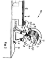
- the ejection station 28 comprises a chute 22, which with its one edge 36 almost engages into the opening 14 of the drum 11 and with its opposite bending edge 37 (cf. Fig. 2 ) is supported on the removal station 30, as well as a pivoting flap 29 located in the area of the bending edge 37.
- the slide 22 is arranged approximately plane-parallel to the roll-off track 17 or below the roll-off track and is slightly lowered relative to the roll-off track 17 so that the downhill rolling or sliding profiles of the guide device 18 fall directly onto the chute 22 and can be transported further.
- the removal station 30 is a belt conveyor or removal table which is an extension of the chute 22.
- the removal station 30 has a plurality of recesses 38 to be received by the profiles (rods 10).
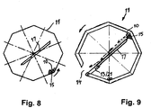
- FIGS. 8 and 9 show an alternative embodiment of a drum 11. Instead of a circular interior, this has a polygonal, in the illustrated embodiment: octagonal, contour. In this way, the alignment of the rods 10 on the base of the drum 11 can be promoted under certain operating conditions.
- a triangular driver contour is provided.
- round drums can also be equipped with triangular drivers or polygonal drums with round drivers.
- the design of the drum and driver contours depends on the respective application requirements.
- a bundle of rods 23 is loosely inserted and the unloaded drum 11 is set in rotation with the aid of a manually operated or remote-controlled electric drive.
- a V-trough or pre-separation can also be provided.
- the closure element 13 After a rotation of about 150 °, the closure element 13 automatically pivots as a result of gravity towards the interior of the drum 11 and releases the opening 14. First of all, a small opening gap is formed which, as the rotary movement continues (rotary phase b to rotary phase c), increases in size and finally opens the opening 14 completely.
- the drum is thus in the filling position P2 and the closure element 13 in the open position OP.
- the stock of bars in this filling position P2 in the through the opening 14 get into the drum 11. The bar material thus falls into the drum 11 and collects in its lower part.
- Rotation phase c also shows that the driver 15 is almost at its lowest position when the drum is in the filling position P2. Depending on the way in which the rods 10 fall into the drum 11, the driver 15 takes a rod 10 with it in the most favorable case. In the worst case, a rotation of 360 ° is required so that the driver 15 does not grasp the first rod 10 until the drum revolution following the filling.
- the driver 15 When the rotary movement continues from rotary phase d through rotary phase e in rotary phase f, the driver 15 first has its lowest position (detail "w" and Figure 5b ) taken, presses against the accumulated rods 10 and moves them in the direction of rotation F until the driver 15 assumes a position in which it is not able to hold all rods 10. Some rods 10 slide down over the driver 15, as shown in the detail "x" with the associated enlargement Figure 5c shows. At the same time, the closure element 13 has again moved from the closed position SP into the open position OP and is pivoted inward. A stop, not shown in more detail, limits the open position of the closure element 13.
- the closure element 13 having the notches 27 is pivoted maximally into the interior of the drum 11.
- the notches 26 of the closure element 13 and the notches 27 of the roll-off track 17 interlock, so that the closure element 13 roll-off track 17 jointly forms the already mentioned guide device 18 form.
- the last rod 10 held by the driver 15 up to this point can now also be moved from the driver 15 onto the guide device 18 and reaches the chute 22 via the opening 14.
- the closing element 13 is pressed down by its weight and by the bundle of rods into the closed position SP and closes the drum 11.
- a rod 10 is selected and conveyed out of the drum until the last rod 10 is also ejected from the rod layer 39 by the driver 10 onto the guide device 18.
Landscapes
- Engineering & Computer Science (AREA)
- Mechanical Engineering (AREA)
- Specific Conveyance Elements (AREA)
- Filling Or Emptying Of Bunkers, Hoppers, And Tanks (AREA)
Description
- Die Erfindung bezieht sich auf eine Vorrichtung zur Vereinzelung von lang gestreckten Profilen, wie beispielsweise Stangen, Drähten oder Rohren, umfassend
- eine drehbar gelagerte Trommel, an welchem wenigstens eine Öffnung vorgesehen ist,
- sowie wenigstens ein Verschlusselement, welches die Öffnung verschließt und freigibt,
- wenigstens einen an den Trommelmantel gekoppelten oder in den Trommelmantel integrierten Mitnehmer zur Selektion einer einzelnen Stange.
- Die Trommel der erfindungsgemäßen Vorrichtung weist einen Trommelmantel auf, der zylindrisch oder polygonal sein kann.
- Eine Selektion eines einzelnen Profils aus einer größeren Menge, beispielsweise einem Bund, ist erforderlich, wenn dieses Profil einzeln, beispielsweise auf einer Drehmaschine, bearbeitet werden soll.
- Aus
DE 20 29 304 C2 ist eine Vorrichtung zum Ausrichten, Trennen und einzeln Abgeben von länglichen Kleinteilen, mit einer um eine horizontale Achse drehbaren Schöpftrommel zur Aufnahme eines Vorratshaufens von Kleinteilen bekannt. Die Vorrichtung weist eine derartige Drehgeschwindigkeit auf, welche einem von der Trommel mitgerissenen Kleinteil eine Zentrifugalkraft erteilt, die größer ist als dessen Schwerkraft. Die Trommel weist im Inneren über mindestens einem Teil des Umfangs ein Profil auf, durch das die Kleinteile mit ihrer Längshauptrichtung auf die Längsausrichtung der Trommel ausgerichtet werden. - Am Grund des Profils ist eine als Schöpfelement für je ein Kleinteil dienende Vertiefung angeordnet, die, während sie unter dem Kleinteilhaufen durchläuft, ein Kleinteil aus dem Haufen aufnehmen kann. Die Vertiefung mündet in einen Kanal, der durch den Trommelmantel ungefähr tangential in Trommeldrehrichtung nach außen mündet. Die Vorrichtung verfügt über einen Verschluss für den Kanal. Nachteilig bei der bekannten Vorrichtung ist, dass sie lediglich für Werkstücke, wie Bolzen oder Schrauben vorgesehen ist und für längere Werkstücke, wie Profilstäbe auf Grund der ungünstigen Geometrie der Kanalmündung nicht geeignet ist.
- Solche Trommeln sind jedoch für die Selektion von Kleinteilen vorgesehen und zur Selektion langer Profile ungeeignet.
- Bei bekannten Vereinzelungsvorrichtung für langgestreckte Profile werden die Profile in einem Magazin beziehungsweise auf einem Lagerständer abgelegt und von dort über eine Zuführrutsche einzeln an eine nachgelagerte Bearbeitungsmaschine übergeben. Ebenfalls zur Selektion von Stangen- oder wellenförmigen Bauteilen kann ein sogenannter Pilgertisch oder eine Kammvereinzelung vorgesehen sein.
- Je dünner die Profile sind, desto eher verhaken sie jedoch ineinander und führen zu Störungen im Fertigungsprozess. Insbesondere wenn der Profildurchmesser kleiner als 10 mm ist, kann es zu Störungen im Ablauf kommen, die manuelle Eingriffe erfordern.
-
US 3 815 730 A offenbart eine Vorrichtung nach dem Oberbegriff des Anspruchs 1. - Es stellt sich daher die Aufgabe, eine neuartige Vorrichtung zu konzipieren, mit welcher die Vereinzelung von länglichen Profilelementen, wie Profilstäben oder Stangen, in einfacher Weise ermöglicht ist.
- Die vorgenannte Aufgabe ist mit einer Vorrichtung zur Vereinzelung von länglichen Profilen mit Merkmalen des Anspruchs 1 gelöst.
- Weitere technisch vorteilhafte Weiterbildungen sind in den Unteransprüchen beschrieben.
- Mit der Vorrichtung gemäß Erfindung sind Langprofile verschiedenster Art vereinzelbar. Bei den Profilen kann es sich um volle Rundstäbe oder -stangen oder um Mehrkantprofile handeln. Die Profile können auch dünne Werkstücke, wie Kapillarröhrchen oder Hohlnadel (Kanüle) für Einwegspritzen sein. Die zu vereinzelnden Langprofile werden im Folgenden auch als "Stangen" bezeichnet.
- In einer ersten Ausführungsform umfasst die Vereinzelungsvorrichtung eine drehbar gelagerte Trommel mit einem Innenraum und einem zylindrischen Trommelmantel, an welchem wenigstens eine Öffnung vorgesehen ist. Weiterhin ist wenigstens ein Verschlusselement vorgesehen, welches aus einer Schließposition in eine Offenposition bewegbar ist und die Öffnung verschließt und freigibt. Im Innenraum der Trommel ist wenigstens ein an den Trommelmantel gekoppelter Mitnehmer zur Selektion einer einzelnen Stange vorgesehen. Ein außerhalb der Trommel angeordneter Tragrahmen trägt eine in der Trommel befindliche, schräg gestellte Abrollbahn. Die Abrollbahn dreht sich somit bei Rotation der Trommel nicht mit, sondern behält vielmehr ihre Position im Innenraum der Trommel bei. Die Trommel ist in eine Auswurfposition drehbar, in welcher eine vom Mitnehmer selektierte Stange der Abrollbahn zuführbar ist, wobei das Verschlusselement sich in Offenposition befindet und gemeinsam mit der Abrollbahn eine Leiteinrichtung zum Auswurf der Stange durch die Öffnung der Trommel bildet.
- Die ortsfest angeordnete Abrollbahn kann - in längsaxialer Seitenansicht auf die Trommel - konvex, konkav, vorzugsweise eben sein. Als Abrollbahn soll grundsätzlich eine Fläche verstanden werden, über welche eine Stange bergab rollen und/oder gleiten kann.
- Die von der Vorrichtung vereinzelten Stangen werden vorzugsweise einer nachgeordneten weiteren Bearbeitungsmaschine, beispielsweise einer Drehmaschine, zugeführt. Besonders vorteilhaft ist, dass die im Innenraum der Trommel befindlichen Stangen, welche bei Rotation der Trommel schwerkraftbeding am tiefsten Punkt des Trommel-Innenraums angeordnet sind, sich durch die Rotation der Trommel in Längsrichtung ausrichten. Während bei im Stand der Technik bekannten Zuführrutschen ein auf der Zuführrutsche befindliches Stangenbündel kaum bewegt und sich einzelne Stangen des Bündels somit ineinander verhaken können, versetzt die Rotation der Trommel die Stangen am Trommelgrund in Bewegung, wodurch sich eventuell aneinander haftende Stangen voneinander lösen und sich in Längsrichtung ausrichten.
- Die Größe der Vorrichtung, insbesondere die Trommellänge bzw. Trommeldurchmesser kann in sehr großen Bereich variieren. So können die Trommeln eine Nutzlänge zwischen 0,05 Meter und 10 Meter, abhängig von der Länge des Stangenmaterials, aufweisen. Selbstverständlich können unterschiedliche Typengrößen der Trommel abhängig von den Ausmaßen des Stangenbündels vorgesehen sein. Kleinere Trommeln dienen zur Vereinzelung von sehr dünnen Stangen oder Kapillarröhrchen, größere Trommeln dienen in der Regel zur Selektion von Stangen mit größeren Durchmessern.
- Überraschenderweise sind die erfindungsgemäßen Vorrichtungen besonders gut zur Selektion von sehr dünnen, einen Durchmesser von weniger als 10mm aufweisenden, und gleichzeitig sehr langen, beispielsweise 6 Meter langen, Stangen geeignet. Ein bevorzugtes Einsatzgebiet der Vorrichtung ist deshalb dort angesiedelt, wo metallverarbeitende Betriebe aus von einem Stahlwerk zugelieferten 6-Meter-Stangenmaterial dünnwandige Kanülen herstellen. Selbstverständlich ist die erfindungsgemäße Vorrichtung nicht nur in der metallverarbeitenden Industrie, sondern auch in anderen Industriezweigen, beispielsweise zur Vereinzelung von Kunststoffstangen, einsetzbar.
- Die Stangen sind auf verschiedene Art und Weise entweder durch eine in einer Trommelseitenwand befindliche oder durch eine im Trommelmantel befindliche Öffnung in den Innenraum der Trommel förderbar. In einer bevorzugten Ausführung der Vorrichtung ist die Trommel in eine spezielle Befüllposition drehbar, in welcher eine oder mehrere Stangen bei in geöffnetem Verschlusselement durch die im Trommelmantel befindliche Öffnung in den Innenraum zuführbar sind. Die Befüllposition der Trommel kann in der oberen Hälfte, vorzugsweise - in Drehrichtung der Trommel gesehen - kurz vor dem Zenitbereich eines durch den Trommelumfang definierten Kreises liegen.
- Dieselbe Öffnung im Trommelmantel dient somit bei in Auswurfposition befindlicher Trommel zum Auswurf einzelner Stangen und bei in Befüllposition befindlicher Trommel zur Befüllung der Trommel. Um die Effizienz des Gesamtablaufs zu optimieren sind Befüll- und Auswurfposition der Trommel vorzugsweise um ca. 100° bis 180° versetzt zueinander angeordnet. Das heißt: Die Stangen gelangen von einer Seite in die Trommel hinein und einer im Wesentlichen gegenüberliegenden Seite aus der Trommel heraus. Das Stangen-Vorratslager ist dann beispielsweise hinter der Trommel und eine Vorrichtung zur Aufnahme der vereinzelten Stangen vor der Trommel angeordnet. Hierdurch ergibt sich ein raumsparender Aufbau der Gesamtmaschine.
- Der Leiteinrichtung, über welche die Stangen aus dem Trommelinnenraum herausgefördert werden, kann eine Wippe oder Rutsche nachgeschaltet sein. Die Wippe kann, bezogen auf eine längsaxiale Seitenansicht auf die Trommel, trog- bzw. V-förmig sein, wobei ihre Schwenkachse im tiefsten Punkt der Wippe liegt. In eine solche Wippe kann die einzelne Stange fallen und durch das Schwenken der Wippe weiter befördert werden. Vorzugsweise ist die Schwenkbewegung der Wippe mit der Drehbewegung der Trommel synchronisiert.
- Das Verschlusselement zum Verschließen der Trommel ist vorzugsweise als schwenkbare Öffnungsklappe ausgeführt, deren Schwenkachse mantellinienartig längs des Trommelmantels verläuft.
- Die Öffnungsklappe kann eben sein. Vorzugsweise ist sie jedoch an die Kontur der Trommel angepasst und stellt ein Segment des zylindrischen Trommelmantels dar.
- Vorzugsweise ist das Verschlusselement, beziehungsweise die Öffnungsklappe, nur ins Innere der Trommel schwenkbar. Die Schwenkbewegung nach außen kann durch entsprechende Gestaltung der aufeinanderstoßenden Längskanten der Öffnungsklappe und der Öffnung des Trommelmantels blockiert werden. Die Schwenkbewegung erfolgt vorzugsweise allein schwerkraftbedingt. Dies hat den Vorteil, dass zur Betätigung keine zusätzlichen Antriebe benötigt werden. Allerdings kann ein Antrieb für die Trommel vorgesehen sein um beispielsweise die Öffnungsgeschwindigkeit zu erhöhen.
- Oberhalb oder gegenüber der Auswurfposition der Trommel kann eine Beschickungsstation zur Aufnahme und Weitergabe einzelner Stangen oder eines Stangenbündels über die Öffnung in den Innenraum der Trommel angeordnet sein.
- Vorzugsweise umfasst die Beschickungsstation einen entlang der Trommel verlaufenden Trichter, eine Einfüllrutsche oder wenigstens eine seitlich begrenzte, entlang der Trommel verlaufende Leiste, so dass die Stangen allein durch die Schwerkraft in die Trommel fallen können. Zwei voneinander beabstandete Leisten können ein Vorratslager für die Stangen bilden.
- Die Beschickungsstation kann wenigstens ein verschiebbares oder schwenkbares Bodenelement umfassen, dessen Freigabe das Befüllen der Trommel beispielsweise mit einer Stangencharge ermöglicht.
- Bei dem Mitnehmer zur Selektion einer einzelnen Stange kann es sich um einen an eine Innenwand der Trommel befestigten Profilstab, beispielsweise einen drei- oder Vierkantstab, vorzugsweise einen Rundstab handeln.
- Der Mitnehmer zur Selektion einer einzelnen Stange ist vorzugsweise auswechselbar oder einstellbar, so dass bei Drehung der Trommel in Auswurfposition nur eine einzelne Stange vom Mitnehmer gehalten wird und andere zunächst vom Mitnehmer mitgenommener Stangen sich vor Erreichen der Auswurfposition vom Mitnehmer lösen.
- Darüber hinaus kann der Profilstab auch einen kombinierten, beispielsweise einen teils konkaven und teils runden Profilquerschnitt aufweisen. Dabei kann die einzelne Stange durch das konkave Teil des Profilstabes gehalten werden.
- Die Einstellbarkeit des Profilstabes kann durch seine Drehung bzw. Drehjustierung verwirklicht werden, falls der Profilstab an entsprechenden, an der Innenwand der Trommel angeordneten jochartigen Halterungen gehalten ist. Es kann aber auch eine Haltevorrichtung für den Profilstab vorgesehen sein, mittels derer die Höhe und/oder die Ausrichtung des Profilstabes einstellbar ist.
- Der Mitnehmer zur Selektion der Stangen kann auch in einem Materialstück zusammen mit der Trommel ausgeführt sein. Dies betrifft insbesondere Trommeln, die grundsätzlich lediglich eine bestimmte Sorte von Profilen selektieren sollen und bei denen insofern ein Umrüsten auf andere Profile nicht erforderlich ist.
- Die freie Längskante der Öffnungsklappe und/oder wenigstens die schräg nach unten zeigende Kante der Abrollbahn können so gestaltet sein, dass sie sich miteinander verzahnen bzw. ineinander greifen, so dass sie in der als Auswurfposition vorgesehene Lage der Trommel eine gemeinsame Fläche, beziehungsweise Abrollbahn und damit eine Leiteinrichtung für eine aus der Trommel herausrollende Stange bilden.
- Zu diesem Zweck können die Öffnungsklappe zum Verschließen des Trommelmantels und die Abrollbahn im Inneren der Trommel wenigstens teilweise kammartig ausgebildet sein. Durch die ineinandergreifenden kammartigen Strukturen wird vermieden, dass in Auswurfposition ein Spalt zwischen Abrollbahn und Öffnungsklappe verbleibt, durch den dünne Profile hindurchfallen oder in dem sie sich beim herausrollen verhaken könnten.
- Die Trommel kann zum Zwecke der Gewichtsenkung und zur Entfernung von Schmutzpartikeln wenigstens teilweise sieb- oder gitterartig ausgebildet bzw. perforiert sein, so dass die Schmutzpartikel und/oder andere unerwünschten Kleinteile über die bestehenden Maschen nach außen gelangen und Reinigungsarbeiten in der Trommel ersparen können. Die Trommel kann somit auch gleichzeitig als Waschtrommel genutzt werden.
- Die Trommel kann zusätzlich zu der bereits beschriebenen Elementen, nämlich der Öffnung, dem Verschlusselement und dem Mitnehmer, wenigstens eine weitere Öffnung, ein weiteres Verschlusselement und einen weiteren Mitnehmer umfassen, welche so angeordnet sind, dass bei einer Umdrehung der Trommel nach Selektion einer ersten Stange wenigstens eine weitere Stange selektierbar ist. Die Vorrichtung kann somit eine oder mehrere, beispielsweise zwei oder drei gleichmäßig am Trommelmantel verteilte Öffnungen zum Befüllen und Auswerfen von Profilen umfassen, welche jeweils mit einem Verschlusselement zu öffnen und zu verschließen sind. So können beispielsweise nacheinander zwei Profile bei der Drehung jeweils um 1800 oder drei Profile bei der Drehung jeweils um 1200 ausgeworfen werden.
- Die Erfindung wird nachstehend als Beispiel beschrieben und in den Figuren dargestellt. Die Figuren zeigen:
- Fig. 1
- eine Vorrichtung gemäß Erfindung in einer perspektivischen Ansicht;
- Fig. 2
- die Vorrichtung gemäß
Fig. 1 in einer perspektivischen Schnittdarstellung mit Blick in den Innenraum der Trommel; - Fig. 3
- die Vorrichtung gemäß
Fig. 1 in einer Seitenansicht in Schnittdarstellung; - Fig. 4
- die schematische Darstellung einer Trommelrotation mit Darstellung der Trommel in acht Drehpositionen a bis h und hiermit verbundener Vereinzelung einer einzelnen Stange;
- Fig. 5a bis 5e:
- die Vereinzelung einer Stange in vergrößerten Detailansichten "v", "w", "x", "y", "z" gemäß
Fig. 4 ; - Fig. 6
- eine Trommel in einer perspektivischen Ansicht;
- Fig. 7
- eine vergrößerte Darstellung der in
Fig. 4 gezeigten Trommelposition h; - Fig. 8
- eine schematische Darstellung einer alternativen Ausführungsform mit einer Vieleck-Trommel;
- Fig. 9
- die Vielecktrommel gemäß
Fig. 8 in Auswurfposition. - Gleiche oder ähnliche Elemente können in den nachfolgenden Figuren mit gleichen oder ähnlichen Bezugszeichen versehen sein. Ferner enthalten die Figuren der Zeichnung, deren Beschreibung sowie die Ansprüche zahlreiche Merkmale in Kombination. Einem Fachmann ist dabei klar, dass diese Merkmale auch einzeln betrachtet werden oder sie zu weiteren, hier nicht näher beschriebenen Kombinationen zusammengeführt werden können.
- Eine in den
Figuren 1 ,2 und3 dargestellte Vorrichtung 100 zur Vereinzelung von länglichen Profilen oder Werkstücken, die im Folgenden als Stangen 10 bezeichnet werden, setzt sich im Wesentlichen aus folgenden Teilen zusammen: - einem Tragrahmen 16,
- einer an dem Tragrahmen 16 waagerecht gelagerten Trommel 11 mit einem Innenraum 40 und einem Trommelmantel 12, an welchem eine Öffnung 14 eingebracht ist,
- einer innerhalb der Trommel 11 schräg angeordneten Abrollbahn 17, welche am Tragrahmen 16 ortsfest angebracht ist und bei Rotation der Trommel (10) nicht mitrotiert,
- einem Verschlusselement 13,
- einer Beschickungsstation 20,
- einer Auswurfstation 28,
- und einer Entnahmestation 30.
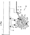
- Der Tragrahmen 16 umfasst zwei seitliche Deckel 31, 31', welche jeweils mit einem Gestell 32 verbunden sind. Die beiden Gestelle 32 ruhen auf einem Podest 33. Die seitlichen Deckel 31, 31' umfassen zusätzliche Deckelteile. In
Figur 1 sind die zusätzlichen Deckelteile 31'a und 31'b des Deckels 31' sichtbar. Auch der Deckel 31 hat entsprechende Deckelteile, die aber inFigur 1 verdeckt sind. Mittels der zusätzlichen Deckelteile kann die Position und die Neigung der Abrollbahn 17 variiert werden. - Die Trommel 11 besteht aus einer Vielzahl von voneinander beabstandeten und an Befestigungsleisten 35 aufgereihten Flachringen 34 (vgl.
Fig. 6 ), welche einen tubusartigen Hohlkörper bilden, an dessen Innenwand 25 ein sich über die ganze Trommellänge erstreckender, rundstabförmiger Mitnehmer 15 befestigt ist. Hierdurch erhält die Trommel eine siebartige Struktur. Darüber hinaus lässt sich bei Herstellung der Trommel 11 durch die Anzahl oder den Abstand der aufgereihten Flachringen 34 die Trommellänge einfach variieren. - Das Verschlusselement 13 ist als Teilbereich des Trommelmantels 12 ausgebildet und verschließt in Schließposition SP den Innenraum 40. In Offenposition OP gibt das Verschlusselement 13 die Öffnung 14 frei. Der Wechsel des Verschlusselements 13 aus der Offenposition OP in die Schließposition SP und umgekehrt erfolgt im dargestellten Ausführungsbeispiel bei Drehung der Trommel 11 schwerkraftbedingt und ohne zusätzlichen Antrieb (vgl.
Figuren 4 ,6 und 7 ). Alternativ oder ergänzend zu einem schwerkraftbedingten Wechsel von Offenposition und Schließposition kann aber auch ein separater Antrieb vorgesehen zu sein um beispielsweise das Öffnen und Schließen in anderen Drehpositionen der Trommel oder mit größerer Geschwindigkeit zu ermöglichen. - Das Verschlusselement 13 ist in Form einer um eine Schwenkachse 19 drehbaren und sich ebenso über die ganze Trommellänge erstreckenden Öffnungsklappe 21 ausgeführt. Das Öffnen und Schließen der Öffnungsklappe 21 erfolgt im dargestellten Ausführungsbeispiel auf Schwerkraftbasis, das heißt: zur Betätigung der Öffnungsklappe 21 ist kein zusätzlicher Antrieb erforderlich.
- Die Beschickungsstation 20 in ihrer einfachsten Form wird durch eine bzw. zwei seitlich begrenzte Leisten 24 ausgebildet, welche eine Charge (Stangenbündel 23, vgl.
Fig. 3 ) aufnehmen können. Die Leisten 24 sind an den Deckeln 31, 31' derart befestigt, dass sie über den Trommelmantel 12 gleiten. Trifft die Öffnung 14 - bei der Drehung der Trommel 11 - auf die Beschickungsstation 20, fällt automatisch, schwerkraftbedingt das ganze Stangenbündel 23 über diese Öffnung 14 in die Trommel 11 hinein. Alternativ zur dargestellten Beschickungsstation 20 sind auch andere Beschickungseinrichtung einsetzbar. - Im dargestellten Ausführungsbeispiel weist die innerhalb der Trommel 11 liegende Abrollbahn 17 mehrere in Richtung der Auswurfstation 28 zeigende, kammartige Spalten oder Einkerbungen 26 auf, welche - bei dem in einer Auswurfposition P1 (vgl.
Fig. 7 ) befindlichen Verschlusselement 13 - mit entsprechenden Einkerbungen 27 des Verschlusselementes 13 (Öffnungsklappe 21) ineinandergreifen und damit eine Leiteinrichtung 18 zum Auswurf einer vereinzelten Stange 10 durch die Öffnung 14 bilden. - Die Auswurfstation 28 umfasst eine Rutsche 22, welche mit ihrer einen Kante 36 nahezu in die Öffnung 14 der Trommel 11 greift und sich mit ihrer gegenüber liegenden Biegekante 37 (vgl.
Fig. 2 ) an der Entnahmestation 30 abstützt, sowie eine im Bereich der Biegekante 37 liegende Schwenkklappe 29. Die Rutsche 22 ist etwa planparallel zur Abrollbahn 17 oder unterhalb der Abrollbahn angeordnet und ist gegenüber der Abrollbahn 17 etwas abgesenkt, so dass die bergab rollenden oder gleitenden Profile von der Leiteinrichtung 18 direkt auf die Rutsche 22 fallen und weiter befördert werden können. - Bei der Entnahmestation 30 handelt es sich um einen Bandförderer oder Entnahmetisch, welcher eine Verlängerung der Rutsche 22 darstellt. Im vorliegenden Fall weist die Entnahmestation 30 eine Vielzahl von die Profile (Stangen 10) aufzunehmenden Vertiefungen 38 auf.
- Die
Figuren 8 und 9 zeigen eine alternative Ausführung einer Trommel 11. Diese weist an Stelle eines kreisrunden Innenraums eine vieleckige, im dargestellten Ausführungsbeispiel: achteckige, Kontur auf. Hierdurch kann bei bestimmten Einsatzbedingungen das Ausrichten der Stangen 10 am Grund der Trommel 11 begünstigt werden. - Als Beispiel für eine andere Profilierung eines Mitnehmers 15 ist eine dreieckige Mitnehmerkontur vorgesehen. Selbstverständlich können auch runde Trommeln mit dreieckigen Mitnehmern oder vieleckige Trommel mit runden Mitnehmern ausgerüstet werden. Die konstruktive Ausgestaltung von Trommel- und Mitnehmerkontur erfolgt in Abhängigkeit von den jeweiligen Einsatzanforderungen.
- Bei der Funktionsbeschreibung wird nur eine Charge berücksichtigt.
- In die Beschickungsstation 20 (vgl.
Fig. 3 ) wird ein Stangenbündel 23 lose eingelegt und die unbeladene Trommel 11 mit Hilfe eines manuell betätigbaren oder ferngesteuerten Elektroantriebs in Drehung versetzt. Alternativ hierzu kann auch eine V-Mulde oder eine Vorvereinzelung vorgesehen sein. - Mit dem Pfeil F ist die Drehrichtung der Trommel 11 bezeichnet. Das Verschlusselement 13 befindet sich in einer Schließposition SP. Dieser Zustand entspricht der
Fig. 4 (Drehphase a). - Nach einer Drehung um etwa 150° schwenkt das Verschlusselement 13 automatisch infolge der Schwerkraft zum Inneren der Trommel 11 und gibt die Öffnung 14 frei. Zunächst bildet sich ein kleiner Öffnungsspalt, der sich bei fortgesetzter Drehbewegung (Drehphase b zu Drehphase c) zunehmend vergrößert und schließlich die Öffnung 14 komplett freigibt. Die Trommel befindet sich somit in Befüllposition P2 und das Verschlusselement 13 in Offenposition OP. Soweit die Beschickungsstation 20 mit einem Stangenvorrat belegt ist, kann der Stangevorrat in dieser Befüllposition P2 in den durch die Öffnung 14 in die Trommel 11 gelangen. Das Stangenmaterial fällt somit in die Trommel 11 hinein und sammelt sich in ihrem unteren Teil.
- Drehphase c zeigt weiterhin, dass der Mitnehmer 15 sich bei in Befüllposition P2 befindlicher Trommel nahezu an seiner tiefsten Position befindet. In Abhängigkeit von der Art und Weise, wie die Stangen 10 in die Trommel 11 hineinfallen, nimmt der Mitnehmer 15 im günstigen Fall eine Stange 10 unmittelbar mit. Im ungünstigen Fall ist eine Umdrehung um 360° erforderlich, so dass der Mitnehmer 15 die erste Stange 10 erst bei dem der Befüllung nachfolgenden Trommelumlauf erfasst.
- Diese Situation ist in Drehphase 4d dargestellt. Die Trommel 11 hat sich um 360° gedreht. Das Verschlusselement 13 befindet sich in Schließposition SP. Die Trommel 11 ist jedoch beladen, wie es das Detail "v" und seine Vergrößerung gemäß
Fig. 5a zeigen. Der Mitnehmer 15 erreicht nahezu eine Zenitlage und hat keinen Kontakt mit den Stangen 10. - Bei Fortsetzung der Drehbewegung von Drehphase d über Drehphase e in Drehphase f hat der Mitnehmer 15 zuerst seine unterste Lage (Detail "w" und
Fig. 5b ) eingenommen, drückt gegen die angesammelten Stangen 10 und bewegt diese in Drehrichtung F, bis der Mitnehmer 15 eine Lage einnimmt, bei der er nicht alle Stangen 10 zu halten vermag. Einige Stangen 10 fallen gleitend über den Mitnehmer 15 nach unten, wie es das Detail "x" mit zugehöriger Vergrößerung gemäßFig. 5c zeigt. Gleichzeitig hat sich das Verschlusselement 13 wiederum aus der Schließposition SP in die Offenposition OP bewegt und ist nach innen verschwenkt. Ein nicht näher dargestellter Anschlag begrenzt die Offenposition des Verschlusselementes 13. - Bei einer weiteren Drehung werden zunächst noch drei Stangen 10 vom Mitnehmer 15 gehalten (Drehphasen g,
Fig. 5d ). Der Mitnehmer 15 ist so dimensioniert, dass bis zum Erreichen der Auswurfposition P1 alle Stangen 10 bis auf die zu selektierende letzte Stange 10 wieder zurück auf den Trommelboden fallen. In Auswurfposition P1 wird somit nur noch eine Stange 10 vom Mitnehmer 15 gehalten, wie es die Details "y" (Drehphase g) und "z" (Drehphase h) undFigur 5e zeigen. Die restlichen Stangen 10 bilden eine unten liegende Stangenschicht 39 aus. - In Drehphase h ist das die Einkerbungen 27 aufweisende Verschlusselement 13 maximal ins Innere der Trommel 11 geschwenkt. Die Einkerbungen 26 des Verschlusselements 13 und die Einkerbungen 27 der Abrollbahn 17 greifen ineinander, so dass Verschlusselement 13 Abrollbahn 17 gemeinsam die bereits erwähnte Leiteinrichtung 18 ausbilden. In Auswurfposition P1 kann nunmehr auch die letzte vom Mitnehmer 15 bis hierher gehaltene Stange 10 vom Mitnehmer 15 ab auf die Leiteinrichtung 18 und gelangt über die Öffnung 14 auf die Rutsche 22.
- Bei Fortsetzung der Drehbewegung wird das Verschlusselement 13 durch seine Gewichtskraft und durch das Stangenbündel in die Schließposition SP heruntergedrückt und schließt die Trommel 11.
- Nachfolgend wird bei jeder weiteren Trommelumdrehung eine Stange 10 selektiert und aus der Trommel herausgefördert bis auch die letzte Stange 10 aus der Stangenschicht 39 durch den Mitnehmer 10 auf die Leiteinrichtung 18 ausgeworfen ist.
- Bei Bedarf und zur Sicherung eines kontinuierlichen Prozesses kann zwischenzeitlich jedoch neues Stangenmaterial über die Beschickungsstation 20 zugeführt werden. Hierdurch kann ein insgesamt kontinuierlicher Prozess sichergestellt werden.
Bezugszeichenliste: 10 Profil (Stange) 34 Flachring 11 Trommel 35 Befestigungsleiste ( Fig. 6 )12 Trommelmantel 36 Kante (von 22) 13 Verschlusselement 37 Biegekante (von 22) 14 Öffnung 38 Vertiefung 15 Mitnehmer 39 Stangenschicht 16 Tragrahmen 40 Innenraum (von 11) 17 Abrollbahn 18 Leiteinrichtung 100 Vorrichtung 19 Schwenkachse 20 Beschickungsstation a bis h Drehphase der Trommel 21 Öffnungsklappe 22 Rutsche F Pfeil (Drehrichtung) 23 Stangenbündel 24 Leiste P1 Auswurfposition (der Trommel) 25 Innenwand P2 Befüllposition (der Trommel) 26 Einkerbungen SP Schließposition (von 13) 27 Einkerbungen OP Offenposition (von 13) 28 Auswurfstation V Vertikalachse 29 Schwenkklappe 30 Entnahmestation 31, 31' Deckel 31'a Deckelteil 31'b Deckelteil 32 Gestell 33 Podest
Claims (13)
- Vorrichtung (100) zur Vereinzelung von lang gestreckten Profilen, wie Stangen (10), umfassend- eine drehbar gelagerte Trommel (11) mit einem Innenraum (40) und einem zylindrischen oder polygonalen Trommelmantel (12), an welchem wenigstens eine Öffnung (14) vorgesehen ist,- sowie wenigstens ein Verschlusselement (13), welches aus einer Schließposition (SP) in eine Offenposition (OP) bewegbar ist und die Öffnung (14) verschließt und freigibt,- wenigstens einen an den Trommelmantel (12) gekoppelten oder in den Trommelmantel (12) integrierten Mitnehmer (15) zur Selektion einer einzelnen Stange (10),wobei ein außerhalb der Trommel (11) angeordneter Tragrahmen (16) vorgesehen ist, welcher eine in der Trommel (11) befindliche, schräg gestellte Abrollbahn (17) trägt und die Trommel (11) in eine Auswurfposition (P1) drehbar ist, in welcher eine vom Mitnehmer (15) selektierte Stange (10) der Abrollbahn (17) zuführbar ist,
dadurch gekennzeichnet, dass das Verschlusselement (13) sich in Offenposition (OP) befindet und gemeinsam mit der Abrollbahn (17) eine Leiteinrichtung (18) zum Auswurf der Stange (10) durch die Öffnung (14) bildet. - Vorrichtung (100) nach Anspruch 1, dadurch gekennzeichnet, dass die Trommel (11) in eine Befüllposition (P2) drehbar ist, in welcher eine oder mehrere Stangen (10) bei in Offenposition (OP) befindlichem Verschlusselement (13) durch die Öffnung (14) in den Innenraum (40) zuführbar sind.
- Vorrichtung (100) nach einem der Ansprüche 1 oder 2, dadurch gekennzeichnet, dass der Leiteinrichtung (18) eine Wippe oder Rutsche (22) oder ein anderes Fördermittel nachgeschaltet ist.
- Vorrichtung (100) nach einem der Ansprüche 1 bis 3, dadurch gekennzeichnet, dass das Verschlusselement (13) als schwenkbare Öffnungsklappe (21) ausgeführt ist, deren Schwenkachse (19) mantellinienartig längs des Trommelmantels (12) verläuft.
- Vorrichtung (100) nach einem der Ansprüche 1 bis 4, dadurch gekennzeichnet, dass an oder oberhalb der Trommel (11) eine Beschickungsstation (20) zur Aufnahme und Weitergabe einzelner Stangen (10) oder eines Stangenbündels (23) über die Öffnung (14) in den Innenraum (40) der Trommel (11) angeordnet ist.
- Vorrichtung (100) nach Anspruch 5, dadurch gekennzeichnet, dass die Beschickungsstation (20) einen entlang der Trommel (11) verlaufenden Trichter, eine Einfüllrutsche oder wenigstens eine seitlich begrenzte Leiste (24) umfasst.
- Vorrichtung (100) nach einem der Ansprüche 1 bis 6, dadurch gekennzeichnet, dass der Mitnehmer (15) zur Selektion einer einzelnen Stange (10) ein an eine Innenwand (25) der Trommel (11) befestigter Profilstab, wie Drei- oder Vierkantstab, vorzugsweise ein Rundstab ist.
- Vorrichtung (100) nach einem der Ansprüche 1 bis 7, dadurch gekennzeichnet, dass der Mitnehmer (15) zur Selektion einer einzelnen Stange (10) auswechselbar oder einstellbar ist, so dass bei Drehung der Trommel (11) in Auswurfposition (P1) nur eine einzelne Stange (10) vom Mitnehmer (15) gehalten wird und andere zunächst vom Mitnehmer (15) mitgenommenen Stangen (10) sich vor Erreichen der Auswurfposition (P1) vom Mitnehmer (15) lösen.
- Vorrichtung (100) nach einem der Ansprüche 1 bis 7, dadurch gekennzeichnet, dass der Mitnehmer (15) zur Selektion der Stangen (10) in einem Materialstück zusammen mit der Trommel (11) ausgeführt ist.
- Vorrichtung (100) nach einem der Ansprüche 1 bis 9, dadurch gekennzeichnet, dass die Trommel (11) und/oder die Öffnungsklappe (21) und/oder die Abrollbahn (17) wenigstens teilweise kammartig ausgebildet ist.
- Vorrichtung (100) nach Anspruch 10, dadurch gekennzeichnet, dass die Abrollbahn (17) und die Öffnungsklappe (21) - in der Auswurfposition (P1) und/oder in der Befüllposition (P2) der Trommel (11) - mit ihren kammartigen Einkerbungen (26; 27) ineinandergreifen.
- Vorrichtung (100) nach einem der Ansprüche 1 bis 11, dadurch gekennzeichnet, dass die Trommel (11) wenigstens teilweise sieb- oder gitterartig ausgebildet bzw. perforiert sein kann.
- Vorrichtung (100) nach einem der Ansprüche 1 bis 12, dadurch gekennzeichnet, dass die Trommel zusätzlich zu Öffnung (14), dem Verschlusselement (13) und dem Mitnehmer (15) wenigstens eine weitere Öffnung, ein weiteres Verschlusselement und einen weiteren Mitnehmer umfasst, die so angeordnet sind, dass bei einer Umdrehung der Trommel (11) nach Selektion einer ersten Stange (10) wenigstens eine weitere Stange (10) selektierbar ist.
Priority Applications (1)
| Application Number | Priority Date | Filing Date | Title |
|---|---|---|---|
| PL19167117T PL3552993T3 (pl) | 2018-04-12 | 2019-04-03 | Urządzenie rozdzielające |
Applications Claiming Priority (1)
| Application Number | Priority Date | Filing Date | Title |
|---|---|---|---|
| DE102018108730.6A DE102018108730A1 (de) | 2018-04-12 | 2018-04-12 | Vereinzelungsmaschine |
Publications (2)
| Publication Number | Publication Date |
|---|---|
| EP3552993A1 EP3552993A1 (de) | 2019-10-16 |
| EP3552993B1 true EP3552993B1 (de) | 2020-12-16 |
Family
ID=66092088
Family Applications (1)
| Application Number | Title | Priority Date | Filing Date |
|---|---|---|---|
| EP19167117.1A Not-in-force EP3552993B1 (de) | 2018-04-12 | 2019-04-03 | Vereinzelungsmaschine |
Country Status (4)
| Country | Link |
|---|---|
| EP (1) | EP3552993B1 (de) |
| DE (1) | DE102018108730A1 (de) |
| ES (1) | ES2857960T3 (de) |
| PL (1) | PL3552993T3 (de) |
Families Citing this family (3)
| Publication number | Priority date | Publication date | Assignee | Title |
|---|---|---|---|---|
| CN112607446A (zh) * | 2020-11-24 | 2021-04-06 | 洛阳兰迪玻璃机器股份有限公司 | 一种支撑物自动排序机构、支撑物分离装置及其布放系统 |
| CN116692452A (zh) * | 2023-07-17 | 2023-09-05 | 马鞍山石冶机械制造有限公司 | 一种管件加工上料装置 |
| CN117184828B (zh) * | 2023-09-08 | 2026-01-13 | 千年舟新材科技集团股份有限公司 | 筒状物高效定向输送装置 |
Family Cites Families (8)
| Publication number | Priority date | Publication date | Assignee | Title |
|---|---|---|---|---|
| BE470115A (de) * | ||||
| US3815730A (en) * | 1972-08-02 | 1974-06-11 | T Zwiep | Orienting apparatus and method |
| US5011024A (en) * | 1989-10-23 | 1991-04-30 | Bunney Leroy R | Rotary log sorter |
| JPH08198434A (ja) * | 1995-01-30 | 1996-08-06 | Yuyama Seisakusho:Kk | 薬剤の払出し方法およびその装置 |
| DE19637109C1 (de) * | 1996-09-12 | 1997-11-13 | Freudenberg Carl Fa | Fördervorrichtung |
| JP2004182456A (ja) * | 2002-12-06 | 2004-07-02 | Murata Mfg Co Ltd | チップ部品の整列供給装置 |
| DE102006018254A1 (de) * | 2006-04-20 | 2007-10-25 | Häfner, Jochen, Dipl.-Ing. | Trommelfördersilo |
| DE102008026883B4 (de) * | 2008-06-05 | 2018-09-27 | Johnson & Johnson Gmbh | Trommel für ein System, System und Verfahren zum Ausrichten, Sortieren und/oder Ordnen von chaotisch zueinander liegenden Gegenständen |
-
2018
- 2018-04-12 DE DE102018108730.6A patent/DE102018108730A1/de not_active Withdrawn
-
2019
- 2019-04-03 ES ES19167117T patent/ES2857960T3/es active Active
- 2019-04-03 PL PL19167117T patent/PL3552993T3/pl unknown
- 2019-04-03 EP EP19167117.1A patent/EP3552993B1/de not_active Not-in-force
Non-Patent Citations (1)
| Title |
|---|
| None * |
Also Published As
| Publication number | Publication date |
|---|---|
| ES2857960T3 (es) | 2021-09-29 |
| DE102018108730A1 (de) | 2019-10-17 |
| PL3552993T3 (pl) | 2021-07-19 |
| EP3552993A1 (de) | 2019-10-16 |
Similar Documents
| Publication | Publication Date | Title |
|---|---|---|
| DE69300354T2 (de) | Einrichtung zum automatischen Positionieren und Ausrichten von Behältern. | |
| DE2747866C2 (de) | Vorrichtung zum Ausstreuen von Saatgut | |
| EP3552993B1 (de) | Vereinzelungsmaschine | |
| DE102013215233A1 (de) | Beladeteller einer Beschickungsanlage für eine Verpackungsmaschine für Süßwaren | |
| DE2031286C2 (de) | Vorrichtung zum Herstellen eines Leuchtschirms | |
| EP2130445B1 (de) | Vorrichtung und Verfahren zum aufeinander folgenden Entleeren von mit stabförmigen Produkten gefüllten Behältern | |
| EP2762034B1 (de) | Puffer für Bürsten | |
| EP1022821B1 (de) | Verfahren und Einrichtung zur Tüllenbestückung | |
| DE6610240U (de) | Vorrichtung zum entladen von zigarettenschragen od. dgl. behaeltern. | |
| DE2437795A1 (de) | Vorrichtung zum entladen von dosen oder dgl. rohrfoermigen behaeltern | |
| EP1671903B1 (de) | Vorrichtung zum vereinzelten Weitertransport von leichten Kleinteilen, wie insbesondere von Tabletten | |
| AT410204B (de) | Einrichtung zum vereinzeln und ausschleusen von in einer reihe auf einer rollenbahn abgelegten stückgütern | |
| DE4118883A1 (de) | Vorrichtung zum abreibenden und entstaubenden handling von losen schuettguetern, insbesondere zum entgraten und entstauben von aus einer tablettenpresse zugefuehrten tabletten oder pillen nach dem pressvorgang | |
| DE2629634A1 (de) | Vorrichtung zum trennen und ordnen von muenzen u.dgl. | |
| DE2458394A1 (de) | Vorrichtung zum transportieren einer vorbestimmten anzahl gegenstaende sowie verwendung einer solchen vorrichtung | |
| DE202018101996U1 (de) | Vereinzelungsmaschine | |
| DE3321173C2 (de) | ||
| DE69008323T2 (de) | Pflanzensetzmaschine. | |
| DE4425522C2 (de) | Band-Zellenausleser zum Separieren fließfähiger Schüttgüter | |
| DE29803676U1 (de) | Metallfördereinrichtung | |
| DE19704421B4 (de) | Vorrichtung zur Bildung von Bunden aus Walzdrahtschlingen | |
| DE2729885B2 (de) | Vorrichtung zum Vereinzeln und Ausrichten gleichartiger, einendig geschlossener, hohler Werkstücke, wie Kartuschhülsen o.dgl | |
| DE2520685C3 (de) | Vorrichtung zum Zählen und dosierten Abfüllen von Tabletten, Dragees, Gelatinekapseln u.dgl. Körpern | |
| DE2659287A1 (de) | Einrichtung zur ausrichtung von gegenstaenden | |
| DE2550987A1 (de) | Vorrichtung zum zaehlen und dosierten abfuellen von tabletten, dragees, gelatinekapseln u.dgl. koerpern |
Legal Events
| Date | Code | Title | Description |
|---|---|---|---|
| PUAI | Public reference made under article 153(3) epc to a published international application that has entered the european phase |
Free format text: ORIGINAL CODE: 0009012 |
|
| STAA | Information on the status of an ep patent application or granted ep patent |
Free format text: STATUS: THE APPLICATION HAS BEEN PUBLISHED |
|
| AK | Designated contracting states |
Kind code of ref document: A1 Designated state(s): AL AT BE BG CH CY CZ DE DK EE ES FI FR GB GR HR HU IE IS IT LI LT LU LV MC MK MT NL NO PL PT RO RS SE SI SK SM TR |
|
| AX | Request for extension of the european patent |
Extension state: BA ME |
|
| STAA | Information on the status of an ep patent application or granted ep patent |
Free format text: STATUS: REQUEST FOR EXAMINATION WAS MADE |
|
| 17P | Request for examination filed |
Effective date: 20200211 |
|
| RBV | Designated contracting states (corrected) |
Designated state(s): AL AT BE BG CH CY CZ DE DK EE ES FI FR GB GR HR HU IE IS IT LI LT LU LV MC MK MT NL NO PL PT RO RS SE SI SK SM TR |
|
| GRAP | Despatch of communication of intention to grant a patent |
Free format text: ORIGINAL CODE: EPIDOSNIGR1 |
|
| STAA | Information on the status of an ep patent application or granted ep patent |
Free format text: STATUS: GRANT OF PATENT IS INTENDED |
|
| RIC1 | Information provided on ipc code assigned before grant |
Ipc: B65G 47/14 20060101AFI20200619BHEP |
|
| INTG | Intention to grant announced |
Effective date: 20200721 |
|
| GRAS | Grant fee paid |
Free format text: ORIGINAL CODE: EPIDOSNIGR3 |
|
| GRAA | (expected) grant |
Free format text: ORIGINAL CODE: 0009210 |
|
| STAA | Information on the status of an ep patent application or granted ep patent |
Free format text: STATUS: THE PATENT HAS BEEN GRANTED |
|
| AK | Designated contracting states |
Kind code of ref document: B1 Designated state(s): AL AT BE BG CH CY CZ DE DK EE ES FI FR GB GR HR HU IE IS IT LI LT LU LV MC MK MT NL NO PL PT RO RS SE SI SK SM TR |
|
| REG | Reference to a national code |
Ref country code: GB Ref legal event code: FG4D Free format text: NOT ENGLISH |
|
| REG | Reference to a national code |
Ref country code: IE Ref legal event code: FG4D Free format text: LANGUAGE OF EP DOCUMENT: GERMAN |
|
| REG | Reference to a national code |
Ref country code: DE Ref legal event code: R096 Ref document number: 502019000526 Country of ref document: DE |
|
| REG | Reference to a national code |
Ref country code: AT Ref legal event code: REF Ref document number: 1345400 Country of ref document: AT Kind code of ref document: T Effective date: 20210115 |
|
| REG | Reference to a national code |
Ref country code: CH Ref legal event code: NV Representative=s name: R.A. EGLI AND CO, PATENTANWAELTE, CH |
|
| REG | Reference to a national code |
Ref country code: NL Ref legal event code: FP |
|
| PG25 | Lapsed in a contracting state [announced via postgrant information from national office to epo] |
Ref country code: NO Free format text: LAPSE BECAUSE OF FAILURE TO SUBMIT A TRANSLATION OF THE DESCRIPTION OR TO PAY THE FEE WITHIN THE PRESCRIBED TIME-LIMIT Effective date: 20210316 Ref country code: GR Free format text: LAPSE BECAUSE OF FAILURE TO SUBMIT A TRANSLATION OF THE DESCRIPTION OR TO PAY THE FEE WITHIN THE PRESCRIBED TIME-LIMIT Effective date: 20210317 Ref country code: FI Free format text: LAPSE BECAUSE OF FAILURE TO SUBMIT A TRANSLATION OF THE DESCRIPTION OR TO PAY THE FEE WITHIN THE PRESCRIBED TIME-LIMIT Effective date: 20201216 Ref country code: RS Free format text: LAPSE BECAUSE OF FAILURE TO SUBMIT A TRANSLATION OF THE DESCRIPTION OR TO PAY THE FEE WITHIN THE PRESCRIBED TIME-LIMIT Effective date: 20201216 |
|
| PGFP | Annual fee paid to national office [announced via postgrant information from national office to epo] |
Ref country code: FR Payment date: 20210225 Year of fee payment: 3 Ref country code: CZ Payment date: 20210317 Year of fee payment: 3 |
|
| PG25 | Lapsed in a contracting state [announced via postgrant information from national office to epo] |
Ref country code: LV Free format text: LAPSE BECAUSE OF FAILURE TO SUBMIT A TRANSLATION OF THE DESCRIPTION OR TO PAY THE FEE WITHIN THE PRESCRIBED TIME-LIMIT Effective date: 20201216 Ref country code: SE Free format text: LAPSE BECAUSE OF FAILURE TO SUBMIT A TRANSLATION OF THE DESCRIPTION OR TO PAY THE FEE WITHIN THE PRESCRIBED TIME-LIMIT Effective date: 20201216 Ref country code: BG Free format text: LAPSE BECAUSE OF FAILURE TO SUBMIT A TRANSLATION OF THE DESCRIPTION OR TO PAY THE FEE WITHIN THE PRESCRIBED TIME-LIMIT Effective date: 20210316 |
|
| PGFP | Annual fee paid to national office [announced via postgrant information from national office to epo] |
Ref country code: TR Payment date: 20210326 Year of fee payment: 3 |
|
| PG25 | Lapsed in a contracting state [announced via postgrant information from national office to epo] |
Ref country code: HR Free format text: LAPSE BECAUSE OF FAILURE TO SUBMIT A TRANSLATION OF THE DESCRIPTION OR TO PAY THE FEE WITHIN THE PRESCRIBED TIME-LIMIT Effective date: 20201216 |
|
| REG | Reference to a national code |
Ref country code: LT Ref legal event code: MG9D |
|
| PG25 | Lapsed in a contracting state [announced via postgrant information from national office to epo] |
Ref country code: EE Free format text: LAPSE BECAUSE OF FAILURE TO SUBMIT A TRANSLATION OF THE DESCRIPTION OR TO PAY THE FEE WITHIN THE PRESCRIBED TIME-LIMIT Effective date: 20201216 Ref country code: SM Free format text: LAPSE BECAUSE OF FAILURE TO SUBMIT A TRANSLATION OF THE DESCRIPTION OR TO PAY THE FEE WITHIN THE PRESCRIBED TIME-LIMIT Effective date: 20201216 Ref country code: SK Free format text: LAPSE BECAUSE OF FAILURE TO SUBMIT A TRANSLATION OF THE DESCRIPTION OR TO PAY THE FEE WITHIN THE PRESCRIBED TIME-LIMIT Effective date: 20201216 Ref country code: PT Free format text: LAPSE BECAUSE OF FAILURE TO SUBMIT A TRANSLATION OF THE DESCRIPTION OR TO PAY THE FEE WITHIN THE PRESCRIBED TIME-LIMIT Effective date: 20210416 Ref country code: RO Free format text: LAPSE BECAUSE OF FAILURE TO SUBMIT A TRANSLATION OF THE DESCRIPTION OR TO PAY THE FEE WITHIN THE PRESCRIBED TIME-LIMIT Effective date: 20201216 Ref country code: LT Free format text: LAPSE BECAUSE OF FAILURE TO SUBMIT A TRANSLATION OF THE DESCRIPTION OR TO PAY THE FEE WITHIN THE PRESCRIBED TIME-LIMIT Effective date: 20201216 |
|
| PGFP | Annual fee paid to national office [announced via postgrant information from national office to epo] |
Ref country code: PL Payment date: 20210302 Year of fee payment: 3 Ref country code: ES Payment date: 20210507 Year of fee payment: 3 |
|
| REG | Reference to a national code |
Ref country code: DE Ref legal event code: R097 Ref document number: 502019000526 Country of ref document: DE |
|
| REG | Reference to a national code |
Ref country code: ES Ref legal event code: FG2A Ref document number: 2857960 Country of ref document: ES Kind code of ref document: T3 Effective date: 20210929 |
|
| PG25 | Lapsed in a contracting state [announced via postgrant information from national office to epo] |
Ref country code: IS Free format text: LAPSE BECAUSE OF FAILURE TO SUBMIT A TRANSLATION OF THE DESCRIPTION OR TO PAY THE FEE WITHIN THE PRESCRIBED TIME-LIMIT Effective date: 20210416 |
|
| PLBE | No opposition filed within time limit |
Free format text: ORIGINAL CODE: 0009261 |
|
| STAA | Information on the status of an ep patent application or granted ep patent |
Free format text: STATUS: NO OPPOSITION FILED WITHIN TIME LIMIT |
|
| PG25 | Lapsed in a contracting state [announced via postgrant information from national office to epo] |
Ref country code: AL Free format text: LAPSE BECAUSE OF FAILURE TO SUBMIT A TRANSLATION OF THE DESCRIPTION OR TO PAY THE FEE WITHIN THE PRESCRIBED TIME-LIMIT Effective date: 20201216 |
|
| 26N | No opposition filed |
Effective date: 20210917 |
|
| PG25 | Lapsed in a contracting state [announced via postgrant information from national office to epo] |
Ref country code: MC Free format text: LAPSE BECAUSE OF FAILURE TO SUBMIT A TRANSLATION OF THE DESCRIPTION OR TO PAY THE FEE WITHIN THE PRESCRIBED TIME-LIMIT Effective date: 20201216 Ref country code: DK Free format text: LAPSE BECAUSE OF FAILURE TO SUBMIT A TRANSLATION OF THE DESCRIPTION OR TO PAY THE FEE WITHIN THE PRESCRIBED TIME-LIMIT Effective date: 20201216 |
|
| PG25 | Lapsed in a contracting state [announced via postgrant information from national office to epo] |
Ref country code: LU Free format text: LAPSE BECAUSE OF NON-PAYMENT OF DUE FEES Effective date: 20210403 |
|
| REG | Reference to a national code |
Ref country code: BE Ref legal event code: MM Effective date: 20210430 |
|
| PG25 | Lapsed in a contracting state [announced via postgrant information from national office to epo] |
Ref country code: SI Free format text: LAPSE BECAUSE OF FAILURE TO SUBMIT A TRANSLATION OF THE DESCRIPTION OR TO PAY THE FEE WITHIN THE PRESCRIBED TIME-LIMIT Effective date: 20201216 |
|
| PG25 | Lapsed in a contracting state [announced via postgrant information from national office to epo] |
Ref country code: IE Free format text: LAPSE BECAUSE OF NON-PAYMENT OF DUE FEES Effective date: 20210403 |
|
| PG25 | Lapsed in a contracting state [announced via postgrant information from national office to epo] |
Ref country code: IS Free format text: LAPSE BECAUSE OF FAILURE TO SUBMIT A TRANSLATION OF THE DESCRIPTION OR TO PAY THE FEE WITHIN THE PRESCRIBED TIME-LIMIT Effective date: 20210416 |
|
| PG25 | Lapsed in a contracting state [announced via postgrant information from national office to epo] |
Ref country code: BE Free format text: LAPSE BECAUSE OF NON-PAYMENT OF DUE FEES Effective date: 20210430 |
|
| PGFP | Annual fee paid to national office [announced via postgrant information from national office to epo] |
Ref country code: IT Payment date: 20220430 Year of fee payment: 4 |
|
| PG25 | Lapsed in a contracting state [announced via postgrant information from national office to epo] |
Ref country code: CZ Free format text: LAPSE BECAUSE OF NON-PAYMENT OF DUE FEES Effective date: 20220403 |
|
| REG | Reference to a national code |
Ref country code: CH Ref legal event code: PL |
|
| REG | Reference to a national code |
Ref country code: NL Ref legal event code: MM Effective date: 20220501 |
|
| PG25 | Lapsed in a contracting state [announced via postgrant information from national office to epo] |
Ref country code: NL Free format text: LAPSE BECAUSE OF NON-PAYMENT OF DUE FEES Effective date: 20220501 Ref country code: LI Free format text: LAPSE BECAUSE OF NON-PAYMENT OF DUE FEES Effective date: 20220430 Ref country code: FR Free format text: LAPSE BECAUSE OF NON-PAYMENT OF DUE FEES Effective date: 20220430 Ref country code: CH Free format text: LAPSE BECAUSE OF NON-PAYMENT OF DUE FEES Effective date: 20220430 |
|
| REG | Reference to a national code |
Ref country code: ES Ref legal event code: FD2A Effective date: 20230526 |
|
| PG25 | Lapsed in a contracting state [announced via postgrant information from national office to epo] |
Ref country code: CY Free format text: LAPSE BECAUSE OF FAILURE TO SUBMIT A TRANSLATION OF THE DESCRIPTION OR TO PAY THE FEE WITHIN THE PRESCRIBED TIME-LIMIT Effective date: 20201216 |
|
| PG25 | Lapsed in a contracting state [announced via postgrant information from national office to epo] |
Ref country code: HU Free format text: LAPSE BECAUSE OF FAILURE TO SUBMIT A TRANSLATION OF THE DESCRIPTION OR TO PAY THE FEE WITHIN THE PRESCRIBED TIME-LIMIT; INVALID AB INITIO Effective date: 20190403 Ref country code: ES Free format text: LAPSE BECAUSE OF NON-PAYMENT OF DUE FEES Effective date: 20220404 |
|
| PGFP | Annual fee paid to national office [announced via postgrant information from national office to epo] |
Ref country code: DE Payment date: 20230424 Year of fee payment: 5 |
|
| GBPC | Gb: european patent ceased through non-payment of renewal fee |
Effective date: 20230403 |
|
| PG25 | Lapsed in a contracting state [announced via postgrant information from national office to epo] |
Ref country code: GB Free format text: LAPSE BECAUSE OF NON-PAYMENT OF DUE FEES Effective date: 20230403 |
|
| PG25 | Lapsed in a contracting state [announced via postgrant information from national office to epo] |
Ref country code: GB Free format text: LAPSE BECAUSE OF NON-PAYMENT OF DUE FEES Effective date: 20230403 |
|
| PG25 | Lapsed in a contracting state [announced via postgrant information from national office to epo] |
Ref country code: MK Free format text: LAPSE BECAUSE OF FAILURE TO SUBMIT A TRANSLATION OF THE DESCRIPTION OR TO PAY THE FEE WITHIN THE PRESCRIBED TIME-LIMIT Effective date: 20201216 Ref country code: IT Free format text: LAPSE BECAUSE OF NON-PAYMENT OF DUE FEES Effective date: 20230403 |
|
| PG25 | Lapsed in a contracting state [announced via postgrant information from national office to epo] |
Ref country code: PL Free format text: LAPSE BECAUSE OF NON-PAYMENT OF DUE FEES Effective date: 20220403 |
|
| PG25 | Lapsed in a contracting state [announced via postgrant information from national office to epo] |
Ref country code: TR Free format text: LAPSE BECAUSE OF NON-PAYMENT OF DUE FEES Effective date: 20220403 Ref country code: MT Free format text: LAPSE BECAUSE OF FAILURE TO SUBMIT A TRANSLATION OF THE DESCRIPTION OR TO PAY THE FEE WITHIN THE PRESCRIBED TIME-LIMIT Effective date: 20201216 |
|
| REG | Reference to a national code |
Ref country code: DE Ref legal event code: R119 Ref document number: 502019000526 Country of ref document: DE |
|
| PG25 | Lapsed in a contracting state [announced via postgrant information from national office to epo] |
Ref country code: DE Free format text: LAPSE BECAUSE OF NON-PAYMENT OF DUE FEES Effective date: 20241105 |
|
| PG25 | Lapsed in a contracting state [announced via postgrant information from national office to epo] |
Ref country code: DE Free format text: LAPSE BECAUSE OF NON-PAYMENT OF DUE FEES Effective date: 20241105 |
|
| REG | Reference to a national code |
Ref country code: AT Ref legal event code: MM01 Ref document number: 1345400 Country of ref document: AT Kind code of ref document: T Effective date: 20240403 |
|
| PG25 | Lapsed in a contracting state [announced via postgrant information from national office to epo] |
Ref country code: AT Free format text: LAPSE BECAUSE OF NON-PAYMENT OF DUE FEES Effective date: 20240403 |
|
| PGFP | Annual fee paid to national office [announced via postgrant information from national office to epo] |
Ref country code: AT Payment date: 20260410 Year of fee payment: 5 |