EP3552993B1 - Machine de séparation - Google Patents
Machine de séparation Download PDFInfo
- Publication number
- EP3552993B1 EP3552993B1 EP19167117.1A EP19167117A EP3552993B1 EP 3552993 B1 EP3552993 B1 EP 3552993B1 EP 19167117 A EP19167117 A EP 19167117A EP 3552993 B1 EP3552993 B1 EP 3552993B1
- Authority
- EP
- European Patent Office
- Prior art keywords
- drum
- driver
- opening
- bar
- closure element
- Prior art date
- Legal status (The legal status is an assumption and is not a legal conclusion. Google has not performed a legal analysis and makes no representation as to the accuracy of the status listed.)
- Not-in-force
Links
Images


Classifications
-
- B—PERFORMING OPERATIONS; TRANSPORTING
- B65—CONVEYING; PACKING; STORING; HANDLING THIN OR FILAMENTARY MATERIAL
- B65G—TRANSPORT OR STORAGE DEVICES, e.g. CONVEYORS FOR LOADING OR TIPPING, SHOP CONVEYOR SYSTEMS OR PNEUMATIC TUBE CONVEYORS
- B65G47/00—Article or material-handling devices associated with conveyors; Methods employing such devices
- B65G47/02—Devices for feeding articles or materials to conveyors
- B65G47/04—Devices for feeding articles or materials to conveyors for feeding articles
- B65G47/12—Devices for feeding articles or materials to conveyors for feeding articles from disorderly-arranged article piles or from loose assemblages of articles
- B65G47/14—Devices for feeding articles or materials to conveyors for feeding articles from disorderly-arranged article piles or from loose assemblages of articles arranging or orientating the articles by mechanical or pneumatic means during feeding
- B65G47/1407—Devices for feeding articles or materials to conveyors for feeding articles from disorderly-arranged article piles or from loose assemblages of articles arranging or orientating the articles by mechanical or pneumatic means during feeding the articles being fed from a container, e.g. a bowl
- B65G47/1414—Devices for feeding articles or materials to conveyors for feeding articles from disorderly-arranged article piles or from loose assemblages of articles arranging or orientating the articles by mechanical or pneumatic means during feeding the articles being fed from a container, e.g. a bowl by means of movement of at least the whole wall of the container
- B65G47/1428—Devices for feeding articles or materials to conveyors for feeding articles from disorderly-arranged article piles or from loose assemblages of articles arranging or orientating the articles by mechanical or pneumatic means during feeding the articles being fed from a container, e.g. a bowl by means of movement of at least the whole wall of the container rotating movement
Definitions
- the drum of the device according to the invention has a drum shell which can be cylindrical or polygonal.
- Out DE 20 29 304 C2 is a device for aligning, separating and individually dispensing of elongated small parts, with a scoop drum rotatable about a horizontal axis for receiving a heap of small parts.
- the device has such a rotational speed that a small part carried along by the drum given a centrifugal force that is greater than its gravitational force.
- the interior of the drum has a profile over at least part of the circumference, by means of which the small parts are aligned with their main longitudinal direction to the longitudinal alignment of the drum.
- a depression serving as a scoop element for one small part each, which can pick up a small part from the heap while it passes under the small part heap.
- the recess opens into a channel which opens out through the drum shell approximately tangentially in the direction of rotation of the drum.
- the device has a closure for the canal.
- the disadvantage of the known device is that it is only intended for workpieces such as bolts or screws and is not suitable for longer workpieces such as profile rods due to the unfavorable geometry of the channel mouth.
- Such drums are intended for the selection of small parts and are unsuitable for the selection of long profiles.
- the profiles are stored in a magazine or on a storage rack and from there individually transferred to a downstream processing machine via a feed chute.
- a so-called crawl's table or a comb separation can also be provided for the selection of rod or wave-shaped components.
- the thinner the profiles the more likely they are to get stuck together and lead to disruptions in the manufacturing process.
- the profile diameter is smaller than 10 mm, there may be disruptions in the process that require manual intervention.
- U.S. 3,815,730 A discloses an apparatus according to the preamble of claim 1.
- the object is therefore to design a new type of device with which the separation of elongated profile elements, such as profile bars or rods, is made possible in a simple manner.
- the profiles can be full round bars or rods or polygonal profiles act.
- the profiles can also be thin workpieces such as capillary tubes or hollow needles (cannula) for disposable syringes.
- the long profiles to be separated are also referred to below as "rods”.
- the separating device comprises a rotatably mounted drum with an interior space and a cylindrical drum shell on which at least one opening is provided. Furthermore, at least one closure element is provided which can be moved from a closed position into an open position and closes and releases the opening.
- at least one driver coupled to the drum shell is provided for the selection of an individual rod.
- a support frame arranged outside the drum carries an inclined roll-off track located in the drum. The roller conveyor thus does not rotate with the rotation of the drum, but rather maintains its position in the interior of the drum.
- the drum can be rotated into an ejection position in which a rod selected by the driver can be fed to the roll-off track, the closure element being in the open position and, together with the roll-off track, forming a guide device for ejecting the bar through the opening of the drum.
- the stationarily arranged roll-off track can be convex, concave, preferably flat - in a longitudinal axial side view of the drum.
- a roll-off track is to be understood as an area over which a rod can roll and / or slide downhill.
- the bars separated by the device are preferably fed to a further processing machine arranged downstream, for example a lathe.
- a further processing machine arranged downstream, for example a lathe.
- the rods located in the interior of the drum which are arranged at the lowest point of the interior of the drum when the drum rotates due to gravity, align themselves in the longitudinal direction due to the rotation of the drum.
- feed chutes known in the prior art, a bundle of rods located on the feed chute hardly moves and individual rods of the bundle can thus get caught in one another, the rotation of the drum sets the rods in motion on the drum base, which causes rods that may stick to one another to loosen from one another and become in Align lengthways.
- the size of the device in particular the drum length or drum diameter, can vary within a very wide range.
- the drums can have a useful length between 0.05 meters and 10 meters, depending on the length of the bar material.
- different types of drum sizes can be used depending on the Dimensions of the rod bundle be provided. Smaller drums are used to separate very thin rods or capillary tubes, while larger drums are generally used to select rods with larger diameters.
- the devices according to the invention are particularly well suited for the selection of very thin rods with a diameter of less than 10 mm and at the same time very long, for example 6 meters long.
- a preferred area of application of the device is therefore located where metalworking companies manufacture thin-walled cannulas from 6-meter bar material supplied by a steelworks. It goes without saying that the device according to the invention can be used not only in the metalworking industry, but also in other branches of industry, for example for separating plastic rods.
- the rods can be conveyed into the interior of the drum in various ways, either through an opening located in a side wall of the drum or through an opening located in the drum shell.
- the drum can be rotated into a special filling position in which one or more rods can be fed into the interior space through the opening in the drum shell when the closure element is open.
- the filling position of the drum can be in the upper half, preferably - seen in the direction of rotation of the drum - just before the zenith area of a circle defined by the drum circumference.
- the same opening in the drum shell thus serves to eject individual bars when the drum is in the ejection position and to fill the drum when the drum is in the filling position.
- the filling and ejection positions of the drum are preferably offset from one another by approximately 100 ° to 180 °. This means that the rods enter the drum from one side and exit the drum from an essentially opposite side.
- the bar supply store is then arranged, for example, behind the drum and a device for receiving the separated bars in front of the drum. This results in a space-saving construction of the overall machine.
- the guide device via which the rods are conveyed out of the interior of the drum, can be followed by a rocker or slide.
- the rocker can, based on a longitudinal axial side view of the drum, be trough-shaped or V-shaped, with its pivot axis being at the lowest point of the rocker. In such a seesaw the individual rod can fall and be transported further by pivoting the rocker.
- the pivoting movement of the rocker is preferably synchronized with the rotary movement of the drum.
- the closure element for closing the drum is preferably designed as a pivotable opening flap, the pivot axis of which runs along the drum shell like a surface line.
- the opening flap can be flat. However, it is preferably adapted to the contour of the drum and represents a segment of the cylindrical drum shell.
- the closure element, or the opening flap is preferably only pivotable into the interior of the drum.
- the outward pivoting movement can be blocked by appropriate design of the mutually abutting longitudinal edges of the opening flap and the opening of the drum shell.
- the pivoting movement is preferably solely due to gravity. This has the advantage that no additional drives are required for actuation. However, a drive for the drum can be provided to increase the opening speed, for example.
- a loading station for receiving and passing on individual bars or a bundle of bars can be arranged via the opening into the interior of the drum.
- the loading station preferably comprises a funnel running along the drum, a filling chute or at least one laterally limited bar running along the drum so that the bars can fall into the drum solely by gravity. Two bars spaced apart from one another can form a store for the bars.
- the loading station can comprise at least one displaceable or pivotable base element, the release of which enables the drum to be filled, for example with a batch of bars.
- the driver for selecting an individual rod can be a profile rod fastened to an inner wall of the drum, for example a triangular or square rod, preferably a round rod.
- the driver for selecting an individual rod is preferably exchangeable or adjustable, so that when the drum rotates in the ejection position only a single rod is held by the driver and other rods initially taken by the driver detach from the driver before reaching the ejection position.
- the profile bar can also have a combined, for example a partly concave and partly round profile cross-section.
- the individual rod can be held by the concave part of the profile bar.
- the adjustability of the profile bar can be realized by its rotation or rotation adjustment, if the profile bar is held on corresponding yoke-like holders arranged on the inner wall of the drum.
- a holding device for the profile bar can also be provided, by means of which the height and / or the alignment of the profile bar can be adjusted.
- the driver for selecting the rods can also be made in one piece of material together with the drum. This applies in particular to drums which, in principle, are only intended to select a certain type of profile and which therefore do not require conversion to other profiles.
- the free longitudinal edge of the opening flap and / or at least the downward sloping edge of the roll-off track can be designed in such a way that they interlock with one another or interlock so that in the position of the drum provided as the ejection position they have a common surface, or roll-off track and thus form a guide device for a rod rolling out of the drum.
- the opening flap for closing the drum shell and the roll-off track in the interior of the drum can be at least partially designed like a comb.
- the intermeshing comb-like structures prevent a gap between the roll-off track and the opening flap in the ejection position, through which thin profiles fall through or in which they could get caught when rolling out.
- the drum can be at least partially designed or perforated in the manner of a sieve or grid, so that the dirt particles and / or other undesirable small parts get out through the existing mesh and cleaning work in the drum can save.
- the drum can thus also be used as a washing drum at the same time.
- the drum can comprise at least one further opening, a further locking element and a further driver, which are arranged so that during one rotation of the drum after selection of a first rod at least one further rod can be selected.
- the device can thus comprise one or more, for example two or three evenly distributed openings on the drum shell for filling and ejecting profiles, which are each to be opened and closed with a closure element. For example, two profiles can be ejected one after the other with each rotation by 1800 or three profiles with each rotation by 1200.
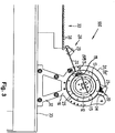
- the support frame 16 comprises two lateral covers 31, 31 ′, which are each connected to a frame 32.
- the two frames 32 rest on a pedestal 33.
- the side covers 31, 31 ' comprise additional cover parts.
- the additional cover parts 31'a and 31'b of the cover 31 ' are visible.
- the cover 31 also has corresponding cover parts, which are shown in FIG Figure 1 are covered.
- the drum 11 consists of a plurality of spaced apart flat rings 34 lined up on fastening strips 35 (cf. Fig. 6 ), which form a tube-like hollow body, on the inner wall 25 of which a round rod-shaped driver 15 extending over the entire length of the drum is attached. This gives the drum a sieve-like structure.
- the drum length can easily be varied by the number or the spacing of the flat rings 34 in a row.
- the closure element 13 is designed as a partial area of the drum shell 12 and closes the interior 40 in the closed position SP. In the open position OP, the closure element 13 exposes the opening 14.
- the change of the closure element 13 from the open position OP to the closed position SP and vice versa takes place in the illustrated Embodiment with rotation of the drum 11 due to gravity and without additional drive (cf. Figures 4 , 6 and 7 ).
- a separate drive can also be provided, for example to enable opening and closing in other rotational positions of the drum or at greater speed.
- the closure element 13 is designed in the form of an opening flap 21 which is rotatable about a pivot axis 19 and also extends over the entire length of the drum.
- the opening and closing of the opening flap 21 takes place in the illustrated embodiment on the basis of gravity, that is: no additional drive is required to operate the opening flap 21.
- the loading station 20 in its simplest form is formed by one or two laterally delimited strips 24 which hold a batch (bundle of bars 23, cf. Fig. 3 ) be able to record.
- the strips 24 are fastened to the covers 31, 31 ′ in such a way that they slide over the drum shell 12. If the opening 14 hits the loading station 20 during the rotation of the drum 11, the entire bundle of rods 23 automatically falls through this opening 14 into the drum 11 due to gravity.
- other loading devices can also be used.
- the rolling track 17 lying within the drum 11 has several comb-like gaps or notches 26 pointing in the direction of the ejection station 28, which - in the case of the one in an ejection position P1 (cf. Fig. 7 ) located closure element 13 - engage with corresponding notches 27 of the closure element 13 (opening flap 21) and thus form a guide device 18 for ejecting a separated rod 10 through the opening 14.
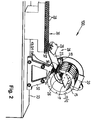
- the ejection station 28 comprises a chute 22, which with its one edge 36 almost engages into the opening 14 of the drum 11 and with its opposite bending edge 37 (cf. Fig. 2 ) is supported on the removal station 30, as well as a pivoting flap 29 located in the area of the bending edge 37.
- the slide 22 is arranged approximately plane-parallel to the roll-off track 17 or below the roll-off track and is slightly lowered relative to the roll-off track 17 so that the downhill rolling or sliding profiles of the guide device 18 fall directly onto the chute 22 and can be transported further.
- the removal station 30 is a belt conveyor or removal table which is an extension of the chute 22.
- the removal station 30 has a plurality of recesses 38 to be received by the profiles (rods 10).
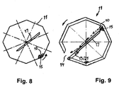
- FIGS. 8 and 9 show an alternative embodiment of a drum 11. Instead of a circular interior, this has a polygonal, in the illustrated embodiment: octagonal, contour. In this way, the alignment of the rods 10 on the base of the drum 11 can be promoted under certain operating conditions.
- a triangular driver contour is provided.
- round drums can also be equipped with triangular drivers or polygonal drums with round drivers.
- the design of the drum and driver contours depends on the respective application requirements.
- a bundle of rods 23 is loosely inserted and the unloaded drum 11 is set in rotation with the aid of a manually operated or remote-controlled electric drive.
- a V-trough or pre-separation can also be provided.
- the closure element 13 After a rotation of about 150 °, the closure element 13 automatically pivots as a result of gravity towards the interior of the drum 11 and releases the opening 14. First of all, a small opening gap is formed which, as the rotary movement continues (rotary phase b to rotary phase c), increases in size and finally opens the opening 14 completely.
- the drum is thus in the filling position P2 and the closure element 13 in the open position OP.
- the stock of bars in this filling position P2 in the through the opening 14 get into the drum 11. The bar material thus falls into the drum 11 and collects in its lower part.
- Rotation phase c also shows that the driver 15 is almost at its lowest position when the drum is in the filling position P2. Depending on the way in which the rods 10 fall into the drum 11, the driver 15 takes a rod 10 with it in the most favorable case. In the worst case, a rotation of 360 ° is required so that the driver 15 does not grasp the first rod 10 until the drum revolution following the filling.
- the driver 15 When the rotary movement continues from rotary phase d through rotary phase e in rotary phase f, the driver 15 first has its lowest position (detail "w" and Figure 5b ) taken, presses against the accumulated rods 10 and moves them in the direction of rotation F until the driver 15 assumes a position in which it is not able to hold all rods 10. Some rods 10 slide down over the driver 15, as shown in the detail "x" with the associated enlargement Figure 5c shows. At the same time, the closure element 13 has again moved from the closed position SP into the open position OP and is pivoted inward. A stop, not shown in more detail, limits the open position of the closure element 13.
- the closure element 13 having the notches 27 is pivoted maximally into the interior of the drum 11.
- the notches 26 of the closure element 13 and the notches 27 of the roll-off track 17 interlock, so that the closure element 13 roll-off track 17 jointly forms the already mentioned guide device 18 form.
- the last rod 10 held by the driver 15 up to this point can now also be moved from the driver 15 onto the guide device 18 and reaches the chute 22 via the opening 14.
- the closing element 13 is pressed down by its weight and by the bundle of rods into the closed position SP and closes the drum 11.
- a rod 10 is selected and conveyed out of the drum until the last rod 10 is also ejected from the rod layer 39 by the driver 10 onto the guide device 18.
Landscapes
- Engineering & Computer Science (AREA)
- Mechanical Engineering (AREA)
- Specific Conveyance Elements (AREA)
- Filling Or Emptying Of Bunkers, Hoppers, And Tanks (AREA)
Claims (13)
- Dispositif (100) pour séparer des profilés étirés en longueur, tels que des tiges (10), comprenant :- un tambour (11) supporté de manière rotative, avec un espace intérieur (40) et une enveloppe de tambour (12) cylindrique ou polygonale au niveau de laquelle est prévue au moins une ouverture (14),- ainsi qu'au moins un élément de fermeture (13) qui peut être déplacé d'une position de fermeture (SP) à une position d'ouverture (OP) et qui ferme et ouvre l'ouverture (14),- au moins un dispositif d'entraînement (15) accouplé à l'enveloppe de tambour (12) ou intégré dans l'enveloppe de tambour (12), pour sélectionner une tige individuelle (10),un cadre porteur (16) disposé à l'extérieur du tambour (11) étant prévu, lequel porte une voie de roulement (17) placée obliquement, se trouvant dans le tambour (11), et le tambour (11) pouvant tourner dans une position d'éjection (P1) dans laquelle une tige (10) sélectionnée par le dispositif d'entraînement (15) peut être acheminée à la voie de roulement (17), caractérisé en ce que l'élément de fermeture (13) se trouve dans la position d'ouverture (OP) et forme conjointement avec la voie de roulement (17) un système directeur (18) pour éjecter la tige (10) à travers l'ouverture (14).
- Dispositif (100) selon la revendication 1, caractérisé en ce que le tambour (11) peut tourner dans une position de remplissage (P2) dans laquelle une ou plusieurs tiges (10) peuvent être acheminées à travers l'ouverture (14) dans l'espace intérieur (40) lorsque l'élément de fermeture (13) se trouve dans la position d'ouverture (OP).
- Dispositif (100) selon l'une quelconque des revendications 1 et 2, caractérisé en ce qu'une bascule ou une glissière (22) ou un autre moyen de transport est monté(e) après le système directeur (18).
- Dispositif (100) selon l'une quelconque des revendications 1 à 3, caractérisé en ce que l'élément de fermeture (13) est réalisé sous forme de clapet d'ouverture pivotant (21) dont l'axe de pivotement (19) s'étend à la manière d'une ligne d'enveloppe le long de l'enveloppe de tambour (12).
- Dispositif (100) selon l'une quelconque des revendications 1 à 4, caractérisé en ce qu'un poste d'alimentation (20) pour recevoir et transférer des tiges individuelles (10) ou un faisceau de tiges (23) par le biais de l'ouverture (14) dans l'espace intérieur (40) du tambour (11) est disposé sur le tambour (11) ou au-dessus de celui-ci.
- Dispositif (100) selon la revendication 5, caractérisé en ce que le poste d'alimentation (20) comprend une trémie s'étendant le long du tambour (11), une glissière de remplissage ou au moins une baguette (24) limitée latéralement.
- Dispositif (100) selon l'une quelconque des revendications 1 à 6, caractérisé en ce que le dispositif d'entraînement (15) pour sélectionner une tige individuelle (10) est une barre profilée fixée à une paroi intérieure (25) du tambour (11), telle qu'une barre triangulaire ou carrée, de préférence une barre ronde.
- Dispositif (100) selon l'une quelconque des revendications 1 à 7, caractérisé en ce que le dispositif d'entraînement (15) pour sélectionner une tige individuelle (10) peut être interchangé ou ajusté de telle sorte que lors de la rotation du tambour (11) dans la position d'éjection (P1), seulement une tige individuelle (10) soit retenue par le dispositif d'entraînement (15) et que d'autres tiges (10) entraînées en même temps initialement par le dispositif d'entraînement (15) se détachent du dispositif d'entraînement (15) avant d'atteindre la position d'éjection (P1).
- Dispositif (100) selon l'une quelconque des revendications 1 à 7, caractérisé en ce que le dispositif d'entraînement (15) pour sélectionner les tiges (10) est réalisé dans une pièce de matériau conjointement avec le tambour (11).
- Dispositif (100) selon l'une quelconque des revendications 1 à 9, caractérisé en ce que le tambour (11) et/ou le clapet d'ouverture (21) et/ou la voie de roulement (17) sont réalisés au moins en partie en forme de peigne.
- Dispositif (100) selon la revendication 10, caractérisé en ce que la voie de roulement (17) et le clapet d'ouverture (21), dans la position d'éjection (P1) et/ou dans la position de remplissage (P2) du tambour (11), s'engagent l'un dans l'autre avec leurs entailles en forme de peigne (26 ; 27).
- Dispositif (100) selon l'une quelconque des revendications 1 à 11, caractérisé en ce que le tambour (11) peut être réalisé au moins en partie en forme de tamis ou en forme de grille ou peut être perforé.
- Dispositif (100) selon l'une quelconque des revendications 1 à 12, caractérisé en ce que le tambour, en plus de l'ouverture (14), de l'élément de fermeture (13) et du dispositif d'entraînement (15), comprend au moins une ouverture supplémentaire, un élément de fermeture supplémentaire et un dispositif d'entraînement supplémentaire qui sont disposés de telle sorte que dans le cas d'une rotation du tambour (11) après la sélection d'une première tige (10), au moins une tige supplémentaire (10) puisse être sélectionnée.
Priority Applications (1)
| Application Number | Priority Date | Filing Date | Title |
|---|---|---|---|
| PL19167117T PL3552993T3 (pl) | 2018-04-12 | 2019-04-03 | Urządzenie rozdzielające |
Applications Claiming Priority (1)
| Application Number | Priority Date | Filing Date | Title |
|---|---|---|---|
| DE102018108730.6A DE102018108730A1 (de) | 2018-04-12 | 2018-04-12 | Vereinzelungsmaschine |
Publications (2)
| Publication Number | Publication Date |
|---|---|
| EP3552993A1 EP3552993A1 (fr) | 2019-10-16 |
| EP3552993B1 true EP3552993B1 (fr) | 2020-12-16 |
Family
ID=66092088
Family Applications (1)
| Application Number | Title | Priority Date | Filing Date |
|---|---|---|---|
| EP19167117.1A Not-in-force EP3552993B1 (fr) | 2018-04-12 | 2019-04-03 | Machine de séparation |
Country Status (4)
| Country | Link |
|---|---|
| EP (1) | EP3552993B1 (fr) |
| DE (1) | DE102018108730A1 (fr) |
| ES (1) | ES2857960T3 (fr) |
| PL (1) | PL3552993T3 (fr) |
Families Citing this family (3)
| Publication number | Priority date | Publication date | Assignee | Title |
|---|---|---|---|---|
| CN112607446A (zh) * | 2020-11-24 | 2021-04-06 | 洛阳兰迪玻璃机器股份有限公司 | 一种支撑物自动排序机构、支撑物分离装置及其布放系统 |
| CN116692452A (zh) * | 2023-07-17 | 2023-09-05 | 马鞍山石冶机械制造有限公司 | 一种管件加工上料装置 |
| CN117184828A (zh) * | 2023-09-08 | 2023-12-08 | 千年舟新材科技集团股份有限公司 | 筒状物高效定向输送装置 |
Family Cites Families (8)
| Publication number | Priority date | Publication date | Assignee | Title |
|---|---|---|---|---|
| BE470115A (fr) * | ||||
| US3815730A (en) * | 1972-08-02 | 1974-06-11 | T Zwiep | Orienting apparatus and method |
| US5011024A (en) * | 1989-10-23 | 1991-04-30 | Bunney Leroy R | Rotary log sorter |
| JPH08198434A (ja) * | 1995-01-30 | 1996-08-06 | Yuyama Seisakusho:Kk | 薬剤の払出し方法およびその装置 |
| DE19637109C1 (de) * | 1996-09-12 | 1997-11-13 | Freudenberg Carl Fa | Fördervorrichtung |
| JP2004182456A (ja) * | 2002-12-06 | 2004-07-02 | Murata Mfg Co Ltd | チップ部品の整列供給装置 |
| DE102006018254A1 (de) * | 2006-04-20 | 2007-10-25 | Häfner, Jochen, Dipl.-Ing. | Trommelfördersilo |
| DE102008026883B4 (de) * | 2008-06-05 | 2018-09-27 | Johnson & Johnson Gmbh | Trommel für ein System, System und Verfahren zum Ausrichten, Sortieren und/oder Ordnen von chaotisch zueinander liegenden Gegenständen |
-
2018
- 2018-04-12 DE DE102018108730.6A patent/DE102018108730A1/de not_active Withdrawn
-
2019
- 2019-04-03 EP EP19167117.1A patent/EP3552993B1/fr not_active Not-in-force
- 2019-04-03 ES ES19167117T patent/ES2857960T3/es active Active
- 2019-04-03 PL PL19167117T patent/PL3552993T3/pl unknown
Non-Patent Citations (1)
| Title |
|---|
| None * |
Also Published As
| Publication number | Publication date |
|---|---|
| EP3552993A1 (fr) | 2019-10-16 |
| DE102018108730A1 (de) | 2019-10-17 |
| PL3552993T3 (pl) | 2021-07-19 |
| ES2857960T3 (es) | 2021-09-29 |
Similar Documents
| Publication | Publication Date | Title |
|---|---|---|
| DE69300354T2 (de) | Einrichtung zum automatischen Positionieren und Ausrichten von Behältern. | |
| DE2747866C2 (de) | Vorrichtung zum Ausstreuen von Saatgut | |
| EP3552993B1 (fr) | Machine de séparation | |
| DE102013215233A1 (de) | Beladeteller einer Beschickungsanlage für eine Verpackungsmaschine für Süßwaren | |
| DE2031286C2 (de) | Vorrichtung zum Herstellen eines Leuchtschirms | |
| EP2130445B1 (fr) | Dispositif et procédé de vidage successif de récipients remplis de produits en forme de tiges | |
| EP2762034B1 (fr) | Tampon pour brosses | |
| DE6610240U (de) | Vorrichtung zum entladen von zigarettenschragen od. dgl. behaeltern. | |
| DE2437795A1 (de) | Vorrichtung zum entladen von dosen oder dgl. rohrfoermigen behaeltern | |
| EP1671903B1 (fr) | Dispositif pour le transport individuel d'objets légers de petite taille, en particulier de comprimés | |
| AT410204B (de) | Einrichtung zum vereinzeln und ausschleusen von in einer reihe auf einer rollenbahn abgelegten stückgütern | |
| DE4118883A1 (de) | Vorrichtung zum abreibenden und entstaubenden handling von losen schuettguetern, insbesondere zum entgraten und entstauben von aus einer tablettenpresse zugefuehrten tabletten oder pillen nach dem pressvorgang | |
| DE2629634A1 (de) | Vorrichtung zum trennen und ordnen von muenzen u.dgl. | |
| DE2458394A1 (de) | Vorrichtung zum transportieren einer vorbestimmten anzahl gegenstaende sowie verwendung einer solchen vorrichtung | |
| DE202018101996U1 (de) | Vereinzelungsmaschine | |
| DE3321173C2 (fr) | ||
| DE60002817T2 (de) | Vorrichtung zum Zuführen von Etiketten zu einer Etikettiermaschine | |
| DE4425522C2 (de) | Band-Zellenausleser zum Separieren fließfähiger Schüttgüter | |
| DE29803676U1 (de) | Metallfördereinrichtung | |
| DE2729885B2 (de) | Vorrichtung zum Vereinzeln und Ausrichten gleichartiger, einendig geschlossener, hohler Werkstücke, wie Kartuschhülsen o.dgl | |
| DE2520685C3 (de) | Vorrichtung zum Zählen und dosierten Abfüllen von Tabletten, Dragees, Gelatinekapseln u.dgl. Körpern | |
| DE19704421B4 (de) | Vorrichtung zur Bildung von Bunden aus Walzdrahtschlingen | |
| DE2659287A1 (de) | Einrichtung zur ausrichtung von gegenstaenden | |
| DE2550987A1 (de) | Vorrichtung zum zaehlen und dosierten abfuellen von tabletten, dragees, gelatinekapseln u.dgl. koerpern | |
| DE2249308C3 (de) | Verfahren und Vorrichtung zum Ordnen von Aerosol-Kappen |
Legal Events
| Date | Code | Title | Description |
|---|---|---|---|
| PUAI | Public reference made under article 153(3) epc to a published international application that has entered the european phase |
Free format text: ORIGINAL CODE: 0009012 |
|
| STAA | Information on the status of an ep patent application or granted ep patent |
Free format text: STATUS: THE APPLICATION HAS BEEN PUBLISHED |
|
| AK | Designated contracting states |
Kind code of ref document: A1 Designated state(s): AL AT BE BG CH CY CZ DE DK EE ES FI FR GB GR HR HU IE IS IT LI LT LU LV MC MK MT NL NO PL PT RO RS SE SI SK SM TR |
|
| AX | Request for extension of the european patent |
Extension state: BA ME |
|
| STAA | Information on the status of an ep patent application or granted ep patent |
Free format text: STATUS: REQUEST FOR EXAMINATION WAS MADE |
|
| 17P | Request for examination filed |
Effective date: 20200211 |
|
| RBV | Designated contracting states (corrected) |
Designated state(s): AL AT BE BG CH CY CZ DE DK EE ES FI FR GB GR HR HU IE IS IT LI LT LU LV MC MK MT NL NO PL PT RO RS SE SI SK SM TR |
|
| GRAP | Despatch of communication of intention to grant a patent |
Free format text: ORIGINAL CODE: EPIDOSNIGR1 |
|
| STAA | Information on the status of an ep patent application or granted ep patent |
Free format text: STATUS: GRANT OF PATENT IS INTENDED |
|
| RIC1 | Information provided on ipc code assigned before grant |
Ipc: B65G 47/14 20060101AFI20200619BHEP |
|
| INTG | Intention to grant announced |
Effective date: 20200721 |
|
| GRAS | Grant fee paid |
Free format text: ORIGINAL CODE: EPIDOSNIGR3 |
|
| GRAA | (expected) grant |
Free format text: ORIGINAL CODE: 0009210 |
|
| STAA | Information on the status of an ep patent application or granted ep patent |
Free format text: STATUS: THE PATENT HAS BEEN GRANTED |
|
| AK | Designated contracting states |
Kind code of ref document: B1 Designated state(s): AL AT BE BG CH CY CZ DE DK EE ES FI FR GB GR HR HU IE IS IT LI LT LU LV MC MK MT NL NO PL PT RO RS SE SI SK SM TR |
|
| REG | Reference to a national code |
Ref country code: GB Ref legal event code: FG4D Free format text: NOT ENGLISH |
|
| REG | Reference to a national code |
Ref country code: IE Ref legal event code: FG4D Free format text: LANGUAGE OF EP DOCUMENT: GERMAN |
|
| REG | Reference to a national code |
Ref country code: DE Ref legal event code: R096 Ref document number: 502019000526 Country of ref document: DE |
|
| REG | Reference to a national code |
Ref country code: AT Ref legal event code: REF Ref document number: 1345400 Country of ref document: AT Kind code of ref document: T Effective date: 20210115 |
|
| REG | Reference to a national code |
Ref country code: CH Ref legal event code: NV Representative=s name: R.A. EGLI AND CO, PATENTANWAELTE, CH |
|
| REG | Reference to a national code |
Ref country code: NL Ref legal event code: FP |
|
| PG25 | Lapsed in a contracting state [announced via postgrant information from national office to epo] |
Ref country code: NO Free format text: LAPSE BECAUSE OF FAILURE TO SUBMIT A TRANSLATION OF THE DESCRIPTION OR TO PAY THE FEE WITHIN THE PRESCRIBED TIME-LIMIT Effective date: 20210316 Ref country code: GR Free format text: LAPSE BECAUSE OF FAILURE TO SUBMIT A TRANSLATION OF THE DESCRIPTION OR TO PAY THE FEE WITHIN THE PRESCRIBED TIME-LIMIT Effective date: 20210317 Ref country code: FI Free format text: LAPSE BECAUSE OF FAILURE TO SUBMIT A TRANSLATION OF THE DESCRIPTION OR TO PAY THE FEE WITHIN THE PRESCRIBED TIME-LIMIT Effective date: 20201216 Ref country code: RS Free format text: LAPSE BECAUSE OF FAILURE TO SUBMIT A TRANSLATION OF THE DESCRIPTION OR TO PAY THE FEE WITHIN THE PRESCRIBED TIME-LIMIT Effective date: 20201216 |
|
| PGFP | Annual fee paid to national office [announced via postgrant information from national office to epo] |
Ref country code: FR Payment date: 20210225 Year of fee payment: 3 Ref country code: CZ Payment date: 20210317 Year of fee payment: 3 |
|
| PG25 | Lapsed in a contracting state [announced via postgrant information from national office to epo] |
Ref country code: LV Free format text: LAPSE BECAUSE OF FAILURE TO SUBMIT A TRANSLATION OF THE DESCRIPTION OR TO PAY THE FEE WITHIN THE PRESCRIBED TIME-LIMIT Effective date: 20201216 Ref country code: SE Free format text: LAPSE BECAUSE OF FAILURE TO SUBMIT A TRANSLATION OF THE DESCRIPTION OR TO PAY THE FEE WITHIN THE PRESCRIBED TIME-LIMIT Effective date: 20201216 Ref country code: BG Free format text: LAPSE BECAUSE OF FAILURE TO SUBMIT A TRANSLATION OF THE DESCRIPTION OR TO PAY THE FEE WITHIN THE PRESCRIBED TIME-LIMIT Effective date: 20210316 |
|
| PGFP | Annual fee paid to national office [announced via postgrant information from national office to epo] |
Ref country code: TR Payment date: 20210326 Year of fee payment: 3 |
|
| PG25 | Lapsed in a contracting state [announced via postgrant information from national office to epo] |
Ref country code: HR Free format text: LAPSE BECAUSE OF FAILURE TO SUBMIT A TRANSLATION OF THE DESCRIPTION OR TO PAY THE FEE WITHIN THE PRESCRIBED TIME-LIMIT Effective date: 20201216 |
|
| REG | Reference to a national code |
Ref country code: LT Ref legal event code: MG9D |
|
| PG25 | Lapsed in a contracting state [announced via postgrant information from national office to epo] |
Ref country code: EE Free format text: LAPSE BECAUSE OF FAILURE TO SUBMIT A TRANSLATION OF THE DESCRIPTION OR TO PAY THE FEE WITHIN THE PRESCRIBED TIME-LIMIT Effective date: 20201216 Ref country code: SM Free format text: LAPSE BECAUSE OF FAILURE TO SUBMIT A TRANSLATION OF THE DESCRIPTION OR TO PAY THE FEE WITHIN THE PRESCRIBED TIME-LIMIT Effective date: 20201216 Ref country code: SK Free format text: LAPSE BECAUSE OF FAILURE TO SUBMIT A TRANSLATION OF THE DESCRIPTION OR TO PAY THE FEE WITHIN THE PRESCRIBED TIME-LIMIT Effective date: 20201216 Ref country code: PT Free format text: LAPSE BECAUSE OF FAILURE TO SUBMIT A TRANSLATION OF THE DESCRIPTION OR TO PAY THE FEE WITHIN THE PRESCRIBED TIME-LIMIT Effective date: 20210416 Ref country code: RO Free format text: LAPSE BECAUSE OF FAILURE TO SUBMIT A TRANSLATION OF THE DESCRIPTION OR TO PAY THE FEE WITHIN THE PRESCRIBED TIME-LIMIT Effective date: 20201216 Ref country code: LT Free format text: LAPSE BECAUSE OF FAILURE TO SUBMIT A TRANSLATION OF THE DESCRIPTION OR TO PAY THE FEE WITHIN THE PRESCRIBED TIME-LIMIT Effective date: 20201216 |
|
| PGFP | Annual fee paid to national office [announced via postgrant information from national office to epo] |
Ref country code: PL Payment date: 20210302 Year of fee payment: 3 Ref country code: ES Payment date: 20210507 Year of fee payment: 3 |
|
| REG | Reference to a national code |
Ref country code: DE Ref legal event code: R097 Ref document number: 502019000526 Country of ref document: DE |
|
| REG | Reference to a national code |
Ref country code: ES Ref legal event code: FG2A Ref document number: 2857960 Country of ref document: ES Kind code of ref document: T3 Effective date: 20210929 |
|
| PG25 | Lapsed in a contracting state [announced via postgrant information from national office to epo] |
Ref country code: IS Free format text: LAPSE BECAUSE OF FAILURE TO SUBMIT A TRANSLATION OF THE DESCRIPTION OR TO PAY THE FEE WITHIN THE PRESCRIBED TIME-LIMIT Effective date: 20210416 |
|
| PLBE | No opposition filed within time limit |
Free format text: ORIGINAL CODE: 0009261 |
|
| STAA | Information on the status of an ep patent application or granted ep patent |
Free format text: STATUS: NO OPPOSITION FILED WITHIN TIME LIMIT |
|
| PG25 | Lapsed in a contracting state [announced via postgrant information from national office to epo] |
Ref country code: AL Free format text: LAPSE BECAUSE OF FAILURE TO SUBMIT A TRANSLATION OF THE DESCRIPTION OR TO PAY THE FEE WITHIN THE PRESCRIBED TIME-LIMIT Effective date: 20201216 |
|
| 26N | No opposition filed |
Effective date: 20210917 |
|
| PG25 | Lapsed in a contracting state [announced via postgrant information from national office to epo] |
Ref country code: MC Free format text: LAPSE BECAUSE OF FAILURE TO SUBMIT A TRANSLATION OF THE DESCRIPTION OR TO PAY THE FEE WITHIN THE PRESCRIBED TIME-LIMIT Effective date: 20201216 Ref country code: DK Free format text: LAPSE BECAUSE OF FAILURE TO SUBMIT A TRANSLATION OF THE DESCRIPTION OR TO PAY THE FEE WITHIN THE PRESCRIBED TIME-LIMIT Effective date: 20201216 |
|
| PG25 | Lapsed in a contracting state [announced via postgrant information from national office to epo] |
Ref country code: LU Free format text: LAPSE BECAUSE OF NON-PAYMENT OF DUE FEES Effective date: 20210403 |
|
| REG | Reference to a national code |
Ref country code: BE Ref legal event code: MM Effective date: 20210430 |
|
| PG25 | Lapsed in a contracting state [announced via postgrant information from national office to epo] |
Ref country code: SI Free format text: LAPSE BECAUSE OF FAILURE TO SUBMIT A TRANSLATION OF THE DESCRIPTION OR TO PAY THE FEE WITHIN THE PRESCRIBED TIME-LIMIT Effective date: 20201216 |
|
| PG25 | Lapsed in a contracting state [announced via postgrant information from national office to epo] |
Ref country code: IE Free format text: LAPSE BECAUSE OF NON-PAYMENT OF DUE FEES Effective date: 20210403 |
|
| PG25 | Lapsed in a contracting state [announced via postgrant information from national office to epo] |
Ref country code: IS Free format text: LAPSE BECAUSE OF FAILURE TO SUBMIT A TRANSLATION OF THE DESCRIPTION OR TO PAY THE FEE WITHIN THE PRESCRIBED TIME-LIMIT Effective date: 20210416 |
|
| PG25 | Lapsed in a contracting state [announced via postgrant information from national office to epo] |
Ref country code: BE Free format text: LAPSE BECAUSE OF NON-PAYMENT OF DUE FEES Effective date: 20210430 |
|
| PGFP | Annual fee paid to national office [announced via postgrant information from national office to epo] |
Ref country code: IT Payment date: 20220430 Year of fee payment: 4 |
|
| PG25 | Lapsed in a contracting state [announced via postgrant information from national office to epo] |
Ref country code: CZ Free format text: LAPSE BECAUSE OF NON-PAYMENT OF DUE FEES Effective date: 20220403 |
|
| REG | Reference to a national code |
Ref country code: CH Ref legal event code: PL |
|
| REG | Reference to a national code |
Ref country code: NL Ref legal event code: MM Effective date: 20220501 |
|
| PG25 | Lapsed in a contracting state [announced via postgrant information from national office to epo] |
Ref country code: NL Free format text: LAPSE BECAUSE OF NON-PAYMENT OF DUE FEES Effective date: 20220501 Ref country code: LI Free format text: LAPSE BECAUSE OF NON-PAYMENT OF DUE FEES Effective date: 20220430 Ref country code: FR Free format text: LAPSE BECAUSE OF NON-PAYMENT OF DUE FEES Effective date: 20220430 Ref country code: CH Free format text: LAPSE BECAUSE OF NON-PAYMENT OF DUE FEES Effective date: 20220430 |
|
| REG | Reference to a national code |
Ref country code: ES Ref legal event code: FD2A Effective date: 20230526 |
|
| PG25 | Lapsed in a contracting state [announced via postgrant information from national office to epo] |
Ref country code: CY Free format text: LAPSE BECAUSE OF FAILURE TO SUBMIT A TRANSLATION OF THE DESCRIPTION OR TO PAY THE FEE WITHIN THE PRESCRIBED TIME-LIMIT Effective date: 20201216 |
|
| PG25 | Lapsed in a contracting state [announced via postgrant information from national office to epo] |
Ref country code: HU Free format text: LAPSE BECAUSE OF FAILURE TO SUBMIT A TRANSLATION OF THE DESCRIPTION OR TO PAY THE FEE WITHIN THE PRESCRIBED TIME-LIMIT; INVALID AB INITIO Effective date: 20190403 Ref country code: ES Free format text: LAPSE BECAUSE OF NON-PAYMENT OF DUE FEES Effective date: 20220404 |
|
| PGFP | Annual fee paid to national office [announced via postgrant information from national office to epo] |
Ref country code: DE Payment date: 20230424 Year of fee payment: 5 |
|
| GBPC | Gb: european patent ceased through non-payment of renewal fee |
Effective date: 20230403 |
|
| PG25 | Lapsed in a contracting state [announced via postgrant information from national office to epo] |
Ref country code: GB Free format text: LAPSE BECAUSE OF NON-PAYMENT OF DUE FEES Effective date: 20230403 |
|
| PG25 | Lapsed in a contracting state [announced via postgrant information from national office to epo] |
Ref country code: GB Free format text: LAPSE BECAUSE OF NON-PAYMENT OF DUE FEES Effective date: 20230403 |
|
| PG25 | Lapsed in a contracting state [announced via postgrant information from national office to epo] |
Ref country code: MK Free format text: LAPSE BECAUSE OF FAILURE TO SUBMIT A TRANSLATION OF THE DESCRIPTION OR TO PAY THE FEE WITHIN THE PRESCRIBED TIME-LIMIT Effective date: 20201216 Ref country code: IT Free format text: LAPSE BECAUSE OF NON-PAYMENT OF DUE FEES Effective date: 20230403 |
|
| PG25 | Lapsed in a contracting state [announced via postgrant information from national office to epo] |
Ref country code: PL Free format text: LAPSE BECAUSE OF NON-PAYMENT OF DUE FEES Effective date: 20220403 |
|
| PG25 | Lapsed in a contracting state [announced via postgrant information from national office to epo] |
Ref country code: TR Free format text: LAPSE BECAUSE OF NON-PAYMENT OF DUE FEES Effective date: 20220403 Ref country code: MT Free format text: LAPSE BECAUSE OF FAILURE TO SUBMIT A TRANSLATION OF THE DESCRIPTION OR TO PAY THE FEE WITHIN THE PRESCRIBED TIME-LIMIT Effective date: 20201216 |
|
| REG | Reference to a national code |
Ref country code: DE Ref legal event code: R119 Ref document number: 502019000526 Country of ref document: DE |
|
| PG25 | Lapsed in a contracting state [announced via postgrant information from national office to epo] |
Ref country code: DE Free format text: LAPSE BECAUSE OF NON-PAYMENT OF DUE FEES Effective date: 20241105 |
|
| PG25 | Lapsed in a contracting state [announced via postgrant information from national office to epo] |
Ref country code: DE Free format text: LAPSE BECAUSE OF NON-PAYMENT OF DUE FEES Effective date: 20241105 |
|
| REG | Reference to a national code |
Ref country code: AT Ref legal event code: MM01 Ref document number: 1345400 Country of ref document: AT Kind code of ref document: T Effective date: 20240403 |
|
| PG25 | Lapsed in a contracting state [announced via postgrant information from national office to epo] |
Ref country code: AT Free format text: LAPSE BECAUSE OF NON-PAYMENT OF DUE FEES Effective date: 20240403 |