EP3551422B1 - Verfahren zur herstellung einer schuhsohle - Google Patents
Verfahren zur herstellung einer schuhsohle Download PDFInfo
- Publication number
- EP3551422B1 EP3551422B1 EP16822379.0A EP16822379A EP3551422B1 EP 3551422 B1 EP3551422 B1 EP 3551422B1 EP 16822379 A EP16822379 A EP 16822379A EP 3551422 B1 EP3551422 B1 EP 3551422B1
- Authority
- EP
- European Patent Office
- Prior art keywords
- plastic
- sole
- hollow body
- blow
- insert
- Prior art date
- Legal status (The legal status is an assumption and is not a legal conclusion. Google has not performed a legal analysis and makes no representation as to the accuracy of the status listed.)
- Active
Links
Images

Classifications
-
- B—PERFORMING OPERATIONS; TRANSPORTING
- B29—WORKING OF PLASTICS; WORKING OF SUBSTANCES IN A PLASTIC STATE IN GENERAL
- B29C—SHAPING OR JOINING OF PLASTICS; SHAPING OF MATERIAL IN A PLASTIC STATE, NOT OTHERWISE PROVIDED FOR; AFTER-TREATMENT OF THE SHAPED PRODUCTS, e.g. REPAIRING
- B29C49/00—Blow-moulding, i.e. blowing a preform or parison to a desired shape within a mould; Apparatus therefor
- B29C49/42—Component parts, details or accessories; Auxiliary operations
- B29C49/48—Moulds
- B29C49/4802—Moulds with means for locally compressing part(s) of the parison in the main blowing cavity
-
- A—HUMAN NECESSITIES
- A43—FOOTWEAR
- A43B—CHARACTERISTIC FEATURES OF FOOTWEAR; PARTS OF FOOTWEAR
- A43B13/00—Soles; Sole-and-heel integral units
- A43B13/02—Soles; Sole-and-heel integral units characterised by the material
- A43B13/04—Plastics, rubber or vulcanised fibre
-
- A—HUMAN NECESSITIES
- A43—FOOTWEAR
- A43B—CHARACTERISTIC FEATURES OF FOOTWEAR; PARTS OF FOOTWEAR
- A43B13/00—Soles; Sole-and-heel integral units
- A43B13/14—Soles; Sole-and-heel integral units characterised by the constructive form
-
- A—HUMAN NECESSITIES
- A43—FOOTWEAR
- A43B—CHARACTERISTIC FEATURES OF FOOTWEAR; PARTS OF FOOTWEAR
- A43B13/00—Soles; Sole-and-heel integral units
- A43B13/14—Soles; Sole-and-heel integral units characterised by the constructive form
- A43B13/18—Resilient soles
- A43B13/187—Resiliency achieved by the features of the material, e.g. foam, non liquid materials
-
- B—PERFORMING OPERATIONS; TRANSPORTING
- B29—WORKING OF PLASTICS; WORKING OF SUBSTANCES IN A PLASTIC STATE IN GENERAL
- B29C—SHAPING OR JOINING OF PLASTICS; SHAPING OF MATERIAL IN A PLASTIC STATE, NOT OTHERWISE PROVIDED FOR; AFTER-TREATMENT OF THE SHAPED PRODUCTS, e.g. REPAIRING
- B29C49/00—Blow-moulding, i.e. blowing a preform or parison to a desired shape within a mould; Apparatus therefor
- B29C49/02—Combined blow-moulding and manufacture of the preform or the parison
- B29C49/04—Extrusion blow-moulding
-
- B—PERFORMING OPERATIONS; TRANSPORTING
- B29—WORKING OF PLASTICS; WORKING OF SUBSTANCES IN A PLASTIC STATE IN GENERAL
- B29C—SHAPING OR JOINING OF PLASTICS; SHAPING OF MATERIAL IN A PLASTIC STATE, NOT OTHERWISE PROVIDED FOR; AFTER-TREATMENT OF THE SHAPED PRODUCTS, e.g. REPAIRING
- B29C49/00—Blow-moulding, i.e. blowing a preform or parison to a desired shape within a mould; Apparatus therefor
- B29C49/02—Combined blow-moulding and manufacture of the preform or the parison
- B29C49/06—Injection blow-moulding
-
- B—PERFORMING OPERATIONS; TRANSPORTING
- B29—WORKING OF PLASTICS; WORKING OF SUBSTANCES IN A PLASTIC STATE IN GENERAL
- B29C—SHAPING OR JOINING OF PLASTICS; SHAPING OF MATERIAL IN A PLASTIC STATE, NOT OTHERWISE PROVIDED FOR; AFTER-TREATMENT OF THE SHAPED PRODUCTS, e.g. REPAIRING
- B29C49/00—Blow-moulding, i.e. blowing a preform or parison to a desired shape within a mould; Apparatus therefor
- B29C49/42—Component parts, details or accessories; Auxiliary operations
- B29C49/48—Moulds
-
- B—PERFORMING OPERATIONS; TRANSPORTING
- B29—WORKING OF PLASTICS; WORKING OF SUBSTANCES IN A PLASTIC STATE IN GENERAL
- B29C—SHAPING OR JOINING OF PLASTICS; SHAPING OF MATERIAL IN A PLASTIC STATE, NOT OTHERWISE PROVIDED FOR; AFTER-TREATMENT OF THE SHAPED PRODUCTS, e.g. REPAIRING
- B29C49/00—Blow-moulding, i.e. blowing a preform or parison to a desired shape within a mould; Apparatus therefor
- B29C49/02—Combined blow-moulding and manufacture of the preform or the parison
- B29C2049/023—Combined blow-moulding and manufacture of the preform or the parison using inherent heat of the preform, i.e. 1 step blow moulding
-
- B—PERFORMING OPERATIONS; TRANSPORTING
- B29—WORKING OF PLASTICS; WORKING OF SUBSTANCES IN A PLASTIC STATE IN GENERAL
- B29C—SHAPING OR JOINING OF PLASTICS; SHAPING OF MATERIAL IN A PLASTIC STATE, NOT OTHERWISE PROVIDED FOR; AFTER-TREATMENT OF THE SHAPED PRODUCTS, e.g. REPAIRING
- B29C49/00—Blow-moulding, i.e. blowing a preform or parison to a desired shape within a mould; Apparatus therefor
- B29C49/42—Component parts, details or accessories; Auxiliary operations
- B29C49/48—Moulds
- B29C49/4802—Moulds with means for locally compressing part(s) of the parison in the main blowing cavity
- B29C2049/4807—Moulds with means for locally compressing part(s) of the parison in the main blowing cavity by movable mould parts in the mould halves
-
- B—PERFORMING OPERATIONS; TRANSPORTING
- B29—WORKING OF PLASTICS; WORKING OF SUBSTANCES IN A PLASTIC STATE IN GENERAL
- B29C—SHAPING OR JOINING OF PLASTICS; SHAPING OF MATERIAL IN A PLASTIC STATE, NOT OTHERWISE PROVIDED FOR; AFTER-TREATMENT OF THE SHAPED PRODUCTS, e.g. REPAIRING
- B29C2949/00—Indexing scheme relating to blow-moulding
- B29C2949/07—Preforms or parisons characterised by their configuration
- B29C2949/0715—Preforms or parisons characterised by their configuration the preform having one end closed
-
- B—PERFORMING OPERATIONS; TRANSPORTING
- B29—WORKING OF PLASTICS; WORKING OF SUBSTANCES IN A PLASTIC STATE IN GENERAL
- B29C—SHAPING OR JOINING OF PLASTICS; SHAPING OF MATERIAL IN A PLASTIC STATE, NOT OTHERWISE PROVIDED FOR; AFTER-TREATMENT OF THE SHAPED PRODUCTS, e.g. REPAIRING
- B29C49/00—Blow-moulding, i.e. blowing a preform or parison to a desired shape within a mould; Apparatus therefor
- B29C49/42—Component parts, details or accessories; Auxiliary operations
- B29C49/48—Moulds
- B29C49/4802—Moulds with means for locally compressing part(s) of the parison in the main blowing cavity
- B29C49/4817—Moulds with means for locally compressing part(s) of the parison in the main blowing cavity with means for closing off parison ends
-
- B—PERFORMING OPERATIONS; TRANSPORTING
- B29—WORKING OF PLASTICS; WORKING OF SUBSTANCES IN A PLASTIC STATE IN GENERAL
- B29K—INDEXING SCHEME ASSOCIATED WITH SUBCLASSES B29B, B29C OR B29D, RELATING TO MOULDING MATERIALS OR TO MATERIALS FOR MOULDS, REINFORCEMENTS, FILLERS OR PREFORMED PARTS, e.g. INSERTS
- B29K2023/00—Use of polyalkenes or derivatives thereof as moulding material
- B29K2023/04—Polymers of ethylene
- B29K2023/06—PE, i.e. polyethylene
-
- B—PERFORMING OPERATIONS; TRANSPORTING
- B29—WORKING OF PLASTICS; WORKING OF SUBSTANCES IN A PLASTIC STATE IN GENERAL
- B29K—INDEXING SCHEME ASSOCIATED WITH SUBCLASSES B29B, B29C OR B29D, RELATING TO MOULDING MATERIALS OR TO MATERIALS FOR MOULDS, REINFORCEMENTS, FILLERS OR PREFORMED PARTS, e.g. INSERTS
- B29K2023/00—Use of polyalkenes or derivatives thereof as moulding material
- B29K2023/10—Polymers of propylene
- B29K2023/12—PP, i.e. polypropylene
-
- B—PERFORMING OPERATIONS; TRANSPORTING
- B29—WORKING OF PLASTICS; WORKING OF SUBSTANCES IN A PLASTIC STATE IN GENERAL
- B29K—INDEXING SCHEME ASSOCIATED WITH SUBCLASSES B29B, B29C OR B29D, RELATING TO MOULDING MATERIALS OR TO MATERIALS FOR MOULDS, REINFORCEMENTS, FILLERS OR PREFORMED PARTS, e.g. INSERTS
- B29K2027/00—Use of polyvinylhalogenides or derivatives thereof as moulding material
- B29K2027/06—PVC, i.e. polyvinylchloride
-
- B—PERFORMING OPERATIONS; TRANSPORTING
- B29—WORKING OF PLASTICS; WORKING OF SUBSTANCES IN A PLASTIC STATE IN GENERAL
- B29K—INDEXING SCHEME ASSOCIATED WITH SUBCLASSES B29B, B29C OR B29D, RELATING TO MOULDING MATERIALS OR TO MATERIALS FOR MOULDS, REINFORCEMENTS, FILLERS OR PREFORMED PARTS, e.g. INSERTS
- B29K2033/00—Use of polymers of unsaturated acids or derivatives thereof as moulding material
- B29K2033/04—Polymers of esters
- B29K2033/12—Polymers of methacrylic acid esters, e.g. PMMA, i.e. polymethylmethacrylate
-
- B—PERFORMING OPERATIONS; TRANSPORTING
- B29—WORKING OF PLASTICS; WORKING OF SUBSTANCES IN A PLASTIC STATE IN GENERAL
- B29K—INDEXING SCHEME ASSOCIATED WITH SUBCLASSES B29B, B29C OR B29D, RELATING TO MOULDING MATERIALS OR TO MATERIALS FOR MOULDS, REINFORCEMENTS, FILLERS OR PREFORMED PARTS, e.g. INSERTS
- B29K2059/00—Use of polyacetals, e.g. POM, i.e. polyoxymethylene or derivatives thereof, as moulding material
-
- B—PERFORMING OPERATIONS; TRANSPORTING
- B29—WORKING OF PLASTICS; WORKING OF SUBSTANCES IN A PLASTIC STATE IN GENERAL
- B29K—INDEXING SCHEME ASSOCIATED WITH SUBCLASSES B29B, B29C OR B29D, RELATING TO MOULDING MATERIALS OR TO MATERIALS FOR MOULDS, REINFORCEMENTS, FILLERS OR PREFORMED PARTS, e.g. INSERTS
- B29K2069/00—Use of PC, i.e. polycarbonates or derivatives thereof, as moulding material
-
- B—PERFORMING OPERATIONS; TRANSPORTING
- B29—WORKING OF PLASTICS; WORKING OF SUBSTANCES IN A PLASTIC STATE IN GENERAL
- B29K—INDEXING SCHEME ASSOCIATED WITH SUBCLASSES B29B, B29C OR B29D, RELATING TO MOULDING MATERIALS OR TO MATERIALS FOR MOULDS, REINFORCEMENTS, FILLERS OR PREFORMED PARTS, e.g. INSERTS
- B29K2075/00—Use of PU, i.e. polyureas or polyurethanes or derivatives thereof, as moulding material
-
- B—PERFORMING OPERATIONS; TRANSPORTING
- B29—WORKING OF PLASTICS; WORKING OF SUBSTANCES IN A PLASTIC STATE IN GENERAL
- B29K—INDEXING SCHEME ASSOCIATED WITH SUBCLASSES B29B, B29C OR B29D, RELATING TO MOULDING MATERIALS OR TO MATERIALS FOR MOULDS, REINFORCEMENTS, FILLERS OR PREFORMED PARTS, e.g. INSERTS
- B29K2077/00—Use of PA, i.e. polyamides, e.g. polyesteramides or derivatives thereof, as moulding material
-
- B—PERFORMING OPERATIONS; TRANSPORTING
- B29—WORKING OF PLASTICS; WORKING OF SUBSTANCES IN A PLASTIC STATE IN GENERAL
- B29K—INDEXING SCHEME ASSOCIATED WITH SUBCLASSES B29B, B29C OR B29D, RELATING TO MOULDING MATERIALS OR TO MATERIALS FOR MOULDS, REINFORCEMENTS, FILLERS OR PREFORMED PARTS, e.g. INSERTS
- B29K2995/00—Properties of moulding materials, reinforcements, fillers, preformed parts or moulds
- B29K2995/0037—Other properties
- B29K2995/0091—Damping, energy absorption
-
- B—PERFORMING OPERATIONS; TRANSPORTING
- B29—WORKING OF PLASTICS; WORKING OF SUBSTANCES IN A PLASTIC STATE IN GENERAL
- B29L—INDEXING SCHEME ASSOCIATED WITH SUBCLASS B29C, RELATING TO PARTICULAR ARTICLES
- B29L2031/00—Other particular articles
- B29L2031/48—Wearing apparel
- B29L2031/50—Footwear, e.g. shoes or parts thereof
- B29L2031/504—Soles
Definitions
- the invention relates to a method for producing a shoe sole, in particular one for a sports shoe.
- shoe soles especially for sports shoes
- the aim is not only to provide an economical process for production, but also to have the opportunity to influence the spring and damping behavior of the shoe sole and thus the shoe as well as possible.
- the material used also plays an important role here.
- the invention is therefore based on the object of providing a method with which a shoe sole can be manufactured inexpensively and its spring and damping behavior can be adjusted in a desired manner.
- the shoe sole should thus be able to be produced in an economical manner and with easily adjustable spring and damping properties.
- plastic body In particular, spheres, ellipsoids or cylinders are used as the plastic body.
- the dimensions of the individual plastic bodies in the three spatial directions are preferably between 1 mm and 13 mm, particularly preferably between 3 mm and 6 mm.
- the plastic bodies consist in particular of foamed plastic material.
- the hollow sole body is preferably made of thermoplastic polyurethane (TPU), thermoplastic elastomer (TPE), polyamide (PA) and / or rubber material.
- TPU thermoplastic polyurethane
- TPE thermoplastic elastomer
- PA polyamide
- step d) above the first opening is closed, in particular welded.
- step d) above air is sucked out of the hollow sole body. This is preferably done via a second opening that is spaced apart from the first opening.
- the plastic bodies are preferably placed in the hollow sole body without being connected to one another. Accordingly, the individual balls or ellipsoids are not connected to one another by any measures, but they are loosely placed in the hollow sole body.
- the plastic bodies are preferably placed in a full pack and preferably under pressure in the hollow sole body.
- the support structure is preferably produced in that one indentation with a closed end region is produced in one wall by means of a first deformation tool and the other indentation with an open end region is produced in the other wall by means of a second deformation tool, the closed end region being the one indentation is formed to enter the open end of the second other indentation.
- a spring or damping element in the manner of a piston-cylinder system is implemented in a very advantageous manner.
- a further development of the method provides that an insert is inserted into the blow mold before the blow mold is closed and the above step b) is carried out, so that the insert connects to the hollow sole body during the blow molding process.
- the insert can be prefabricated by an injection molding process.
- the insert is provided with a U-shape. This is especially placed as a heel clip in the rear area of the shoe sole.
- the insert is preferably made of thermoplastic polyurethane (TPU).
- blow molding process it would also be possible, although not preferred because of the associated higher manufacturing costs, for the blow molding process to produce several separate cavities in the interior of the hollow sole body, which are then filled with respective plastic bodies. These can then also be different have physical properties in order to be able to specifically influence the spring and cushioning properties of the shoe sole.
- the plastic bodies preferably have a hardness between 75 and 90 Shore A, preferably between 80 and 85 Shore A. They preferably have a bulk density between 100 and 300 kg / m 3 .
- E-TPU expanded thermoplastic polyurethane
- This material is known per se and is used in shoes. It is available, for example, under the name “PearlFoam” from Huntsman International LLC or under the name “Infinergy” from BASF SE.
- the WO 2005/066250 A1 Reference is made to find out where details on this material, i.e. expandable thermoplastic polyurethanes and their production, can be found.
- thermoplastic polyurethane and styrene polymer contains thermoplastic polyurethane and styrene polymer.
- the polymer blend can contain at least one further thermoplastic polymer.
- Polyamide (PA), polymethyl methacrylate (PMMA), polycarbonate (PC), polyethylene (PE), polypropylene (PP), polyvinyl chloride (PVC), cellulose or polyoxymethylene (POM) are particularly suitable as further thermoplastic polymers.
- expanded plastic foam balls or ellipsoids are used in a blow-molded hollow sole body, which are filled into the cavity created in the hollow sole body (said hollow sole body can also be referred to as a prefabricated "cage" for the spheres or ellipsoids).
- the mentioned support structure allows the sole to optimally support the foot when used as intended. This is essential from the point of view of the fact that otherwise the plastic bodies located inside the sole cavity would possibly offer an insufficient support function for the foot due to the fact that they are not connected to one another but rather loosely arranged.
- the spheres, ellipsoids or cylinders significantly influence the cushioning of the shoe, so that the sole part with the filled cavity is preferably used as a midsole.
- the sole can be connected to the upper (upper) of the shoe by sewing or gluing, which is known as such.
- the injection molding process for the plastic blank is typically carried out first; When the plastic blank has been brought to the blow molding machine and is to be blow molded in it, it is then heated again beforehand in order to be able to be shaped into the hollow sole body.
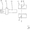
- FIG. 1 the beginning of the manufacturing process of a shoe sole is shown schematically.
- An extruder 18 plasticizes plastic material and applies it via an extrusion head 17 so that a plastic tube 2 closed over the entire circumference is produced. If this is long enough, it is introduced into a blow mold 3, which consists of two tool halves exists, which are moved towards one another in the direction of the double arrows and then enclose the plastic tube 2 in a known manner for the purpose of blow molding.
- a blow mold 3 which consists of two tool halves exists, which are moved towards one another in the direction of the double arrows and then enclose the plastic tube 2 in a known manner for the purpose of blow molding.
- injection molding of a plastic blank can alternatively be envisaged, which is then reshaped in the blow mold 3.
- a hollow sole body 4 (see Fig. Figures 2 and 3 ) produced, which provides a recording space in its interior.
- a first deformation tool 13 and a second deformation tool 15 are schematically indicated. These tools 13, 15 move towards one another in the direction of the arrow when the tool halves of the blow mold 3 are closed. The tools 13, 15 are used to create support structures 9 (see FIGS Figures 2 to 4 ) introduced into the hollow sole body 4.
- the hollow sole body 4 has an upper wall 5 and a lower wall 6 has, which are spaced apart from each other after the blow molding process and enclose the mentioned cavity between them.
- the deformation tools 13 and 15 are at the points that result from Figure 2 result, indentations 7 and 8 are introduced, namely indentation 7 by first deformation tool 13 and indentation 8 by second deformation tool 15.
- the indentation 7 has a closed end region 14, while the indentation 8 has an opening through the second deformation tool 15, which is axially end-needle-shaped. This opening is dimensioned in such a way that the indentation 7 with its closed end region 14 can at least partially enter it.
- the support structure 9 produced in this way prevents or impedes a relative displacement between the upper wall 5 and the lower wall 6 in the horizontal direction (when the shoe is used as intended, which has the shoe sole 1 in question).
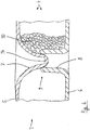
- plastic body 10 When the described hollow sole body 4 is completed, the cavity it encloses is filled with plastic body 10. This is in Figure 3 illustrated.
- a filling nozzle 19 is pushed into an opening 11 in the hollow sole body 4.
- Spherical or ellipsoidal plastic bodies 10 made of expanded thermoplastic polyurethane (E-TPU) are then filled into the hollow sole body 4 via the filling nozzle 19, optionally supported by compressed air, until the hollow body 4 is completely filled with plastic body 10.
- E-TPU expanded thermoplastic polyurethane
- plastic bodies 10 are filled into the cavity of the hollow sole body 4, as it were, as bulk goods and are placed in the cavity without being connected to one another. Accordingly, the plastic bodies 10 are free from any connection to one another.
- the plastic bodies 10 support each other after their filling of the hollow sole body 4, but are loosely arranged with respect to each other.
- the filling process can be supported at a second opening 12 of the hollow sole body and, if necessary, air can be evacuated from the interior of the hollow sole body 4 after completion of the same (see arrow at opening 12).
- the openings 11 and 12 can be closed with plastic bodies 10 after the filling process has been completed. In particular, welding of the openings is intended. This creates a hermetically sealed cavity in the shoe sole 1 which is filled with the loose plastic bodies 10.
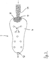
- FIG 2 Another preferred development of the method described is illustrated: Here a U-shaped insert 16 can be seen, which is inserted into the cavity of the blow mold 3 before the blow mold 3 is closed. By means of the blow molding process, the insert 16 is firmly connected (welded) to the plastic tube 2 or the hollow sole body 4.
- the insert 16 can be used to specifically influence the support function of the shoe sole 1.
- the insert 16 is preferably used as a heel shell, which supports the foot of the user of the shoe equipped with the shoe sole in the rear area and in particular in the area of the heel.
Landscapes
- Engineering & Computer Science (AREA)
- Manufacturing & Machinery (AREA)
- Mechanical Engineering (AREA)
- Chemical & Material Sciences (AREA)
- Materials Engineering (AREA)
- Footwear And Its Accessory, Manufacturing Method And Apparatuses (AREA)
- Blow-Moulding Or Thermoforming Of Plastics Or The Like (AREA)
- Moulds For Moulding Plastics Or The Like (AREA)
Description
- Die Erfindung betrifft ein Verfahren zur Herstellung einer Schuhsohle, insbesondere einer solchen für einen Sportschuh.
- Die Herstellung von Schuhsohlen insbesondere für Sportschuhe ist eine hinlänglich bekannte Technologie. Dabei wird angestrebt, nicht nur einen wirtschaftlichen Prozess für die Fertigung bereitzustellen, sondern auch die Möglichkeit zu haben, auf das Feder- und Dämpfverhalten der Schuhsohle und damit des Schuhs möglichst gut Einfluss nehmen zu können. Hierfür spielt auch das zum Einsatz kommende Material eine wesentliche Rolle.
- In der
US 2009/0013558 A1 wird ein Schuh beschrieben, bei dem die Schuhsohle aus unterschiedlichen Kunststoffen besteht, die miteinander verbunden sind, wobei unterschiedliche Polymermaterialien zum Einsatz kommen. In derWO 2007/082838 A1 wird beschrieben, dass für eine Schuhsohle auch expandiertes Thermoplastisches Polyurethan (E-TPU) vorteilhaft zum Einsatz kommen kann. In diesem Dokument sind auch detaillierte Informationen zu diesem Kunststoffmaterial vorhanden; insoweit wird ausdrücklich auf dieses Dokument Bezug genommen. - Auch in der
DE 10 2011 108 744 B4 wird ein Schuh beschrieben, bei dem E-TPU als Material für die Sohle eingesetzt wird. Hier wird weiter beschrieben, dass einzelne geschäumte Kunststoffkugeln aus diesem Material, die zumeist eine Abmessung von wenigen Millimetern haben, dadurch zur Sohle geformt werden, dass gemäß einer möglichen Verarbeitungsform in ein entsprechendes Werkzeug ein Bindemittel eingegeben wird, so dass die Kunststoffkugeln miteinander verbunden werden und den Formkörper der Sohle bilden. Nach einer anderen Vorgehensweise wird Wasserdampf unter definiertem Druck in ein Formwerkzeug eingegeben, in dem die Kunststoffkugeln eingebracht sind. Dabei kommt es zu einem partiellen Aufschmelzen des Kunststoffmaterials, so dass sich die Kunststoffkugeln stoffschlüssig miteinander verbinden und so den Formkörper der Sohle bilden. - Die damit erzielbaren Eigenschaften des Schuhs, insbesondere mit Blick auf dessen Feder- und Dämpfungsverhalten, sind nicht in jedem Falle voll befriedigend. Des weiteren ist der Herstellungsprozess der genannten Sohle mitunter relativ aufwendig und somit kostenintensiv.
- Aus der
EP 0 215 974 A1 ist es bekannt, einen hohlen Sohlenkörper für einen Schuh durch Blasformen zu fertigen. Eine ähnliche Lösung zeigt dieUS 2002/113342 A1 . Der in derUS 3 608 215 A beschriebene Schuh weist gleichermaßen eine Sohle mit einem Hohlraum auf. - Der Erfindung liegt daher die Aufgabe zugrunde, ein Verfahren bereitzustellen, mit dem eine Schuhsohle kostengünstig hergestellt und deren Feder- und Dämpfungsverhalten in einer gewünschten Weise eingestellt werden kann. Die Schuhsohle soll somit in wirtschaftlicher Weise und mit einfach einstellbaren Feder- und Dämpfungseigenschaften produziert werden können.
- Die Lösung dieser Aufgabe durch die Erfindung ist dadurch gekennzeichnet, dass das Verfahren die folgenden Schritte umfasst:
- a) Extrudieren eines Kunststoffschlauchs und Zuführen des Kunststoffschlauchs in eine Blasform oder Spritzgießen eines Kunststoffrohlings und Zuführen des Kunststoffrohlings in eine Blasform (3);
- b) Blasformen des Kunststoffschlauchs oder des Kunststoffrohlings zu einem Sohlen-Hohlkörper, wobei während des Blasformprozesses an sich gegenüberliegenden Wandungen des Sohlen-Hohlkörpers Einformungen eingebracht werden, so dass Teile der Wandungen in Kontakt miteinander gebracht werden und zwischen den sich gegenüberliegenden Wandungen eine Stützstruktur bilden;
- c) Entformen des blasgeformten Sohlen-Hohlkörpers aus der Blasform;
- d) Zumindest teilweises, vorzugsweise vollständiges, Füllen des blasgeformten Sohlen-Hohlkörpers mit Kunststoffkörpem, wobei die Kunststoffkörper durch eine erste Öffnung im Sohlen-Hohlkörper eingefüllt werden.
- Als Kunststoffkörper werden dabei insbesondere Kugeln, Ellipsoide oder Zylinder verwendet. Die Abmessungen der einzelnen Kunststoffkörper in den drei Raumrichtungen liegen bevorzugt zwischen 1 mm und 13 mm, besonders bevorzugt zwischen 3 mm und 6 mm. Die Kunststoffkörper bestehen dabei insbesondere aus geschäumtem Kunststoffmaterial.
- Als Material für die Kunststoffkörper kommt bevorzugt expandiertes thermoplastisches Polyurethan (E-TPU), expandiertes thermoplastisches Elastomer (E-TPE) (insbesondere expandiertes thermoplastischen Elastomer auf Olefinbasis (E-TPO)) und/oder expandiertes Polypropylen (EPP) zum Einsatz.
- Der Sohlen-Hohlkörper besteht indes bevorzugt aus thermoplastischem Polyurethan (TPU), aus thermoplastischem Elastomer (TPE), aus Polyamid (PA) und/oder aus Gummimaterial.
- Eine bevorzugte Weiterbildung des Verfahrens sieht vor, dass nach obigem Schritt d) ein Verschließen, insbesondere ein Verschweißen, der ersten Öffnung erfolgt.
- Weiterhin kann vorgesehen werden, dass während oder nach obigem Schritt d) ein Absaugen von Luft aus dem Sohlen-Hohlkörper erfolgt. Dies erfolgt bevorzugt über eine zweite Öffnung, die von der ersten Öffnung beabstandet ist.
- Die Kunststoffkörper werden dabei bevorzugt ohne Verbindung zueinander im Sohlen-Hohlkörper platziert. Demgemäß werden die einzelnen Kugeln oder Elipsoide nicht durch irgendwelche Maßnahmen miteinander verbunden, sondern sie sind lose im Sohlen-Hohlkörper platziert.
- Die Kunststoffkörper werden dabei bevorzugt in voller Packung und vorzugsweise unter Druck im Sohlen-Hohlkörper platziert.
- Die Herstellung der Stützstruktur erfolgt bevorzugt, indem in die eine Wandung mittels eines ersten Deformationswerkzeugs die eine Einformung mit geschlossenem Endbereich erzeugt wird und in die andere Wandung mittels eines zweiten Deformationswerkzeugs die andere Einformung mit offenem Endbereich erzeugt wird, wobei der geschlossene Endbereich der einen Einformung zum Eintritt in das offene Ende der zweiten anderen Einformung ausgebildet ist. Hierdurch wird in sehr vorteilhafter Weise ein Feder- bzw. Dämpfungselement nach Art eines Kolben-Zylinder-Systems realisiert. Bei bestimmungsgemäßer Benutzung des Schuhs, der mit der beschriebenen Schuhsohle ausgestattet ist, können sich somit Relativbewegungen zwischen den beiden Einformungen in vertikaler Richtung ergeben (wenn die Schuhsohle auf dem Boden steht). Durch die Wahl der Geometrie der beiden Einformungen und insbesondere des geschlossenen Endbereichs einerseits sowie der Öffnung in der anderen Einformung andererseits kann gezielt die Federkonstante der Sohle in vertikaler Richtung sowie deren Dämpfungsverhalten beeinflusst werden.
- Eine Weiterbildung des Verfahrens sieht vor, dass vor dem Schließen der Blasform und der Durchführung des obigen Schritts b) ein Einlegeteil in die Blasform eingelegt wird, so dass sich das Einlegeteil mit dem Sohlen-Hohlkörper während des Blasformvorgangs verbindet.
- Das Einlegeteil kann dabei durch einen Spritzgießvorgang vorgefertigt werden. Das Einlegeteil ist nach einer bevorzugten Ausgestaltung mit einer U-förmigen Gestalt versehen. Diese wird insbesondere als Fersenspange im hinteren Bereich der Schuhsohle platziert. Das Einlegeteil besteht dabei bevorzugt aus thermoplastischem Polyurethan (TPU).
- Möglich, wenngleich wegen des damit verbundenen höheren Fertigungsaufwands nicht bevorzugt, wäre es auch, dass durch den Blasformvorgang mehrere voneinander getrennte Hohlräume im Inneren des Sohlen-Hohlkörpers hergestellt werden, die dann mit jeweiligen Kunststoffkörpern gefüllt werden. Diese können gegebenenfalls dann auch unterschiedliche physikalische Eigenschaften haben, um die Feder- und Dämpfungseigenschaften der Schuhsohle gezielt beeinflussen zu können.
- Die Kunststoffkörper weisen bevorzugt eine Härte zwischen 75 bis 90 Shore A auf, vorzugsweise zwischen 80 und 85 Shore A. Sie haben bevorzugt eine Schüttdichte zwischen 100 und 300 kg/m3.
- Zu dem bevorzugt zum Einsatz kommenden expandierten thermoplastischen Polyurethan (E-TPU) für die Kunststoffkörper, die in den blasgeformten Sohlen-Hohlkörper eingebracht werden, sei folgendes erwähnt: Dieses Material ist an sich bekannt und wird in Schuhen eingesetzt. Es ist beispielsweise unter der Bezeichnung "PearlFoam" von der Huntsman International LLC oder unter der Bezeichnung "Infinergy" von der BASF SE erhältlich. Zu diesem Material wird ausdrücklich auf die
WO 2005/066250 A1 Bezug genommen, wo sich Details zu diesem Material, also zu expandierbaren thermoplastischen Polyurethanen und deren Herstellung finden. - Zum Vorbekanntsein von thermoplastischem Elastomer auf Urethanbasis sei weiterhin ausdrücklich auf die
WO 2010/010010 A1 hingewiesen, in der ein expandierbarer, treibmittelhaltiger thermoplastischer Polymer-Blend offenbart wird, der thermoplastisches Polyurethan und Styrolpolymerisat enthält. Der Polymer-Blend kann dabei mindestens ein weiteres thermoplastisches Polymer enthalten. Als weiteres thermoplastisches Polymer kommt insbesondere Polyamid (PA), Polymethylmethacrylat (PMMA), Polycarbonat (PC), Polyethylen (PE), Polypropylen (PP), Polyvinylchlorid (PVC), Cellulose bzw. Polyoxymethylen (POM) in Frage. - Gemäß der Erfindung werden also in einem blasgeformten Sohlen-Hohlkörper insbesondere expandierte Kunststoffschaum-Kugeln oder -Ellipsoide (eventuell auch zylindrisch geformte Körper) unter Verwendung insbesondere von E-TPU, E-TPE oder EPP (um beispielsweise sehr leichte Sohlen zu fertigen) eingesetzt, die in den geschaffenen Hohlraum im Sohlen-Hohlkörper gefüllt werden (besagter Sohlen-Hohlkörper kann auch als vorgefertigter "Käfig" für die Kugeln bzw. Ellipsoide bezeichnet werden).
- Die angesprochene Stützstruktur erlaubt, dass die Sohle bei bestimmungsgemäßer Benutzung unter Belastung den Fuß optimal stützt. Dies ist unter dem Aspekt wesentlich, da ansonsten die sich im Inneren des Sohlen-Hohlraum befindlichen Kunststoffkörper infolge dessen, dass sie nicht miteinander verbunden sondern lose angeordnet sind, möglicherweise eine unzureichende Stützfunktion für den Fuß bieten würden.
- Die Kugeln, Ellipsoide bzw. Zylinder, vorzugsweise aus E-TPU, beeinflussen wesentlich die Dämpfung des Schuhs, so dass das Sohlenteil mit dem befüllten Hohlraum bevorzugt als Zwischensohle zum Einsatz kommt.
- Die Sohle kann mittels Vernähen oder Verkleben mit dem Schuhoberteil (Schuhschaft) verbunden werden, was als solches bekannt ist.
- Vorstehend ist die Produktion der Sohle als komplettes Formteil beschrieben. Die Erfindung kann natürlich genauso auch zum Einsatz kommen, wenn lediglich ein Teil der Sohle wie beschrieben hergestellt und gegebenenfalls mit einem weiteren Sohlenteil verbunden wird.
- Wenngleich das Extrudieren eines Kunststoffschlauchs und dessen unmittelbares Zuführen im noch warmen Zustand in die Blasform bevorzugt ist, kommt alternativ - wie oben angegeben - auch ein Spritzgießen eines Kunststoffrohlings infrage, der dann der Blasform zugeführt wird. In diesem Falle wird typischerweise zunächst der Spritzgießprozess für den Kunststoffrohling durchgeführt; wenn der Kunststoffrohling zur Blasformmaschine verbracht ist und in dieser blasgeformt werden soll, wird er dann wieder vorher erwärmt, um zum Sohlen-Hohlkörper verformt werden zu können.
- In der Zeichnung ist ein Ausführungsbeispiel der Erfindung dargestellt. Es zeigen:
- Fig. 1
- schematisch einen ersten Prozessschritt der erfindungsgemäßen Herstellung einer Schuhsohle,
- Fig. 2
- die Draufsicht auf die Schuhsohle nach der Durchführung des Prozessschrittes gemäß
Figur 1 , wobei der Sohlen-Hohlkörper der Schuhsohle noch nicht befüllt ist, - Fig. 3
- schematisch den nachfolgenden Prozessschritt, gemäß dem der Sohlen-Hohlkörper der Schuhsohle mit Kunststoffkörpern befüllt wird, und
- Fig. 4
- den Schnitt A-B gemäß
Figur 2 . - In
Figur 1 ist schematisch der Beginn des Herstellungsprozesses einer Schuhsohle dargestellt. Ein Extruder 18 plastifiziert Kunststoffmaterial und bringt es über einen Extrusionskopf 17 aus, so dass ein über den gesamten Umfang geschlossener Kunststoffschlauch 2 produziert wird. Ist dieser lang genug, wird er in eine Blasform 3 eingebracht, die aus zwei Werkzeughälften besteht, die in Richtung der Doppelpfeile aufeinander zu bewegt werden und dann in bekannter Weise den Kunststoffschlauch 2 zwecks Blasformen einschließen. - Wie bereits erwähnt, kann alternativ auch ein Spritzgießen eines Kunststoffrohlings ins Auge gefasst werden, der dann in der Blasform 3 umgeformt wird.
- Durch den Blasformvorgang wird ein Sohlen-Hohlkörper 4 (s.
Figuren 2 und3 ) hergestellt, der in seinem Inneren einen Aufnahmeraum bereitstellt. - Schematisch angedeutet sind ein erstes Deformationswerkzeug 13 und ein zweites Deformationswerkzeug 15. Diese Werkzeuge 13, 15 fahren in Pfeilrichtung aufeinander zu, wenn die Werkzeughälften der Blasform 3 geschlossen sind. Durch die Werkzeuge 13, 15 werden Stützstrukturen 9 (siehe die
Figuren 2 bis 4 ) in den Sohlen-Hohlkörper 4 eingebracht. - Von den Werkzeugen 13, 15 ist eine Anzahl vorhanden, wenngleich in
Figur 1 nur ein einziges Paar der Werkzeuge 13, 15 dargestellt ist. - Wie sich aus
Figur 2 ergibt, wurden vorliegend eine Anzahl der erwähnten Stützstrukturen 9, die nachfolgend noch näher beschrieben werden, hergestellt. Sie haben den Zweck, über die Aufstandsfläche des Fußes auf der Oberfläche der Schuhsohle 1 an gewünschten Stellen eine Stützfunktion zu bieten, so dass bei Aufgabe des Körpergewichts des Trägers des Schuhs die Schuhsohle 1 nicht in unkontrollierter Weise seitlich ausweicht. - Details zur Stützstruktur 9 ergeben sich aus
Figur 4 . Hier ist zu erkennen, dass der Sohlen-Hohlkörper 4 eine obere Wandung 5 und eine untere Wandung 6 aufweist, die sich nach Durchführung des Blasformvorgangs beabstandet gegenüber liegen und zwischen sich den erwähnten Hohlraum einschließen. Durch die Deformationswerkzeuge 13 und 15 werden an den Stellen, die sich ausFigur 2 ergeben, Einformungen 7 und 8 eingebracht, nämlich durch das erste Deformationswerkzeug 13 die Einformung 7 und durch das zweite Deformationswerkzeug 15 die Einformung 8. - Wie zu erkennen ist, weist die Einformung 7 einen geschlossenen Endbereich 14 auf, während die Einformung 8 durch das axial endseitig nadelförmig ausgebildete zweite Deformationswerkzeug 15 eine Öffnung aufweist. Diese Öffnung ist so dimensioniert, dass die Einformung 7 mit ihrem geschlossenen Endbereich 14 zumindest teilweise in diese eintreten kann.
- Die so hergestellte Stützstruktur 9 verhindert bzw. erschwert eine relative Verschiebung zwischen der oberen Wandung 5 und der unteren Wandung 6 in horizontale Richtung (bei bestimmungsgemäßer Verwendung des Schuhs, der die in Rede stehende Schuhsohle 1 aufweist).
- Ist der beschriebene Sohlen-Hohlkörper 4 insoweit fertig gestellt, wird der Hohlraum, den er einschließt, mit Kunststoffkörper 10 gefüllt. Dies ist in
Figur 3 illustriert. Hierzu wird eine Einfülldüse 19 in eine Öffnung 11 im Sohlen-Hohlkörper 4 eingeschoben. Über die Einfülldüse 19 werden dann, gegebenenfalls unterstützt durch Druckluft, kugelförmige oder ellipsoide Kunststoffkörper 10 aus expandiertem thermoplastischen Polyurethan (E-TPU) in den Sohlen-Hohlkörper 4 gefüllt, bis dieser vollständig mit Kunststoffkörper 10 gefüllt ist. Zu dem Material der Kunststoffkörper 10 sind oben bereits Hinweise auf entsprechende Publikationen angegeben. - Wesentlich ist, dass die Kunststoffkörper 10 in den Hohlraum des Sohlen-Hohlkörpers 4 quasi als Schüttgut eingefüllt und im Hohlraum unverbunden miteinander platziert sind. Demgemäß sind die Kunststoffkörper 10 frei von einer Verbindung untereinander. Die Kunststoffkörper 10 stützen sich nach ihrer Befüllung des Sohlen-Hohlkörper 4 zwar gegeneinander ab, sind aber lose zueinander angeordnet.
- Hierdurch kann nicht nur das Dämpfungsverhalten der Sohle und damit des Schuhs sehr vorteilhaft beeinflusst werden; gleichzeitig ist auch der Herstellungsprozess einfach und kostengünstig durchführbar.
- Durch das Absaugen von Luft, d. h. Anlegen eines Vakuums, an einer zweiten Öffnung 12 des Sohlen-Hohlkörper kann der Füllvorgang unterstützt und gegebenenfalls nach Abschluss desselben Luft aus dem Inneren des Sohlen-Hohlkörpers 4 evakuiert werden (siehe Pfeil bei der Öffnung 12).
- Die Öffnungen 11 bzw. 12 können nach Abschluss des Füllprozesses mit Kunststoffkörpern 10 verschlossen werden. Hierbei ist insbesondere an ein Verschweißen der Öffnungen gedacht. So entsteht ein hermetisch abgeschlossener Hohlraum in der Schuhsohle 1, der mit den losen Kunststoffkörpern 10 gefüllt ist.
- Im Zusammenwirken mit der Stützstruktur 9 ergibt sich die Möglichkeit, die Feder- und Dämpfungseigenschaften der Schuhsohle in gewissen Grenzen beliebig zu beeinflussen und dennoch dafür zu sorgen, dass bei der bestimmungsgemäßen Benutzung des Schuhs, der mit der Schuhsohle versehen ist, ein guter Halt für den Fuß bei guter Stabilität der Sohle gegeben ist.
- In
Figur 2 ist noch eine bevorzugte Weiterbildung des beschriebenen Verfahrens illustriert: Hier ist ein U-förmiges Einlegeteil 16 zu sehen, das vor dem Schließen der Blasform 3 in die Kavität derselben eingelegt wird. Durch den Blasformvorgang wird das Einlegeteil 16 fest mit dem Kunststoffschlauch 2 bzw. dem Sohlen-Hohlkörper 4 verbunden (verschweißt). - Das Einlegeteil 16 kann genutzt werden, um gezielt die Stützfunktion der Schuhsohle 1 zu beeinflussen. Bevorzugt wird das Einlegeteil 16 als Fersenschale benutzt, die im hinteren Bereich und namentlich im Bereich der Ferse den Fuß des Benutzers des mit der Schuhsohle ausgestatteten Schuhs stützt.
-
- 1
- Schuhsohle
- 2
- Kunststoffschlauch
- 3
- Blasform
- 4
- Sohlen-Hohlkörper
- 5
- Wandung
- 6
- Wandung
- 7
- Einformung
- 8
- Einformung
- 9
- Stützstruktur
- 10
- Kunststoffkörper
- 11
- erste Öffnung
- 12
- zweite Öffnung
- 13
- erstes Deformationswerkzeug
- 14
- geschlossener Endbereich
- 15
- zweites Deformationswerkzeug
- 16
- Einlegeteil
- 17
- Extrusionskopf
- 18
- Extruder
- 19
- Einfülldüse
Claims (15)
- Verfahren zur Herstellung einer Schuhsohle (1), umfassend die Schritte:a) Extrudieren eines Kunststoffschlauchs (2) und Zuführen des Kunststoffschlauchs (2) in eine Blasform (3) oder Spritzgießen eines Kunststoffrohlings und Zuführen des Kunststoffrohlings in eine Blasform (3);b) Blasformen des Kunststoffschlauchs (2) oder des Kunststoffrohlings zu einem Sohlen-Hohlkörper (4), wobei während des Blasformprozesses an sich gegenüberliegenden Wandungen (5, 6) des Sohlen-Hohlkörpers (4) Einformungen (7, 8) eingebracht werden, so dass Teile der Wandungen (7, 8) in Kontakt miteinander gebracht werden und zwischen den sich gegenüberliegenden Wandungen (7, 8) eine Stützstruktur (9) bilden;c) Entformen des blasgeformten Sohlen-Hohlkörpers (4) aus der Blasform (3);d) Zumindest teilweises, vorzugsweise vollständiges, Füllen des blasgeformten Sohlen-Hohlkörpers (4) mit Kunststoffkörpern (10), wobei die Kunststoffkörper (10) durch eine erste Öffnung (11) im Sohlen-Hohlkörper (4) eingefüllt werden.
- Verfahren nach Anspruch 1, dadurch gekennzeichnet, dass als Kunststoffkörper (10) Kugeln, Ellipsoide oder Zylinder verwendet werden.
- Verfahren nach Anspruch 2, dadurch gekennzeichnet, dass die Abmessungen der einzelnen Kunststoffkörper (10) in den drei Raumrichtungen zwischen 1 mm und 13 mm betragen, vorzugsweise zwischen 3 mm und 6 mm.
- Verfahren nach einem der Ansprüche 1 bis 3, dadurch gekennzeichnet, dass die Kunststoffkörper (10) aus geschäumtem Kunststoffmaterial bestehen.
- Verfahren nach einem der Ansprüche 1 bis 4, dadurch gekennzeichnet, dass die Kunststoffkörper (10) aus expandiertem thermoplastischen Polyurethan (E-TPU), aus expandiertem thermoplastischen Elastomer (E-TPE), insbesondere aus expandiertem thermoplastischen Elastomer auf Olefinbasis (E-TPO), und/oder aus expandiertem Polypropylen (EPP) bestehen.
- Verfahren nach einem der Ansprüche 1 bis 5, dadurch gekennzeichnet, dass der Sohlen-Hohlkörper (4) aus thermoplastischem Polyurethan (TPU), aus thermoplastischem Elastomer (TPE), aus Polyamid (PA) und/oder aus Gummimaterial besteht.
- Verfahren nach einem der Ansprüche 1 bis 6, dadurch gekennzeichnet, dass nach Schritt d) gemäß Anspruch 1 ein Verschließen, insbesondere ein Verschweißen, der ersten Öffnung (11) erfolgt.
- Verfahren nach einem der Ansprüche 1 bis 7, dadurch gekennzeichnet, dass während oder nach Schritt d) gemäß Anspruch 1 ein Absaugen von Luft aus dem Sohlen-Hohlkörper (4) erfolgt, insbesondere über eine zweite Öffnung (12), die von der ersten Öffnung (11) beabstandet ist.
- Verfahren nach einem der Ansprüche 1 bis 8, dadurch gekennzeichnet, dass die Kunststoffkörper (10) ohne Verbindung zueinander im Sohlen-Hohlkörper (4) platziert werden.
- Verfahren nach einem der Ansprüche 1 bis 9, dadurch gekennzeichnet, dass die Kunststoffkörper (10) in voller Packung und vorzugsweise unter Druck im Sohlen-Hohlkörper (4) platziert werden.
- Verfahren nach einem der Ansprüche 1 bis 10, dadurch gekennzeichnet, dass die Herstellung der Stützstruktur (9) erfolgt, indem in die eine Wandung (5) mittels eines ersten Deformationswerkzeugs (13) die eine Einformung (7) mit geschlossenem Endbereich (14) erzeugt wird und in die andere Wandung (6) mittels eines zweiten Deformationswerkzeugs (15) die andere Einformung (8) mit offenem Endbereich erzeugt wird, wobei der geschlossene Endbereich (14) der einen Einformung (7) zum Eintritt in das offene Ende der anderen Einformung (8) ausgebildet ist.
- Verfahren nach einem der Ansprüche 1 bis 11, dadurch gekennzeichnet, dass vor dem Schließen der Blasform (3) und Durchführung des Schritts b) gemäß Anspruch 1 ein Einlegeteil (16) in die Blasform (3) eingelegt wird, so dass sich das Einlegeteil (16) mit dem Sohlen-Hohlkörper (4) während des Blasformvorgangs verbindet.
- Verfahren nach Anspruch 12, dadurch gekennzeichnet, dass das Einlegeteil (16) durch einen Spritzgießvorgang vorgefertigt wird.
- Verfahren nach Anspruch 12 oder 13, dadurch gekennzeichnet, dass das Einlegeteil (16) eine U-förmige Gestalt aufweist.
- Verfahren nach einem der Ansprüche 12 bis 14, dadurch gekennzeichnet, dass das Einlegeteil (16) aus thermoplastischem Polyurethan (TPU) besteht.
Applications Claiming Priority (1)
| Application Number | Priority Date | Filing Date | Title |
|---|---|---|---|
| PCT/EP2016/002066 WO2018103811A1 (de) | 2016-12-08 | 2016-12-08 | Verfahren zur herstellung einer schuhsohle |
Publications (2)
| Publication Number | Publication Date |
|---|---|
| EP3551422A1 EP3551422A1 (de) | 2019-10-16 |
| EP3551422B1 true EP3551422B1 (de) | 2020-11-11 |
Family
ID=57737683
Family Applications (1)
| Application Number | Title | Priority Date | Filing Date |
|---|---|---|---|
| EP16822379.0A Active EP3551422B1 (de) | 2016-12-08 | 2016-12-08 | Verfahren zur herstellung einer schuhsohle |
Country Status (6)
| Country | Link |
|---|---|
| US (2) | US10856606B2 (de) |
| EP (1) | EP3551422B1 (de) |
| JP (1) | JP6756851B2 (de) |
| KR (1) | KR102155862B1 (de) |
| CN (1) | CN109070433B (de) |
| WO (1) | WO2018103811A1 (de) |
Families Citing this family (15)
| Publication number | Priority date | Publication date | Assignee | Title |
|---|---|---|---|---|
| USD953709S1 (en) | 1985-08-29 | 2022-06-07 | Puma SE | Shoe |
| USD910290S1 (en) | 2017-09-14 | 2021-02-16 | Puma SE | Shoe |
| USD855953S1 (en) | 2017-09-14 | 2019-08-13 | Puma SE | Shoe sole element |
| USD911682S1 (en) | 2017-09-14 | 2021-03-02 | Puma SE | Shoe |
| USD911683S1 (en) | 2017-09-14 | 2021-03-02 | Puma SE | Shoe |
| USD850766S1 (en) | 2017-01-17 | 2019-06-11 | Puma SE | Shoe sole element |
| CN110913715B (zh) | 2017-08-11 | 2022-05-27 | 彪马欧洲股份公司 | 鞋的生产方法 |
| USD975417S1 (en) | 2017-09-14 | 2023-01-17 | Puma SE | Shoe |
| EP3784086B1 (de) | 2018-04-27 | 2021-06-16 | Puma Se | Schuh, insbesondere sportschuh |
| WO2019214814A1 (de) | 2018-05-08 | 2019-11-14 | Puma SE | Sohle eines schuhs, insbesondere eines sportschuhs |
| JP7114743B2 (ja) | 2018-05-08 | 2022-08-08 | プーマ エス イー | 靴、とりわけ運動靴のソールを製造するための方法 |
| ES2941984T3 (es) | 2018-12-18 | 2023-05-29 | Puma SE | Zapato, en particular zapato deportivo, y procedimiento para su fabricación |
| US12478134B2 (en) | 2019-10-21 | 2025-11-25 | Puma SE | Article of footwear |
| USD944504S1 (en) | 2020-04-27 | 2022-03-01 | Puma SE | Shoe |
| US12109775B2 (en) | 2021-12-22 | 2024-10-08 | Puma SE | Method for producing a sole of a shoe |
Family Cites Families (24)
| Publication number | Priority date | Publication date | Assignee | Title |
|---|---|---|---|---|
| US3325920A (en) * | 1964-04-27 | 1967-06-20 | Rosemount Eng Co Ltd | Ski boot |
| US3608215A (en) * | 1969-06-14 | 1971-09-28 | Tatsuo Fukuoka | Footwear |
| US4658515A (en) * | 1985-02-05 | 1987-04-21 | Oatman Donald S | Heat insulating insert for footwear |
| AU564808B2 (en) * | 1985-08-23 | 1987-08-27 | Huang, I-C. | Manufacturing shoe soles with an air cushion |
| JPS6379705U (de) * | 1986-11-15 | 1988-05-26 | ||
| US5392534A (en) * | 1992-10-23 | 1995-02-28 | Grim; Tracy E. | Vacuum formed conformable shoe |
| US20020113342A1 (en) * | 1999-09-17 | 2002-08-22 | Tsai Shuang Chu | Method of making an elastic pad |
| US7229518B1 (en) * | 2000-11-02 | 2007-06-12 | Nike, Inc. | Process for improving interfacial adhesion in a laminate |
| USD460852S1 (en) * | 2001-04-12 | 2002-07-30 | Candie's, Inc. | Bean bag shoe lower |
| JP2002306280A (ja) | 2001-04-19 | 2002-10-22 | Apas:Kk | 圧力分散体 |
| DE10326138A1 (de) * | 2003-06-06 | 2004-12-23 | Basf Ag | Verfahren zur Herstellung von expandierbaren thermoplastischen Elastomeren |
| US7086179B2 (en) * | 2003-12-23 | 2006-08-08 | Nike, Inc. | Article of footwear having a fluid-filled bladder with a reinforcing structure |
| DE102004001204A1 (de) | 2004-01-06 | 2005-09-08 | Basf Ag | Verfahren zur Herstellung von Schuhen |
| US7484318B2 (en) * | 2004-06-15 | 2009-02-03 | Kenneth Cole Productions (Lic), Inc. | Therapeutic shoe sole design, method for manufacturing the same, and products constructed therefrom |
| US20060130363A1 (en) * | 2004-12-17 | 2006-06-22 | Michael Hottinger | Shoe sole with a loose fill comfort support system |
| EP1979401B1 (de) | 2006-01-18 | 2010-09-29 | Basf Se | Schaumstoffe auf basis thermoplastischer polyurethane |
| WO2008012809A2 (en) * | 2006-07-24 | 2008-01-31 | Naalei Sof Haderech Ltd. | Adaptable orthopedic insoles |
| US7941941B2 (en) | 2007-07-13 | 2011-05-17 | Nike, Inc. | Article of footwear incorporating foam-filled elements and methods for manufacturing the foam-filled elements |
| WO2010010010A1 (de) | 2008-07-25 | 2010-01-28 | Basf Se | Thermoplastische polymer blends auf der basis von thermoplastischem polyurethan und styrolpolymerisat, daraus hergestellte schaumstoffe und zugehörige herstellungsverfahren |
| NL2003367C2 (en) * | 2009-08-20 | 2011-02-22 | Sara Lee De Nv | Cushioning element, footwear, insole, deformable filling, and envelope. |
| DE102010046278A1 (de) * | 2010-06-28 | 2011-02-24 | Stuart Wolfe | Schuh mit einem Schuh-Oberteil und einer Sohle |
| DE102011108744B4 (de) * | 2011-07-28 | 2014-03-13 | Puma SE | Verfahren zur Herstellung einer Sohle oder eines Sohlenteils eines Schuhs |
| EP3226710B1 (de) * | 2014-12-02 | 2022-04-27 | NIKE Innovate C.V. | Sohlenstruktur mit hohlen polymerkörpern für einen schuhwerkartikel und herstellungsverfahren dafür |
| JP6679363B2 (ja) * | 2015-03-23 | 2020-04-15 | アディダス アーゲー | ソールおよびシューズ |
-
2016
- 2016-12-08 EP EP16822379.0A patent/EP3551422B1/de active Active
- 2016-12-08 CN CN201680084903.XA patent/CN109070433B/zh active Active
- 2016-12-08 KR KR1020187031607A patent/KR102155862B1/ko active Active
- 2016-12-08 US US16/095,239 patent/US10856606B2/en active Active
- 2016-12-08 WO PCT/EP2016/002066 patent/WO2018103811A1/de not_active Ceased
- 2016-12-08 JP JP2018555868A patent/JP6756851B2/ja active Active
-
2020
- 2020-12-07 US US17/113,690 patent/US20210085022A1/en not_active Abandoned
Non-Patent Citations (1)
| Title |
|---|
| None * |
Also Published As
| Publication number | Publication date |
|---|---|
| US20190133251A1 (en) | 2019-05-09 |
| JP2019518624A (ja) | 2019-07-04 |
| WO2018103811A1 (de) | 2018-06-14 |
| US20210085022A1 (en) | 2021-03-25 |
| JP6756851B2 (ja) | 2020-09-16 |
| CN109070433A (zh) | 2018-12-21 |
| EP3551422A1 (de) | 2019-10-16 |
| KR20180128477A (ko) | 2018-12-03 |
| KR102155862B1 (ko) | 2020-09-15 |
| US10856606B2 (en) | 2020-12-08 |
| CN109070433B (zh) | 2021-06-04 |
Similar Documents
| Publication | Publication Date | Title |
|---|---|---|
| EP3551422B1 (de) | Verfahren zur herstellung einer schuhsohle | |
| EP3664656B1 (de) | Verfahren zur herstellung eines schuhs | |
| EP3386334B1 (de) | Schuh, insbesondere sportschuh | |
| DE102013202291B4 (de) | Dämpfungselement für Sportbekleidung und Schuh mit einem solchen Dämpfungselement | |
| EP2645898B1 (de) | Verfahren zur herstellung eines schuhs | |
| EP3790732B1 (de) | Verfahren zur herstellung einer sohle eines schuhs, insbesondere eines sportschuhs | |
| EP1025970A2 (de) | Giessform und ihre Verwendung | |
| DE102016225335B4 (de) | Sohle für einen Schuh, Verfahren und Vorrichtung zu deren Herstellung sowie Schuh mit einer solchen Sohle | |
| DE4213263A1 (de) | Verfahren und vorrichtung zum herstellen von geschaeumten, geformten thermoplastischen gegenstaenden sowie auf diese weise hergestellte gegenstaende | |
| EP3897268A1 (de) | Schuh, insbesondere sportschuh, und verfahren zu seiner herstellung | |
| DE10048399A1 (de) | Inmould-Formschäumvorrichtung und -verfahren und formgeschäumte Artikel | |
| WO2006045813A1 (de) | Verfahren zur herstellung eines mit einer behälteröffnung versehenen behälters und nach diesem verfahren hergestellter behälter | |
| DE102018212760A1 (de) | Injection-molding method | |
| DE2318521A1 (de) | Verfahren zur herstellung von polstersohlen-schuhen sowie leisten zur durchfuehrung des verfahrens | |
| DE3813993A1 (de) | Verfahren und vorrichtung zum herstellen von schuhsohlen aus thermoplastischem material und zum anformen an schuhschaefte | |
| CH707854A2 (de) | Extrusionsblasgeformte Tube. | |
| EP3576562B1 (de) | Schuh, insbesondere sportschuh | |
| DE102017118826A1 (de) | Verfahren zur Herstellung eines Bauteils aus einer als Hohlkörper ausgebildeten Preform aus Kunststoff | |
| EP2595887B1 (de) | Verfahren und vorrichtung zum herstellen und befüllen von behältern aus thermoplastischem kunststoff | |
| DE10103787B4 (de) | Doppelwandiger Behälter aus Kunststoff sowie ein Verfahren zur Herstellung desselben | |
| DE60101787T2 (de) | Verfahren und vorrichtung zur herstellung von behältern | |
| EP4514588B1 (de) | Spenderbehälter und verfahren zur herstellung eines spenderbehälters | |
| DE202005001006U1 (de) | Schuh, insbesondere Sportschuh | |
| CH718924A1 (de) | Streckgeblasener Kunststoffbehälter mit einem am Behälterkörper ausgebildeten Handgriff und Verfahren zum Herstellen. | |
| DE4331183C1 (de) | Schuhsohle |
Legal Events
| Date | Code | Title | Description |
|---|---|---|---|
| STAA | Information on the status of an ep patent application or granted ep patent |
Free format text: STATUS: UNKNOWN |
|
| STAA | Information on the status of an ep patent application or granted ep patent |
Free format text: STATUS: THE INTERNATIONAL PUBLICATION HAS BEEN MADE |
|
| PUAI | Public reference made under article 153(3) epc to a published international application that has entered the european phase |
Free format text: ORIGINAL CODE: 0009012 |
|
| STAA | Information on the status of an ep patent application or granted ep patent |
Free format text: STATUS: REQUEST FOR EXAMINATION WAS MADE |
|
| 17P | Request for examination filed |
Effective date: 20190708 |
|
| AK | Designated contracting states |
Kind code of ref document: A1 Designated state(s): AL AT BE BG CH CY CZ DE DK EE ES FI FR GB GR HR HU IE IS IT LI LT LU LV MC MK MT NL NO PL PT RO RS SE SI SK SM TR |
|
| AX | Request for extension of the european patent |
Extension state: BA ME |
|
| DAV | Request for validation of the european patent (deleted) | ||
| DAX | Request for extension of the european patent (deleted) | ||
| GRAP | Despatch of communication of intention to grant a patent |
Free format text: ORIGINAL CODE: EPIDOSNIGR1 |
|
| STAA | Information on the status of an ep patent application or granted ep patent |
Free format text: STATUS: GRANT OF PATENT IS INTENDED |
|
| INTG | Intention to grant announced |
Effective date: 20200630 |
|
| GRAJ | Information related to disapproval of communication of intention to grant by the applicant or resumption of examination proceedings by the epo deleted |
Free format text: ORIGINAL CODE: EPIDOSDIGR1 |
|
| STAA | Information on the status of an ep patent application or granted ep patent |
Free format text: STATUS: REQUEST FOR EXAMINATION WAS MADE |
|
| GRAP | Despatch of communication of intention to grant a patent |
Free format text: ORIGINAL CODE: EPIDOSNIGR1 |
|
| STAA | Information on the status of an ep patent application or granted ep patent |
Free format text: STATUS: GRANT OF PATENT IS INTENDED |
|
| GRAS | Grant fee paid |
Free format text: ORIGINAL CODE: EPIDOSNIGR3 |
|
| GRAA | (expected) grant |
Free format text: ORIGINAL CODE: 0009210 |
|
| STAA | Information on the status of an ep patent application or granted ep patent |
Free format text: STATUS: THE PATENT HAS BEEN GRANTED |
|
| INTC | Intention to grant announced (deleted) | ||
| INTG | Intention to grant announced |
Effective date: 20200925 |
|
| AK | Designated contracting states |
Kind code of ref document: B1 Designated state(s): AL AT BE BG CH CY CZ DE DK EE ES FI FR GB GR HR HU IE IS IT LI LT LU LV MC MK MT NL NO PL PT RO RS SE SI SK SM TR |
|
| REG | Reference to a national code |
Ref country code: GB Ref legal event code: FG4D Free format text: NOT ENGLISH |
|
| REG | Reference to a national code |
Ref country code: CH Ref legal event code: EP |
|
| REG | Reference to a national code |
Ref country code: AT Ref legal event code: REF Ref document number: 1333030 Country of ref document: AT Kind code of ref document: T Effective date: 20201115 |
|
| REG | Reference to a national code |
Ref country code: DE Ref legal event code: R096 Ref document number: 502016011706 Country of ref document: DE |
|
| REG | Reference to a national code |
Ref country code: IE Ref legal event code: FG4D Free format text: LANGUAGE OF EP DOCUMENT: GERMAN |
|
| REG | Reference to a national code |
Ref country code: NL Ref legal event code: MP Effective date: 20201111 |
|
| PG25 | Lapsed in a contracting state [announced via postgrant information from national office to epo] |
Ref country code: NO Free format text: LAPSE BECAUSE OF FAILURE TO SUBMIT A TRANSLATION OF THE DESCRIPTION OR TO PAY THE FEE WITHIN THE PRESCRIBED TIME-LIMIT Effective date: 20210211 Ref country code: PT Free format text: LAPSE BECAUSE OF FAILURE TO SUBMIT A TRANSLATION OF THE DESCRIPTION OR TO PAY THE FEE WITHIN THE PRESCRIBED TIME-LIMIT Effective date: 20210311 Ref country code: RS Free format text: LAPSE BECAUSE OF FAILURE TO SUBMIT A TRANSLATION OF THE DESCRIPTION OR TO PAY THE FEE WITHIN THE PRESCRIBED TIME-LIMIT Effective date: 20201111 Ref country code: GR Free format text: LAPSE BECAUSE OF FAILURE TO SUBMIT A TRANSLATION OF THE DESCRIPTION OR TO PAY THE FEE WITHIN THE PRESCRIBED TIME-LIMIT Effective date: 20210212 Ref country code: FI Free format text: LAPSE BECAUSE OF FAILURE TO SUBMIT A TRANSLATION OF THE DESCRIPTION OR TO PAY THE FEE WITHIN THE PRESCRIBED TIME-LIMIT Effective date: 20201111 |
|
| PG25 | Lapsed in a contracting state [announced via postgrant information from national office to epo] |
Ref country code: BG Free format text: LAPSE BECAUSE OF FAILURE TO SUBMIT A TRANSLATION OF THE DESCRIPTION OR TO PAY THE FEE WITHIN THE PRESCRIBED TIME-LIMIT Effective date: 20210211 Ref country code: IS Free format text: LAPSE BECAUSE OF FAILURE TO SUBMIT A TRANSLATION OF THE DESCRIPTION OR TO PAY THE FEE WITHIN THE PRESCRIBED TIME-LIMIT Effective date: 20210311 Ref country code: LV Free format text: LAPSE BECAUSE OF FAILURE TO SUBMIT A TRANSLATION OF THE DESCRIPTION OR TO PAY THE FEE WITHIN THE PRESCRIBED TIME-LIMIT Effective date: 20201111 Ref country code: PL Free format text: LAPSE BECAUSE OF FAILURE TO SUBMIT A TRANSLATION OF THE DESCRIPTION OR TO PAY THE FEE WITHIN THE PRESCRIBED TIME-LIMIT Effective date: 20201111 Ref country code: SE Free format text: LAPSE BECAUSE OF FAILURE TO SUBMIT A TRANSLATION OF THE DESCRIPTION OR TO PAY THE FEE WITHIN THE PRESCRIBED TIME-LIMIT Effective date: 20201111 |
|
| REG | Reference to a national code |
Ref country code: LT Ref legal event code: MG9D |
|
| PG25 | Lapsed in a contracting state [announced via postgrant information from national office to epo] |
Ref country code: HR Free format text: LAPSE BECAUSE OF FAILURE TO SUBMIT A TRANSLATION OF THE DESCRIPTION OR TO PAY THE FEE WITHIN THE PRESCRIBED TIME-LIMIT Effective date: 20201111 |
|
| PG25 | Lapsed in a contracting state [announced via postgrant information from national office to epo] |
Ref country code: RO Free format text: LAPSE BECAUSE OF FAILURE TO SUBMIT A TRANSLATION OF THE DESCRIPTION OR TO PAY THE FEE WITHIN THE PRESCRIBED TIME-LIMIT Effective date: 20201111 Ref country code: SK Free format text: LAPSE BECAUSE OF FAILURE TO SUBMIT A TRANSLATION OF THE DESCRIPTION OR TO PAY THE FEE WITHIN THE PRESCRIBED TIME-LIMIT Effective date: 20201111 Ref country code: EE Free format text: LAPSE BECAUSE OF FAILURE TO SUBMIT A TRANSLATION OF THE DESCRIPTION OR TO PAY THE FEE WITHIN THE PRESCRIBED TIME-LIMIT Effective date: 20201111 Ref country code: CZ Free format text: LAPSE BECAUSE OF FAILURE TO SUBMIT A TRANSLATION OF THE DESCRIPTION OR TO PAY THE FEE WITHIN THE PRESCRIBED TIME-LIMIT Effective date: 20201111 Ref country code: LT Free format text: LAPSE BECAUSE OF FAILURE TO SUBMIT A TRANSLATION OF THE DESCRIPTION OR TO PAY THE FEE WITHIN THE PRESCRIBED TIME-LIMIT Effective date: 20201111 Ref country code: SM Free format text: LAPSE BECAUSE OF FAILURE TO SUBMIT A TRANSLATION OF THE DESCRIPTION OR TO PAY THE FEE WITHIN THE PRESCRIBED TIME-LIMIT Effective date: 20201111 |
|
| REG | Reference to a national code |
Ref country code: CH Ref legal event code: PL |
|
| REG | Reference to a national code |
Ref country code: DE Ref legal event code: R097 Ref document number: 502016011706 Country of ref document: DE |
|
| PG25 | Lapsed in a contracting state [announced via postgrant information from national office to epo] |
Ref country code: MC Free format text: LAPSE BECAUSE OF FAILURE TO SUBMIT A TRANSLATION OF THE DESCRIPTION OR TO PAY THE FEE WITHIN THE PRESCRIBED TIME-LIMIT Effective date: 20201111 Ref country code: DK Free format text: LAPSE BECAUSE OF FAILURE TO SUBMIT A TRANSLATION OF THE DESCRIPTION OR TO PAY THE FEE WITHIN THE PRESCRIBED TIME-LIMIT Effective date: 20201111 |
|
| REG | Reference to a national code |
Ref country code: BE Ref legal event code: MM Effective date: 20201231 |
|
| PLBE | No opposition filed within time limit |
Free format text: ORIGINAL CODE: 0009261 |
|
| STAA | Information on the status of an ep patent application or granted ep patent |
Free format text: STATUS: NO OPPOSITION FILED WITHIN TIME LIMIT |
|
| 26N | No opposition filed |
Effective date: 20210812 |
|
| PG25 | Lapsed in a contracting state [announced via postgrant information from national office to epo] |
Ref country code: AL Free format text: LAPSE BECAUSE OF FAILURE TO SUBMIT A TRANSLATION OF THE DESCRIPTION OR TO PAY THE FEE WITHIN THE PRESCRIBED TIME-LIMIT Effective date: 20201111 Ref country code: IE Free format text: LAPSE BECAUSE OF NON-PAYMENT OF DUE FEES Effective date: 20201208 Ref country code: LU Free format text: LAPSE BECAUSE OF NON-PAYMENT OF DUE FEES Effective date: 20201208 Ref country code: NL Free format text: LAPSE BECAUSE OF FAILURE TO SUBMIT A TRANSLATION OF THE DESCRIPTION OR TO PAY THE FEE WITHIN THE PRESCRIBED TIME-LIMIT Effective date: 20201111 |
|
| PG25 | Lapsed in a contracting state [announced via postgrant information from national office to epo] |
Ref country code: SI Free format text: LAPSE BECAUSE OF FAILURE TO SUBMIT A TRANSLATION OF THE DESCRIPTION OR TO PAY THE FEE WITHIN THE PRESCRIBED TIME-LIMIT Effective date: 20201111 Ref country code: CH Free format text: LAPSE BECAUSE OF NON-PAYMENT OF DUE FEES Effective date: 20201231 Ref country code: LI Free format text: LAPSE BECAUSE OF NON-PAYMENT OF DUE FEES Effective date: 20201231 |
|
| PG25 | Lapsed in a contracting state [announced via postgrant information from national office to epo] |
Ref country code: ES Free format text: LAPSE BECAUSE OF FAILURE TO SUBMIT A TRANSLATION OF THE DESCRIPTION OR TO PAY THE FEE WITHIN THE PRESCRIBED TIME-LIMIT Effective date: 20201111 |
|
| PG25 | Lapsed in a contracting state [announced via postgrant information from national office to epo] |
Ref country code: IS Free format text: LAPSE BECAUSE OF FAILURE TO SUBMIT A TRANSLATION OF THE DESCRIPTION OR TO PAY THE FEE WITHIN THE PRESCRIBED TIME-LIMIT Effective date: 20210311 Ref country code: TR Free format text: LAPSE BECAUSE OF FAILURE TO SUBMIT A TRANSLATION OF THE DESCRIPTION OR TO PAY THE FEE WITHIN THE PRESCRIBED TIME-LIMIT Effective date: 20201111 Ref country code: MT Free format text: LAPSE BECAUSE OF FAILURE TO SUBMIT A TRANSLATION OF THE DESCRIPTION OR TO PAY THE FEE WITHIN THE PRESCRIBED TIME-LIMIT Effective date: 20201111 Ref country code: CY Free format text: LAPSE BECAUSE OF FAILURE TO SUBMIT A TRANSLATION OF THE DESCRIPTION OR TO PAY THE FEE WITHIN THE PRESCRIBED TIME-LIMIT Effective date: 20201111 |
|
| PG25 | Lapsed in a contracting state [announced via postgrant information from national office to epo] |
Ref country code: MK Free format text: LAPSE BECAUSE OF FAILURE TO SUBMIT A TRANSLATION OF THE DESCRIPTION OR TO PAY THE FEE WITHIN THE PRESCRIBED TIME-LIMIT Effective date: 20201111 |
|
| PG25 | Lapsed in a contracting state [announced via postgrant information from national office to epo] |
Ref country code: BE Free format text: LAPSE BECAUSE OF NON-PAYMENT OF DUE FEES Effective date: 20201231 |
|
| REG | Reference to a national code |
Ref country code: AT Ref legal event code: MM01 Ref document number: 1333030 Country of ref document: AT Kind code of ref document: T Effective date: 20211208 |
|
| PG25 | Lapsed in a contracting state [announced via postgrant information from national office to epo] |
Ref country code: AT Free format text: LAPSE BECAUSE OF NON-PAYMENT OF DUE FEES Effective date: 20211208 |
|
| PGFP | Annual fee paid to national office [announced via postgrant information from national office to epo] |
Ref country code: GB Payment date: 20251218 Year of fee payment: 10 |
|
| PGFP | Annual fee paid to national office [announced via postgrant information from national office to epo] |
Ref country code: FR Payment date: 20251218 Year of fee payment: 10 |
|
| PGFP | Annual fee paid to national office [announced via postgrant information from national office to epo] |
Ref country code: DE Payment date: 20251222 Year of fee payment: 10 |
|
| PGFP | Annual fee paid to national office [announced via postgrant information from national office to epo] |
Ref country code: IT Payment date: 20251231 Year of fee payment: 10 |