EP3548254B1 - Verfahren zum herstellen eines laufstreifens und laufstreifen-herstellvorrichtung - Google Patents
Verfahren zum herstellen eines laufstreifens und laufstreifen-herstellvorrichtung Download PDFInfo
- Publication number
- EP3548254B1 EP3548254B1 EP17800474.3A EP17800474A EP3548254B1 EP 3548254 B1 EP3548254 B1 EP 3548254B1 EP 17800474 A EP17800474 A EP 17800474A EP 3548254 B1 EP3548254 B1 EP 3548254B1
- Authority
- EP
- European Patent Office
- Prior art keywords
- tread
- electrode
- resistance
- strip
- guide strip
- Prior art date
- Legal status (The legal status is an assumption and is not a legal conclusion. Google has not performed a legal analysis and makes no representation as to the accuracy of the status listed.)
- Active
Links
Images


Classifications
-
- B—PERFORMING OPERATIONS; TRANSPORTING
- B29—WORKING OF PLASTICS; WORKING OF SUBSTANCES IN A PLASTIC STATE IN GENERAL
- B29C—SHAPING OR JOINING OF PLASTICS; SHAPING OF MATERIAL IN A PLASTIC STATE, NOT OTHERWISE PROVIDED FOR; AFTER-TREATMENT OF THE SHAPED PRODUCTS, e.g. REPAIRING
- B29C48/00—Extrusion moulding, i.e. expressing the moulding material through a die or nozzle which imparts the desired form; Apparatus therefor
- B29C48/25—Component parts, details or accessories; Auxiliary operations
- B29C48/92—Measuring, controlling or regulating
-
- B—PERFORMING OPERATIONS; TRANSPORTING
- B29—WORKING OF PLASTICS; WORKING OF SUBSTANCES IN A PLASTIC STATE IN GENERAL
- B29C—SHAPING OR JOINING OF PLASTICS; SHAPING OF MATERIAL IN A PLASTIC STATE, NOT OTHERWISE PROVIDED FOR; AFTER-TREATMENT OF THE SHAPED PRODUCTS, e.g. REPAIRING
- B29C48/00—Extrusion moulding, i.e. expressing the moulding material through a die or nozzle which imparts the desired form; Apparatus therefor
- B29C48/16—Articles comprising two or more components, e.g. co-extruded layers
- B29C48/18—Articles comprising two or more components, e.g. co-extruded layers the components being layers
- B29C48/21—Articles comprising two or more components, e.g. co-extruded layers the components being layers the layers being joined at their surfaces
-
- B—PERFORMING OPERATIONS; TRANSPORTING
- B29—WORKING OF PLASTICS; WORKING OF SUBSTANCES IN A PLASTIC STATE IN GENERAL
- B29C—SHAPING OR JOINING OF PLASTICS; SHAPING OF MATERIAL IN A PLASTIC STATE, NOT OTHERWISE PROVIDED FOR; AFTER-TREATMENT OF THE SHAPED PRODUCTS, e.g. REPAIRING
- B29C48/00—Extrusion moulding, i.e. expressing the moulding material through a die or nozzle which imparts the desired form; Apparatus therefor
- B29C48/25—Component parts, details or accessories; Auxiliary operations
- B29C48/36—Means for plasticising or homogenising the moulding material or forcing it through the nozzle or die
- B29C48/49—Means for plasticising or homogenising the moulding material or forcing it through the nozzle or die using two or more extruders to feed one die or nozzle
-
- B—PERFORMING OPERATIONS; TRANSPORTING
- B29—WORKING OF PLASTICS; WORKING OF SUBSTANCES IN A PLASTIC STATE IN GENERAL
- B29D—PRODUCING PARTICULAR ARTICLES FROM PLASTICS OR FROM SUBSTANCES IN A PLASTIC STATE
- B29D30/00—Producing pneumatic or solid tyres or parts thereof
- B29D30/06—Pneumatic tyres or parts thereof (e.g. produced by casting, moulding, compression moulding, injection moulding, centrifugal casting)
- B29D30/52—Unvulcanised treads, e.g. on used tyres; Retreading
- B29D30/58—Applying bands of rubber treads, i.e. applying camel backs
- B29D30/62—Applying bands of rubber treads, i.e. applying camel backs by extrusion or injection of the tread on carcass
-
- B—PERFORMING OPERATIONS; TRANSPORTING
- B60—VEHICLES IN GENERAL
- B60C—VEHICLE TYRES; TYRE INFLATION; TYRE CHANGING; CONNECTING VALVES TO INFLATABLE ELASTIC BODIES IN GENERAL; DEVICES OR ARRANGEMENTS RELATED TO TYRES
- B60C19/00—Tyre parts or constructions not otherwise provided for
- B60C19/08—Electric-charge-dissipating arrangements
- B60C19/082—Electric-charge-dissipating arrangements comprising a conductive tread insert
-
- G—PHYSICS
- G01—MEASURING; TESTING
- G01N—INVESTIGATING OR ANALYSING MATERIALS BY DETERMINING THEIR CHEMICAL OR PHYSICAL PROPERTIES
- G01N27/00—Investigating or analysing materials by the use of electric, electrochemical, or magnetic means
- G01N27/02—Investigating or analysing materials by the use of electric, electrochemical, or magnetic means by investigating impedance
- G01N27/04—Investigating or analysing materials by the use of electric, electrochemical, or magnetic means by investigating impedance by investigating resistance
- G01N27/041—Investigating or analysing materials by the use of electric, electrochemical, or magnetic means by investigating impedance by investigating resistance of a solid body
-
- B—PERFORMING OPERATIONS; TRANSPORTING
- B29—WORKING OF PLASTICS; WORKING OF SUBSTANCES IN A PLASTIC STATE IN GENERAL
- B29C—SHAPING OR JOINING OF PLASTICS; SHAPING OF MATERIAL IN A PLASTIC STATE, NOT OTHERWISE PROVIDED FOR; AFTER-TREATMENT OF THE SHAPED PRODUCTS, e.g. REPAIRING
- B29C2948/00—Indexing scheme relating to extrusion moulding
- B29C2948/92—Measuring, controlling or regulating
- B29C2948/92009—Measured parameter
- B29C2948/92238—Electrical properties
-
- B—PERFORMING OPERATIONS; TRANSPORTING
- B29—WORKING OF PLASTICS; WORKING OF SUBSTANCES IN A PLASTIC STATE IN GENERAL
- B29C—SHAPING OR JOINING OF PLASTICS; SHAPING OF MATERIAL IN A PLASTIC STATE, NOT OTHERWISE PROVIDED FOR; AFTER-TREATMENT OF THE SHAPED PRODUCTS, e.g. REPAIRING
- B29C2948/00—Indexing scheme relating to extrusion moulding
- B29C2948/92—Measuring, controlling or regulating
- B29C2948/92504—Controlled parameter
- B29C2948/92733—Electrical properties
-
- B—PERFORMING OPERATIONS; TRANSPORTING
- B29—WORKING OF PLASTICS; WORKING OF SUBSTANCES IN A PLASTIC STATE IN GENERAL
- B29D—PRODUCING PARTICULAR ARTICLES FROM PLASTICS OR FROM SUBSTANCES IN A PLASTIC STATE
- B29D30/00—Producing pneumatic or solid tyres or parts thereof
- B29D30/06—Pneumatic tyres or parts thereof (e.g. produced by casting, moulding, compression moulding, injection moulding, centrifugal casting)
- B29D30/52—Unvulcanised treads, e.g. on used tyres; Retreading
- B29D2030/526—Unvulcanised treads, e.g. on used tyres; Retreading the tread comprising means for discharging the electrostatic charge, e.g. conductive elements or portions having conductivity higher than the tread rubber
-
- B—PERFORMING OPERATIONS; TRANSPORTING
- B29—WORKING OF PLASTICS; WORKING OF SUBSTANCES IN A PLASTIC STATE IN GENERAL
- B29K—INDEXING SCHEME ASSOCIATED WITH SUBCLASSES B29B, B29C OR B29D, RELATING TO MOULDING MATERIALS OR TO MATERIALS FOR MOULDS, REINFORCEMENTS, FILLERS OR PREFORMED PARTS, e.g. INSERTS
- B29K2105/00—Condition, form or state of moulded material or of the material to be shaped
- B29K2105/0005—Condition, form or state of moulded material or of the material to be shaped containing compounding ingredients
- B29K2105/002—Agents changing electric characteristics
- B29K2105/0023—Agents changing electric characteristics improving electric conduction
-
- B—PERFORMING OPERATIONS; TRANSPORTING
- B29—WORKING OF PLASTICS; WORKING OF SUBSTANCES IN A PLASTIC STATE IN GENERAL
- B29K—INDEXING SCHEME ASSOCIATED WITH SUBCLASSES B29B, B29C OR B29D, RELATING TO MOULDING MATERIALS OR TO MATERIALS FOR MOULDS, REINFORCEMENTS, FILLERS OR PREFORMED PARTS, e.g. INSERTS
- B29K2995/00—Properties of moulding materials, reinforcements, fillers, preformed parts or moulds
- B29K2995/0003—Properties of moulding materials, reinforcements, fillers, preformed parts or moulds having particular electrical or magnetic properties, e.g. piezoelectric
-
- B—PERFORMING OPERATIONS; TRANSPORTING
- B60—VEHICLES IN GENERAL
- B60C—VEHICLE TYRES; TYRE INFLATION; TYRE CHANGING; CONNECTING VALVES TO INFLATABLE ELASTIC BODIES IN GENERAL; DEVICES OR ARRANGEMENTS RELATED TO TYRES
- B60C19/00—Tyre parts or constructions not otherwise provided for
- B60C19/08—Electric-charge-dissipating arrangements
Definitions
- the invention relates to a method for producing a tread, with the steps (a) extruding a tread which has an outside and an inside opposite the outside and has a support area made of a support area rubber material and a guide strip made of a guide strip rubber material, wherein ( b) the conductive strip extends from the outside to the inside and a specific electrical conductive strip resistance of the conductive strip rubber material is smaller than a specific electrical resistance of the support region rubber material.
- the invention relates to a tread manufacturing device for manufacturing a tread with an extruder system, which is designed to manufacture a tread which has an outside and an inside opposite the outside and a support area made of a support area rubber material and a guide strip made of a Comprising guide strip rubber material, the guide strip extending from the outside to the inside.
- Such treads are used in the manufacture of vehicle tires, in particular car tires and truck tires.
- the support area rubber material is often made of rubber and silica, while little or no carbon black is included.
- the support area rubber material therefore has a very high specific electrical resistance and is often an insulator.
- the guide strip is provided so that the tires do not become electrostatically charged when they roll. This is arranged in such a way that, when the vehicle in question is on the road, it establishes electrical contact between the road surface and a component of the tire which is connected via an electrical path to the chassis of the vehicle which is so small that electrostatic charges can be avoided.
- tires that have such a conductive strip can also tend to be electrostatically charged.
- Another technological background can be JP H11 151907 A and the US 2015/241491 A1 can be removed.
- the invention is based on the object of reducing the electrostatic charge on vehicles with tires.
- the invention solves the problem by a generic method which includes the steps (c) determining a parameter that leads to an electrical conductive strip resistance of the
- Conductive strip correlates between the outside and the inside, and (d) wherein the determination of the parameter comprises the step of applying an electrostatic charge to one side, the application of the electrostatic charge being carried out in a contactless manner and (f) outputting a warning signal if the parameter has a value which indicates that the conductive strip resistance W 28 exceeds a predetermined maximum value.
- the warning signal is output when the parameter exceeds the specified maximum value.
- the parameter is an electric current which flows with a predetermined electric charge when the tread is charged, and the maximum value is exceeded when the electric current falls below a predetermined minimum value.
- the parameter is an electrical voltage that arises when a predetermined electrical current is applied, and the maximum value is a maximum voltage.
- the parameter is the electrical conductive strip resistance itself and the maximum value is a maximum electrical resistance.
- the invention solves the problem by means of a generic tread manufacturing device which has a resistance determining device which has an outer electrode which is arranged for contacting the outside of the tread and an inner electrode which is arranged for contacting the Inside of the tread.
- the resistance-determining device is preferably designed to automatically measure a parameter which correlates to a conductive strip resistance of the conductive strip between the outside and the inside.
- the advantage of the invention is that a sufficiently high electrical conductivity of the conductive strip is ensured. It has been found, surprisingly, that the guide strip has a geometric shape due to fluctuations in the course of production May have structure that leads to an excessively high electrical resistance. If such a case occurs, it can now be recognized quickly. The corresponding section of the tread can be discarded.
- the tread always leaves the extruder system in the same orientation, so that the guide strip is always in the same place. This can therefore easily be contacted electrically.
- the parameter is to be understood as meaning, in particular, any value or variable on the basis of which the electrical resistance can be inferred.
- the parameter is an electrical current, an electrical voltage or a digital signal that encodes the corresponding variable or the corresponding value.
- the conductive strip resistance is to be understood in particular as that resistance which is determined at the location of the measurement.
- the guide strip is - at least theoretically - an almost infinitely extended area. However, measurements are always carried out on a finite section of the guide strip.
- the conductive strip resistance is therefore in particular the resistance of that area of the conductive strip on which the measurement is carried out.
- the conductive strip resistance can therefore be viewed as a length-specific resistance.
- the feature that the parameter correlates with the conductive strip resistance is understood in particular to mean that the parameter can be used to make a statement as to whether the conductive strip is functional or not.
- determining the electrical resistance comprises the steps of contacting the outside by means of an outside electrode and contacting the inside of the tread with an inside electrode, one of the electrodes contacting the tread from above. After exiting the extruder system, the tread often lies flat on one Conveyor. In this state, electrical contact can be made particularly easily with the conductive strip.
- Contacting is understood in particular to mean that electrical charges are applied to the conductive strip and removed again. It is possible and represents the inventive embodiment that the contacting takes place without contact. This means that there is a non-zero distance between the electrode that emits the electrical landings and the tread. In particular, this distance is greater than 0.5 millimeter, in particular greater than 1 millimeter.
- Determining the electrical resistance preferably includes applying an electrical voltage, in particular a direct voltage, an alternating voltage, for example with a frequency between 1 Hertz and 100 kilohertz, or a voltage with a direct voltage and an alternating voltage component, to the electrodes and measuring the resulting voltage electric current.
- an electrical voltage in particular a direct voltage, an alternating voltage, for example with a frequency between 1 Hertz and 100 kilohertz, or a voltage with a direct voltage and an alternating voltage component
- the voltage is preferably a direct voltage of at least 1000 volts, in particular at least 3000 volts. In this case it is favorable if the distance between the electrode and the tread is at least 2 mm, in particular at least 5 mm. This reduces the risk of the electrode coming into contact with the tread.
- the distance is preferably at most 10 cm, in particular at most 8 cm.
- the tread as provided according to a preferred embodiment, is grounded and / or rests on a grounded conveyor device, then one side of the tread, in particular the side facing the electrode, is electrostatically charged.
- the charging can be done with positive or negative charge.
- the outside or the inside can also be electrostatically charged.
- the electrostatic charging causes an electrical current I, which can also be referred to as the charging current and is particularly large if the conductive strip is correctly designed. If the tread is not functional, the electrical charge is not dissipated. As a result, the charge on the surface of the tread increases rapidly, so that an electric field is created that counteracts the transfer of further charge carriers onto the surface of the tread. The current delivered by the electrode therefore decreases.
- I electrical current
- the voltage in particular by means of an evaluation circuit, is regulated between the electrode (inner electrode or outer electrode) and the tread, a drop in the electrical current shows that the conductive strip is not correctly formed.
- the electric current can therefore be used as a parameter indicating whether the conductive strip is correctly formed.
- the voltage is preferably regulated to a constant target voltage value. However, it is also possible for the voltage to be regulated to a target voltage value that varies over time.
- the current in particular by means of an evaluation circuit, between the electrode (inner electrode or outer electrode) and the tread, in particular to a constant target current value, is regulated, then the electrical current value increases Voltage U that the conductive strip is not correctly designed, since the charges cannot flow through the conductive strip.
- the electrical voltage U can therefore be used as a parameter that indicates whether the conductive strip is correctly formed. It is also possible for the current to be regulated to a target current value that varies over time.
- the voltage is at least 1 volt and at most 1000 volts. It can also be an alternating voltage.
- the electrode with which the charge is applied preferably has an emission edge.
- the emission edge is preferably at least 3 mm wide.
- the width of the emission edge relates to its direction of extension.
- the electrode is designed to be rotatable in such a way that an effective width of the electrode can be changed.
- the effective width of the electrode is the projection of the electrode onto a plane that is perpendicular to the direction of movement of the tread.
- the method comprises the step of unloading the tread.
- This can take place, for example, by means of a grounded electrode which is arranged in a contacting or contactless manner in the tread in the direction of material flow behind the electrode for applying the charge.
- determining the electrical resistance preferably includes applying an electrical current, in particular a direct current, an alternating current, for example with a frequency between 1 Hertz and 100 kilohertz, or a current with a direct current and an alternating current component, to the electrodes and a Measure the resulting electrical voltage. It is particularly favorable if the resistance is measured at least quasi without current, for example by means of a Wheatstone bridge. It is favorable if the electrical power introduced into the tread stiffener by the measurement does not exceed 3 watts.
- the tread is preferably transported on a conveyor after it has emerged from the extruder system, a part of the conveyor initially forming one of the electrodes.
- the conveyor is a roller conveyor, the rollers consisting of a conductive material, in particular metal. Since the tread rests on the conveyor in such a way that the guide strip is in electrical contact with the conveyor at its lower end, electrical contact is made with the guide strip from the side opposite the conveyor.
- the outer electrode and / or the inner electrode preferably has a multiplicity of flexible, in particular hair-shaped and / or tongue-shaped, conductors. These conductors are in electrical contact with the conductive strip. The large number of hair-like conductors ensures that one of the conductors always makes contact with the conductive strip. The individual conductors are electrically connected to one another, so that it is sufficient for one of the conductors to make contact with the conductive strip. Electrodes that have a large number of such conductors are also mechanically robust and therefore less prone to failure. In other words, the outer electrode and / or the inner electrode is preferably a brush electrode. The hair-like conductors form the bristles of the brush. If an outer electrode and / or the inner electrode in the form of a brush electrode is used, it is possible, but not necessary, for a part of the conveyor to form one of the electrodes.
- a slim conductor is understood to mean in particular an electrical conductor whose length (that is, the extension in one spatial direction, namely the longitudinal direction) is at least 5 times the largest extension transversely to the longitudinal direction.
- the length is at least 5 times of a diameter.
- the conductor is so stiff that it presses against the conductive strip with such a great force that an electrical contact is established. It is favorable if the conductors have carbon fibers or carbon fibers and / or are formed by carbon fibers. These have very little effect on the surface of the tread.
- the conductors can be constructed from or comprise a metal.
- the electrical resistance for one of the conductors is preferably at most 10 ohms, in particular at most 1 ohm.
- the outer electrode and / or the inner electrode has a wheel which is in electrical contact with the conductive strip.
- the advantage here is that the wheel has particularly little influence on the surface of the tread.
- the electrical resistance is preferably measured without current.
- the tread manufacturing device comprises a resistance determining device which contains a Wheatstone bridge circuit.
- the method according to the invention preferably comprises the step of rejecting a region of the tread in which the maximum resistance is exceeded. This can be done, for example, by marking the tread in such a way that the areas in which the maximum resistance is exceeded are not used during subsequent further processing. For example, the corresponding areas of the tread are marked with a color or mechanically.
- the area in which the maximum resistance is exceeded can be marked by determining its position from the speed at which the guide strip moves on the one hand and the times at which the exceeding of the maximum resistance is detected on the other hand becomes. If this area is reached by a cutting device which, according to a preferred embodiment, is part of a tread manufacturing device according to the invention is, this area is cut out and not used to manufacture tires.
- the method preferably comprises the steps of vulcanizing the guide strip together with a steel belt, so that a tire is produced, the guide strip being in electrical contact with the steel belt.
- the conductive strip and the other components with which the conductive strip is vulcanized together are preferably designed in such a way that a total resistance between the area that is in contact with the rim during later use and the conductive strip on the other hand is at most 100 M ⁇ , preferably is at most 10 M ⁇ .
- a tread manufacturing device preferably has a conveying device which is arranged in the material flow direction behind the extruder system for conveying the guide strip. It is favorable if an electrode is formed by the delivery device, but this is not necessary.
- the tread manufacturing device preferably comprises a marking device for marking a region of the tread in which the maximum resistance is exceeded.
- the marking device can be designed to mark this area by means of color.
- the paint is sprayed on or painted on.
- the tread manufacturing device preferably has a cutting device for cutting the tread into tread sections, which is designed to cut out the marked area. This ensures that only those areas of the guide strip are used for the manufacture of tires in which the maximum resistance is not exceeded.
- Figure 1 shows a tread manufacturing device 10 according to the invention, which comprises an extruder installation 12.
- the extruder system 12 has a head 14 and, in the present case, five extruders 16.1, ..., 16.5.
- the head 14 forms a tread 20 from the rubber material.
- Figure 2 shows a cross section through the tread 20. It can be seen that this has an outer side 22 and an inner side 24. In a tire that is produced by means of the tread 20, the inside 24 faces inwards, the outside 22 towards the road.
- the tread 20 has a support area 26, which in the present case is composed of the support area parts 26.1, 26.2.
- the carrying area rubber material comprises a high proportion of silicon dioxide.
- the proportion of silicon dioxide is at least 10 percent by weight and at most 20 percent by weight.
- the support area 26 has a high level of abrasion resistance.
- the tread 20 also has a conductive strip 28 made of conductive strip rubber material, the electrical conductivity ⁇ 28 of which is significantly lower and, in particular, is at most 1/10 of the electrical conductivity ⁇ 26 of the bearing area rubber material.
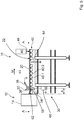
- FIG 3 shows the tread manufacturing device 10 in a schematic view from the side. It can be seen that the tread manufacturing device 10 has a resistance determining device 30, which has an outer electrode 32 and an inner electrode 34.
- the outer electrode 32 comprises a wheel 36 which is attached to an arm 38 in an electrically conductive manner.
- the inner electrode 34 is formed by at least one support roller 40.1 of a conveyor device 42.
- the conveyor device 42 transports the tread 20 from the head 14 (cf. Figure 1 ) path.
- An evaluation circuit 44 determines the electrical resistance W 28 between the outer electrode 32 and the inner electrode 34, which is a very good approximation of the resistance of the conductive strip 28 (cf. Fig. 2 ) corresponds.
- the electrodes 32, 34 are arranged closely behind the head 14 with respect to a material flow direction M. If the evaluation circuit 44 determines an electrical resistance W 28 which is greater than a predetermined maximum resistance W 28, max , it outputs a warning signal.
- the warning signal can, for example, be an electrical signal to a control unit which also controls the extruder system 12. Alternatively, it is an acoustic and / or optical signal so that a machine operator can recognize the error.
- the evaluation posture 44 is connected wirelessly or wired to a schematically drawn marking device 46, which in this case applies paint 48 to the tread 20, in particular sprays it on. This will mark the portion of the tread that may not be used to make tires.
- Figure 4 shows a schematic side view of a tread manufacturing device 10 according to a second embodiment of the invention. It can be seen that both the outer electrode 32 and the inner electrode 34 have a multiplicity of hair-like conductors 50.1, 50.2,... Which are combined in a block 50 and are thus electrically contacted.
- a cutting system 54 and a vulcanizing device 56, which are used to produce tires using the tread 20, are shown in a purely schematic manner.
- Figure 5 shows a further tread manufacturing device 10 according to the invention, in which an electrode, in the present case the outer electrode 32, is arranged for grounding the tread 20 and in particular the conductive strip 28.
- an electrode in the present case the outer electrode 32
- the orientation of the tread 20 may not be the other way around throughout the description. In other words, there is no change in the structure of the tread manufacturing device if the tread does not rest on the conveyor device 42 with its outside 22 facing up, but with the outside 22 facing down.
- the outer electrode 32 could therefore also be called the first electrode, which could be the inner electrode 34 also called the second electrode.
- the terms external electrode and internal electrode are only used for the sake of simplicity.
- the tread manufacturing device 10 has an inner electrode 34 which is designed for contactless contacting of the tread 20.
- the inner electrode 34 has an emission edge 58 and is connected to a high voltage source 60.
- the guide strip 28 (cf. Fig. 2 ) correctly designed, its electrical resistance W 28 is smaller than the specified maximum resistance W 28, max .
- an electrical current I is established between the inner electrode 34 and the outer electrode 32.
- the outer electrode 32 is earthed and the high-voltage source 60 generates a voltage also with respect to earth.
- the outer electrode it is possible for the outer electrode to be connected directly to the high-voltage source 60.
- the electrical current I is detected by the evaluation circuit which is connected to the high-voltage source 60. It is also possible for the high-voltage source 60 to be part of the evaluation circuit 44. The greater the electrical current E, the lower the electrical resistance W 28 of the conductive strip 28.
- the conductive strip 28 is defective, that is to say that it has too high an electrical resistance, then the electrons 62 permanently accumulate on the tread 20. There it forms a permanent electrical charge Q. This charge Q leads to an electrical field which is superimposed on the electrical field of the inner electrode and causes the current I to decrease.
- a discharge electrode 64 by means of which the tread 20 is largely discharged, is arranged behind the electrodes 32, 34 in the material flow direction M. It is possible and preferred that the discharge electrode works without contact, as in the present case. However, it is also possible for the discharge electrode 64 to operate in a contacting manner.
- Figure 6 shows a further alternative embodiment of a tread manufacturing device 10 according to the invention, in which the outer electrode is designed as a contactless electrode. This applies the electrical charge Q to the outside 22 of the tread 20.
- the tread is grounded by means of the inner electrode 34, which in the present case has a wheel 36, as described above, which the conductive strip 28 (cf. Fig. 2 ) touched.
- FIG. 11 shows a schematic view from above of the outer electrode 32. It can be seen that the emission edge 58 extends transversely to a longitudinal direction L of the tread 20.
- an offset angle ⁇ in the present case is preferably at least 75 ° at most and 105 ° at most.
- the electrode is fixed by means of a rotating device 66 (cf. Fig. 6 ) rotatable so that the offset angle a can be adjusted. In this way, the offset angle ⁇ and thus an effective width B eff of the outer electrode 32 can be varied. It is favorable if the effective width B eff is greater than the width b of the guide strip 28. However, it is also favorable if the effective width B eff is at least three times, preferably at least five times, the width b of the guide strip 28. It is favorable as a rule, if the effective width B eff is at most 50 times, in particular 30 times, the width b of the guide strip.
- the evaluation circuit 44 continuously compares whether the parameter P, in the present case the electrical current I, has a value which indicates that the conductive strip resistance W 28 does not exceed the predetermined maximum value W 28, max. If the parameter P is the electrical charging current I, then falling below a minimum current I min means that the conductive strip resistance W 28 exceeds the predetermined maximum value W 28, max. For example, the electrical current I is determined at least once per second, preferably at least once every tenth of a second.
- the charge Q can - as described above - be applied in the form of electrons.
- the respective electrode it is also possible for the respective electrode to be designed as an ion spray rod, which accelerates ions onto the tread 20 and thus charges it electrostatically.
Landscapes
- Engineering & Computer Science (AREA)
- Mechanical Engineering (AREA)
- Chemical & Material Sciences (AREA)
- Analytical Chemistry (AREA)
- General Health & Medical Sciences (AREA)
- Physics & Mathematics (AREA)
- Health & Medical Sciences (AREA)
- Life Sciences & Earth Sciences (AREA)
- Chemical Kinetics & Catalysis (AREA)
- Biochemistry (AREA)
- Electrochemistry (AREA)
- General Physics & Mathematics (AREA)
- Immunology (AREA)
- Pathology (AREA)
- Tyre Moulding (AREA)
- Extrusion Moulding Of Plastics Or The Like (AREA)
- Tires In General (AREA)
Priority Applications (1)
| Application Number | Priority Date | Filing Date | Title |
|---|---|---|---|
| PL17800474T PL3548254T3 (pl) | 2016-12-02 | 2017-11-08 | Sposób wytwarzania bieżnika i urządzenie do wytwarzania bieżnika |
Applications Claiming Priority (3)
| Application Number | Priority Date | Filing Date | Title |
|---|---|---|---|
| DE102016123339 | 2016-12-02 | ||
| DE102017108943.8A DE102017108943A1 (de) | 2016-12-02 | 2017-04-26 | Verfahren zum Herstellen eines Laufstreifens und Laufstreifen-Herstellvorrichtung |
| PCT/EP2017/078639 WO2018099704A1 (de) | 2016-12-02 | 2017-11-08 | Verfahren zum herstellen eines laufstreifens und laufstreifen-herstellvorrichtung |
Publications (2)
| Publication Number | Publication Date |
|---|---|
| EP3548254A1 EP3548254A1 (de) | 2019-10-09 |
| EP3548254B1 true EP3548254B1 (de) | 2021-04-28 |
Family
ID=62164244
Family Applications (1)
| Application Number | Title | Priority Date | Filing Date |
|---|---|---|---|
| EP17800474.3A Active EP3548254B1 (de) | 2016-12-02 | 2017-11-08 | Verfahren zum herstellen eines laufstreifens und laufstreifen-herstellvorrichtung |
Country Status (11)
| Country | Link |
|---|---|
| US (1) | US11292218B2 (pl) |
| EP (1) | EP3548254B1 (pl) |
| KR (1) | KR102352731B1 (pl) |
| CN (1) | CN109982823B (pl) |
| BR (1) | BR112019006849B1 (pl) |
| DE (1) | DE102017108943A1 (pl) |
| ES (1) | ES2877816T3 (pl) |
| MX (1) | MX2019005926A (pl) |
| PL (1) | PL3548254T3 (pl) |
| RU (1) | RU2747529C2 (pl) |
| WO (1) | WO2018099704A1 (pl) |
Families Citing this family (4)
| Publication number | Priority date | Publication date | Assignee | Title |
|---|---|---|---|---|
| DE102017108943A1 (de) * | 2016-12-02 | 2018-06-07 | Kraussmaffei Berstorff Gmbh | Verfahren zum Herstellen eines Laufstreifens und Laufstreifen-Herstellvorrichtung |
| CN113366295B (zh) * | 2018-12-13 | 2024-06-18 | 倍耐力轮胎股份公司 | 用于检查车辆车轮用轮胎的电导率的方法和装置 |
| CN113433170A (zh) * | 2021-06-29 | 2021-09-24 | 福达合金材料股份有限公司 | 一种电触点材料物理性能动态检测方法 |
| US11874223B1 (en) * | 2022-08-30 | 2024-01-16 | The Goodyear Tire & Rubber Company | Terahertz characterization of a multi-layered tire tread |
Family Cites Families (34)
| Publication number | Priority date | Publication date | Assignee | Title |
|---|---|---|---|---|
| US3710241A (en) * | 1970-09-08 | 1973-01-09 | Dineen Enterprises Inc | Apparatus for detecting faults in extruded insulating or dielectric material |
| BE792549A (fr) * | 1971-12-13 | 1973-03-30 | Zumbach Electronic Automatic | Procede de controle de l'epaisseur d'une paroi de tube en matiere isolante et dispositif pour la mise en oeuvre de ce procede |
| DE2517709C3 (de) * | 1975-04-22 | 1979-07-12 | Harald 2800 Bremen Sikora | Vorrichtung zur Messung und Regelung der Wanddicke von isolierten Strängen |
| DE2521278C3 (de) * | 1975-05-13 | 1978-09-21 | Maschinenbau Scholz Gmbh & Co Kg, 4420 Coesfeld | Vorrichtung zur Messung des Durchhanges eines mit einer Isolierschicht ummantelten Leiters in einem Vulkanisierrohr |
| US4260566A (en) * | 1979-10-24 | 1981-04-07 | Aluminum Company Of America | Strand shield defect detector |
| SU1089389A1 (ru) * | 1980-05-14 | 1984-04-30 | Всесоюзный Научно-Исследовательский И Проектно-Конструкторский Институт Нефтяного Машиностроения | Устройство дл контрол размеров беговых дорожек наружных колец шариковых подшипников |
| US4592881A (en) * | 1982-11-15 | 1986-06-03 | Beta Instrument Company Limited | Method for controlling a foam resin cable coating extrusion process |
| ES2259198T3 (es) * | 1997-08-07 | 2006-09-16 | Bridgestone Corporation | Cubierta neumatica y metodo de fabricacion de la misma. |
| JPH11151907A (ja) * | 1997-08-07 | 1999-06-08 | Bridgestone Corp | 空気入りタイヤおよびその製造方法 |
| CN1159171C (zh) * | 1998-02-26 | 2004-07-28 | 米什兰集团总公司 | 导电轮胎和挤压导电成型部件的方法 |
| JP2000230949A (ja) * | 1999-02-09 | 2000-08-22 | Toyobo Co Ltd | 表面抵抗測定装置 |
| IT1310690B1 (it) * | 1999-09-07 | 2002-02-22 | Bridgestone Firestone Tech | Metodo e dispositivo per il controllo in linea di componenti crudiutilizzati per la produzione di pneumatici |
| ES2238242T3 (es) * | 1999-11-23 | 2005-09-01 | Societe De Technologie Michelin | Aparato para la coextrusion de mezclas de caucho. |
| KR20010095423A (ko) * | 2000-03-30 | 2001-11-07 | 신형인 | 정전기 방출이 원활한 실리카 적용 타이어구조 |
| JP4610062B2 (ja) * | 2000-09-14 | 2011-01-12 | 株式会社ブリヂストン | バフ方法 |
| JP4510557B2 (ja) * | 2004-09-01 | 2010-07-28 | 住友ゴム工業株式会社 | ゴムストリップ巻付体の形成装置 |
| JP4255435B2 (ja) * | 2004-11-11 | 2009-04-15 | 住友ゴム工業株式会社 | 空気入りタイヤの製造方法 |
| JP2007153092A (ja) * | 2005-12-02 | 2007-06-21 | Sumitomo Rubber Ind Ltd | 空気入りタイヤおよび該空気入りタイヤの製造方法 |
| CN101374680B (zh) * | 2006-02-20 | 2010-07-07 | 东洋橡胶工业株式会社 | 充气轮胎以及充气轮胎的制造方法 |
| JP5065762B2 (ja) * | 2007-05-18 | 2012-11-07 | 住友ゴム工業株式会社 | 空気入りタイヤ |
| JP4382119B2 (ja) * | 2007-08-10 | 2009-12-09 | 東洋ゴム工業株式会社 | 空気入りタイヤの製造方法及び空気入りタイヤ |
| EP2036704B1 (en) * | 2007-09-11 | 2013-09-18 | Artic Investments S.A. | Method of manufacturing a non-marking antistatic tire and tire obtaind thereby. |
| JP4947556B2 (ja) * | 2007-11-26 | 2012-06-06 | 東洋ゴム工業株式会社 | 空気入りタイヤの製造方法及び空気入りタイヤ |
| JP5510629B2 (ja) | 2009-02-20 | 2014-06-04 | 国立大学法人山形大学 | 電荷移動速度測定装置及び方法、表面抵抗測定装置及び方法、並びに、それらのためのプログラム |
| JP5155935B2 (ja) * | 2009-05-18 | 2013-03-06 | 住友ゴム工業株式会社 | 空気入りタイヤ及びその製造方法 |
| FR2968592B1 (fr) * | 2010-12-13 | 2013-01-11 | Michelin Soc Tech | Procede de fabrication d'une ebauche de pneumatique au moyen d'une nappe comprenant deux gommes |
| JP5675403B2 (ja) * | 2011-02-08 | 2015-02-25 | 株式会社ブリヂストン | タイヤの製造方法 |
| NL2007544C2 (en) * | 2011-10-06 | 2012-09-25 | Apollo Vredestein Bv | Antistatic vehicle tire and method of manufacturing such a tire. |
| JP5943810B2 (ja) | 2012-10-31 | 2016-07-05 | 三菱重工マシナリーテクノロジー株式会社 | タイヤの電気抵抗測定装置 |
| JP6759703B2 (ja) * | 2016-05-19 | 2020-09-23 | 住友ゴム工業株式会社 | 空気入りタイヤ及びその製造方法 |
| DE102017108943A1 (de) * | 2016-12-02 | 2018-06-07 | Kraussmaffei Berstorff Gmbh | Verfahren zum Herstellen eines Laufstreifens und Laufstreifen-Herstellvorrichtung |
| JP6897189B2 (ja) * | 2017-03-16 | 2021-06-30 | 住友ゴム工業株式会社 | 空気入りタイヤ及びその製造方法 |
| US11826928B2 (en) * | 2017-12-08 | 2023-11-28 | The Yokohama Rubber Co., Ltd. | Quality inspection method and quality inspection system for unvulcanized rubber material, and production method and production system for unvulcanized rubber material |
| WO2019123322A1 (en) * | 2017-12-20 | 2019-06-27 | Pirelli Tyre S.P.A. | Process and apparatus for building tyres for vehicle wheels |
-
2017
- 2017-04-26 DE DE102017108943.8A patent/DE102017108943A1/de not_active Withdrawn
- 2017-11-08 PL PL17800474T patent/PL3548254T3/pl unknown
- 2017-11-08 CN CN201780072803.XA patent/CN109982823B/zh active Active
- 2017-11-08 US US16/346,759 patent/US11292218B2/en active Active
- 2017-11-08 ES ES17800474T patent/ES2877816T3/es active Active
- 2017-11-08 BR BR112019006849-0A patent/BR112019006849B1/pt active IP Right Grant
- 2017-11-08 WO PCT/EP2017/078639 patent/WO2018099704A1/de not_active Ceased
- 2017-11-08 EP EP17800474.3A patent/EP3548254B1/de active Active
- 2017-11-08 MX MX2019005926A patent/MX2019005926A/es unknown
- 2017-11-08 KR KR1020197014160A patent/KR102352731B1/ko active Active
- 2017-11-08 RU RU2019111680A patent/RU2747529C2/ru active
Non-Patent Citations (1)
| Title |
|---|
| None * |
Also Published As
| Publication number | Publication date |
|---|---|
| MX2019005926A (es) | 2019-07-08 |
| RU2019111680A3 (pl) | 2021-01-11 |
| WO2018099704A1 (de) | 2018-06-07 |
| ES2877816T3 (es) | 2021-11-17 |
| CN109982823A (zh) | 2019-07-05 |
| RU2019111680A (ru) | 2021-01-11 |
| KR102352731B1 (ko) | 2022-01-17 |
| RU2747529C2 (ru) | 2021-05-06 |
| DE102017108943A1 (de) | 2018-06-07 |
| US20190275723A1 (en) | 2019-09-12 |
| KR20190086676A (ko) | 2019-07-23 |
| BR112019006849A8 (pt) | 2022-09-13 |
| BR112019006849B1 (pt) | 2022-12-06 |
| US11292218B2 (en) | 2022-04-05 |
| EP3548254A1 (de) | 2019-10-09 |
| CN109982823B (zh) | 2022-05-24 |
| PL3548254T3 (pl) | 2021-10-25 |
| BR112019006849A2 (pt) | 2019-06-25 |
Similar Documents
| Publication | Publication Date | Title |
|---|---|---|
| EP3548254B1 (de) | Verfahren zum herstellen eines laufstreifens und laufstreifen-herstellvorrichtung | |
| DE102007039100A1 (de) | Verfahren zur Herstellung eines Fahrzeugluftreifens und Fahrzeugluftreifen | |
| EP2125351A1 (de) | Verfahren zur herstellung eines fahrzeugluftreifens und fahrzeugluftreifen | |
| WO2015003825A1 (de) | Fahrzeugluftreifen | |
| DE112006003758B4 (de) | Verfahren zum Herstellen eines Luftreifens und Luftreifen | |
| EP3599113B1 (de) | Reifen sowie verfahren zum herstellen eines reifens | |
| EP3012095B1 (de) | Verfahren zur herstellung eines fahrzeugluftreifens und fahrzeugluftreifen | |
| EP1857262B1 (de) | Verfahren zum Herstellen eines Fahrzeugluftreifens | |
| DE19644538C1 (de) | Fahrzeugluftreifen | |
| WO2011015608A2 (de) | Vorrichtung und verfahren zur oberflächenbearbeitung mit einer prüfstation | |
| EP2939855B1 (de) | Fahrzeugluftreifen aufweisend einen Streifen aus einer elektrisch leitfähigen Gummimischung | |
| DE10032857A1 (de) | Verfahren zur Herstellung von Luftreifen mit verbesserter elektrischer Leitfähigkeit | |
| EP1878593B1 (de) | Verfahren zur Herstellung eines Fahrzeugluftreifens | |
| EP0816057B1 (de) | Herstellung eines Fahrzeugluftreifens mit Lauffläche | |
| EP1878592B1 (de) | Verfahren zur Herstellung eines Fahrzeugluftreifens | |
| EP3085553A1 (de) | Verfahren zur herstellung von elektrisch leitfähigen passagen in einer seitenwand eines fahrzeugluftreifens und damit hergestellter fahrzeugluftreifen | |
| DE112020003671B4 (de) | Luftreifen und Verfahren zur Herstellung von Reifenrohlingen | |
| EP3760424B1 (de) | Verfahren zum herstellen eines fahrzeugluftreifens, verwendung von strip-winding zum aufwickeln einer oder mehrerer kautschukkomponenten, vorrichtung zur durchführung des verfahrens und einen fahrzeugluftreifen herstellbar oder hergestellt gemäss dem verfahren | |
| DE102018200604A1 (de) | Aufprallsensor mit zumindest zwei voneinander beabstandeten Elektroden sowie Verfahren zur Aufprallerkennung sowie Auslösung von Schutzeinrichtungen mit einem solchen Aufprallsensor | |
| EP4570485A1 (de) | Laufstreifen und verfahren zum ausbilden eines laufstreifens zum herstellen eines reifens für ein kraftfahrzeug | |
| DE102023212678A1 (de) | Verfahren zur Messung des elektrischen Widerstandes eines Extrudates und Vorrichtung für das Verfahren | |
| DE102011112519A1 (de) | Vorrichtung zum Aufbringen eines Mediums auf ein Objekt und Verfahren zur Detektion von Abweichungen eines Sprühfeldes | |
| EP3736143A1 (de) | Reifen mit einer vorrichtung umfassend eine elektrodenschicht und eine kautschukschicht sowie die verwendung des reifens und der vorrichtung in einem reifen | |
| DE102020209457A1 (de) | Fahrzeugluftreifen aufweisend einen elektrisch leitfähigen Pfad | |
| DE102008041627A1 (de) | Verfahren und Vorrichtung zur Ermittlung von Feuchtigkeit |
Legal Events
| Date | Code | Title | Description |
|---|---|---|---|
| STAA | Information on the status of an ep patent application or granted ep patent |
Free format text: STATUS: UNKNOWN |
|
| STAA | Information on the status of an ep patent application or granted ep patent |
Free format text: STATUS: THE INTERNATIONAL PUBLICATION HAS BEEN MADE |
|
| PUAI | Public reference made under article 153(3) epc to a published international application that has entered the european phase |
Free format text: ORIGINAL CODE: 0009012 |
|
| STAA | Information on the status of an ep patent application or granted ep patent |
Free format text: STATUS: REQUEST FOR EXAMINATION WAS MADE |
|
| 17P | Request for examination filed |
Effective date: 20190702 |
|
| AK | Designated contracting states |
Kind code of ref document: A1 Designated state(s): AL AT BE BG CH CY CZ DE DK EE ES FI FR GB GR HR HU IE IS IT LI LT LU LV MC MK MT NL NO PL PT RO RS SE SI SK SM TR |
|
| AX | Request for extension of the european patent |
Extension state: BA ME |
|
| DAV | Request for validation of the european patent (deleted) | ||
| DAX | Request for extension of the european patent (deleted) | ||
| RAP1 | Party data changed (applicant data changed or rights of an application transferred) |
Owner name: KRAUSSMAFFEI EXTRUSION GMBH |
|
| STAA | Information on the status of an ep patent application or granted ep patent |
Free format text: STATUS: EXAMINATION IS IN PROGRESS |
|
| 17Q | First examination report despatched |
Effective date: 20200623 |
|
| REG | Reference to a national code |
Ref country code: DE Ref legal event code: R079 Ref document number: 502017010235 Country of ref document: DE Free format text: PREVIOUS MAIN CLASS: B29C0047920000 Ipc: B29C0048920000 |
|
| GRAP | Despatch of communication of intention to grant a patent |
Free format text: ORIGINAL CODE: EPIDOSNIGR1 |
|
| STAA | Information on the status of an ep patent application or granted ep patent |
Free format text: STATUS: GRANT OF PATENT IS INTENDED |
|
| RIC1 | Information provided on ipc code assigned before grant |
Ipc: B29C 48/92 20190101AFI20201109BHEP Ipc: B60C 19/08 20060101ALI20201109BHEP Ipc: B29D 30/52 20060101ALI20201109BHEP Ipc: G01N 27/04 20060101ALI20201109BHEP Ipc: B29C 48/49 20190101ALI20201109BHEP Ipc: B29C 48/21 20190101ALI20201109BHEP Ipc: B29K 105/00 20060101ALN20201109BHEP |
|
| INTG | Intention to grant announced |
Effective date: 20201204 |
|
| GRAS | Grant fee paid |
Free format text: ORIGINAL CODE: EPIDOSNIGR3 |
|
| GRAA | (expected) grant |
Free format text: ORIGINAL CODE: 0009210 |
|
| STAA | Information on the status of an ep patent application or granted ep patent |
Free format text: STATUS: THE PATENT HAS BEEN GRANTED |
|
| AK | Designated contracting states |
Kind code of ref document: B1 Designated state(s): AL AT BE BG CH CY CZ DE DK EE ES FI FR GB GR HR HU IE IS IT LI LT LU LV MC MK MT NL NO PL PT RO RS SE SI SK SM TR |
|
| REG | Reference to a national code |
Ref country code: GB Ref legal event code: FG4D Free format text: NOT ENGLISH |
|
| REG | Reference to a national code |
Ref country code: CH Ref legal event code: EP |
|
| REG | Reference to a national code |
Ref country code: DE Ref legal event code: R096 Ref document number: 502017010235 Country of ref document: DE |
|
| REG | Reference to a national code |
Ref country code: AT Ref legal event code: REF Ref document number: 1386612 Country of ref document: AT Kind code of ref document: T Effective date: 20210515 |
|
| REG | Reference to a national code |
Ref country code: IE Ref legal event code: FG4D Free format text: LANGUAGE OF EP DOCUMENT: GERMAN |
|
| REG | Reference to a national code |
Ref country code: NL Ref legal event code: FP |
|
| REG | Reference to a national code |
Ref country code: RO Ref legal event code: EPE |
|
| REG | Reference to a national code |
Ref country code: LT Ref legal event code: MG9D |
|
| REG | Reference to a national code |
Ref country code: SK Ref legal event code: T3 Ref document number: E 37682 Country of ref document: SK |
|
| PG25 | Lapsed in a contracting state [announced via postgrant information from national office to epo] |
Ref country code: LT Free format text: LAPSE BECAUSE OF FAILURE TO SUBMIT A TRANSLATION OF THE DESCRIPTION OR TO PAY THE FEE WITHIN THE PRESCRIBED TIME-LIMIT Effective date: 20210428 Ref country code: FI Free format text: LAPSE BECAUSE OF FAILURE TO SUBMIT A TRANSLATION OF THE DESCRIPTION OR TO PAY THE FEE WITHIN THE PRESCRIBED TIME-LIMIT Effective date: 20210428 Ref country code: BG Free format text: LAPSE BECAUSE OF FAILURE TO SUBMIT A TRANSLATION OF THE DESCRIPTION OR TO PAY THE FEE WITHIN THE PRESCRIBED TIME-LIMIT Effective date: 20210728 Ref country code: HR Free format text: LAPSE BECAUSE OF FAILURE TO SUBMIT A TRANSLATION OF THE DESCRIPTION OR TO PAY THE FEE WITHIN THE PRESCRIBED TIME-LIMIT Effective date: 20210428 |
|
| REG | Reference to a national code |
Ref country code: ES Ref legal event code: FG2A Ref document number: 2877816 Country of ref document: ES Kind code of ref document: T3 Effective date: 20211117 |
|
| PG25 | Lapsed in a contracting state [announced via postgrant information from national office to epo] |
Ref country code: SE Free format text: LAPSE BECAUSE OF FAILURE TO SUBMIT A TRANSLATION OF THE DESCRIPTION OR TO PAY THE FEE WITHIN THE PRESCRIBED TIME-LIMIT Effective date: 20210428 Ref country code: RS Free format text: LAPSE BECAUSE OF FAILURE TO SUBMIT A TRANSLATION OF THE DESCRIPTION OR TO PAY THE FEE WITHIN THE PRESCRIBED TIME-LIMIT Effective date: 20210428 Ref country code: PT Free format text: LAPSE BECAUSE OF FAILURE TO SUBMIT A TRANSLATION OF THE DESCRIPTION OR TO PAY THE FEE WITHIN THE PRESCRIBED TIME-LIMIT Effective date: 20210830 Ref country code: LV Free format text: LAPSE BECAUSE OF FAILURE TO SUBMIT A TRANSLATION OF THE DESCRIPTION OR TO PAY THE FEE WITHIN THE PRESCRIBED TIME-LIMIT Effective date: 20210428 Ref country code: NO Free format text: LAPSE BECAUSE OF FAILURE TO SUBMIT A TRANSLATION OF THE DESCRIPTION OR TO PAY THE FEE WITHIN THE PRESCRIBED TIME-LIMIT Effective date: 20210728 Ref country code: GR Free format text: LAPSE BECAUSE OF FAILURE TO SUBMIT A TRANSLATION OF THE DESCRIPTION OR TO PAY THE FEE WITHIN THE PRESCRIBED TIME-LIMIT Effective date: 20210729 Ref country code: IS Free format text: LAPSE BECAUSE OF FAILURE TO SUBMIT A TRANSLATION OF THE DESCRIPTION OR TO PAY THE FEE WITHIN THE PRESCRIBED TIME-LIMIT Effective date: 20210828 |
|
| PG25 | Lapsed in a contracting state [announced via postgrant information from national office to epo] |
Ref country code: SM Free format text: LAPSE BECAUSE OF FAILURE TO SUBMIT A TRANSLATION OF THE DESCRIPTION OR TO PAY THE FEE WITHIN THE PRESCRIBED TIME-LIMIT Effective date: 20210428 Ref country code: DK Free format text: LAPSE BECAUSE OF FAILURE TO SUBMIT A TRANSLATION OF THE DESCRIPTION OR TO PAY THE FEE WITHIN THE PRESCRIBED TIME-LIMIT Effective date: 20210428 Ref country code: EE Free format text: LAPSE BECAUSE OF FAILURE TO SUBMIT A TRANSLATION OF THE DESCRIPTION OR TO PAY THE FEE WITHIN THE PRESCRIBED TIME-LIMIT Effective date: 20210428 |
|
| REG | Reference to a national code |
Ref country code: DE Ref legal event code: R097 Ref document number: 502017010235 Country of ref document: DE |
|
| PLBE | No opposition filed within time limit |
Free format text: ORIGINAL CODE: 0009261 |
|
| STAA | Information on the status of an ep patent application or granted ep patent |
Free format text: STATUS: NO OPPOSITION FILED WITHIN TIME LIMIT |
|
| 26N | No opposition filed |
Effective date: 20220131 |
|
| PG25 | Lapsed in a contracting state [announced via postgrant information from national office to epo] |
Ref country code: IS Free format text: LAPSE BECAUSE OF FAILURE TO SUBMIT A TRANSLATION OF THE DESCRIPTION OR TO PAY THE FEE WITHIN THE PRESCRIBED TIME-LIMIT Effective date: 20210828 Ref country code: AL Free format text: LAPSE BECAUSE OF FAILURE TO SUBMIT A TRANSLATION OF THE DESCRIPTION OR TO PAY THE FEE WITHIN THE PRESCRIBED TIME-LIMIT Effective date: 20210428 |
|
| PG25 | Lapsed in a contracting state [announced via postgrant information from national office to epo] |
Ref country code: MC Free format text: LAPSE BECAUSE OF FAILURE TO SUBMIT A TRANSLATION OF THE DESCRIPTION OR TO PAY THE FEE WITHIN THE PRESCRIBED TIME-LIMIT Effective date: 20210428 |
|
| REG | Reference to a national code |
Ref country code: CH Ref legal event code: PL |
|
| GBPC | Gb: european patent ceased through non-payment of renewal fee |
Effective date: 20211108 |
|
| PG25 | Lapsed in a contracting state [announced via postgrant information from national office to epo] |
Ref country code: LU Free format text: LAPSE BECAUSE OF NON-PAYMENT OF DUE FEES Effective date: 20211108 Ref country code: BE Free format text: LAPSE BECAUSE OF NON-PAYMENT OF DUE FEES Effective date: 20211130 |
|
| REG | Reference to a national code |
Ref country code: BE Ref legal event code: MM Effective date: 20211130 |
|
| PG25 | Lapsed in a contracting state [announced via postgrant information from national office to epo] |
Ref country code: IE Free format text: LAPSE BECAUSE OF NON-PAYMENT OF DUE FEES Effective date: 20211108 Ref country code: GB Free format text: LAPSE BECAUSE OF NON-PAYMENT OF DUE FEES Effective date: 20211108 |
|
| PG25 | Lapsed in a contracting state [announced via postgrant information from national office to epo] |
Ref country code: CY Free format text: LAPSE BECAUSE OF FAILURE TO SUBMIT A TRANSLATION OF THE DESCRIPTION OR TO PAY THE FEE WITHIN THE PRESCRIBED TIME-LIMIT Effective date: 20210428 |
|
| PG25 | Lapsed in a contracting state [announced via postgrant information from national office to epo] |
Ref country code: LI Free format text: LAPSE BECAUSE OF NON-PAYMENT OF DUE FEES Effective date: 20220630 Ref country code: HU Free format text: LAPSE BECAUSE OF FAILURE TO SUBMIT A TRANSLATION OF THE DESCRIPTION OR TO PAY THE FEE WITHIN THE PRESCRIBED TIME-LIMIT; INVALID AB INITIO Effective date: 20171108 Ref country code: CH Free format text: LAPSE BECAUSE OF NON-PAYMENT OF DUE FEES Effective date: 20220630 |
|
| REG | Reference to a national code |
Ref country code: AT Ref legal event code: MM01 Ref document number: 1386612 Country of ref document: AT Kind code of ref document: T Effective date: 20221108 |
|
| PG25 | Lapsed in a contracting state [announced via postgrant information from national office to epo] |
Ref country code: AT Free format text: LAPSE BECAUSE OF NON-PAYMENT OF DUE FEES Effective date: 20221108 |
|
| PGFP | Annual fee paid to national office [announced via postgrant information from national office to epo] |
Ref country code: ES Payment date: 20240130 Year of fee payment: 7 |
|
| PG25 | Lapsed in a contracting state [announced via postgrant information from national office to epo] |
Ref country code: MK Free format text: LAPSE BECAUSE OF FAILURE TO SUBMIT A TRANSLATION OF THE DESCRIPTION OR TO PAY THE FEE WITHIN THE PRESCRIBED TIME-LIMIT Effective date: 20210428 |
|
| PG25 | Lapsed in a contracting state [announced via postgrant information from national office to epo] |
Ref country code: MT Free format text: LAPSE BECAUSE OF FAILURE TO SUBMIT A TRANSLATION OF THE DESCRIPTION OR TO PAY THE FEE WITHIN THE PRESCRIBED TIME-LIMIT Effective date: 20210428 |
|
| PGFP | Annual fee paid to national office [announced via postgrant information from national office to epo] |
Ref country code: NL Payment date: 20241120 Year of fee payment: 8 |
|
| PGFP | Annual fee paid to national office [announced via postgrant information from national office to epo] |
Ref country code: PL Payment date: 20241104 Year of fee payment: 8 |
|
| PGFP | Annual fee paid to national office [announced via postgrant information from national office to epo] |
Ref country code: FR Payment date: 20241128 Year of fee payment: 8 |
|
| PGFP | Annual fee paid to national office [announced via postgrant information from national office to epo] |
Ref country code: RO Payment date: 20241101 Year of fee payment: 8 |
|
| PGFP | Annual fee paid to national office [announced via postgrant information from national office to epo] |
Ref country code: IT Payment date: 20241126 Year of fee payment: 8 |
|
| PGFP | Annual fee paid to national office [announced via postgrant information from national office to epo] |
Ref country code: TR Payment date: 20241101 Year of fee payment: 8 |
|
| REG | Reference to a national code |
Ref country code: ES Ref legal event code: FD2A Effective date: 20260102 |
|
| PGFP | Annual fee paid to national office [announced via postgrant information from national office to epo] |
Ref country code: DE Payment date: 20251119 Year of fee payment: 9 |
|
| PGFP | Annual fee paid to national office [announced via postgrant information from national office to epo] |
Ref country code: CZ Payment date: 20251105 Year of fee payment: 9 |
|
| PGFP | Annual fee paid to national office [announced via postgrant information from national office to epo] |
Ref country code: SK Payment date: 20251104 Year of fee payment: 9 |
|
| PG25 | Lapsed in a contracting state [announced via postgrant information from national office to epo] |
Ref country code: ES Free format text: LAPSE BECAUSE OF NON-PAYMENT OF DUE FEES Effective date: 20241109 |