EP3547307A1 - Vliesstoff für ein schallabsorbierendes material und schallabsorbierendes material damit - Google Patents
Vliesstoff für ein schallabsorbierendes material und schallabsorbierendes material damit Download PDFInfo
- Publication number
- EP3547307A1 EP3547307A1 EP17874030.4A EP17874030A EP3547307A1 EP 3547307 A1 EP3547307 A1 EP 3547307A1 EP 17874030 A EP17874030 A EP 17874030A EP 3547307 A1 EP3547307 A1 EP 3547307A1
- Authority
- EP
- European Patent Office
- Prior art keywords
- nonwoven fabric
- filaments
- sound absorbing
- absorbing material
- oriented
- Prior art date
- Legal status (The legal status is an assumption and is not a legal conclusion. Google has not performed a legal analysis and makes no representation as to the accuracy of the status listed.)
- Granted
Links
- 239000004745 nonwoven fabric Substances 0.000 title claims abstract description 196
- 239000011358 absorbing material Substances 0.000 title claims abstract description 59
- 238000009826 distribution Methods 0.000 claims abstract description 23
- 229920000139 polyethylene terephthalate Polymers 0.000 claims description 28
- 239000005020 polyethylene terephthalate Substances 0.000 claims description 28
- -1 polypropylene Polymers 0.000 claims description 8
- 229920000728 polyester Polymers 0.000 claims description 6
- 239000004743 Polypropylene Substances 0.000 claims description 4
- 229920001155 polypropylene Polymers 0.000 claims description 4
- 230000035699 permeability Effects 0.000 claims description 3
- 238000010521 absorption reaction Methods 0.000 abstract description 19
- 238000009987 spinning Methods 0.000 description 58
- 230000007246 mechanism Effects 0.000 description 47
- 238000004519 manufacturing process Methods 0.000 description 37
- 229920005992 thermoplastic resin Polymers 0.000 description 17
- 230000000052 comparative effect Effects 0.000 description 9
- 230000000694 effects Effects 0.000 description 9
- 239000007921 spray Substances 0.000 description 9
- 238000001816 cooling Methods 0.000 description 6
- 239000000835 fiber Substances 0.000 description 6
- 239000000463 material Substances 0.000 description 6
- 238000005259 measurement Methods 0.000 description 6
- 238000000034 method Methods 0.000 description 6
- 238000002844 melting Methods 0.000 description 5
- 230000008018 melting Effects 0.000 description 5
- 239000003595 mist Substances 0.000 description 5
- 229920005989 resin Polymers 0.000 description 5
- 239000011347 resin Substances 0.000 description 5
- XLYOFNOQVPJJNP-UHFFFAOYSA-N water Substances O XLYOFNOQVPJJNP-UHFFFAOYSA-N 0.000 description 5
- 230000008859 change Effects 0.000 description 4
- 238000003475 lamination Methods 0.000 description 4
- RNFJDJUURJAICM-UHFFFAOYSA-N 2,2,4,4,6,6-hexaphenoxy-1,3,5-triaza-2$l^{5},4$l^{5},6$l^{5}-triphosphacyclohexa-1,3,5-triene Chemical compound N=1P(OC=2C=CC=CC=2)(OC=2C=CC=CC=2)=NP(OC=2C=CC=CC=2)(OC=2C=CC=CC=2)=NP=1(OC=1C=CC=CC=1)OC1=CC=CC=C1 RNFJDJUURJAICM-UHFFFAOYSA-N 0.000 description 3
- 238000004049 embossing Methods 0.000 description 3
- 239000003063 flame retardant Substances 0.000 description 3
- 230000008569 process Effects 0.000 description 3
- 238000011144 upstream manufacturing Methods 0.000 description 3
- 229920005830 Polyurethane Foam Polymers 0.000 description 2
- 229920001971 elastomer Polymers 0.000 description 2
- 238000001125 extrusion Methods 0.000 description 2
- 230000005484 gravity Effects 0.000 description 2
- 238000010438 heat treatment Methods 0.000 description 2
- 230000002093 peripheral effect Effects 0.000 description 2
- 230000000704 physical effect Effects 0.000 description 2
- 239000011496 polyurethane foam Substances 0.000 description 2
- 238000012805 post-processing Methods 0.000 description 2
- 230000009467 reduction Effects 0.000 description 2
- OAICVXFJPJFONN-UHFFFAOYSA-N Phosphorus Chemical compound [P] OAICVXFJPJFONN-UHFFFAOYSA-N 0.000 description 1
- 239000000654 additive Substances 0.000 description 1
- 239000003963 antioxidant agent Substances 0.000 description 1
- 230000003078 antioxidant effect Effects 0.000 description 1
- 239000003795 chemical substances by application Substances 0.000 description 1
- 239000003086 colorant Substances 0.000 description 1
- 230000006835 compression Effects 0.000 description 1
- 238000007906 compression Methods 0.000 description 1
- 238000007334 copolymerization reaction Methods 0.000 description 1
- 239000004744 fabric Substances 0.000 description 1
- 230000004927 fusion Effects 0.000 description 1
- 239000011521 glass Substances 0.000 description 1
- 239000011491 glass wool Substances 0.000 description 1
- 238000002347 injection Methods 0.000 description 1
- 239000007924 injection Substances 0.000 description 1
- 238000010030 laminating Methods 0.000 description 1
- 239000007788 liquid Substances 0.000 description 1
- 238000002074 melt spinning Methods 0.000 description 1
- 229910052698 phosphorus Inorganic materials 0.000 description 1
- 239000011574 phosphorus Substances 0.000 description 1
- 230000001681 protective effect Effects 0.000 description 1
- 238000004804 winding Methods 0.000 description 1
- 210000002268 wool Anatomy 0.000 description 1
- 239000002759 woven fabric Substances 0.000 description 1
Images


Classifications
-
- B—PERFORMING OPERATIONS; TRANSPORTING
- B32—LAYERED PRODUCTS
- B32B—LAYERED PRODUCTS, i.e. PRODUCTS BUILT-UP OF STRATA OF FLAT OR NON-FLAT, e.g. CELLULAR OR HONEYCOMB, FORM
- B32B5/00—Layered products characterised by the non- homogeneity or physical structure, i.e. comprising a fibrous, filamentary, particulate or foam layer; Layered products characterised by having a layer differing constitutionally or physically in different parts
- B32B5/02—Layered products characterised by the non- homogeneity or physical structure, i.e. comprising a fibrous, filamentary, particulate or foam layer; Layered products characterised by having a layer differing constitutionally or physically in different parts characterised by structural features of a fibrous or filamentary layer
- B32B5/022—Non-woven fabric
-
- B—PERFORMING OPERATIONS; TRANSPORTING
- B32—LAYERED PRODUCTS
- B32B—LAYERED PRODUCTS, i.e. PRODUCTS BUILT-UP OF STRATA OF FLAT OR NON-FLAT, e.g. CELLULAR OR HONEYCOMB, FORM
- B32B5/00—Layered products characterised by the non- homogeneity or physical structure, i.e. comprising a fibrous, filamentary, particulate or foam layer; Layered products characterised by having a layer differing constitutionally or physically in different parts
- B32B5/18—Layered products characterised by the non- homogeneity or physical structure, i.e. comprising a fibrous, filamentary, particulate or foam layer; Layered products characterised by having a layer differing constitutionally or physically in different parts characterised by features of a layer of foamed material
-
- B—PERFORMING OPERATIONS; TRANSPORTING
- B32—LAYERED PRODUCTS
- B32B—LAYERED PRODUCTS, i.e. PRODUCTS BUILT-UP OF STRATA OF FLAT OR NON-FLAT, e.g. CELLULAR OR HONEYCOMB, FORM
- B32B5/00—Layered products characterised by the non- homogeneity or physical structure, i.e. comprising a fibrous, filamentary, particulate or foam layer; Layered products characterised by having a layer differing constitutionally or physically in different parts
- B32B5/22—Layered products characterised by the non- homogeneity or physical structure, i.e. comprising a fibrous, filamentary, particulate or foam layer; Layered products characterised by having a layer differing constitutionally or physically in different parts characterised by the presence of two or more layers which are next to each other and are fibrous, filamentary, formed of particles or foamed
- B32B5/24—Layered products characterised by the non- homogeneity or physical structure, i.e. comprising a fibrous, filamentary, particulate or foam layer; Layered products characterised by having a layer differing constitutionally or physically in different parts characterised by the presence of two or more layers which are next to each other and are fibrous, filamentary, formed of particles or foamed one layer being a fibrous or filamentary layer
- B32B5/245—Layered products characterised by the non- homogeneity or physical structure, i.e. comprising a fibrous, filamentary, particulate or foam layer; Layered products characterised by having a layer differing constitutionally or physically in different parts characterised by the presence of two or more layers which are next to each other and are fibrous, filamentary, formed of particles or foamed one layer being a fibrous or filamentary layer another layer next to it being a foam layer
-
- D—TEXTILES; PAPER
- D04—BRAIDING; LACE-MAKING; KNITTING; TRIMMINGS; NON-WOVEN FABRICS
- D04H—MAKING TEXTILE FABRICS, e.g. FROM FIBRES OR FILAMENTARY MATERIAL; FABRICS MADE BY SUCH PROCESSES OR APPARATUS, e.g. FELTS, NON-WOVEN FABRICS; COTTON-WOOL; WADDING ; NON-WOVEN FABRICS FROM STAPLE FIBRES, FILAMENTS OR YARNS, BONDED WITH AT LEAST ONE WEB-LIKE MATERIAL DURING THEIR CONSOLIDATION
- D04H3/00—Non-woven fabrics formed wholly or mainly of yarns or like filamentary material of substantial length
- D04H3/005—Synthetic yarns or filaments
- D04H3/007—Addition polymers
-
- D—TEXTILES; PAPER
- D04—BRAIDING; LACE-MAKING; KNITTING; TRIMMINGS; NON-WOVEN FABRICS
- D04H—MAKING TEXTILE FABRICS, e.g. FROM FIBRES OR FILAMENTARY MATERIAL; FABRICS MADE BY SUCH PROCESSES OR APPARATUS, e.g. FELTS, NON-WOVEN FABRICS; COTTON-WOOL; WADDING ; NON-WOVEN FABRICS FROM STAPLE FIBRES, FILAMENTS OR YARNS, BONDED WITH AT LEAST ONE WEB-LIKE MATERIAL DURING THEIR CONSOLIDATION
- D04H3/00—Non-woven fabrics formed wholly or mainly of yarns or like filamentary material of substantial length
- D04H3/005—Synthetic yarns or filaments
- D04H3/009—Condensation or reaction polymers
- D04H3/011—Polyesters
-
- D—TEXTILES; PAPER
- D04—BRAIDING; LACE-MAKING; KNITTING; TRIMMINGS; NON-WOVEN FABRICS
- D04H—MAKING TEXTILE FABRICS, e.g. FROM FIBRES OR FILAMENTARY MATERIAL; FABRICS MADE BY SUCH PROCESSES OR APPARATUS, e.g. FELTS, NON-WOVEN FABRICS; COTTON-WOOL; WADDING ; NON-WOVEN FABRICS FROM STAPLE FIBRES, FILAMENTS OR YARNS, BONDED WITH AT LEAST ONE WEB-LIKE MATERIAL DURING THEIR CONSOLIDATION
- D04H3/00—Non-woven fabrics formed wholly or mainly of yarns or like filamentary material of substantial length
- D04H3/016—Non-woven fabrics formed wholly or mainly of yarns or like filamentary material of substantial length characterised by the fineness
-
- D—TEXTILES; PAPER
- D04—BRAIDING; LACE-MAKING; KNITTING; TRIMMINGS; NON-WOVEN FABRICS
- D04H—MAKING TEXTILE FABRICS, e.g. FROM FIBRES OR FILAMENTARY MATERIAL; FABRICS MADE BY SUCH PROCESSES OR APPARATUS, e.g. FELTS, NON-WOVEN FABRICS; COTTON-WOOL; WADDING ; NON-WOVEN FABRICS FROM STAPLE FIBRES, FILAMENTS OR YARNS, BONDED WITH AT LEAST ONE WEB-LIKE MATERIAL DURING THEIR CONSOLIDATION
- D04H3/00—Non-woven fabrics formed wholly or mainly of yarns or like filamentary material of substantial length
- D04H3/02—Non-woven fabrics formed wholly or mainly of yarns or like filamentary material of substantial length characterised by the method of forming fleeces or layers, e.g. reorientation of yarns or filaments
- D04H3/04—Non-woven fabrics formed wholly or mainly of yarns or like filamentary material of substantial length characterised by the method of forming fleeces or layers, e.g. reorientation of yarns or filaments in rectilinear paths, e.g. crossing at right angles
-
- D—TEXTILES; PAPER
- D04—BRAIDING; LACE-MAKING; KNITTING; TRIMMINGS; NON-WOVEN FABRICS
- D04H—MAKING TEXTILE FABRICS, e.g. FROM FIBRES OR FILAMENTARY MATERIAL; FABRICS MADE BY SUCH PROCESSES OR APPARATUS, e.g. FELTS, NON-WOVEN FABRICS; COTTON-WOOL; WADDING ; NON-WOVEN FABRICS FROM STAPLE FIBRES, FILAMENTS OR YARNS, BONDED WITH AT LEAST ONE WEB-LIKE MATERIAL DURING THEIR CONSOLIDATION
- D04H3/00—Non-woven fabrics formed wholly or mainly of yarns or like filamentary material of substantial length
- D04H3/08—Non-woven fabrics formed wholly or mainly of yarns or like filamentary material of substantial length characterised by the method of strengthening or consolidating
- D04H3/14—Non-woven fabrics formed wholly or mainly of yarns or like filamentary material of substantial length characterised by the method of strengthening or consolidating with bonds between thermoplastic yarns or filaments produced by welding
-
- G—PHYSICS
- G10—MUSICAL INSTRUMENTS; ACOUSTICS
- G10K—SOUND-PRODUCING DEVICES; METHODS OR DEVICES FOR PROTECTING AGAINST, OR FOR DAMPING, NOISE OR OTHER ACOUSTIC WAVES IN GENERAL; ACOUSTICS NOT OTHERWISE PROVIDED FOR
- G10K11/00—Methods or devices for transmitting, conducting or directing sound in general; Methods or devices for protecting against, or for damping, noise or other acoustic waves in general
- G10K11/16—Methods or devices for protecting against, or for damping, noise or other acoustic waves in general
-
- B—PERFORMING OPERATIONS; TRANSPORTING
- B32—LAYERED PRODUCTS
- B32B—LAYERED PRODUCTS, i.e. PRODUCTS BUILT-UP OF STRATA OF FLAT OR NON-FLAT, e.g. CELLULAR OR HONEYCOMB, FORM
- B32B2250/00—Layers arrangement
- B32B2250/02—2 layers
-
- B—PERFORMING OPERATIONS; TRANSPORTING
- B32—LAYERED PRODUCTS
- B32B—LAYERED PRODUCTS, i.e. PRODUCTS BUILT-UP OF STRATA OF FLAT OR NON-FLAT, e.g. CELLULAR OR HONEYCOMB, FORM
- B32B2262/00—Composition or structural features of fibres which form a fibrous or filamentary layer or are present as additives
- B32B2262/02—Synthetic macromolecular fibres
- B32B2262/0276—Polyester fibres
- B32B2262/0284—Polyethylene terephthalate [PET] or polybutylene terephthalate [PBT]
-
- B—PERFORMING OPERATIONS; TRANSPORTING
- B32—LAYERED PRODUCTS
- B32B—LAYERED PRODUCTS, i.e. PRODUCTS BUILT-UP OF STRATA OF FLAT OR NON-FLAT, e.g. CELLULAR OR HONEYCOMB, FORM
- B32B2266/00—Composition of foam
- B32B2266/02—Organic
- B32B2266/0214—Materials belonging to B32B27/00
- B32B2266/0278—Polyurethane
-
- B—PERFORMING OPERATIONS; TRANSPORTING
- B32—LAYERED PRODUCTS
- B32B—LAYERED PRODUCTS, i.e. PRODUCTS BUILT-UP OF STRATA OF FLAT OR NON-FLAT, e.g. CELLULAR OR HONEYCOMB, FORM
- B32B2307/00—Properties of the layers or laminate
- B32B2307/10—Properties of the layers or laminate having particular acoustical properties
- B32B2307/102—Insulating
-
- B—PERFORMING OPERATIONS; TRANSPORTING
- B60—VEHICLES IN GENERAL
- B60R—VEHICLES, VEHICLE FITTINGS, OR VEHICLE PARTS, NOT OTHERWISE PROVIDED FOR
- B60R13/00—Elements for body-finishing, identifying, or decorating; Arrangements or adaptations for advertising purposes
- B60R13/08—Insulating elements, e.g. for sound insulation
-
- G—PHYSICS
- G10—MUSICAL INSTRUMENTS; ACOUSTICS
- G10K—SOUND-PRODUCING DEVICES; METHODS OR DEVICES FOR PROTECTING AGAINST, OR FOR DAMPING, NOISE OR OTHER ACOUSTIC WAVES IN GENERAL; ACOUSTICS NOT OTHERWISE PROVIDED FOR
- G10K11/00—Methods or devices for transmitting, conducting or directing sound in general; Methods or devices for protecting against, or for damping, noise or other acoustic waves in general
- G10K11/16—Methods or devices for protecting against, or for damping, noise or other acoustic waves in general
- G10K11/162—Selection of materials
- G10K11/168—Plural layers of different materials, e.g. sandwiches
Definitions
- the present invention relates to a nonwoven fabric for sound absorbing application suitable for being laminated on a porous sound absorbing material, and relates to a sound absorbing material using the nonwoven fabric for sound absorbing application.
- sound absorbing materials have been used in various products such as vehicles, houses, and electrical products in order mainly to reduce noise.
- the sound absorbing materials are grouped into several classes according to their materials and shapes.
- Porous sound absorbing materials such as felts, glass wools, and polyurethane foams
- Patent Document 1 Japanese Patent Document 1
- Patent Document 1 JP 2005-195989 A
- the porous sound absorbing materials are lightweight, flexible, and relatively easy to handle. For these reasons, the porous sound absorbing materials are being used for a greater number of purposes in recent years, and thus, they are required to have further improved sound absorption performance.
- the present inventors found that when a nonwoven fabric that satisfies specific conditions is laminated on the porous sound absorbing material, the resultant material has significantly improved sound absorption performance in the frequency band of 1000 to 10000 Hz as compared to the porous sound absorbing material alone and still remains light in weight, flexible, and easy to handle, substantially comparable to the porous sound absorbing material.
- the present invention has been made in view of this finding.
- An aspect of the present invention provides a nonwoven fabric for sound absorbing application adapted to be laminated on the porous sound absorbing material.
- the nonwoven fabric for sound absorbing application according to the present invention includes a plurality of drawn filament (drawn long fibers) arranged and oriented in one direction, and the mode value of the diameter distribution of the plurality of filaments is 1 to 4 ⁇ m.
- the nonwoven fabric for sound absorbing application according to the present invention constitutes a sound absorbing material with the porous sound absorbing material, and the resultant laminated sound absorbing material has significantly improved sound absorption performance in the frequency band of 1000 to 10000 Hz as compared to the porous sound absorbing material alone.
- the present invention provides a nonwoven fabric for sound absorbing application, which is suitable for being laminated on a porous sound absorbing material (such as a felt, a glass wool, or a polyurethane foam).
- a porous sound absorbing material such as a felt, a glass wool, or a polyurethane foam.
- the nonwoven fabric for sound absorbing application according to the present invention constitutes a sound absorbing material with the porous sound absorbing material.
- the resultant laminated sound absorbing material has improved sound absorption performance in the frequency band of 1000 to 10000 Hz as compared to the porous sound absorbing material alone.
- the nonwoven fabric for sound absorbing application is a so-called filament (long-fiber) nonwoven fabric, and includes a plurality of drawn filaments (drawn long fibers) arranged and oriented in one direction.
- the mode value of the diameter distribution of these filaments is in the range of 1 to 4 ⁇ m.
- the nonwoven fabric for sound absorbing application may be a "unidirectionally oriented nonwoven fabric", which includes a plurality of drawn filaments arranged and oriented in one direction.
- the "one direction" does not necessarily refer strictly to a single direction, but merely refers to being substantially is a single direction.
- the unidirectionally oriented nonwoven fabric as described above may be produced through production steps including arranging and orienting a plurality of filaments in one direction, and drawing the plurality of arranged and oriented filaments in the one direction, for example.
- arranging and orienting a plurality of filaments in one direction indicates arranging and orienting the plurality of filaments so that the length direction (axial direction) of each filament coincides with the one direction, that is, so that the arranged and oriented filaments extend substantially in the one direction.
- the one direction may be the lengthwise direction (also referred to as “longitudinal direction") of the long sheet, or a direction inclined with respect to the lengthwise direction of the long sheet, or the width direction (also referred to as "transverse direction”) of the long sheet, or a direction inclined with respect to the transverse direction of the long sheet.
- drawing the plurality of arranged and oriented filaments in the one direction indicates drawing each of the plurality of filaments substantially in its axial direction.
- molecules in each filament are oriented in the one direction in which the filament is drawn, that is, in the axial direction of the filament.
- FIG. 1 is an enlarged photograph (with 1000 ⁇ magnification) of the unidirectionally oriented nonwoven fabric, an example of a nonwoven fabric for sound absorbing application according to the present invention, photographed by a scanning electron microscope.
- filaments are oriented substantially in the up-down direction of FIG. 1 .
- the nonwoven fabric for sound absorbing application according to the present invention may further include second filaments that are drawn filaments arranged and oriented in a direction orthogonal to the one direction.
- the nonwoven fabric for sound absorbing application according to the present invention may be an "orthogonally oriented nonwoven fabric", which includes a plurality of drawn filaments arranged and oriented in two directions that are orthogonal to each other. As used herein, these two “orthogonal" directions do not have to be strictly orthogonal, but have merely to be substantially orthogonal.
- the orthogonally oriented nonwoven fabric as described above may be produced, for example, by stacking and fusing two sheets of a unidirectionally oriented nonwoven fabric together in an arrangement in which filaments in one of these two sheets are orthogonal to filaments in the other.
- the mode value of the diameter distribution of the first filaments, which are arranged and oriented in the one direction is in the range of 1 to 4 ⁇ m
- the mode value of the diameter distribution of the second filaments, which are arranged and oriented in the direction orthogonal to the one direction does not have to be in the range of 1 to 4 ⁇ m.
- the mode value of the diameter distribution of the first filaments, which are arranged and oriented in the one direction may be in the range of 1 to 4 ⁇ m
- the mode value of the diameter distribution of the second filaments, which are arranged and oriented in the direction orthogonal to the one direction may be in the range of 4 to 11 ⁇ m.
- the nonwoven fabric for sound absorbing application according to the present invention is adapted to be laminated on the porous sound absorbing material.
- a most fundamental lamination form of the nonwoven fabric for sound absorbing application according to the present invention and the porous sound absorbing material is a "nonwoven fabric for sound absorbing application - porous sound absorbing material" form, which is formed of the porous sound absorbing material and the nonwoven fabric for sound absorbing application according to the present invention disposed thereon.
- the nonwoven fabric for sound absorbing application according to the present invention is typically disposed on the front and/or back surface of a sheet or block form of the porous sound absorbing material.
- the present invention is not limited thereto, and there may be various lamination forms of the nonwoven fabric for sound absorbing application according to the present invention and the porous sound absorbing material.
- (at least one additional layer made of) at least one of the nonwoven fabric for sound absorbing application, the porous sound absorbing material, various nonwoven fabrics, any other sheet-shaped sound absorbing materials and various cover materials may be added to the fundamental lamination form shown in FIG. 2 , as necessary.
- Such addition may be made to at least one of the following locations: between the nonwoven fabric for sound absorbing application and the porous sound absorbing material; on top of the nonwoven fabric for sound absorbing application; and on bottom of the porous sound absorbing material.
- the nonwoven fabric for sound absorbing application according to the present invention may be either the unidirectionally oriented nonwoven fabric or the orthogonally oriented nonwoven fabric.
- the term “longitudinal (direction)” may refer to the machine direction (MD direction), i.e., the feed direction of the nonwoven fabric for sound absorbing application during manufacture (corresponding to the length direction of the nonwoven fabric for sound absorbing application).
- the term “transverse (direction)” may refer to a direction (TD direction) orthogonal to the longitudinal direction, i.e., a direction orthogonal to the feed direction (corresponding to the width direction of the nonwoven fabric for sound absorbing application).
- a first embodiment of the nonwoven fabric for sound absorbing application according to the present invention is longitudinally oriented filament nonwoven fabric obtained by orienting a plurality of filaments made of a thermoplastic resin in the longitudinal direction, that is, so that the length direction (axial direction) of each filament substantially coincides with the longitudinal direction, and drawing these oriented filaments in the longitudinal direction (axial direction).
- molecules in each filament are oriented in the longitudinal direction.
- the longitudinal drawing ratio of each of the filaments is in the range of 3 to 6.
- the mode value of the diameter distribution of the filaments (i.e., the drawn filaments) constituting the longitudinally oriented filament nonwoven fabric is in the range of 1 to 4 ⁇ m, preferably in the range of 2 to 3 ⁇ m.
- the average diameter of the filaments constituting the longitudinally oriented filament nonwoven fabric is in the range of 1 to 4 ⁇ m, preferably in the range of 2 to 3 ⁇ m.
- the variation coefficient of the diameter distribution of the filaments constituting the longitudinally oriented filament nonwoven fabric is in the range of 0.1 to 0.3, preferably in the range of 0.15 to 0.25.
- the variation coefficient is obtained by dividing the standard deviation of the diameters of the filaments constituting the longitudinally oriented filament nonwoven fabric by the average (average filament diameter) of the diameters.
- the filaments are not particularly limited.
- the filaments may have an average length greater than 100 mm.
- the filaments have merely to have an average diameter in the range of 1 to 4 ⁇ m.
- the longitudinally oriented filament nonwoven fabric may additionally contain filaments having a diameter less than 1 ⁇ m and/or filaments having a diameter greater than 4 ⁇ m.
- the length and diameter of the filaments can be measured using, for example, an enlarged photograph of the longitudinally oriented filament nonwoven fabric photographed by a scanning electron microscope.
- the average and standard deviation of the filament diameters can be calculated from N (50, for example) measurements of the filament diameters, and then the variation coefficient of the filament diameter distribution can be obtained by dividing the standard deviation by the average filament diameter.
- the grammage (weight per unit area) w of the longitudinally oriented filament nonwoven fabric may be in the range of 5 to 60 g/m 2 , preferably in the range of 5 to 40 g/m 2 , more preferably in the range of 10 to 30 g/m 2 .
- the grammage is calculated based, for example, on the average of measured weights of 300 mm ⁇ 300 mm sheets of the nonwoven fabric.
- the longitudinally oriented filament nonwoven fabric has a thickness t of 10 to 110 ⁇ m, preferably 20 to 70 ⁇ m.
- the specific volume t/w (cm 3 /g) of the longitudinally oriented filament nonwoven fabric obtained by dividing the thickness t by the grammage w is in the range of 2.0 to 3.5.
- Such a specific volume t/w in the range of 2.0 to 3.5 indicates that the thickness of the longitudinally oriented filament nonwoven fabric is small relative to the grammage. Furthermore, the air permeability of the longitudinally oriented filament nonwoven fabric is in the range of 5 to 250 cm 3 /cm 2 ⁇ s, preferably in the range of 10 to 70 cm 3 /cm 2 ⁇ s.
- the folding width of the filaments in producing the longitudinally oriented filament nonwoven fabric is preferably 300 mm or more. Allowing the filaments to function as long continuous fibers in turn requires a relatively large folding width.
- the folding width of the filaments refers to the average of the substantially straight distances between the bends of such a folded filament, and can be visually observed in the longitudinally oriented filament nonwoven fabric made by drawing these filaments. In the manufacturing method (manufacturing apparatus) described later, such a folding width can be changed depending on, for example, the speed of the high-speed airstream and/or the rotation speed of the airstream vibration mechanism.
- the filaments are obtained by melt-spinning a thermoplastic resin.
- the thermoplastic resin is not particularly limited.
- a polyester in particular, a polyethylene terephthalate having an intrinsic viscosity (IV) of 0.43 to 0.63, preferably 0.48 to 0.58, is used as the thermoplastic resin.
- polypropylene may be used as the thermoplastic resin. These materials are suitable for their good spinnability using meltblowing process or the like.
- the thermoplastic resin may contain additives such as an antioxidant, a weathering agent, and a coloring agent in an amount of about 0.01 to 2% by weight.
- a flame-retardant resin such as a flame-retardant polyester, which is provided with flame retardancy by copolymerization with flame-retardant phosphorus components, may be used as the thermoplastic resin, for example.
- the method of manufacturing the longitudinally oriented filament nonwoven fabric includes the steps of: producing a nonwoven web including a plurality of filaments arranged and oriented in the longitudinal direction, and obtaining a longitudinally oriented filament nonwoven fabric by uniaxially drawing the produced nonwoven web (that is, the plurality of filaments arranged and oriented in the longitudinal direction).
- the step of producing the nonwoven web includes: preparing a set of nozzles configured to extrude a plurality (large number) of filaments, a conveyor belt configured to collect and convey the filaments extruded from the set of nozzles, and an airstream vibrating means configured to vibrate a high-speed airstream directed to the filaments; extruding the plurality (large number) of filaments from the set of nozzles onto the conveyor belt; allowing the filaments extruded from the set of nozzles to accompany the high-speed airstream so as to reduce the filament diameter; and causing the airstream vibrating means to periodically vary the direction of the high-speed airstream in the travel direction of the conveyor belt (that is, in the longitudinal direction).
- a nonwoven web including a plurality of filaments arranged and oriented in the travel direction of the conveyor belt (that is, in the longitudinal direction) is produced in the step of producing the nonwoven web.
- the nonwoven web produced in the step of producing the nonwoven web is uniaxially drawn in the longitudinal direction so as to obtain the longitudinally oriented filament nonwoven fabric.
- the drawing ratio is in the range of 3 to 6.
- the set of nozzles the number of nozzles, the number of nozzle holes, the nozzle hole pitch P, the nozzle hole diameter D, and the nozzle hole length L may be set as desired.
- the nozzle hole diameter D may be in the range of 0.1 to 0.2 mm and the value L/D may be in the range of 10 to 40.
- FIG. 3 shows a schematic configuration of an example of a manufacturing apparatus of the longitudinally oriented filament nonwoven fabric.
- the manufacturing apparatus shown in FIG. 3 is configured to manufacture the longitudinally oriented filament nonwoven fabric by meltblowing process, and includes a meltblowing die 1, a conveyor belt 7, an airstream vibration mechanism 9, drawing cylinders 12a, 12b, take-up nip rollers 16a, 16b, and the like.
- thermoplastic resin a thermoplastic resin mainly containing a polyester or a polypropylene, in this example
- extruder not shown
- the extruded thermoplastic resin is passed to the meltblowing die 1.
- the meltblowing die 1 has a large number of nozzles 3 at its distal end (lower end).
- the nozzles 3 are lined up in a direction orthogonal to the plane of FIG. 3 , that is, in a direction orthogonal to the travel direction of the conveyor belt 7.
- the molten resin 2 passed to the meltblowing die 1 by a gear pump (not shown) or the like is extruded from the nozzles 3, so that a large number of filaments 11 are formed (spun).
- FIG. 3 which is a cross-sectional view of the meltblowing die 1, shows only one of the nozzles 3.
- the meltblowing die 1 includes air reservoirs 5a, 5b provided on the opposite sides of each nozzle 3.
- High-pressure air heated to a temperature equal to or higher than the melting point of the thermoplastic resin is fed into these air reservoirs 5a, 5b, and then jetted from slits 6a, 6b.
- the slits 6a, 6b communicate with the air reservoirs 5a, 5b and open to the distal end of the meltblowing die 1.
- a high-speed airstream substantially parallel to the extrusion direction of the filaments 11 from the nozzles 3 is formed below the nozzles 3.
- This high-speed airstream maintains the filaments 11 extruded from the nozzles 3 in a draftable molten state.
- the high-speed airstream applies frictional forces to the filaments 11 to draft the filaments 11 and reduce the diameter of the filaments 11.
- the diameter of the filaments 11 immediately after being spun is preferably 10 ⁇ m or less.
- the high-speed airstream formed below the nozzles 3 has a temperature higher than the temperature for spinning the filaments 11 by 20 °C or more, preferably by 40 °C or more.
- the temperature of the high-speed airstream can be increased such that the temperature of the filaments 11 immediately after being extruded from the nozzles 3 is sufficiently higher than the melting point of the filaments 11, and this allows reduction of the diameter of the filaments 11.
- the conveyor belt 7 is disposed below the meltblowing die 1.
- the conveyor belt 7 is wound around conveyor rollers 13 and other rollers configured to be rotated by a driver (not shown). By rotating the conveyor rollers 13 to drive the conveyor belt 7 to move, the filaments 11 extruded from the nozzles 3 and collected on the conveyor belt 7 are conveyed in the arrow direction (right direction) of FIG. 3 .
- the airstream vibration mechanism 9 is provided at a predetermined location between the meltblowing die 1 and the conveyor belt 7, specifically, at a location near a space through which a high-speed airstream flows.
- the high-speed airstream is a combination of the high-pressure heated air flows that are jetted from the opposite slits 6a, 6b of the nozzles 3.
- the airstream vibration mechanism 9 has an elliptical cylindrical portion having an elliptical cross section, and support shafts 9a extending from the opposite ends of the elliptical cylindrical portion.
- the airstream vibration mechanism 9 is disposed substantially orthogonal to the direction in which the filaments 11 are conveyed by the conveyor belt 7 (the travel direction of the conveyor belt 7), that is, disposed substantially in parallel to the width direction of the longitudinally oriented long-fiber nonwoven fabric to be manufactured.
- the airstream vibration mechanism 9 is configured such that the elliptical cylindrical portion rotates in the direction of arrow A as the support shafts 9a are rotated. Disposing and rotating the elliptical cylindrical airstream vibration mechanism 9 near the high-speed airstream allows the direction of the high-speed airstream to be changed by the Coanda effect, as will be described later. It should be noted that the present invention is not limited to the manufacturing apparatus having a single airstream vibration mechanism 9, and the manufacturing apparatus may have a plurality of airstream vibration mechanisms 9 as necessary to increase the vibration amplitude of the filaments 11.
- the filaments 11 flow along the high-speed airstream.
- the high-speed airstream which is a combination of the high-pressure heated air flows that are jetted from the slits 6a, 6b, flows in a direction substantially orthogonal to the conveying surface of the conveyor belt 7.
- the jet flow tends to pass near surfaces of the wall.
- Such a phenomenon is called the Coanda effect.
- the airstream vibration mechanism 9 uses this Coanda effect to change the direction of the high-speed airstream and thus, the flow of the filaments 11.
- the width of the airstream vibration mechanism 9 (the elliptical cylindrical portion), that is, the length of the airstream vibration mechanism 9 in the direction parallel to the support shafts 9a, be greater than the width of the filament set to be spun by the meltblowing die 1 by 100 mm or more. If the width of the airstream vibration mechanism 9 were smaller than the above, the airstream vibration mechanism 9 would fail to sufficiently change the flow direction of the high-speed airstream at the opposite ends of the filament set, and thus, the filaments 11 would not be oriented satisfactorily in the longitudinal direction at the opposite ends of the filament set.
- the minimum distance between a circumferential wall surface 9b of the airstream vibration mechanism 9 (the elliptical cylindrical portion) and the axis 100 of the high-speed airstream is 25 mm or less, preferably 15 mm or less. If the minimum distance between the airstream vibration mechanism 9 and the airstream axis 100 were greater than the above, the effect of attracting the high-speed airstream to the airstream vibration mechanism 9 would be reduced and the airstream vibration mechanism 9 would fail to vibrate the filaments 11 satisfactorily.
- the vibration amplitude of the filaments 11 depends on the speed of the high-speed airstream and the rotation speed of the airstream vibration mechanism 9. Accordingly, the speed of the high-speed airstream is set to 10 m/sec or more, preferably 15 m/sec or more. If the speed of the high-speed airstream were lower than the above, the high-speed airstream would not be attracted satisfactorily to the circumferential wall surface 9b of the airstream vibration mechanism 9, and the airstream vibration mechanism 9 would fail to vibrate the filaments 11 satisfactorily.
- the rotation speed of the airstream vibration mechanism 9 may be set to a value ensuring that the vibration frequency that maximizes the vibration amplitude of the filaments 11 is achieved at the circumferential wall surface 9b. Such a maximizing vibration frequency, which varies depending on the spinning conditions, is determined appropriately according to the spinning conditions.
- spray nozzles 8 are provided between the meltblowing die 1 and the conveyor belt 7.
- the spray nozzles 8 are configured to spray water mist or the like into the high-speed airstream.
- the filaments 11 are cooled and rapidly solidified by the water mist or the like sprayed by the spray nozzles 8. Note that, to avoid unnecessary complications, FIG. 3 shows only one of the spray nozzles 8, although there are actually multiple nozzles.
- the solidified filaments 11 are vibrated in the longitudinal direction in the course of being stacked onto the conveyor belt 7, and successively collected on the conveyor belt 7 with end portions folded back in the longitudinal direction.
- the filaments 11 on the conveyor belt 7 are conveyed in the arrow direction (right direction) of FIG. 3 by the conveyor belt 7, then they are nipped by a presser roller 14 and drawing cylinder 12a heated to the drawing temperature, and then they are transferred onto the drawing cylinder 12a. Thereafter, the filaments 11 are nipped by the drawing cylinder 12b and a presser rubber roller 15, and transferred onto the drawing cylinder 12b.
- the filaments 11 are held tight between these two drawing cylinders 12a, 12b. Conveying the filaments 11 held tight between the drawing cylinders 12a, 12b produces a nonwoven web in which adjacent ones of the filaments 11 that are partially folded back in the longitudinal direction are fused to each other.
- the nonwoven fabric is taken up by the take-up nip rollers 16a, 16b (the downstream take-up nip roller 16b is made of rubber).
- the circumferential speed of the take-up nip rollers 16a, 16b is set greater than the circumferential speed of the drawing cylinders 12a, 12b.
- the nonwoven web is longitudinally drawn to be 3 to 6 times longer than the original length. In this way, a longitudinally oriented filament nonwoven fabric 18 is manufactured.
- the nonwoven web may further be subjected to a post-processing including heating or partial bonding such as heat embossing or the like.
- the average diameter of the filaments constituting the longitudinally oriented filament nonwoven fabric 18 thus manufactured is in the range of 1 to 4 ⁇ m (preferably 2 to 3 ⁇ m).
- the variation coefficient of the diameter distribution of the filaments constituting the longitudinally oriented filament nonwoven fabric 18 thus manufactured is in the range of 0.1 to 0.3.
- the longitudinally oriented filament nonwoven fabric 18 may be slightly elastic in the direction parallel to the filaments, that is, in the longitudinal direction which coincides with the axial direction and the drawing direction of the filaments.
- the tensile strength in the longitudinal direction of the longitudinally oriented filament nonwoven fabric is 20 N/50mm or more. The tensile strength is measured by JIS L1096 8. 14. 1 A-method.
- a second embodiment of the nonwoven fabric for sound absorbing application according to the present invention is a transversely oriented filament nonwoven fabric obtained by arranging and orienting a plurality of filaments made of a thermoplastic resin in the transverse direction, that is, so that the length direction (axial direction) of each filament substantially coincides with the transverse direction, and drawing these arranged and oriented filaments in the transverse direction (axial direction).
- a transversely oriented filament nonwoven fabric molecules in each filament are oriented in the transverse direction.
- the transverse drawing ratio of each of the filaments is in the range of 3 to 6.
- the mode value of the diameter distribution of the filaments (i.e., the drawn filaments) constituting the transversely oriented filament nonwoven fabric is in the range of 1 to 4 ⁇ m, preferably in the range of 2 to 3 ⁇ m. Furthermore, the average diameter of the filaments constituting the transversely oriented filament nonwoven fabric is in the range of 1 to 4 ⁇ m, preferably in the range of 2 to 3 ⁇ m.
- the variation coefficient of the diameter distribution of the filaments constituting the transversely oriented filament nonwoven fabric is in the range of 0.1 to 0.3, preferably in the range of 0.15 to 0.25.
- the grammage w of the transversely oriented filament nonwoven fabric may be in the range of 5 to 60 g/m 2 , preferably in the range of 5 to 40 g/m 2 , more preferably in the range of 10 to 30 g/m 2 .
- the transversely oriented filament nonwoven fabric has a thickness t of 10 to 110 ⁇ m, preferably 20 to 70 ⁇ m.
- the specific volume t/w (cm 3 /g) of the transversely oriented filament nonwoven fabric obtained by dividing the thickness t by the grammage w is in the range of 2.0 to 3.5.
- the air permeability of the transversely oriented filament nonwoven fabric is in the range of 5 to 250 cm 3 /cm 2 ⁇ s, preferably in the range of 10 to 70 cm 3 /cm 2 ⁇ s.
- the method of manufacturing the transversely oriented filament nonwoven fabric includes the steps of: producing a nonwoven web including a plurality of filaments arranged and oriented in the transverse direction, and obtaining a transversely oriented filament nonwoven fabric by uniaxially drawing the produced nonwoven web (that is, the plurality of filaments arranged and oriented in the transverse direction).
- the step of producing the nonwoven web includes: preparing a set of nozzles configured to extrude a plurality (large number) of filaments, a conveyor belt configured to collect and convey the filaments extruded from the set of nozzles, and an airstream vibrating means configured to vibrate a high-speed airstream directed to the filaments; extruding the plurality (large number) of filaments from the set of nozzles onto the conveyor belt; allowing the filaments extruded from the set of nozzles to accompany the high-speed airstream so as to reduce the filament diameter; and causing the airstream vibrating means to periodically vary the direction of the high-speed airstream in a direction orthogonal to the travel direction of the conveyor belt (that is, in the transverse direction).
- a nonwoven web including a plurality of filaments arranged and oriented in the direction orthogonal to the travel direction of the conveyor belt (that is, in the transverse direction) is produced in the step of producing the nonwoven web.
- the nonwoven web produced in the step of producing the nonwoven web is uniaxially drawn in the transverse direction so as to obtain the transversely oriented filament nonwoven fabric.
- the drawing ratio is in the range of 3 to 6.
- FIG. 4 shows a schematic configuration of an example (referred to as "first manufacturing apparatus” below) of a manufacturing apparatus of the transversely oriented filament nonwoven fabric.
- the first manufacturing apparatus of the transversely oriented filament nonwoven fabric is configured to manufacture the transversely oriented filament nonwoven fabric by meltblowing process.
- the first manufacturing apparatus includes a meltblowing die 101, a conveyor belt 107, an airstream vibration mechanism 109, a drawing device (not shown), and the like.
- the meltblowing die 101 is shown in a cross-sectional view so that the internal structure can be seen.
- thermoplastic resin a thermoplastic resin mainly containing a polyester or a polypropylene, in this example
- extruder not shown
- the extruded thermoplastic resin is passed to the meltblowing die 101.
- the meltblowing die 101 has a large number of nozzles 103 at its distal end (lower end).
- the nozzles 103 are lined up in a direction orthogonal to the plane of FIG. 4 , that is, in the travel direction of the conveyor belt 107.
- the molten resin passed to the meltblowing die 101 by a gear pump (not shown) or the like is extruded from the nozzles 103, so that a large number of filaments 111 are formed (spun).
- Air reservoirs 105a, 105b are provided on the opposite sides of each nozzle 103.
- High-pressure air heated to a temperature equal to or higher than the melting point of the thermoplastic resin is fed into these air reservoirs 105a, 105b, and then jetted from slits 106a, 106b.
- the slits 106a, 106b communicate with the air reservoirs 105a, 105b and open to the distal end of the meltblowing die 101.
- a high-speed airstream substantially parallel to the extrusion direction of the filaments 111 from the nozzles 103 is formed below the nozzles 103. This high-speed airstream maintains the filaments 111 extruded from the nozzles 103 in a draftable molten state.
- the high-speed airstream applies frictional forces to the filaments 111 to draft the filaments 111 and reduce the diameter of the filaments 111.
- the high-speed airstream has a temperature higher than the temperature for spinning the filaments 111 by 20 °C or more, preferably by 40 °C or more.
- the temperature of the high-speed airstream can be increased such that the temperature of the filaments 111 immediately after being extruded from the nozzles 103 is sufficiently higher than the melting point of the filaments 111, and this allows reduction of the diameter of the filaments 111.
- the conveyor belt 107 is disposed below the meltblowing die 101.
- the conveyor belt 107 is wound around conveyor rollers and other rollers (neither is shown) configured to be rotated by a driver (not shown).
- a driver not shown.
- the airstream vibration mechanism 109 is provided at a predetermined location between the meltblowing die 101 and the conveyor belt 107, specifically, in (the vicinity of) a space through which a high-speed airstream flows.
- the high-speed airstream is a combination of the high-pressure heated air flows that are jetted from the slits 106a, 106b.
- the airstream vibration mechanism 109 has an elliptical cylindrical portion having an elliptical cross section, and support shafts 109a extending from the opposite ends of the elliptical cylindrical portion.
- the airstream vibration mechanism 109 is disposed in parallel to the direction in which the filaments 111 (web 120) are conveyed by the conveyor belt 107.
- the airstream vibration mechanism 109 is configured such that the elliptical cylindrical portion rotates in the direction of arrow A as the support shafts 109a are rotated.
- the airstream vibration mechanism 109 is capable of using the Coanda effect to change the direction of the high-speed airstream (flow of the filaments 111).
- the filaments 111 can be periodically vibrated.
- the support shafts 109a of the airstream vibration mechanism 109 are disposed in parallel to the direction in which the filaments 111 (web 120) are conveyed by the conveyor belt 107.
- the filaments 111 vibrate in the direction orthogonal to the conveying direction of the conveyor belt 107, that is, in the width direction of the transversely oriented long-fiber nonwoven fabric to be manufactured.
- the nonwoven web 120 formed of the filaments 111 arranged and oriented in the width direction and having the width S is produced on the conveyor belt 107.
- L1 is the distance between the airstream axis 100 and the circumferential wall surface 109b provided when the circumferential wall surface 109b of the airstream vibration mechanism 109 comes closest to the axis 100 of the high-speed airstream.
- L2 is the distance between the axis of each supporting shaft 109a of the airstream vibration mechanism 109 and the lower end surface of the meltblowing die 101, which constitutes substantially the same plane as the distal ends of the nozzles 103.
- the smaller L1 and L2 are, the larger the width S of the nonwoven web 120 is produced on the conveyor belt 107.
- L1 were excessively small, there would possibly be problems such as the filaments 111 winding around the airstream vibration mechanism 109.
- L2 is naturally limited by the size of the cross section of the airstream vibration mechanism 109 and the like.
- L1 and L2 were too large, the filaments 111 would be less effectively vibrated by the circumferential wall surface 109b of the airstream vibration mechanism 109.
- L1 is preferably 30 mm or less, more preferably 15 mm or less, and most preferably 10 mm or less.
- L2 is preferably 80 mm or less, more preferably 55 mm or less, and most preferably 52 mm or less. Note, however, that it is necessary to dispose the airstream vibration mechanism 109 at a location ensuring that the filaments 111 do not go into the airstream vibration mechanism 109.
- the vibration amplitude of the filaments 111 also depends on the speed of the high-speed airstream and the rotation speed of the airstream vibration mechanism 109. Assume here that vibrations of the circumferential wall surface 109b are represented by variations of the distance of the circumferential wall surface 109b and the airstream axis 100 caused by the rotation of the airstream vibration mechanism 109. Then, the circumferential wall surface 109b has a vibration frequency that maximizes the vibration amplitude of the filaments 111.
- the peripheral wall surface 109b vibrated at a vibration frequency different from this maximizing vibration frequency, the vibration frequency of the circumferential wall surface 109b would not match the inherent vibration frequency of the high-speed airstream, and the vibration amplitude of the filaments 111 would be relatively small.
- a maximizing vibration frequency varies depending on the spinning conditions.
- the peripheral wall surface 109b preferably vibrated at a vibration frequency in the range of 5 Hz to 30 Hz (inclusive), more preferably in the range of 10 Hz to 20 Hz (inclusive), most preferably in the range of 12 Hz to 18 Hz (inclusive).
- the speed of the high-speed airstream is 10 m/sec or more, preferably 15 m/sec or more, If the speed of the high-speed airstream were less than the above, the airstream vibration mechanism 109 would fail to vibrate the filaments 111 satisfactorily.
- the length of the airstream vibration mechanism 109 be greater than the width of the filament set to be spun by the meltblowing die 101 by 100 mm or more. If the length of the airstream vibration mechanism 109 were smaller than the above, the airstream vibration mechanism 109 would fail to sufficiently change the flow direction of the high-speed airstream at the opposite ends of the filament set, and thus, the filaments 111 would not be oriented satisfactorily in the transverse direction at the opposite ends of the filament set.
- the nonwoven web 120 on the conveyor belt 107 is conveyed by the conveyor belt 107 in the near-to-far or far-to-near direction of FIG. 4 orthogonal to the plane of FIG. 4 , and then transversely drawn by the drawing device (not shown) up to 3 to 6 times longer than the original length.
- the drawing device may include a pulley-based drawing device and a tenter-type drawing device.
- the nonwoven web 120 may further be subjected to a post-processing including heating or partial bonding such as heat embossing or the like. Also, similarly to the manufacturing apparatus ( FIG.
- the first manufacturing apparatus ( FIG. 4 ) of the transversely oriented filament nonwoven fabric may further include a device configured to spray water mist or the like for rapidly cooling the filaments, such as spray nozzles or the like.
- FIGS. 5A and 5B show a configuration of a main part of another example (referred to as "second manufacturing apparatus" below) of the manufacturing apparatus of the transversely oriented filament nonwoven fabric.
- FIG. 5A is a front view of the second manufacturing apparatus of the transversely oriented filament nonwoven fabric.
- FIG. 5B is a side view of the second manufacturing apparatus of the transversely oriented filament nonwoven fabric.
- the second manufacturing apparatus of the transversely oriented filament nonwoven fabric includes a spinning head 210, a conveyor belt 219, a drawing device (not shown), and the like.
- the spinning head 210 is shown in a cross-sectional view so that the internal structure can be seen.
- the conveyor belt 219 is disposed below the spinning head 210 and is configured to travel in the arrow direction (left direction) of FIG. 5A .
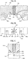
- FIGS. 6A and 6B show the spinning head 210.
- FIG. 6A is a cross-sectional view of the spinning head 210.
- FIG. 6B is a bottom view of the spinning head 210.
- the spinning head 210 includes an air jet portion 206, and a cylindrical spinning nozzle portion 205 disposed in the interior of the air injection portion 206.
- a spinning nozzle 201 extending in the direction of gravity and opening to the lower end surface of the spinning nozzle portion 205 is formed through the spinning nozzle portion 205.
- the nozzle hole diameter Nz of the spinning nozzle 201 may be set as desired, and may be, for example, in the range of 0.1 to 0.7 mm.
- the spinning head 210 is disposed above the conveyor belt 219 so that the spinning nozzle 201 is positioned substantially at the center in the width direction of the conveyor belt 219.
- the molten resin is supplied to the spinning nozzle 201 from above by a gear pump (not shown) or the like, and the supplied molten resin passes through the spinning nozzle 201 and extruded downward from the lower open end of the spinning nozzle 201, so that filaments 211 are formed (spun).
- the lower surface of the air jet portion 206 has a recess defined by two inclined surfaces 208a, 208b.
- the bottom surface of the recess constitutes a horizontal surface 207 orthogonal to the direction of gravity.
- One of the inclined surfaces 208a is located at one end of the horizontal surface 207 in the travel direction of the conveyor belt 219.
- the other inclined surface 208b is located at the other end of the horizontal surface 207 in the travel direction of the conveyor belt 219.
- the two inclined surfaces 208a, 208b are disposed symmetrically with respect to the plane orthogonal to the horizontal surface 207 and passing through the centerline of the spinning nozzle 201 so as to be inclined so that the distance between the inclined surfaces 208a, 208b gradually increases downward.
- the lower end surface of the spinning nozzle portion 205 is disposed so as to protrude from the horizontal surface 207 in a center portion of the horizontal surface 207 of the air jet portion 206.
- the protrusion amount H of the lower end surface of the spinning nozzle portion 205 from the horizontal surface 207 may be set as desired, and may be, for example, in the range of 0.01 to 1 mm.
- An annular primary air slit 202 configured to jet high-temperature primary air is formed between the outer circumferential surface of the spinning nozzle portion 205 and the air jet portion 206.
- the outer diameter of the spinning nozzle portion 205, that is, the inner diameter d of the primary air slit 202 may be set as desired, and may be, for example, 2.5 to 6 mm.
- slit-shaped flow paths are formed in the interior of the spinning head 210 in order mainly to homogenize the speed and temperature of the primary air jetted from the primary air slit 202. At least some of the intervals between the slit-shaped flow paths are in the range of 0.1 to 0.5 mm. Through the slit-shaped flow paths, the high-temperature primary air is supplied to the primary air slit 202.
- the high-temperature primary air When the high-temperature primary air is supplied to the primary air slit 202 from above, the high-temperature primary air passes through the primary air slit 202, and is jetted downward at a high speed from the open end, close to the horizontal surface 207, of the primary air slit 202. As the primary air is jetted from the primary air slit 202 at a high speed, a reduced pressure is generated below the lower end surface of the spinning nozzle portion 205, and this reduced pressure vibrates the filaments 211 extruded from the spinning nozzle 201.
- secondary air jet ports 204a, 204b configured to jet high-temperature secondary air are also formed in the air jet portion 206.
- the purpose of jetting the secondary air is to spread the filaments 211 vibrated by the primary air jetted from the primary air slit 202 and to orient the filaments 211 in one direction.
- Each of the secondary air jet ports 204a has an opening in the inclined surface 208a and extends inward in the air jet portion 206 in a direction orthogonal to the inclined surface 208a.
- each of the secondary air jet ports 204b has an opening in the inclined surface 208b and extends inward in the air jet portion 206 in a direction orthogonal to the inclined surface 208b.
- the secondary air jet ports 204a, 204b are disposed symmetrically with respect to the plane orthogonal to the horizontal surface 207 and passing through the centerline of the spinning nozzle 201.
- the diameter r of the secondary air jet ports 204a, 204b may be set as desired, and may preferably be in the range of 1.5 to 5 mm.
- the two secondary air jet ports 204a and two secondary air jet ports 204b are formed.
- the number of secondary air jet ports 204a, 204b is not limited thereto and may be set as desired.
- the secondary air jet ports 204a, 204b are configured to jet the secondary air slightly downward from the horizontal direction.
- the secondary air jetted from the secondary air jet ports 204a and the secondary air jetted from the secondary air jet ports 204b collide with each other below the spinning nozzle 201 and spread in the width direction of the conveyor belt 219. As a result, the falling, vibrating filaments 211 spread in the width direction of the conveyor belt 219.
- a plurality of small holes 203 are formed on the opposite sides across the spinning nozzle portion 205.
- Each small hole 203 has an opening in the horizontal surface 207 and extends in parallel to the spinning nozzle 201.
- the small holes 203 are lined up in a straight line orthogonal to the centerline of the spinning nozzle 201.
- the same number (three, in this example) of small holes 203 are formed on each of the opposite sides across the spinning nozzle portion 205, one of which is closer to the secondary air jet ports 204a and the other of which is closer to the secondary air jet ports 204b.
- the small holes 203 are configured to jet high-temperature air downward from the open ends in the horizontal surface 207, thereby contributing to stable spinning of the filaments 211.
- each small hole 203 may be set as desired, and may preferably be about 1 mm.
- the high-temperature air jetted from the small holes 203 may be introduced either from the source of the primary air to be jetted from the primary air slit 202, or from the source of the secondary air to be jetted from the secondary air jet ports 204a, 204b. Alternatively, high-temperature air other than the primary air and the secondary air may be supplied to the small holes 203.
- a pair of cooling nozzles 220 is provided between the spinning head 210 and the conveyor belt 219.
- one of the cooling nozzles 220 is disposed upstream of the filaments 211 spun from the spinning nozzle 201 in the travel direction of the conveyor belt 219.
- the other of the cooling nozzles 220 is disposed downstream of the filaments 211 spun from the spinning nozzle 201 in the travel direction of the conveyor belt 219.
- the cooling nozzles 220 spray water mist or the like onto the filaments 211 before the filaments 211 reach the conveyor belt 219, and thereby cool and solidify the filaments 211.
- the number and locations of the cooling nozzles 220 may be set as desired.
- the solidified filaments 211 are collected on the conveyor belt 219 so as to be oriented in the width direction of the conveyor belt 219. Thereby, the nonwoven web 218 formed of the filaments 211 oriented in the width direction is produced on the conveyor belt 219.
- the nonwoven web 218 produced on the conveyor belt 219 is conveyed by the conveyor belt 219 in the arrow direction of FIG. 5A , and then transversely drawn by the drawing device (not shown) up to 3 to 6 times longer than the original length. In this way, the transversely oriented filament nonwoven fabric is manufactured.
- FIGS. 7A to 7C show a modified example of the spinning head 210.
- FIG. 7A is a cross-sectional view of the spinning head 210 according to the modified example.
- FIG. 7B is a bottom view of the spinning head 210 according to the modified example.
- FIG. 7C is a cross-sectional view of the spinning head 210 according to the modified example, taken in the direction orthogonal to that of FIG. 7A .
- the small holes 203 are arranged in a circular pattern surrounding the spinning nozzle portion 205 (spinning nozzle 201).
- the small holes 203 are formed to be slightly inclined with respect to the horizontal plane, and high-temperature air is jetted from the small holes 203 in the arrow directions of FIG. 7B . High-temperature air jetted from such small holes 203 also contributes to stable spinning of the filaments 211.
- the average diameter of the filaments constituting the transversely oriented filament nonwoven fabric thus manufactured is in the range of 1 to 4 ⁇ m (preferably 2 to 3 ⁇ m).
- the variation coefficient of the diameter distribution of the filaments constituting the transversely oriented filament nonwoven fabric thus manufactured is in the range of 0.1 to 0.3.
- the transversely oriented filament nonwoven fabric may be slightly elastic in the direction parallel to the filaments, that is, in the transverse direction which coincides with the axial direction and the drawing direction of the filaments.
- the tensile strength in the transverse direction of the transversely oriented filament nonwoven fabric thus manufactured is 5 N/50mm or more, preferably 10 N/50mm or more, more preferably 20 N/50mm or more.
- a third embodiment of the nonwoven fabric for sound absorbing application according to the present invention is an orthogonally oriented nonwoven fabric including a plurality of first drawn filaments arranged and oriented in one direction, and a plurality of second drawn filaments arranged and oriented in a direction orthogonal to the one direction.
- Such an orthogonally oriented nonwoven fabric is basically formed by: (1) stacking and fusing the longitudinally oriented filament woven fabric and the transversely oriented filament nonwoven fabric together; (2) stacking and fusing two sheets of the longitudinally oriented filament nonwoven fabric together in an arrangement in which one of the sheets is rotated by 90° with respect to the other; or (3) stacking and fusing two sheets of the transversely oriented filament nonwoven fabric together in an arrangement in which one of the sheets is rotated by 90° with respect to the other.
- the present invention is not limited to these.
- such an orthogonally oriented nonwoven fabric may be formed by (4) stacking and fusing together the longitudinally oriented filament nonwoven fabric and a different transversely oriented filament nonwoven fabric.
- This different transversely oriented filament nonwoven fabric may have a basis weight substantially equal to that of the transversely oriented filament nonwoven fabric according to the second embodiment and may be formed of filaments having an average diameter greater than that of the transversely oriented filament nonwoven fabric according to the second embodiment.
- the fusing method used herein is not particularly limited, and fusion is generally through thermal compression using an embossing roller or the like.
- Longitudinally oriented filament nonwoven fabric was produced using the manufacturing apparatus shown in FIG. 3 .
- the meltblowing die was disposed orthogonal to the travel direction of the conveyor belt.
- a filament material thermoplastic resin
- a polyethylene terephthalate having an intrinsic viscosity (IV) of 0.53 and a melting point of 260°C manufactured by CHUNG SHING TEXTILE CO., LTD.
- Filaments were extruded from the meltblowing die with a discharge rate of 40 g/min per nozzle and a die temperature of 295°C.
- the high-speed airstream with a temperature of 400°C and a flow rate of 0.4 m 3 /min was generated for drafting the filaments extruded from the nozzles to reduce the filament diameter.
- the filaments were cooled by water mist or the like sprayed by the spray nozzles.
- the airstream vibration mechanism was disposed so that the minimum distance from a vertical extension of each nozzle of the meltblowing die was 20 mm.
- the airstream vibration mechanism was rotated at 900 rpm (which produced the vibration frequency of 15.0 Hz on the circumferential wall surface of the airstream vibration mechanism).
- the filaments oriented in the longitudinal direction were collected on the conveyor belt.
- the filaments collected on the conveyor belt were heated and longitudinally drawn to be 4.5 times longer than the original length by the drawing cylinders.
- a longitudinally oriented filament nonwoven fabric was produced.
- a longitudinally oriented filament nonwoven fabric having a grammage of 5 to 40 g/m 2 was produced.
- the longitudinally oriented filament nonwoven fabric having a grammage of 5 to 40 g/m 2 was produced in this example, it has been confirmed that by appropriately changing the travel speed of the conveyor belt, it is possible to produce a longitudinally oriented filament nonwoven fabric having a grammage up to 60 g/m 2 .
- FIG. 8 shows the physical properties of the resulting longitudinally oriented filament nonwoven fabric.
- FIG. 9 shows the filament diameter distribution of a longitudinally oriented filament nonwoven fabric having a grammage of 10 g/m 2 and the filament diameter distribution of a longitudinally oriented filament nonwoven fabric having a grammage of 20 g/m 2 .
- the mode value of the filament diameter distribution was about 2.5 ⁇ m and the average filament diameter was also about 2.5 ⁇ m. It is considered that, in the longitudinally oriented filament nonwoven fabric having any grammage within the range of 5 to 60 g/m 2 , the mode value of the filament diameter distribution and average filament diameter would be substantially the same as those of FIG. 9 since such variations in grammage can be obtained simply by changing the travel speed of the conveyor belt during manufacture.
- PET felt PET sound absorbing sheet
- the thickness of the PET felt was 10 mm and the basis weight of the PET felt was 230 g/m 2 .
- Example 1 (“nonwoven fabric (5 g)" + “PET felt”) was prepared by disposing a longitudinally oriented filament nonwoven fabric having a grammage of 5 g/m 2 on a surface of the PET felt.
- Example 2 (“nonwoven fabric (10 g)” + “PET felt”) was prepared by disposing longitudinally oriented filament nonwoven fabric having a grammage of 10 g/m 2 on a surface of the PET felt.
- Example 3 (“nonwoven fabric (15 g)” + “PET felt”) was prepared by disposing longitudinally oriented filament nonwoven fabric having a grammage of 15 g/m 2 on a surface of the PET felt.
- Example 4 (“nonwoven fabric (20 g)" + “PET felt”) was prepared by disposing longitudinally oriented filament nonwoven fabric having a grammage of 20 g/m 2 on a surface of the PET felt.
- Example 5 (“nonwoven fabric (40 g)” + “PET felt”) was prepared by disposing longitudinally oriented filament nonwoven fabric having a grammage of 40 g/m 2 on a surface of the PET felt.
- Comparative Example 1 (“PET felt” alone) was prepared as the PET felt alone.
- Comparative Example 2 (“nonwoven fabric” alone) was prepared as the longitudinally oriented filament nonwoven fabric alone. Note that it was confirmed that the sound absorption performance of the longitudinally oriented filament nonwoven fabric alone did not depend substantially on variations in grammage within the range of 5 to 60 g/m 2 .
- Reference Example 1 (“nonwoven fabric (20 g)" ⁇ 3 + "PET felt”) was prepared by disposing three sheets of the longitudinally oriented filament nonwoven fabric having a grammage of 20 g/m 2 in a random fashion on a surface of the PET felt.
- FIG. 10 shows the measurements of the normal incident sound absorption coefficient for Examples 1 to 5 and Comparative Examples 1 and 2.
- FIG. 11 shows the measurements of the normal incident sound absorption coefficient for Example 4, Comparative Example 1, and Reference Example 1.
- a nonwoven fabric which includes a plurality of drawn filaments arranged and oriented in one direction, and in which the mode value of the diameter distribution of the filaments is 1 to 4 ⁇ m is suitable as a component of a sound absorbing material.
- such nonwoven fabric when laminated on a porous sound absorbing material, constitutes a sound absorbing material with the porous sound absorbing material, and the resultant laminated sound absorbing material has significantly improved sound absorption performance as compared to the porous sound absorbing material alone.
- a sound absorbing material containing the nonwoven fabric for sound absorbing application according to the present invention may be used in a variety of applications.
- Example applications of the sound absorbing material containing the nonwoven fabric for sound absorbing application according to the present invention may include a sound absorbing material for an engine room and for an interior of an automobile, a sound absorbing protective material for automobiles, for household electrical appliances, and for various motors, etc., a sound absorbing material to be installed in walls, floors, ceilings, etc. of various buildings, a sound absorbing material for interior use in machine rooms etc., a sound absorbing material for various sound insulating walls, and/or a sound absorbing material for office equipment such as copiers and multifunction machines.
Landscapes
- Engineering & Computer Science (AREA)
- Textile Engineering (AREA)
- Physics & Mathematics (AREA)
- Acoustics & Sound (AREA)
- Multimedia (AREA)
- Chemical & Material Sciences (AREA)
- Chemical Kinetics & Catalysis (AREA)
- Nonwoven Fabrics (AREA)
- Laminated Bodies (AREA)
- Soundproofing, Sound Blocking, And Sound Damping (AREA)
- Building Environments (AREA)
- Vehicle Interior And Exterior Ornaments, Soundproofing, And Insulation (AREA)
Applications Claiming Priority (3)
| Application Number | Priority Date | Filing Date | Title |
|---|---|---|---|
| JP2016230410 | 2016-11-28 | ||
| JP2017154343A JP2018092131A (ja) | 2016-11-28 | 2017-08-09 | 吸音材用不織布及びそれを用いた吸音材 |
| PCT/JP2017/042683 WO2018097326A1 (ja) | 2016-11-28 | 2017-11-28 | 吸音材用不織布及びそれを用いた吸音材 |
Publications (3)
| Publication Number | Publication Date |
|---|---|
| EP3547307A1 true EP3547307A1 (de) | 2019-10-02 |
| EP3547307A4 EP3547307A4 (de) | 2020-06-17 |
| EP3547307B1 EP3547307B1 (de) | 2021-07-14 |
Family
ID=62565978
Family Applications (1)
| Application Number | Title | Priority Date | Filing Date |
|---|---|---|---|
| EP17874030.4A Active EP3547307B1 (de) | 2016-11-28 | 2017-11-28 | Vliesstoff für ein schallabsorbierendes material und schallabsorbierendes material damit |
Country Status (4)
| Country | Link |
|---|---|
| US (1) | US20190279609A1 (de) |
| EP (1) | EP3547307B1 (de) |
| JP (1) | JP2018092131A (de) |
| CN (1) | CN110024022A (de) |
Families Citing this family (2)
| Publication number | Priority date | Publication date | Assignee | Title |
|---|---|---|---|---|
| JP7333189B2 (ja) * | 2019-04-03 | 2023-08-24 | Eneos株式会社 | 吸音材 |
| CN111716859A (zh) * | 2020-06-12 | 2020-09-29 | 广西德福特科技有限公司 | 一种三组份吸音棉及其制备方法 |
Family Cites Families (17)
| Publication number | Priority date | Publication date | Assignee | Title |
|---|---|---|---|---|
| US5366793A (en) * | 1992-04-07 | 1994-11-22 | Kimberly Clark Co | Anisotropic nonwoven fibrous web |
| JPH10240269A (ja) * | 1997-02-25 | 1998-09-11 | Matsushita Electric Works Ltd | 吸音材及びその製造方法 |
| JP4128743B2 (ja) * | 1998-03-03 | 2008-07-30 | リーター アウトモーティブ (インターナツィオナール) アクティエン ゲゼルシャフト | 吸音性を有する薄層ラミネート |
| JP2000334867A (ja) * | 1999-05-31 | 2000-12-05 | Nippon Petrochem Co Ltd | 積層体、該積層体を有する構造体、前記積層体の製造方法、および前記構造体の製造方法 |
| US6524521B1 (en) * | 1999-08-30 | 2003-02-25 | Nippon Petrochemicals Co., Ltd. | Method of and apparatus for manufacturing longitudinally aligned nonwoven fabric |
| US6548431B1 (en) * | 1999-12-20 | 2003-04-15 | E. I. Du Pont De Nemours And Company | Melt spun polyester nonwoven sheet |
| JP4495871B2 (ja) * | 2001-02-27 | 2010-07-07 | 新日本石油株式会社 | 横配列ウェブの製造方法および装置 |
| JP2004076237A (ja) * | 2002-08-22 | 2004-03-11 | Nippon Petrochemicals Co Ltd | 強化延伸不織布 |
| ZA200601215B (en) * | 2003-08-25 | 2007-05-30 | Takayasu Co Ltd | Sound absorbing material |
| JP2008008997A (ja) * | 2006-06-27 | 2008-01-17 | Bridgestone Kbg Co Ltd | 複合吸音構造体 |
| JP2008036880A (ja) * | 2006-08-02 | 2008-02-21 | Daiwabo Co Ltd | 積層不織布、ゲル化シート及びフィラー固着シート |
| JP2009275801A (ja) * | 2008-05-14 | 2009-11-26 | Nippon Oil Corp | 真空断熱材、及びその製造方法 |
| JP5661333B2 (ja) * | 2010-05-26 | 2015-01-28 | Jx日鉱日石エネルギー株式会社 | 一方向伸縮性基材及び複合伸縮性シート、並びにそれらの製造方法 |
| JP5679089B1 (ja) * | 2013-03-07 | 2015-03-04 | 三菱レイヨン株式会社 | 炭素繊維強化熱可塑性樹脂複合材料、及びそれを用いた成型体 |
| JP6761618B2 (ja) * | 2013-12-23 | 2020-09-30 | 日本バイリーン株式会社 | 吸音材 |
| US9309612B2 (en) * | 2014-05-07 | 2016-04-12 | Biax-Fiberfilm | Process for forming a non-woven web |
| JP6968614B2 (ja) * | 2016-11-28 | 2021-11-17 | Eneos株式会社 | 不織布製吸音材 |
-
2017
- 2017-08-09 JP JP2017154343A patent/JP2018092131A/ja active Pending
- 2017-11-28 US US16/463,067 patent/US20190279609A1/en not_active Abandoned
- 2017-11-28 EP EP17874030.4A patent/EP3547307B1/de active Active
- 2017-11-28 CN CN201780073169.1A patent/CN110024022A/zh active Pending
Also Published As
| Publication number | Publication date |
|---|---|
| EP3547307B1 (de) | 2021-07-14 |
| US20190279609A1 (en) | 2019-09-12 |
| CN110024022A (zh) | 2019-07-16 |
| EP3547307A4 (de) | 2020-06-17 |
| JP2018092131A (ja) | 2018-06-14 |
Similar Documents
| Publication | Publication Date | Title |
|---|---|---|
| US6524521B1 (en) | Method of and apparatus for manufacturing longitudinally aligned nonwoven fabric | |
| TWI427201B (zh) | 製造複合線的方法及裝置 | |
| EP3547307B1 (de) | Vliesstoff für ein schallabsorbierendes material und schallabsorbierendes material damit | |
| US11705098B2 (en) | Sound absorbing material | |
| EP3547306B1 (de) | Schallabsorbierendes material mit vliesstoff | |
| US20200216981A1 (en) | Apparatus For Manufacturing Ultrafine Fiber And Method For Manufacturing Ultrafine Fiber | |
| WO2018097326A1 (ja) | 吸音材用不織布及びそれを用いた吸音材 | |
| JP5305961B2 (ja) | 極細繊維不織布 | |
| JP6716380B2 (ja) | 長繊維不織布 | |
| US20220199063A1 (en) | Sound-absorbing material | |
| WO2018097327A1 (ja) | 不織布製吸音材 | |
| JP2006296463A (ja) | カーテン用基布およびカーテン | |
| WO2017170791A1 (ja) | 耐熱性繊維構造体 | |
| KR20130117793A (ko) | 고-균일성 스펀본디드 부직포 | |
| WO2017068811A1 (ja) | ナノファイバー不織布及びそれを用いた吸音材 | |
| CN112236060A (zh) | 帘用无纺布及其制造方法 | |
| KR20210038842A (ko) | 적층 흡음재 | |
| JP7419637B2 (ja) | メルトブロー不織布及びその製造方法 | |
| JP2019001005A (ja) | 複合不織布 | |
| JP7468255B2 (ja) | 吸音材用不織布、吸音材、および吸音材用不織布の製造方法 | |
| JP7427435B2 (ja) | 長繊維不織布 | |
| JP2020121289A (ja) | 粉塵捕集用網状構造体 |
Legal Events
| Date | Code | Title | Description |
|---|---|---|---|
| STAA | Information on the status of an ep patent application or granted ep patent |
Free format text: STATUS: THE INTERNATIONAL PUBLICATION HAS BEEN MADE |
|
| PUAI | Public reference made under article 153(3) epc to a published international application that has entered the european phase |
Free format text: ORIGINAL CODE: 0009012 |
|
| STAA | Information on the status of an ep patent application or granted ep patent |
Free format text: STATUS: REQUEST FOR EXAMINATION WAS MADE |
|
| 17P | Request for examination filed |
Effective date: 20190626 |
|
| AK | Designated contracting states |
Kind code of ref document: A1 Designated state(s): AL AT BE BG CH CY CZ DE DK EE ES FI FR GB GR HR HU IE IS IT LI LT LU LV MC MK MT NL NO PL PT RO RS SE SI SK SM TR |
|
| AX | Request for extension of the european patent |
Extension state: BA ME |
|
| DAV | Request for validation of the european patent (deleted) | ||
| DAX | Request for extension of the european patent (deleted) | ||
| A4 | Supplementary search report drawn up and despatched |
Effective date: 20200515 |
|
| RIC1 | Information provided on ipc code assigned before grant |
Ipc: D04H 3/007 20120101ALI20200511BHEP Ipc: G10K 11/162 20060101AFI20200511BHEP Ipc: D04H 3/04 20120101ALI20200511BHEP Ipc: G10K 11/16 20060101ALI20200511BHEP Ipc: D04H 3/011 20120101ALI20200511BHEP Ipc: G10K 11/168 20060101ALI20200511BHEP Ipc: D04H 3/016 20120101ALI20200511BHEP |
|
| REG | Reference to a national code |
Ref country code: DE Ref legal event code: R079 Ref document number: 602017042297 Country of ref document: DE Free format text: PREVIOUS MAIN CLASS: G10K0011162000 Ipc: D04H0003016000 |
|
| RIC1 | Information provided on ipc code assigned before grant |
Ipc: D04H 3/016 20120101AFI20201218BHEP Ipc: G10K 11/162 20060101ALN20201218BHEP Ipc: B32B 5/26 20060101ALI20201218BHEP Ipc: D04H 3/14 20120101ALI20201218BHEP Ipc: B32B 5/02 20060101ALI20201218BHEP Ipc: G10K 11/168 20060101ALN20201218BHEP Ipc: D04H 3/04 20120101ALI20201218BHEP Ipc: B60R 13/08 20060101ALI20201218BHEP |
|
| GRAP | Despatch of communication of intention to grant a patent |
Free format text: ORIGINAL CODE: EPIDOSNIGR1 |
|
| STAA | Information on the status of an ep patent application or granted ep patent |
Free format text: STATUS: GRANT OF PATENT IS INTENDED |
|
| INTG | Intention to grant announced |
Effective date: 20210203 |
|
| GRAS | Grant fee paid |
Free format text: ORIGINAL CODE: EPIDOSNIGR3 |
|
| GRAA | (expected) grant |
Free format text: ORIGINAL CODE: 0009210 |
|
| STAA | Information on the status of an ep patent application or granted ep patent |
Free format text: STATUS: THE PATENT HAS BEEN GRANTED |
|
| AK | Designated contracting states |
Kind code of ref document: B1 Designated state(s): AL AT BE BG CH CY CZ DE DK EE ES FI FR GB GR HR HU IE IS IT LI LT LU LV MC MK MT NL NO PL PT RO RS SE SI SK SM TR |
|
| REG | Reference to a national code |
Ref country code: GB Ref legal event code: FG4D |
|
| REG | Reference to a national code |
Ref country code: DE Ref legal event code: R096 Ref document number: 602017042297 Country of ref document: DE |
|
| REG | Reference to a national code |
Ref country code: IE Ref legal event code: FG4D |
|
| REG | Reference to a national code |
Ref country code: AT Ref legal event code: REF Ref document number: 1410740 Country of ref document: AT Kind code of ref document: T Effective date: 20210815 |
|
| REG | Reference to a national code |
Ref country code: LT Ref legal event code: MG9D |
|
| REG | Reference to a national code |
Ref country code: NL Ref legal event code: MP Effective date: 20210714 |
|
| REG | Reference to a national code |
Ref country code: AT Ref legal event code: MK05 Ref document number: 1410740 Country of ref document: AT Kind code of ref document: T Effective date: 20210714 |
|
| PG25 | Lapsed in a contracting state [announced via postgrant information from national office to epo] |
Ref country code: RS Free format text: LAPSE BECAUSE OF FAILURE TO SUBMIT A TRANSLATION OF THE DESCRIPTION OR TO PAY THE FEE WITHIN THE PRESCRIBED TIME-LIMIT Effective date: 20210714 Ref country code: SE Free format text: LAPSE BECAUSE OF FAILURE TO SUBMIT A TRANSLATION OF THE DESCRIPTION OR TO PAY THE FEE WITHIN THE PRESCRIBED TIME-LIMIT Effective date: 20210714 Ref country code: HR Free format text: LAPSE BECAUSE OF FAILURE TO SUBMIT A TRANSLATION OF THE DESCRIPTION OR TO PAY THE FEE WITHIN THE PRESCRIBED TIME-LIMIT Effective date: 20210714 Ref country code: FI Free format text: LAPSE BECAUSE OF FAILURE TO SUBMIT A TRANSLATION OF THE DESCRIPTION OR TO PAY THE FEE WITHIN THE PRESCRIBED TIME-LIMIT Effective date: 20210714 Ref country code: ES Free format text: LAPSE BECAUSE OF FAILURE TO SUBMIT A TRANSLATION OF THE DESCRIPTION OR TO PAY THE FEE WITHIN THE PRESCRIBED TIME-LIMIT Effective date: 20210714 Ref country code: LT Free format text: LAPSE BECAUSE OF FAILURE TO SUBMIT A TRANSLATION OF THE DESCRIPTION OR TO PAY THE FEE WITHIN THE PRESCRIBED TIME-LIMIT Effective date: 20210714 Ref country code: BG Free format text: LAPSE BECAUSE OF FAILURE TO SUBMIT A TRANSLATION OF THE DESCRIPTION OR TO PAY THE FEE WITHIN THE PRESCRIBED TIME-LIMIT Effective date: 20211014 Ref country code: AT Free format text: LAPSE BECAUSE OF FAILURE TO SUBMIT A TRANSLATION OF THE DESCRIPTION OR TO PAY THE FEE WITHIN THE PRESCRIBED TIME-LIMIT Effective date: 20210714 Ref country code: PT Free format text: LAPSE BECAUSE OF FAILURE TO SUBMIT A TRANSLATION OF THE DESCRIPTION OR TO PAY THE FEE WITHIN THE PRESCRIBED TIME-LIMIT Effective date: 20211115 Ref country code: NL Free format text: LAPSE BECAUSE OF FAILURE TO SUBMIT A TRANSLATION OF THE DESCRIPTION OR TO PAY THE FEE WITHIN THE PRESCRIBED TIME-LIMIT Effective date: 20210714 Ref country code: NO Free format text: LAPSE BECAUSE OF FAILURE TO SUBMIT A TRANSLATION OF THE DESCRIPTION OR TO PAY THE FEE WITHIN THE PRESCRIBED TIME-LIMIT Effective date: 20211014 |
|
| PG25 | Lapsed in a contracting state [announced via postgrant information from national office to epo] |
Ref country code: PL Free format text: LAPSE BECAUSE OF FAILURE TO SUBMIT A TRANSLATION OF THE DESCRIPTION OR TO PAY THE FEE WITHIN THE PRESCRIBED TIME-LIMIT Effective date: 20210714 Ref country code: LV Free format text: LAPSE BECAUSE OF FAILURE TO SUBMIT A TRANSLATION OF THE DESCRIPTION OR TO PAY THE FEE WITHIN THE PRESCRIBED TIME-LIMIT Effective date: 20210714 Ref country code: GR Free format text: LAPSE BECAUSE OF FAILURE TO SUBMIT A TRANSLATION OF THE DESCRIPTION OR TO PAY THE FEE WITHIN THE PRESCRIBED TIME-LIMIT Effective date: 20211015 |
|
| REG | Reference to a national code |
Ref country code: DE Ref legal event code: R097 Ref document number: 602017042297 Country of ref document: DE |
|
| PG25 | Lapsed in a contracting state [announced via postgrant information from national office to epo] |
Ref country code: DK Free format text: LAPSE BECAUSE OF FAILURE TO SUBMIT A TRANSLATION OF THE DESCRIPTION OR TO PAY THE FEE WITHIN THE PRESCRIBED TIME-LIMIT Effective date: 20210714 |
|
| PLBE | No opposition filed within time limit |
Free format text: ORIGINAL CODE: 0009261 |
|
| STAA | Information on the status of an ep patent application or granted ep patent |
Free format text: STATUS: NO OPPOSITION FILED WITHIN TIME LIMIT |
|
| PG25 | Lapsed in a contracting state [announced via postgrant information from national office to epo] |
Ref country code: SM Free format text: LAPSE BECAUSE OF FAILURE TO SUBMIT A TRANSLATION OF THE DESCRIPTION OR TO PAY THE FEE WITHIN THE PRESCRIBED TIME-LIMIT Effective date: 20210714 Ref country code: SK Free format text: LAPSE BECAUSE OF FAILURE TO SUBMIT A TRANSLATION OF THE DESCRIPTION OR TO PAY THE FEE WITHIN THE PRESCRIBED TIME-LIMIT Effective date: 20210714 Ref country code: RO Free format text: LAPSE BECAUSE OF FAILURE TO SUBMIT A TRANSLATION OF THE DESCRIPTION OR TO PAY THE FEE WITHIN THE PRESCRIBED TIME-LIMIT Effective date: 20210714 Ref country code: EE Free format text: LAPSE BECAUSE OF FAILURE TO SUBMIT A TRANSLATION OF THE DESCRIPTION OR TO PAY THE FEE WITHIN THE PRESCRIBED TIME-LIMIT Effective date: 20210714 Ref country code: CZ Free format text: LAPSE BECAUSE OF FAILURE TO SUBMIT A TRANSLATION OF THE DESCRIPTION OR TO PAY THE FEE WITHIN THE PRESCRIBED TIME-LIMIT Effective date: 20210714 Ref country code: AL Free format text: LAPSE BECAUSE OF FAILURE TO SUBMIT A TRANSLATION OF THE DESCRIPTION OR TO PAY THE FEE WITHIN THE PRESCRIBED TIME-LIMIT Effective date: 20210714 |
|
| 26N | No opposition filed |
Effective date: 20220419 |
|
| PG25 | Lapsed in a contracting state [announced via postgrant information from national office to epo] |
Ref country code: MC Free format text: LAPSE BECAUSE OF FAILURE TO SUBMIT A TRANSLATION OF THE DESCRIPTION OR TO PAY THE FEE WITHIN THE PRESCRIBED TIME-LIMIT Effective date: 20210714 |
|
| REG | Reference to a national code |
Ref country code: CH Ref legal event code: PL |
|
| GBPC | Gb: european patent ceased through non-payment of renewal fee |
Effective date: 20211128 |
|
| PG25 | Lapsed in a contracting state [announced via postgrant information from national office to epo] |
Ref country code: LU Free format text: LAPSE BECAUSE OF NON-PAYMENT OF DUE FEES Effective date: 20211128 Ref country code: IT Free format text: LAPSE BECAUSE OF FAILURE TO SUBMIT A TRANSLATION OF THE DESCRIPTION OR TO PAY THE FEE WITHIN THE PRESCRIBED TIME-LIMIT Effective date: 20210714 Ref country code: BE Free format text: LAPSE BECAUSE OF NON-PAYMENT OF DUE FEES Effective date: 20211130 |
|
| REG | Reference to a national code |
Ref country code: BE Ref legal event code: MM Effective date: 20211130 |
|
| PG25 | Lapsed in a contracting state [announced via postgrant information from national office to epo] |
Ref country code: IE Free format text: LAPSE BECAUSE OF NON-PAYMENT OF DUE FEES Effective date: 20211128 Ref country code: GB Free format text: LAPSE BECAUSE OF NON-PAYMENT OF DUE FEES Effective date: 20211128 |
|
| PG25 | Lapsed in a contracting state [announced via postgrant information from national office to epo] |
Ref country code: FR Free format text: LAPSE BECAUSE OF NON-PAYMENT OF DUE FEES Effective date: 20211130 |
|
| PG25 | Lapsed in a contracting state [announced via postgrant information from national office to epo] |
Ref country code: CY Free format text: LAPSE BECAUSE OF FAILURE TO SUBMIT A TRANSLATION OF THE DESCRIPTION OR TO PAY THE FEE WITHIN THE PRESCRIBED TIME-LIMIT Effective date: 20210714 |
|
| PG25 | Lapsed in a contracting state [announced via postgrant information from national office to epo] |
Ref country code: LI Free format text: LAPSE BECAUSE OF NON-PAYMENT OF DUE FEES Effective date: 20220701 Ref country code: HU Free format text: LAPSE BECAUSE OF FAILURE TO SUBMIT A TRANSLATION OF THE DESCRIPTION OR TO PAY THE FEE WITHIN THE PRESCRIBED TIME-LIMIT; INVALID AB INITIO Effective date: 20171128 Ref country code: CH Free format text: LAPSE BECAUSE OF NON-PAYMENT OF DUE FEES Effective date: 20220701 |
|
| REG | Reference to a national code |
Ref country code: DE Ref legal event code: R081 Ref document number: 602017042297 Country of ref document: DE Owner name: ENEOS CORP., JP Free format text: FORMER OWNER: JXTG NIPPON OIL & ENERGY CORPORATION, TOKYO, JP |
|
| PGFP | Annual fee paid to national office [announced via postgrant information from national office to epo] |
Ref country code: DE Payment date: 20231129 Year of fee payment: 7 |
|
| PG25 | Lapsed in a contracting state [announced via postgrant information from national office to epo] |
Ref country code: MK Free format text: LAPSE BECAUSE OF FAILURE TO SUBMIT A TRANSLATION OF THE DESCRIPTION OR TO PAY THE FEE WITHIN THE PRESCRIBED TIME-LIMIT Effective date: 20210714 |