EP3546163A1 - Machine et procédé d'usinage conique, en particulier de rabotage conique, des pièces en bois, en matière plastique et analogue - Google Patents
Machine et procédé d'usinage conique, en particulier de rabotage conique, des pièces en bois, en matière plastique et analogue Download PDFInfo
- Publication number
- EP3546163A1 EP3546163A1 EP19000148.7A EP19000148A EP3546163A1 EP 3546163 A1 EP3546163 A1 EP 3546163A1 EP 19000148 A EP19000148 A EP 19000148A EP 3546163 A1 EP3546163 A1 EP 3546163A1
- Authority
- EP
- European Patent Office
- Prior art keywords
- workpiece
- workpieces
- machine
- transport direction
- tool
- Prior art date
- Legal status (The legal status is an assumption and is not a legal conclusion. Google has not performed a legal analysis and makes no representation as to the accuracy of the status listed.)
- Pending
Links
Images


Classifications
-
- B—PERFORMING OPERATIONS; TRANSPORTING
- B27—WORKING OR PRESERVING WOOD OR SIMILAR MATERIAL; NAILING OR STAPLING MACHINES IN GENERAL
- B27F—DOVETAILED WORK; TENONS; SLOTTING MACHINES FOR WOOD OR SIMILAR MATERIAL; NAILING OR STAPLING MACHINES
- B27F1/00—Dovetailed work; Tenons; Making tongues or grooves; Groove- and- tongue jointed work; Finger- joints
- B27F1/02—Making tongues or grooves, of indefinite length
- B27F1/06—Making tongues or grooves, of indefinite length simultaneously along opposite edges of a board
-
- B—PERFORMING OPERATIONS; TRANSPORTING
- B27—WORKING OR PRESERVING WOOD OR SIMILAR MATERIAL; NAILING OR STAPLING MACHINES IN GENERAL
- B27C—PLANING, DRILLING, MILLING, TURNING OR UNIVERSAL MACHINES FOR WOOD OR SIMILAR MATERIAL
- B27C5/00—Machines designed for producing special profiles or shaped work, e.g. by rotary cutters; Equipment therefor
- B27C5/02—Machines with table
- B27C5/06—Arrangements for clamping or feeding work
-
- B—PERFORMING OPERATIONS; TRANSPORTING
- B27—WORKING OR PRESERVING WOOD OR SIMILAR MATERIAL; NAILING OR STAPLING MACHINES IN GENERAL
- B27F—DOVETAILED WORK; TENONS; SLOTTING MACHINES FOR WOOD OR SIMILAR MATERIAL; NAILING OR STAPLING MACHINES
- B27F5/00—Slotted or mortised work
- B27F5/02—Slotting or mortising machines tools therefor
- B27F5/026—Slotting a workpiece before introducing into said slot a guide which belongs to a following working device, and which is parallel to the feed movement of this working device
-
- B—PERFORMING OPERATIONS; TRANSPORTING
- B27—WORKING OR PRESERVING WOOD OR SIMILAR MATERIAL; NAILING OR STAPLING MACHINES IN GENERAL
- B27B—SAWS FOR WOOD OR SIMILAR MATERIAL; COMPONENTS OR ACCESSORIES THEREFOR
- B27B5/00—Sawing machines working with circular or cylindrical saw blades; Components or equipment therefor
- B27B5/29—Details; Component parts; Accessories
-
- B—PERFORMING OPERATIONS; TRANSPORTING
- B27—WORKING OR PRESERVING WOOD OR SIMILAR MATERIAL; NAILING OR STAPLING MACHINES IN GENERAL
- B27B—SAWS FOR WOOD OR SIMILAR MATERIAL; COMPONENTS OR ACCESSORIES THEREFOR
- B27B7/00—Sawing machines working with circular saw blades, specially designed for length sawing of trunks
-
- B—PERFORMING OPERATIONS; TRANSPORTING
- B27—WORKING OR PRESERVING WOOD OR SIMILAR MATERIAL; NAILING OR STAPLING MACHINES IN GENERAL
- B27M—WORKING OF WOOD NOT PROVIDED FOR IN SUBCLASSES B27B - B27L; MANUFACTURE OF SPECIFIC WOODEN ARTICLES
- B27M3/00—Manufacture or reconditioning of specific semi-finished or finished articles
- B27M3/0013—Manufacture or reconditioning of specific semi-finished or finished articles of composite or compound articles
- B27M3/0026—Manufacture or reconditioning of specific semi-finished or finished articles of composite or compound articles characterised by oblong elements connected laterally
Definitions
- the invention relates to a machine for conical machining, in particular for conical planing of workpieces made of wood, plastic and the like according to the preamble of claim 1 and a method for processing such workpieces according to the preamble of claim 11.
- conical workpieces which are usually lamellar workpieces or boards with parallel upper and lower sides and conically straight tapered longitudinal sides, glued to each other with these cone sides contiguous.
- the plate-like elements thus obtained can be superimposed to form, for example, walls in this way. So that the conical workpieces can be put together cleanly, it is necessary to cleanly machine the corresponding sides of the starting workpieces, which may be sawed un-sawn or edged boards due to the natural growth form of the tree trunks. For this purpose, these workpiece sides are planed by tools, in particular rotating cutter heads. However, it is difficult to transport the workpieces through a machine so that the required high accuracy and / or surface quality can be easily achieved.
- the invention has the object of providing the generic machine and the generic method in such a way that the workpieces can be processed in a simple manner with high accuracy and / or quality.
- the machine according to the invention is characterized in that the workpieces are transported by the groove-web guide in the transport direction through the machine.
- the corresponding longitudinal sides of the workpiece can be processed with high accuracy and / or quality.
- a high glueable quality can be achieved, so that the workpieces are properly assembled after their processing to sheet-like elements by being pressed against each other with their glued longitudinal sides together.
- the groove-web guide has at least one web extending in the transport direction, which engages in a groove of the workpiece which is provided on the workpiece and also runs in the transport direction.
- the web thus forms a guide web, with which the workpieces are properly guided during transport through the machine.
- the corresponding two tools can be adjusted or adjusted during transport that the rectilinear conical machining with optimal chip removal takes place on these sides of the workpiece.
- the groove can be very easily attached to the workpiece and, in conjunction with the machine-side web ensures that the workpiece can be transported through the machine exactly aligned.
- the machine-side web is provided on the machine-side support for the workpieces.
- the support is formed by a machine table.
- the workpieces can be easily transported through the machine on top of them.
- the machine-side web extends at least up to the level of the tools with which the right and left side of the workpiece are processed in the transport direction.
- the web extends beyond the position of these tools, advantageously over the entire length of the support. Then it is reliably avoided that the workpiece during processing by the lateral tools performs unintentional movements that would affect the surface accuracy.
- This further tool is in an advantageous embodiment, a horizontally arranged, rotatably driven dressing tool.
- the groove is produced during transport of the workpiece by the machine in the bottom of the workpiece, for example milled.
- the dressing tool in such a way that with him in addition, the corresponding side of the workpiece can be trained.
- measuring elements which capture at least the one side of the workpiece lying in the direction of transport are connected to the CNC control.
- the measuring elements are formed by sensors that can detect the corresponding workpiece side and thus virtually a width profile of the starting workpiece contactless.
- the measuring elements it is also possible to use as measuring elements a camera, measuring wheels, measuring rollers or measuring skids, which rest against the corresponding sides of the workpiece during the transport of the workpiece through the machine and also pass their signals to the CNC control.
- the CNC control is advantageously designed so that it evaluates the signals received from the measuring elements and adjusts the tools transversely to the transport direction in accordance with the evaluation.
- the conical workpieces can be fed to the machine aligned so that, for example, the right side of the workpiece in the transport direction is parallel to the transport direction.
- the associated tool only has to be set to the position required for optimum chip removal on this side of the workpiece. During transport of the workpiece through the machine, this tool stops.
- both sides of the workpiece are at an angle to the transport direction, of course, both tools during transport through the machine depending on the feed path of the workpiece by the CNC control continuously adjusted transversely to the transport direction.
- measuring elements can be used, for example, in the form of running on the top of the workpieces measuring wheels.
- At least one further sensor can be provided to detect the start of the workpiece.
- the machine is designed in a preferred embodiment so that the support is preceded by at least one dressing table. It is provided with at least one in the transport direction extending stop on which the workpiece, before it is processed with the two tools, comes to rest.
- the measuring elements with which the right and left sides of the workpiece are detected in the transport direction are advantageously located in the region of this dressing table.
- the tool or tools can be adjusted in time to the required chip removal positions, measured in the transport direction of the workpieces distance between the measuring elements and the first tool, which engages with the workpiece, greater than the length of the workpieces.
- the workpieces are before or during their supply in terms of at least the taper to be machined measured.
- On the workpiece preferably after the measurement, at least one in the transport direction of the workpiece extending positive locking element is attached.
- the positive-locking element cooperates with at least one counter-form-locking element. It extends in the transport direction of the workpiece.
- the tool is adjusted transversely to the transport direction in dependence on the determined conicity of the workpiece.
- the position of the workpiece relative to the tool is detected.
- the tool can be optimally adjusted during the workpiece pass, so that a high quality and / or the desired conicity of the workpiece longitudinal side is achieved with minimal chip removal. If these conical workpieces are subsequently placed against one another to form plate-shaped elements and glued together, the high quality of the corresponding workpiece side ensures that the workpieces adjoining one another with these longitudinal sides and glued together can be properly firmly connected to one another.
- the width and / or the conicity of the workpiece is detected by measuring elements whose signals are fed to a controller for the tools.
- the workpieces are advantageously placed in pairs in pairs of planks by each rotating a workpiece through 180 ° about an axis perpendicular to its longitudinal axis.
- the pairs of boards thus formed have parallel longitudinal sides and approximately rectangular outline.
- the workpieces can be glued together on their adjacent longitudinal sides; however, this advantageously takes place only in a subsequent method step.
- the pairs of boards become a board carpet abutting and suitably connected together, preferably glued together.
- the pairs of boards thus achieved are advantageously placed against one another to form an endless board carpet and firmly joined together, preferably glued.
- the boards are loaded transversely to their longitudinal sides and pressed transversely to their top and bottom. Since the pairs of boards have parallel outer longitudinal sides, a straight board carpet is formed.
- the workpieces are divided into two workpiece parts after the conical machining.
- one of the two workpiece parts is rotated and forms with the other workpiece part, the pair of boards with parallel longitudinal sides and approximately rectangular outline.
- the division of the finished workpieces can be done in two ways.
- the workpieces are separated after the conical machining in half length to form the two workpiece parts.
- the workpieces are separated after the conical machining in an axis parallel to the symmetry or longitudinal axis of the workpiece to form the two workpiece parts, for example by means of a saw.
- the two workpiece parts have the same length as the workpiece.
- the conical machining of the two longitudinal sides takes place symmetrically with the same angle and the saw cut in an axis parallel to the axis of symmetry of the workpieces.
- the workpieces are separated halfway along the axis of symmetry.
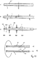
- the workpieces 1 made of wood, plastic and the like are planed in a continuous process.
- the right and left longitudinal sides 3, 4 of the workpiece 1 are planed in the direction of passage 2 by the machine so that at least one longitudinal side is at an acute angle to the direction of passage 2.
- Fig. 3 shows, but the workpieces 1 can also be planed so that both longitudinal sides 3, 4 with the passage direction 2 each include an acute angle.
- the workpieces 1 are board-like fins, from which, for example, house walls are produced.
- the conical workpieces 1 with their longitudinal sides 3, 4 are fixedly connected to each other, for example by means of a corresponding adhesive layer.
- the conical workpieces 1 are here each rotated rotated by 180 °.
- the adjoining, glued together workpieces 1 are pressed transversely to their longitudinal sides 3, 4.
- the machine for producing the conical workpieces 1 is a continuous machine with a dressing table 5, on which the workpieces 1 are fed to the machine.
- the dressing table 5 is located on the inlet side of the machine.
- feed / transport rollers 6 are provided which are rotatably driven and rest on the workpieces 1.
- the dressing table 5 may be adjustable in the vertical direction to adjust the amount of chip removal on the underside of the workpiece 1.
- the workpiece 1 is located on the right side of the dressing table 5 in the feed direction on a in the direction 2 extending stop ruler 7 with its right in the direction of passage 2 longitudinal side 3 at.
- the right longitudinal side 3 of the workpiece 1 is provided with a curvature extending over its length, so that the workpiece 1 rests against the stop ruler 7 only in the region of its front and its rear end with the longitudinal side 3.
- a horizontal lower dressing spindle on which a schematically illustrated dressing tool 9 rotatably seated.
- the underside of the workpiece 1 is machined, preferably straight planed.
- the workpiece removal is determined by the height of the dressing table 5 relative to the dressing tool 9.
- the tool 10 is a planing head with straight blades, with which the longitudinal side 3 of the workpiece 1 is straight planed during the pass.
- the spindle 10 carrying the tool is adjustable transversely to the direction of passage 2.
- Fig. 1 is the adjustment direction denoted by 11, which is perpendicular to the direction of passage 2 and horizontal.
- the machine is provided with a vertical left spindle, on which a tool 12 rotatably seated.
- the spindle of this tool 12 is also transverse, preferably perpendicular to the passage 2 in the horizontal direction adjustable.
- the corresponding adjustment direction is indicated by 13.
- the workpiece 1 lies with its one broad side on the machine table 8, which forms a horizontal support and reference plane for the workpieces 1.
- the workpieces 1 are guided in the direction of passage 2 to the right tool 10 with a small distance to a stop 14 through the machine. It is parallel to the direction of passage 2 and is machine-fixed.
- the transport of the workpieces 1 on the machine table 8 is also carried out with the feed / transport rollers 6, which are arranged in the direction of passage 2 at a distance one behind the other and are rotatably driven.
- the feed / transport rollers 6 rest on the workpiece 1.
- the machine In the direction of passage 2 behind the left vertical spindle, the machine is provided with an upper horizontal spindle, rotatably on a tool 15 sits. With him the top of the workpiece 1 is machined as it passes through the machine.
- Fig. 1 further shows, the machine is provided at a distance behind the tool 15 with a lower horizontal spindle, rotatably on a tool 16 sits. With him, the bottom of the workpiece 1 can be processed during the pass.
- the machine In the direction of passage 2 at a distance behind the tool 16, the machine has a horizontal lower table roller 17 for better transport of the workpieces first
- the workpiece 1 to be machined is fed to the dressing table 5 of the machine.
- the dressing table 5 In the area of the dressing table 5 are two sensors 18 and 19, between which the workpiece 1 in the direction of the machine or the machine table 8 is transported.
- Fig. 4 shows, the right longitudinal side 3 of the workpiece 1 is curved over its length. In Fig. 4 this curvature is exaggerated for clarity. Due to the curved longitudinal side 3, the workpiece 1 rests against the stop ruler 7 only with its front and its rear end.
- the curvature occurs due to storage and drying, with ungedäumten workpieces 1 due to the natural growth of the tree trunks and due to released tensions in trimmed or teilbeklamten workpieces.
- the still unprocessed workpieces 1 are fed to the dressing table 5 in the correct position by an upstream mechanization.
- the workpieces 1 are scanned and advantageously supplied so that the workpieces rest against the stop ruler 7 of the dressing table 5 with the curved hollow longitudinal side 3.
- the two longitudinal sides 3, 4 of the workpiece 1 are advantageously scanned without contact.
- the sensors 18, 19 may be, for example, laser distance sensors with which the longitudinal sides 3, 4 can be scanned.
- the sensors 18, 19 are connected to a controller (not shown) to which the sensor signals are supplied. With these sensor signals, the control then ensures that the tools 10, 12 following in the direction of passage 2 are set radially so that the necessary workpiece removal takes place on the longitudinal sides 3, 4.
- the two sensors 18, 19 are arranged stationary. With them, the degree of curvature or taper of the tool 1 can be detected in a simple manner.
- the sensor 18 determines the chip removal on the right longitudinal side 3 of the workpiece 1. Accordingly, the right tool 10 is adjusted radially in the adjustment 11 so that the initially curved longitudinal side 3 is planed by the tool 10 via the controller. The tool 10 does not move during the planing process, but maintains its set by the controller position during the passage of the workpiece 1 at.
- the sensor 18 has in the direction of passage 2 a distance from the tool 10th which is greater than the maximum length of the workpiece to be machined 1. Then, the tool 10, before it comes into engagement with the supplied from the dressing table 5 workpiece 1, in its necessary radial position be adjusted in the adjustment 1, since the sensor 18 has previously detected the workpiece 1 over its length and has supplied the corresponding sensor signals to the controller.
- the sensor 19 lies opposite the longitudinal side 4 of the workpiece 1 at a distance and detects the course of this longitudinal side during the workpiece pass. With the aid of the sensor 19, the conicity of the workpiece 1 and the degree of chip removal on the longitudinal side 3 can be determined by the tool 12.
- the relative position of the longitudinal side 4 of the workpiece 1 with respect to the passage direction 2 can be easily detected.
- the sensor beam 20 emitted by the sensor 19 is reflected back to the sensor 19 on the longitudinal side 4 of the workpiece 1 and the distance of the workpiece from the sensor is determined therefrom. This virtually achieves a continuous width measurement of the workpiece in the pass.
- the two tools 10, 12 are advantageously CNC-controlled in their respective positions in the adjustment direction 11, 13 adjusted. Due to the oblique position of the longitudinal side 4, the tool 12 in contrast to the tool 10th adjusted accordingly during the passage of the workpiece 1 in the adjustment 13. According to the embodiment Fig. 1 the tool 12 is initially adjusted so far in the direction of the stop 14 that it can remove 1 material in the region of the longitudinal side 4 at the narrower end of the workpiece. Corresponding to the course of the longitudinal side 4, the tool 12 is moved back in the adjustment 13 CNC-controlled, so that the tool 12 has the largest distance from the stop 14 when the workpiece 1 has been transported past the tool 12. Subsequently, the tool 12 is driven back into a starting position via the controller, which is based on the width of the subsequent workpiece 1 at the front in the direction of passage 2 end.
- the machine 12 fixedly arranged during the passage of the workpiece 1 tool 12 is, before it comes into engagement with the workpiece 1, adjusted by means of the signals of the sensor 18 by the controller in the adjustment 11 so that on the long side 3 with minimal chip removal as much material from Workpiece 1 is removed, that it has a parallel to the direction of passage 2 extending and extending over its length completely clean planed straight longitudinal side 3, when it has been processed by the tool 10.
- Fig. 2 This is in Fig. 2 shown.
- the longitudinal side 3 of the workpiece 1 is machined by the tool 10 such that the longitudinal side 3 extends over the length of the workpiece 1 parallel to the passage direction 2.
- the opposite longitudinal side 4 of the workpiece 1 is processed by the tool 12 so that the longitudinal side 4 extends straight over the length of the workpiece 1. Due to the oblique position of the longitudinal side 4, the tool 12, as is apparent from Fig. 2 results in correspondingly continuously shifted in the adjustment 13 radially CNC-controlled.
- the workpiece 1 is, before it reaches the machine table 8, on its underside 21 (FIG. Fig. 1 and 4 ) with a running in the direction of passage 2 Groove 22 provided.
- the groove 22 is milled with the dressing tool 9 in the bottom 21.
- the machine table 8 which is arranged on a machine stand 23 ( Fig. 5 ), is provided with a projecting, in the direction of passage 2 extending guide web 24 which engages in the groove 22 of the workpiece 1.
- the width of the guide web 24 is matched to the width of the groove 22 so that the workpiece 1 is guided cleanly in the direction of passage 2.
- the top and the bottom of the workpiece 1 are smooth planed during the passage.
- the bottom 21 of the workpiece 1 can be shaved off so that the groove 22 is removed. It is only so deep that with the help of the guide bar 24 of the machine table 8, the workpiece 1 can be reliably performed. Therefore, only a small amount of material on the workpiece underside 21 has to be removed with the tool 16 in order to remove the groove 22. The loss of material is therefore very low.
- Fig. 5 shows, there is a small distance 25 between the right in the direction 2 longitudinal side 3 of the workpiece 1 and the stopper 14, so that it is ensured that the workpiece 1 is guided during passage through the machine only through the guide web 24 in the direction of passage 2.
- the workpieces 1 have a greater width transversely to the direction of passage 2, it may be advantageous, for example, to mill two spaced-apart grooves 22 in the underside 21 of the workpiece 1 in order to ensure reliable guidance of the workpieces 1, even with greater width.
- the dressing tool 9 is accordingly designed so that the grooves can be milled with it.
- both tools 10, 12 are adjusted during the passage of the workpiece 1 through the machine in the manner described radially in the direction of 11 or 13, corresponding to the slope of the longitudinal sides 3, 4.
- the adjustment of the tools 10, 12 during the workpiece pass again takes place via the controller, which evaluates the signals of the sensors 18, 19 and generates the adjustment of the tools 10, 12 during workpiece pass.
- the workpieces 1 are transported continuously through the machine.
- the distance between successive workpieces 1 can be kept low because the CNC control can adjust the tools 10, 12 in a short time positionally accurate.
- the machine has a high throughput per unit time.
- the workpieces 1 After the workpieces 1 have been conically planed in the manner described, they are assembled in a subsequent process to form larger elements.
- the workpieces 1 can each be alternately rotated by 180 ° with their longitudinal sides 3, 4 abutting and connected to each other by an adhesive bond.
- the adjacent workpieces In a press, the adjacent workpieces are pressed against each other so that there are stable plates. They can be used, for example, as individual plates for a wide variety of applications.
- the longitudinal sides 3, 4 can be produced with high surface quality and high straightness, so that the conical workpieces 1 can then be reliably glued to plates in the manner previously described.
- the contour of the longitudinal side 4 is determined and determined from the travel of the tool 12.
- the feed travel is determined by the feed rate at which the workpiece 1 is transported through the machine, and by the detection of the workpiece start in the machine
- a sensor 26 is provided ( Fig. 1 and 4 ), which is located in the area above the workpiece 1 and through the detection area, the workpiece is transported through.
- To determine the transport / feed path and measuring wheels can be used, which bear against the corresponding workpiece longitudinal side, advantageously the workpiece top.
- a sensor can be used, with which the beginning of the workpiece is detected.
- these can be adjusted by adjusting the adjustment speed of the tools 10 or 12 as a function of Feed path or the feed rate of the workpiece 1 are processed so that the respective longitudinal sides 3, 4 are inclined differently with respect to the passage direction 2.
- defined conicity classes can be achieved.
- the workpieces 1 are each transported with their narrower end, the so-called pigtail, forward through the machine.
- the workpieces 1 can also be arranged so that they are transported with their wider end forward through the machine.
- conical boards can be produced in a glueable quality and at a high raw wood yield.
- the high raw wood yield ie the maximum deck width, results from the measurement of the narrow sides of the workpieces and the processing derived from them with minimal chip removal, and also from the use of conical starting boards, which were produced in an upstream process according to the natural growth habit of the trees ,
- Fig. 6 shows a workpiece 1, the straight, parallel edged edges 3, 4, which extend over only a portion of the workpiece length.
- the edges 3, 4 extend over more than half the length of the workpiece 1, advantageously over about two thirds of the length of the Workpiece 1.
- This advantageous length of the just edged edges 3, 4 is advantageous in view of the stackability of the workpieces after sawing.
- the edges 3, 4 are sufficiently long in this case, so that the workpieces 1 with these edges 3, 4 can be transported adjacent to each other transversely to the longitudinal direction of the workpieces 1.
- the so-called forest edges 27, 28 have not yet been processed by the Beklamrea and the workpiece runs to its narrower end to. Even in the trimmed area, part of the edge of the forest may still be present, viewed over the workpiece thickness.
- the workpiece 1 is shown after processing.
- the workpiece 1 after processing over its length continuously straight longitudinal sides 3, 4, which converge in the direction of the narrower end of the workpiece 1.
- the workpiece 1 can in this case be processed so that it is mirror-symmetrical with respect to a symmetry line 29. Then, by way of example, there is the possibility of sawing the workpiece 1 into two workpieces along its line of symmetry 29 after being machined ( Fig. 10 ).
- Fig. 6 three workpiece cross-sections are shown. In the region of the straight edges 3, 4 at the workpiece beginning, in which the workpiece 1 is trimmed over its entire thickness (thickness), the workpiece 1 has a rectangular cross-section I.
- the unprocessed workpiece 1 has the cross-sectional shapes II and III, respectively.
- the forest edges 27, 28 extend from the bottom 30 of the workpiece 1 in the direction of the top 31 converging.
- the workpiece 1 When the workpiece 1 is finished, it has a rectangular cross-section throughout its length, with the width of the workpiece 1 decreasing continuously towards the narrower end.
- the unprocessed workpiece is detected from the top during its transport in the direction of the tools of the machine, preferably by means of scanners. They are arranged so that they cover the lower edge 32 and the upper edge 33 of the forest edges 27, 28.
- the tools 10, 12 can then be adjusted so that the desired contour of the workpiece 1 can be produced with minimal chip removal.
- the workpiece 1 may additionally be provided with respect to its length as well as the beginning and the end of the workpiece 1 by the sensors 18, 19, 26 (FIG. Fig. 4 ).
- the desired conicity (dashed lines) of the workpiece 1 can be adjusted so that the finished workpiece can be assigned to a specific conicity class.
- detection means which grasp the workpiece 1 from above, imaging systems such as cameras or also a cross-pass scanner, a longitudinal scroll scanner and the like can also be used.
- the workpieces 1 are arranged in the feed on the dressing table 5 and the machine table 8 so that the forest edges 27, 28 extend from the support side 30 upwards and obliquely inwards. Then, the detection means, which are arranged in the area above the workpiece 1, the two edges 32, 33 of the forest edges 27, 28 detect.
- the detection device is advantageously arranged in the feed region of the workpieces 1 to the machine.
- the respective workpiece identification in the machine can be ensured via the exact part tracking or by means of a marking, for example by means of a barcode, transponder and the like.
- the workpieces 1 may deviate from the training according to Fig. 6 be untrimmed. Depending on the growth habit and the course of the forest edge 27, 28, the unprocessed workpiece 1 can also be trimmed conically or, as in the illustrated embodiment, be trimmed in parallel over a partial length.
- Fig. 7 shows a machine which is basically the same design as the embodiment according to Fig. 3 , The difference is that the feed / transport rollers 6, seen in plan view, are approximately half the width of the workpiece 1.
- the feed / transport rollers 6 are advantageously adjustable transversely to the direction of passage 2 of the workpiece 1, so that the feed / transport rollers 6 can be optimally adjusted depending on the width of the workpiece 1.
- Fig. 8 shows the inlet area of the continuous machine according to Fig. 7 with the dressing table 5, on which the workpieces 1 are supplied.
- the feed / transport rollers 6 are provided at a distance one behind the other about half the width of the workpiece 1 are arranged.
- the feed / transport rollers 6 are adjustable to the width of the workpiece 1, so that they can be reliably transported through the machine.
- Fig. 8 shows the inlet of the workpiece 1 in the moulder, which is processed in the same manner as according to the embodiment according to Fig. 3 explains:
- the workpiece 1 according to Fig. 8 is conically formed on both sides and can be an unedged conical or a conically edged workpiece. But it can also be fully trimmed in parallel or at least over a partial length.
- the workpiece 1 is fed from a stack (not shown) transverse to its longitudinal direction.
- the workpiece 1 can be partially trimmed, trimmed or not trimmed and optionally have the forest edges 27, 28.
- the workpiece 1 is scanned from above by means of a cross-pass scanner 26 "(dotted lines in step 1 of FIG Fig. 9 ), whereby in the described manner, in particular in the region of the forest edges 27, 28 their lower edge 32 and their upper edge 33 can be detected.
- the beginning and the end of the workpiece 1 can be detected and the corresponding measured values can be fed to the controller.
- the advantageous later orientation for feeding into the processing area of the machine is also determined.
- the controller ensures that the tools are adjusted so that the required workpiece removal is performed on the longitudinal sides of the workpiece 1.
- the scanning process can be realized by a cross pass scanner 26 "or longitudinal scan scanner.
- edged workpieces to the Fügelineal 7, as based Fig. 1 described, created and then fed to the processing.
- edge of the forest is not completely edged, it is expedient that the right-hand tools 10, 10 'are nevertheless transversely adjusted during the continuous processing and that the workpiece 1 is processed conically.
- the orientation of the workpiece with respect to the direction of passage 2 is checked. If necessary, a correction of the intended machining is made via the CNC control, by taking this into account when adjusting the corresponding tool transversely to the direction of passage 2.
- the work to be performed on the workpiece 1 is in step 2 of Fig. 9 exemplified by lines 35, 36.
- lines 35, 36 it is indicated that the workpiece 1 is designed to be tapered conically over its entire length after being machined.
- the processing lines 35, 36 converge in the direction of passage 2.
- the groove 22 with the dressing tool 9 (FIG. Fig. 1 and 4 ) (step 3.1 in Fig. 9 ).
- the workpiece 1 is pre-planed / pre-planed on the right and left (3.2 in step 3 of FIG Fig. 9 ).
- the right 10, 10 'and left tools 12, 12' viewed in the direction of passage 2, are arranged directly opposite each other.
- the workpiece 1 is finished planed at its longitudinal sides running in the direction of passage 2 with the corresponding tools 10 ', 12' (3.3 at step 3 of FIG Fig. 9 ).
- the tools 10, 12; 10 ', 12' are continuously adjusted during the feed of the workpiece 1 transversely to the direction of passage 2 according to the desired Konizticianswinkel, as has been explained in detail in the first embodiment.
- Fig. 9a is this a workpiece 1 with "1.” and the second workpiece with “2.” designated.
- the two workpieces have the same conicity and are advantageously removed from an intermediate buffer (not shown).
- the workpiece "2.” is rotated about an axis transverse to its longitudinal axis so that the narrower end adjacent to the wider end of the workpiece "1.” and the wider end of the workpiece “2.” next to the narrower end of the workpiece "1.” lies.
- Fig. 9b In another procedure ( Fig. 9b ), the workpieces are first separated into two equally long workpiece parts 1.1 and 1.2. Then one of the two workpiece parts is rotated so that it lies with its narrower end next to the wider end of the other workpiece part.
- the board pair 37 thus formed in turn has parallel longitudinal sides, but is only half as long as the board pair 37 according to Fig. 9a ,
- Steps 1 and 2 in Fig. 10 essentially correspond to the steps 1 and 2 according to Fig. 9 , In step 2, however, the workpiece is aligned so that its axis of symmetry 29 extends in the direction of passage 2 and relative to a (not shown) dicing saw so that the workpiece 1 can be preferably divided over its length in half the width.
- step 3 the operations 3.1 to 3.3 are performed in the same way on the workpiece 1 as in the embodiment according to Fig. 9 , wherein the conical machining of the two longitudinal sides is also symmetrical, ie with the same angle.
- the longitudinal sawing of the workpiece takes place 1 during its transport in the direction of passage 2.
- the corresponding (not shown) cutting saw is advantageously in the area below the workpiece 1, but can also be arranged in the region above the workpiece 1 so that it separates the workpiece 1 in the longitudinal direction.
- the separating cut 38 produced by the cutting saw lies in an axis parallel to the axis of symmetry 29 of the workpiece 1.
- the separating cut 38 lies in the axis of symmetry 29, as a result of which the workpiece is separated by half the width.
- the workpiece 1 is planed on the top and bottom and thus brought to the desired board thickness.
- Fig. 10a shows the two workpiece parts 1.1, 1.2, which have been generated after the separation of the workpiece 1 in step 3. Both workpiece parts 1.1, 1.2 have due to the separating cut 38 parallel longitudinal sides 40, 41. To these long sides 40, 41 extend the outer longitudinal sides 3, 4 at an angle. As a result, the workpiece parts 1.1, 1.2 have a wider and a narrower end.
- the resulting workpiece parts 1.1, 1.2 can be further processed directly. There is no buffer required for the workpiece parts.
- workpieces 1 not only taking into account the Konizitästail, but also taking into account branch positions in the workpieces (workpiece beginning, workpiece center, workpiece end) in different buffers store.
- the workpieces 1 can then be removed from the buffers and collapsed into the board carpet so that little waste is produced in the later process step of cutting (removing) branches.
- the conical machining is performed by the corresponding tool is adjusted transversely to the direction of passage 2.
- the conical workpieces 1 thus produced are temporarily stored in buffers according to the conicity class. From this buffer then the workpieces in the process after Fig. 9a fed to form an endless board carpet, in each case from two workpieces, the pairs of boards 37 are formed, which are placed against each other to form the board carpet.
- the pairs of boards 37 are each made of workpieces 1 from the same class Konizticianst. One of these workpieces is rotated in the manner described in its plane about a transverse axis by 180 °. As a result, the two conical workpieces 1, 2 ( Fig. 9a ) the board pair 37 with parallel longitudinal sides or with approximately rectangular outline.
- the workpieces 1 are scanned to determine the conical processing position.
- the consideration of Konizticianst is not necessary in this procedure, since the workpiece parts 1.1, 1.2 are not stored in buffers, but continue to be processed immediately.
- the scanned workpiece 1 is fed to the molding machine and aligned according to the machining position.
- the orientation of the workpiece 1 during transport in the molding machine is checked. If necessary, a correction of the processing by a corresponding adjustment of the tool.
- the groove 22 On the underside of the workpiece 21, the groove 22 is mounted, in which the guide web 24 engages. By adjusting the tool transversely to the direction of passage 2, the conical machining of the workpiece 1.
- the workpiece 1 is divided by transverse separation in the two workpiece parts 1.1 and 1.2.
- One of these workpiece parts is then rotated by 180 ° in its plane.
- the workpiece parts 1.1, 1.2 are then brought together in the manner described for board pair 37. From the board pairs 37 thus formed, the endless carpet is produced, this carpet having a width which corresponds to half the length of the starting workpieces 1.
- the workpieces 1 are first scanned and this determines the conical machining position. In addition, the running in the direction of feed 2 center axis of the workpiece 1 is determined. Subsequently, the workpiece 1 is fed to the molding machine and aligned in accordance with the determined central axis 29. During the transport of the workpiece 1 in the molding machine, the workpiece alignment can optionally be checked. If necessary, a correction of the machining is made by the tool is adjusted accordingly. On the underside of the workpiece 21, the groove 22 is introduced for the guide web 24. Then the workpiece is machined by appropriate adjustment of the tool during its passage through the molding machine.
- the separation process takes place in the described manner, in which the workpiece 1 is separated in its longitudinal direction into the two workpiece parts 1.1 and 1.2. Since these workpiece parts 1.1, 1.2 are further processed immediately afterwards, a buffer is not necessary. This also eliminates the need for processing by Konizticianstn, because two workpiece parts to form the pairs of boards 37 are placed together, have the parallel outer longitudinal sides. These pairs of boards are joined together to form the endless board carpet.
- the side edges with the vertical tools 10, 10 ', 12, 12' processed so that the sides of the workpieces are perpendicular to the top and bottom of the workpieces. It is also possible to edit the longitudinal sides 3, 4 of the workpieces 1 with inclined tools or with profile tools. As a result, the longitudinal sides 3, 4 are formed obliquely to the top and bottom.
- the workpieces therefore have a trapezoidal cross-section. This can significantly increase the yield of wood.
- the one workpiece part 1.2 ( Fig. 10b ) in addition to the 180 ° rotation in the plane from the bottom to the top, before the workpieces or workpiece parts are connected to each other to form the board carpet.
- This rotation causes, as in Fig. 10b , represented the two workpiece parts 1.1, 1.2 with their oblique longitudinal sides 3, 4 abut each other.
- the longitudinal side 40 of the workpiece part 1.2 becomes an outer side of the board pair 37
- the longitudinal side 41 of the other workpiece part 1.1 forms the other outside of the board pair 37th
Landscapes
- Life Sciences & Earth Sciences (AREA)
- Engineering & Computer Science (AREA)
- Mechanical Engineering (AREA)
- Wood Science & Technology (AREA)
- Forests & Forestry (AREA)
- Milling, Drilling, And Turning Of Wood (AREA)
- Finish Polishing, Edge Sharpening, And Grinding By Specific Grinding Devices (AREA)
Applications Claiming Priority (2)
| Application Number | Priority Date | Filing Date | Title |
|---|---|---|---|
| DE102018002704 | 2018-03-29 | ||
| DE102019001921.0A DE102019001921A1 (de) | 2018-03-29 | 2019-03-16 | Maschine und Verfahren zum konischen Bearbeiten, insbesondere zum konischen Hobeln, von Werkstücken aus Holz, Kunststoff und dergleichen |
Publications (1)
| Publication Number | Publication Date |
|---|---|
| EP3546163A1 true EP3546163A1 (fr) | 2019-10-02 |
Family
ID=67910227
Family Applications (1)
| Application Number | Title | Priority Date | Filing Date |
|---|---|---|---|
| EP19000148.7A Pending EP3546163A1 (fr) | 2018-03-29 | 2019-03-26 | Machine et procédé d'usinage conique, en particulier de rabotage conique, des pièces en bois, en matière plastique et analogue |
Country Status (3)
| Country | Link |
|---|---|
| US (1) | US11345058B2 (fr) |
| EP (1) | EP3546163A1 (fr) |
| DE (1) | DE102019001921A1 (fr) |
Cited By (2)
| Publication number | Priority date | Publication date | Assignee | Title |
|---|---|---|---|---|
| CN111452144A (zh) * | 2020-06-04 | 2020-07-28 | 戚利明 | 一种木材加工装置 |
| WO2023213873A1 (fr) * | 2022-05-05 | 2023-11-09 | Homag Gmbh | Dispositif et procédé d'usinage |
Families Citing this family (2)
| Publication number | Priority date | Publication date | Assignee | Title |
|---|---|---|---|---|
| BE1027083B1 (nl) * | 2019-02-26 | 2020-09-24 | Flooring Ind Ltd Sarl | Glij- of drukschoen voor een doorloopfreesmachine en werkwijze voor het vervaardigen van panelen |
| CN114633319A (zh) * | 2022-03-14 | 2022-06-17 | 广西华辉装饰集团有限公司 | 一种多功能开槽一体机 |
Citations (3)
| Publication number | Priority date | Publication date | Assignee | Title |
|---|---|---|---|---|
| DE102004054973A1 (de) * | 2004-11-13 | 2006-07-13 | Homag Holzbearbeitungssysteme Ag | Doppelendprofiler mit Werkstück-Führungsschiene und Verfahren zur Herstellung von Werkstücken hiermit |
| BE1016561A6 (nl) * | 2005-03-31 | 2007-01-09 | Flooring Ind Ltd | Werkwijzen voor het vervaardigen en verpakken van vloerpanelen, alsmede vloerpaneel en verpakte set van vloerpanelen. |
| WO2015086332A1 (fr) * | 2013-12-10 | 2015-06-18 | Hans-Peter Leitinger | Panneau de bois de sciage constitué de planches latérales et procédé de production de ceux-ci |
Family Cites Families (13)
| Publication number | Priority date | Publication date | Assignee | Title |
|---|---|---|---|---|
| US769980A (en) | 1904-01-12 | 1904-09-13 | Charles W Borg | Tongue-shaping machine. |
| FR1394002A (fr) | 1963-08-02 | 1965-04-02 | Constant Philips | Dispositif de rabotage pour dégauchir le bois pour machines à raboter le bois sur plusieurs faces |
| SE314495B (fr) | 1967-10-10 | 1969-09-08 | Stenbergs Maskinbyra Ab | |
| US3934630A (en) * | 1973-04-16 | 1976-01-27 | Cockle Roy R | Method and apparatus for producing rough cut lumber |
| US4230163A (en) * | 1978-02-27 | 1980-10-28 | Vermont Log Building, Inc. | Log-planing machine |
| US5447186A (en) * | 1993-12-20 | 1995-09-05 | Sawquip International, Inc. | Chipping canter |
| DE19616165A1 (de) | 1996-04-24 | 1997-10-30 | Hoffmann & Kuehnhenrich Gmbh | Spanabhebende Bearbeitungsmaschine |
| DE19756503B4 (de) | 1997-12-19 | 2007-09-27 | Michael Weinig Ag | Kehlmaschine |
| US6062281A (en) * | 1999-05-13 | 2000-05-16 | U.S. Natural Resources | Vertical arbor saw for shape sawing a log |
| DE10328204A1 (de) | 2003-06-24 | 2005-02-03 | Homag Holzbearbeitungssysteme Ag | Maschine zum Profilieren von länglichen, plattenförmigen Werkstücken entlang der Längskanten |
| US20110079324A1 (en) * | 2007-03-20 | 2011-04-07 | McDonough Manufacturing | Board edger with tandem saw boxes |
| CA2770635C (fr) * | 2011-03-07 | 2019-02-19 | Earl Barker | Systeme de verification de scierie base sur la visionique |
| US10029384B2 (en) | 2014-01-15 | 2018-07-24 | Baxley Equipment Co. | Lumber edger and method of edging lumber |
-
2019
- 2019-03-16 DE DE102019001921.0A patent/DE102019001921A1/de active Pending
- 2019-03-26 EP EP19000148.7A patent/EP3546163A1/fr active Pending
- 2019-03-29 US US16/368,904 patent/US11345058B2/en active Active
Patent Citations (3)
| Publication number | Priority date | Publication date | Assignee | Title |
|---|---|---|---|---|
| DE102004054973A1 (de) * | 2004-11-13 | 2006-07-13 | Homag Holzbearbeitungssysteme Ag | Doppelendprofiler mit Werkstück-Führungsschiene und Verfahren zur Herstellung von Werkstücken hiermit |
| BE1016561A6 (nl) * | 2005-03-31 | 2007-01-09 | Flooring Ind Ltd | Werkwijzen voor het vervaardigen en verpakken van vloerpanelen, alsmede vloerpaneel en verpakte set van vloerpanelen. |
| WO2015086332A1 (fr) * | 2013-12-10 | 2015-06-18 | Hans-Peter Leitinger | Panneau de bois de sciage constitué de planches latérales et procédé de production de ceux-ci |
Cited By (2)
| Publication number | Priority date | Publication date | Assignee | Title |
|---|---|---|---|---|
| CN111452144A (zh) * | 2020-06-04 | 2020-07-28 | 戚利明 | 一种木材加工装置 |
| WO2023213873A1 (fr) * | 2022-05-05 | 2023-11-09 | Homag Gmbh | Dispositif et procédé d'usinage |
Also Published As
| Publication number | Publication date |
|---|---|
| DE102019001921A1 (de) | 2019-10-02 |
| US20190299483A1 (en) | 2019-10-03 |
| US11345058B2 (en) | 2022-05-31 |
Similar Documents
| Publication | Publication Date | Title |
|---|---|---|
| EP3546163A1 (fr) | Machine et procédé d'usinage conique, en particulier de rabotage conique, des pièces en bois, en matière plastique et analogue | |
| EP3294510B1 (fr) | Procédé de fabrication de panneaux comportant des évidements | |
| DE3343953A1 (de) | Verfahren zur bearbeitung gekruemmter staemme | |
| EP2308659B1 (fr) | Dispositif et procédé destinés à aligner des pièces à usiner | |
| EP3453503B1 (fr) | Machine d'usinage de pièces à usiner oblongues en bois, en plastique et analogues ainsi que procédé de mesure de telles pièces à usiner oblongues | |
| DE102011002209A1 (de) | Vorrichtung zur schleifenden Materialtrennung | |
| DD289967B5 (de) | Verfahren und Vorrichtung zur Herstellung von Holzlamellen aus Schnittholz | |
| EP3498423B1 (fr) | Dispositif d'usinage destiné à usiner un petit côté de pièce à usiner ainsi que procédé | |
| DE19756280A1 (de) | Kehlmaschine | |
| EP2221134B1 (fr) | Dispositif de traitement | |
| DE2947993C3 (de) | Verfahren zum Längsschneiden von Holzstücken | |
| DE4212432A1 (de) | Vorrichtung zum spanlosen Abschneiden von Holzlamellen von einem Kantholz | |
| DE2920755A1 (de) | Einrichtung und verfahren zum stirnseitigen zusammensetzen von hoelzern mittels keilzinkenverbindungen | |
| EP3365147A1 (fr) | Procédé permettant d'enturer des feuilles de contreplaqué | |
| EP2665587B1 (fr) | Machine à moulurer pour l'usinage de pièces en forme de barres en bois, matière plastique ou similaire | |
| DE102017011825B4 (de) | Verfahren zum Auftrennen länglicher Werkstücke aus Holz, Kunststoff und dergleichen in Lamellen sowie Bearbeitungsmaschine zur Durchführung eines solchen Verfahrens | |
| EP3659765A1 (fr) | Dispositif d'usinage de pièces en bois allongées, en matière plastique et analogues | |
| DE3514892C1 (de) | Verfahren und Vorrichtung zum Zerspanen von Holz, insbesondere zur spanenden Zerlegung von mit Baukanten versehenen Baumstämmen | |
| DE19547193A1 (de) | Verfahren und Vorrichtung zum Einschneiden eines Baumstammes | |
| EP1365899A2 (fr) | Procede et dispositif pour decouper des bois ronds courbes dans un plan afin d'obtenir des produits ligneux | |
| DE3607146A1 (de) | Verfahren und maschine zur bearbeitung von kanteln | |
| DE102004051933A1 (de) | Vorrichtung und Verfahren zum Profilieren von Baumstämmen | |
| DE4138734C2 (de) | Verfahren und Vorrichtung zur Bearbeitung beider Längsseiten von in Längsrichtung geförderten Schnitthölzern | |
| DE19509653C1 (de) | Verfahren zur Herstellung von dünnen Brettern, insbesondere Parkettlamellen | |
| DE102019002689A1 (de) | Verfahren zur Herstellung einer Längsnut mit Hinterschneidung in einem Werkstück aus Holz, Kunststoff und dergleichen sowie Maschine zur Durchführung eines solchen Verfahrens |
Legal Events
| Date | Code | Title | Description |
|---|---|---|---|
| PUAI | Public reference made under article 153(3) epc to a published international application that has entered the european phase |
Free format text: ORIGINAL CODE: 0009012 |
|
| STAA | Information on the status of an ep patent application or granted ep patent |
Free format text: STATUS: THE APPLICATION HAS BEEN PUBLISHED |
|
| AK | Designated contracting states |
Kind code of ref document: A1 Designated state(s): AL AT BE BG CH CY CZ DE DK EE ES FI FR GB GR HR HU IE IS IT LI LT LU LV MC MK MT NL NO PL PT RO RS SE SI SK SM TR |
|
| AX | Request for extension of the european patent |
Extension state: BA ME |
|
| STAA | Information on the status of an ep patent application or granted ep patent |
Free format text: STATUS: REQUEST FOR EXAMINATION WAS MADE |
|
| 17P | Request for examination filed |
Effective date: 20200402 |
|
| RBV | Designated contracting states (corrected) |
Designated state(s): AL AT BE BG CH CY CZ DE DK EE ES FI FR GB GR HR HU IE IS IT LI LT LU LV MC MK MT NL NO PL PT RO RS SE SI SK SM TR |
|
| STAA | Information on the status of an ep patent application or granted ep patent |
Free format text: STATUS: EXAMINATION IS IN PROGRESS |
|
| 17Q | First examination report despatched |
Effective date: 20210804 |